

Page 1
OWNER’S MANUAL
Model #:
EUROTEKPRO-11DD
comes standard with
the 11” Biaxial DD
searchcoil
Use a 9-volt ALKALINE battery only.
Do not use “Heavy Duty” batteries.
Do not use ordinary Zinc Carbon batteries.
Page 2

ACCESSORIES
Teknetics® Padded Carrying Bag
.
Made of rugged double-stitched nylon construction.
Includes handy outside zip-pocket for extra batteries or
small accessories. – CBAG-T
Teknetics® Camo Pouch
Camo pouch with two inside pockets, belt included. -
PCH-T
Teknetics® Stereo Headphones
Use with Teknetics® metal detectors with true stereo. Utilizes 1/4-inch stereo
& 1/8-inch plug. Compatible with all Teknetics
®
models with 1/4-inch &
1/8-inch jacks. –HEADT
Arm Strap
Secure your detector to your arm for a perfect swing
– 2021112000
Teknetics® Pinpointer
Pinpoints the exact location of buried metal objects. Audio signal indicator
and vibrator. No assembly required, runs on (1) 9-Volt
Battery
.
–PINPOINTER
Digging Trowel
One-piece stainless steel construction with depth gauge
- TROWEL-2
Gold Pick
Tem pered steel head is 10” long and the edge is 3 1/4” wide. The overall
length is 19” with a durable fiberglass handle and a
rubberized hand grip.
Includes a powerful magnet attached to the head
to quickly discriminate iron targets and magnetic hot rocks. –
GOLDPICK
Lesche Knife
Made from high quality heat-treated tempered steel. The ultimate
digging tool. Comes with a durable sheath.
12" in length with a 7" serrated blade -
LESCHE KNIFE
Eurotek® T-Shirt
100% cotton with Erotek® Logo. Sizes LG, XL & XXL
-
ETPSHIRT
Eurotek® Baseball Cap
One size fits all -
ETPCAP
Rain Cover
Custom made to protect from weather
-RAINCOV-ET
Extended Lower Stem
For taller users
-TUBE5X
(image not shown)
Replacement & Accessory Searchcoils
and Protective Covers
Searchcoil Protective Cover
Item# Description Item#
5COIL-TEK Searchcoil, 5"DD Round, closed 5COVER-CZ3
8COIL-7TEK * Searchcoil, 8" Concentric, open 8COVER-7
10COIL-TEK Searchcoil, 10" Concentric, open F70COVER
10COILDD-TEK Searchcoil, 10"DD Ellipse, closed 2023190000
11COIL-TEK ** Searchcoil, 11"DD Ellipse, open COVER-11DD
* standard with detector
** standard with Eurotekpro-11DD
Congratulations!
Congratulations on your purchase of the new Eurotek®Pro Metal Detector. Eurotek is the result
of years of research and development to bring you a detector designed specifically for European
Treasure Hunting conditions. Treasure Hunting enthusiasts from around the world were
involved in the development of this revolutionary new detector. The Eurotek has Target-ID
resolution never before seen in a detector in this price range. Special iron identification and
audio feedback features are also an industry first. This manual has been written to help you get
optimal use of your detector, so we hope you will read it thoroughly before your first outing.
Happy Hunting from First Texas Products!
TABLE OF CONTENTS
Terminology . . . . . . . . . . . . . . . . . . . . . . . . . . . . . . . . . . . . . . . . . . . . . . . . . .3
Assembly . . . . . . . . . . . . . . . . . . . . . . . . . . . . . . . . . . . . . . . . . . . . . . . . . .4-5
Batteries . . . . . . . . . . . . . . . . . . . . . . . . . . . . . . . . . . . . . . . . . . . . . . . . . . . . .6
Quick-Start Demo . . . . . . . . . . . . . . . . . . . . . . . . . . . . . . . . . . . . . . . . . . . . .7
Basics of Metal Detecting
Headphones . . . . . . . . . . . . . . . . . . . . . . . . . . . . . . . . . . . . . . . . . . . . . . . . . .9
Operation and Controls
Menu Selections
Discrimination System
Depth Indicator . . . . . . . . . . . . . . . . . . . . . . . . . . . . . . . . . . . . . . . . . . . . . . .18
Coin Reference Table . . . . . . . . . . . . . . . . . . . . . . . . . . . . . . . . . . . . . . . . .18
Mode Selections
Other Features . . . . . . . . . . . . . . . . . . . . . . . . . . . . . . . . . . . . . . . . . . . . . . .21
Troubleshooting . . . . . . . . . . . . . . . . . . . . . . . . . . . . . . . . . . . . . . . . . . . . . .22
Accessories . . . . . . . . . . . . . . . . . . . . . . . . . . . . . . . . . . . . . . . . . . . . . . . . . .23
Code of Ethics & Warranty . . . . . . . . . . . . . . . . . . . . . . . . . . . . . . . . . . . . .24
2
Ground Minerals . . . . . . . . . . . . . . . . . . . . . . . . . . . . . . . . . . . . . . . .8
Trash . . . . . . . . . . . . . . . . . . . . . . . . . . . . . . . . . . . . . . . . . . . . . . . . .8
Identifying Buried Objects . . . . . . . . . . . . . . . . . . . . . . . . . . . . . . . . .8
Size and Depth of Objects . . . . . . . . . . . . . . . . . . . . . . . . . . . . . . . .8
Electromagnetic Interference . . . . . . . . . . . . . . . . . . . . . . . . . . . . . .9
Power On and Work the Controls . . . . . . . . . . . . . . . . . . . . . . . . . .10
Overview . . . . . . . . . . . . . . . . . . . . . . . . . . . . . . . . . . . . . . . . . . . . .11
Sensitivity . . . . . . . . . . . . . . . . . . . . . . . . . . . . . . . . . . . . . . . . . . . .11
Discrimination . . . . . . . . . . . . . . . . . . . . . . . . . . . . . . . . . . . . . . . . .12
Volume . . . . . . . . . . . . . . . . . . . . . . . . . . . . . . . . . . . . . . . . . . . . . .13
Target Detection . . . . . . . . . . . . . . . . . . . . . . . . . . . . . . . . . . . . . . .14
Target-ID . . . . . . . . . . . . . . . . . . . . . . . . . . . . . . . . . . . . . . . . . . . . .14
3-Tone System . . . . . . . . . . . . . . . . . . . . . . . . . . . . . . . . . . . . . . . .15
DISC control and Variable Tone Breakpoint . . . . . . . . . . . . . . . . . . .17
Iron Identification . . . . . . . . . . . . . . . . . . . . . . . . . . . . . . . . . . . . . . .19
Pinpoint Mode . . . . . . . . . . . . . . . . . . . . . . . . . . . . . . . . . . . . . . . . .19
Depth Indicator . . . . . . . . . . . . . . . . . . . . . . . . . . . . . . . . . . . . .20
Retuning . . . . . . . . . . . . . . . . . . . . . . . . . . . . . . . . . . . . . . . . . .20
How To . . . . . . . . . . . . . . . . . . . . . . . . . . . . . . . . . . . . . . . . . . .20
Narrow It Down . . . . . . . . . . . . . . . . . . . . . . . . . . . . . . . . . . . . .20
Overload
Unit of Measure
Memory
Reset
Page 3

TERMINOLOGY
The following terms are used throughout the manual, and are standard
terminology among detectorists.
ELIMINATION
Reference to a metal being "eliminated" means that the detector will not
emit a tone, nor display a Target-ID, when a metal object passes through
the searchcoil’s detection field.
DISCRIMINATION
When the detector emits different tones for different types of metals, and
when the detector "eliminates" certain metals, we refer to this as the
detector "discriminating" among different types of metals.
Discrimination is an important feature of professional metal detectors.
Discrimination allows the user to ignore trash and otherwise undesirable
objects.
RELIC
A relic is an object of interest by reason of its age or its association with
the past. Many relics are made of iron, but can also be made of bronze
or precious metals.
IRON
Iron is a common, low-grade metal that is an undesirable target in certain
metal detecting applications. Examples of undesirable iron objects are old
cans, pipes, bolts and nails.
Sometimes, the desired target is made of iron. Property markers, for
instance, contain iron. Valuable relics can also be composed of iron;
cannon balls, old armaments and parts of old structures and vehicles can
also be composed of iron.
FERROUS
Metals which are made of, or contain, iron.
PINPOINTING
Pinpointing is the process of finding the exact location of a buried object.
Long-buried metals can appear exactly like the surrounding soil, and can
therefore be very hard to isolate from the soil.
V.C.O.
Meaning “voltage controlled oscillator,” the V.C.O. audio method causes
both the
V.C.O. improves the user ’s ability to interpret a target’s size and depth.
Very weak signals (for small or very deeply buried objects) have the
faintest volume and the lowest pitch. Larger objects, and those closer to
the searchcoil, will induce a higher volume and higher pitch sound.
GROUND BALANCE
Ground Balancing is the ability of the detector to ignore, or "see through,"
the earth’s naturally occurring minerals, and only sound a tone when a
metal object is detected. This detector incorporates proprietary circuitry to
eliminate false signals from severe ground conditions.
audio pitch and the volume to rise as signal strength increases.
3
Page 4
PRE-ASSEMBLY
Hand-grip
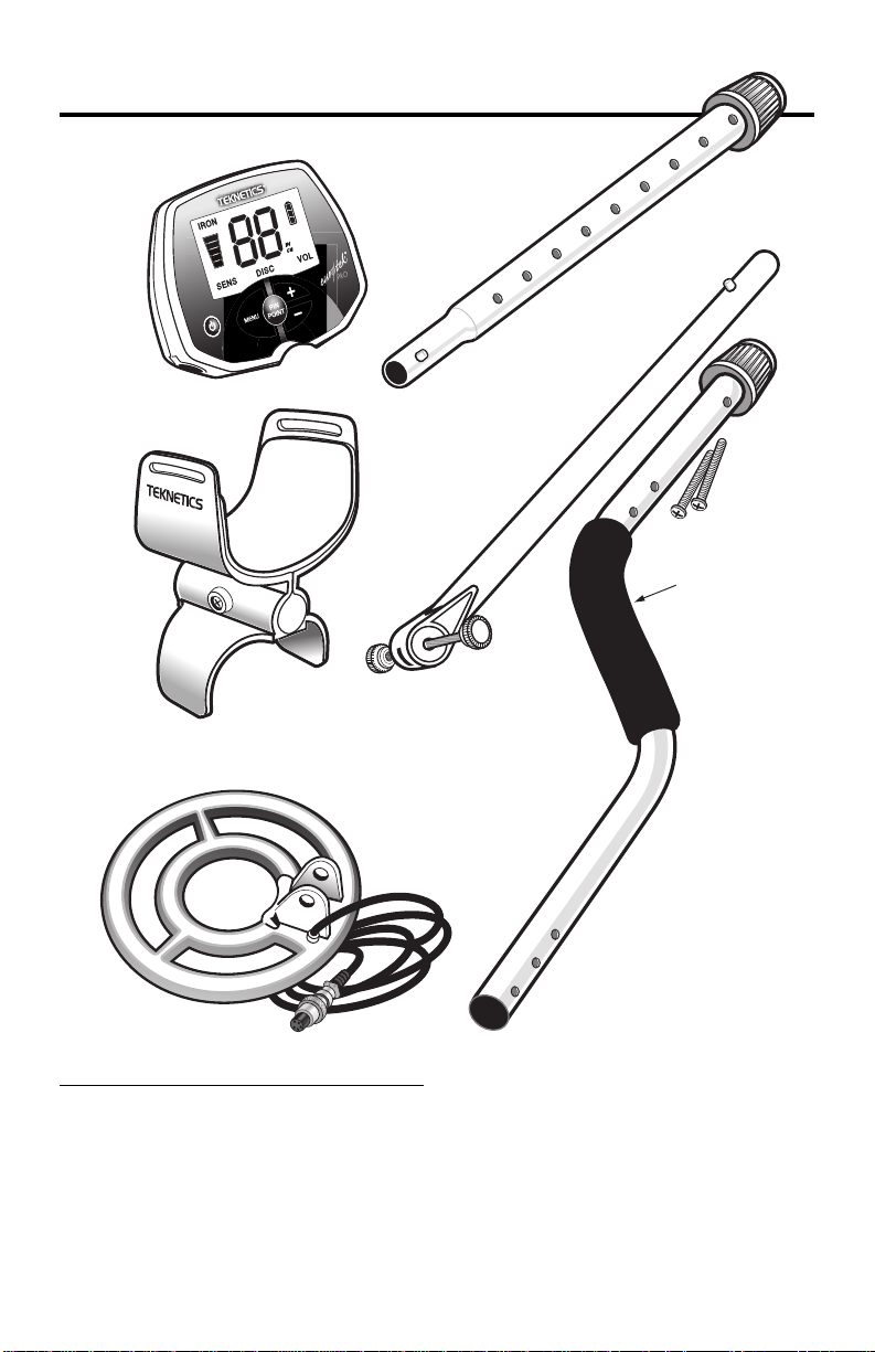
Unpack your detector to find the following contents:
4.Middle
Stem
1.Control Housing
2.Armrest Assembly with
Screw and Lock-Nut
3.Searchcoil
5. Lower Stem
with Bolt &
Knurled
Knob
attached
6.S-Rod with
2 Screws
(attached
with tape)
Tool Required: #1 Phillips Screwdriver
1. • Remove the Screw from the Armrest.
• Slide the Armrest over the end of the S-Rod.
• Attach with Screw and Lock-Nut.
2. Attach Control Housing with 2 screws; install back screw first.
NOTE: The Hand-grip fits under the Control Housing.
Peel back Hand-grip to expose the front hole.
4
Page 5
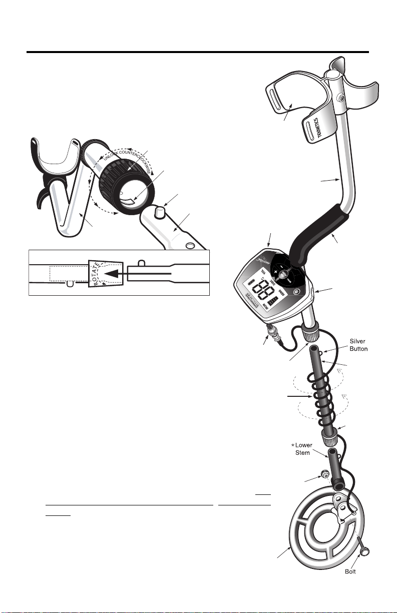
S-ROD
LOCKING
COLLAR
INTERNAL
CAM LOCK
SILVER BUTTON
MIDDLE
STEM
S-ROD
MIDDLE STEM
Hand-grip
Search
Coil
Cable
Cable
Plug
S-R
od
Middle
Stem
Locking
Collar
Locking
Collar
Knu
rled
Knob
Battery
Compartment
(ba
ck s
ide)
Headphone
Jack
Armrest
Sea
rch
oil
Caution:
ASSEMBLY
1 Position S-Rod upright.
●
2 Rotate the LOCKING COLLAR fully in the
●
Forcing in MIDDLE STEM with CAM LOCK raised may form a burr on
camlock. If this happens, remove burr with knife to allow insertion.
counterclockwise direction.
3 Insert your finger inside the tube and make sure the
●
INTERNAL CAM LOCK is flush with the inside of the
tube.
2
●
5
●
4
Insert the MIDDLE STEM into the S-ROD,
●
with the SILVER BUTTON pointed upward
5 Rotate the MIDDLE STEM until the SILVER
●
●
3
●
4
●
4
BUTTON locates in the hole.
6 T wist the LOCKING COLLAR fully in the clockwise
●
direction until it locks.
7 Repeat this process on the LOWER STEM.
●
8 Using the BOLT and KNURLED KNOB, attach the
●
SEARCHCOIL to the LOWER STEM.
9
Adjust the LOWER STEM to a length that lets you
●
maintain a comfortable upright posture, with your arm relaxed
at your side, and the SEARCHCOIL parallel to the ground in
front of you.
10
Wind the CABLE securely around the STEMS.
●
11
Connect CABLE PLUG to housing.
●
Do not twist the Cable or Plug. Turn Locking Ring only. Use
minimal finger pressure to start the threads. Do not crossthread. When the Locking Ring is fully engaged over the
threaded connector, give it a firm turn to make sure that it is
very tight. When the Locking Ring is fully engaged over the
threaded connector, it may not cover all of the threads.
12
Tighten both LOCKING COLLARS.
●
Note: Very tall users can purchase the optional Extended Lower Stem (TUBE5X), for extended reach.
*
5
Page 6
BATTERIES
Optional Arm Strap
The detector requires a single 9-volt ALKALINE battery (battery not included).
Do not use ordinary Zinc Carbon batteries.
Do not use “Heavy Duty” batteries.
Rechargeable batteries can also be used.
If you wish to use rechargeable batteries, we recommend using a
Nickel Metal Hydride rechargeable battery
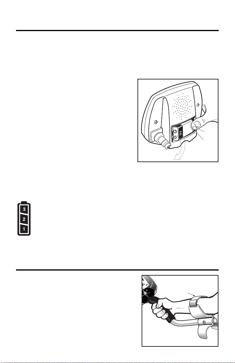
The battery compartment is located on the
back side of the housing.
Slide the battery door to the side and remove
it to expose the battery compartment.
For easy battery removal, push down firmly
on the bottom of the battery (see illustration).
BATTERY LIFE
Expect 20 to 25 hours of life from a 9-volt
alkaline battery.
Rechargeable batteries provide about 8
hours of usage per charge.
BATTERY INDICATOR
The battery icon at the top-right of the display has three vertical segments and
an outline segment.
The amount of battery voltage for an ALKALINE battery is indicated as follows:
3 vertical segments illuminated: 8.1 volts or more
2 vertical segments illuminated: 7.1 to 8.0 volts
1 vertical segment illuminated: 6.5 to 7.0 volts
No vertical segments illuminated: 6.2 to 6.4 volts
Outline Flashing: 6.1 volts or less
.
SPEAKER VOLUME AND BATTERY CHARGE
Y ou may notice the speaker volume drop while one battery segment is illuminated.
With the outline flashing, low speaker volume will be very apparent.
Armrest Strap (optional accessory)
The strap is available for purchase as a separate
accessory. Some users prefer to use the strap
when swinging the detector vigorously in order to
hold the detector secure against the arm.
The detector can also be used without the strap,
with no compromise to detector balance and
stability under most conditions.
6
Item # 2021112000
Page 7
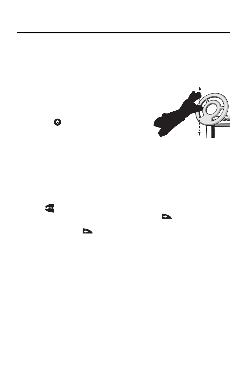
QUICK-START DEMONSTRATION
I. Supplies Needed
• a Nail • a Gold Ring (try several different size gold rings) • a Large Silver Coin
II. Position the Detector
a. Place the detector on a table, with the searchcoil hanging over the edge.
Or better, have a friend hold the detector, with the searchcoil off the ground.
b. Keep the searchcoil away from walls, floors and metal objects.
c. Remove watches, rings and jewelry.
d. Turn off lights or appliances, whose electromagnetic
emissions may cause interference.
e. Pivot the searchcoil back.
III. Power Up
Press .
IV. Wave each object over the searchcoil
a. Notice the tones and Target-IDs for each object (assumes default DISC
setting):
OBJECT TARGET-ID TONE
Nail lower (e.g. 10-35) LOW
Gold Ring medium (e.g.- Mid 50’s) V.C.O.
Larger Gold Ring medium (but higher than ID for smaller gold ring) V.C.O.
Silver Coin higher (e.g.- 80-99) High
b. Motion is required.
• Objects must be in motion over the searchcoil to be detected.
•
Sweep objects flat over the searchcoil, parallel to the plane of the searchcoil.
V.
Press twice to activate the DISC selection
a. While sweeping the Nail back-and-forth, press to
increase the DISC setting.
b. Continue to press and increase the DISC setting.
Notice that the Nail will be eliminated from detection at a certain DISC setting.
•
The nail is eliminated when the DISC setting is 40 numbers greater
than the target's ID.
Caution: Passing the nail at differing angles will yield different ID numbers.
• When the Nail is eliminated from detection, the IRON segment will still
flash but no tone will sound and no Target-ID will be indicated.
VI. Repeat Step V while waiving the Gold Ring, and then also
while waiving the Silver Coin
• Notice that the Gold Ring will be eliminated from detection.
• If the ID of the Silver Coin is greater than 80, then it will not be eliminated
from detection. But if the coin’s ID is less than 80, the tone will change
from V.C.O. to High Tone as DISC is adjusted.
VII. Press and hold PINPOINT
a. Hold a metal object motionless over the searchcoil.
b. Notice that motion is not required for detection.
c. Move the object closer, then farther away from the searchcoil.
• Notice the changing sound.
• Notice the changing depth values.
7
Page 8

0 10 20 30 40 50 60 70 80 90 99
EXAMPLES:
DISC = 0
HIGH
TONE
HIGH
TONE
DISC setting
DISC = 30
DISC = 55
DISC = 74
HIGH
TONE
30 69 99
DISC setting
V. C.O.
V. C.O.
0 69 99
HIGH
TONE
DISC eliminates targets
69 79 99
V. C.O.
DISC setting
DISC changes tone
from High to V.C.O.
DISC setting
V. C.O.
V. C.O.
V. C.O.
55 69 99
40 50 69 74 99
DISC = 79
DISC setting
40 50 69 79 99
TARGET I.D.
LOW
TONE
LOW
TONE
LOW
TONE
NO
TONE
NO
TONE
HIGH
TONE
HIGH
TONE
NO
TONE
NO
TONE
THE BASICS OF METAL DETECTING
This metal detector is intended for locating buried metal objects. When
searching for metals, underground or on the surface, you have the following
challenges and objectives:
1. Ignoring signals caused by ground minerals.
2. Ignoring signals caused by metal objects that you do not want to find, like
nails.
3. Identifying a buried metal object before you dig it up.
4. Estimating the size and depth of objects, to facilitate digging them up.
5. Eliminating the effects of electromagnetic interference from other
electronic devices.
Your metal detector is designed with these things in mind.
1. Ground Minerals
All soils contain minerals. Signals from ground minerals can interfere with
the signals from metal objects you want to find. All soils dif fer, and can differ
greatly , in the type and amount of ground minerals present. The Eurotek Pro
has a preset ground elimination setting. No user adjustments are required.
2. Trash
If searching for coins, you want to ignore items like aluminum foil and nails.
You can see the Target-ID value of the buried objects, listen to the sounds,
and then decide what you want to dig up. Or you can eliminate unwanted
metals from detection by using the DISCRIMINATION feature.
3. Identifying Buried Objects
Metal objects are identified by a 2-digit number on the display screen. This scale
has 99 points of resolution, and is an indicator of the relative electrical
conductivity of different objects. Higher numbers indicate more conductive
targets. Iron objects, which are usually of lesser value, display lower numbers.
Silver coins, for instance, usually display the highest numbers.
4. Size and Depth of Buried Objects
The 5-digit bar graph indicates the relative depth of a buried metal object.
This bar graph can indicate the relative size of different objects or their
distance from the searchcoil. For a given object, the more distance between
it and the searchcoil, the more bars illuminated. Amore accurate, and higher
resolution, depth reading is available when using the Pinpoint Mode. The
Pinpoint Mode does not require the searchcoil to be in motion to detect
metals. The ability to hold the searchcoil motionless over the target also aids
in tracing an outline of the buried object, or in pinpointing the exact location
of the object using techniques described in the pinpointing section of this
manual.
8
Page 9

SWIVEL
DOOR
THE BASICS OF METAL DETECTING
5. EMI (Electromagnetic Interference)
The searchcoil produces a magnetic field and then detects changes in that
magnetic field caused by the presence of metal objects. This magnetic field
that the detector creates is also susceptible to the electromagnetic energy
produced by other electronic devices. Cell phones, cell phone towers,
power lines, microwave ovens, lighting fixtures, TVs, computers, motors,
etc… all produce EMI which can interfere with the detector and cause it to
beep when no metal is present, and sometimes to beep erratically.
The SENSITIVITY control lets you reduce the strength of this magnetic field,
and therefore lessen its susceptibility to EMI. You may want to operate at
maximum strength, but the presence of EMI may make this impossible, so if
you experience erratic behavior or “false” signals,
reduce the sensitivity.
HEADPHONE JACK
Push the tab up and lock into place to
expose the headphone jack.
This detector has a 1/4” headphone jack.
It works with any stereo headphone that
has a 1/4” plug.
When the headphone jack is connected,
speaker volume is disabled.
USING HEADPHONES
Using a detector with headphones
facilitates detection of the weakest
signals and also extends the battery life.
It also allows you to hear subtle changes in the sound more clearly , particularly
if searching in a noisy location. For safety reasons, do not use headphones
near traffic or where other dangers are present. This device is to be used with
interconnecting cables/headphone cables shorter than three meters.
916
Page 10

OPERATION and CONTROLS
HOW TO WORK THE CONTROLS
Press or
to CHANGE
THE SETTING of the
active menu item.
The active menu item
is the highlighted
line on the bottom
of the display.
Press MENU
to select the
menu item
you want
to adjust.
POWER
ON/OFF
Press and hold
PINPOINT
to actuate
PINPOINT MODE
at any time.
POWERING UP
Press
The detector powers on.
A “ ” appears momentarily, indicating that the detector is in the
Discrimination Mode of operation.
All targets are detected. Motion is required.
Default sensitivity is 7, on scale of 1 to 10.
Default volume is 7, 70% of maximum.
10
Page 11

MENU SELECTIONS
Operational Overview
Press to activate the menu system: SENS, DISC or VOL.
At first activation of the menu system, the SENS menu selection appears.
Successive presses of will toggle through the menu selections.
With a menu selection visible, press or to change settings for that
menu selection.
When you reach the desired setting, as indicated by the 2-digit value on the
display, no further action is necessary.
• 4 seconds after the last or key-press, the menu icon will timeout and the last displayed setting will be programmed in.
• Or press again before the display times out, and advance to the next
menu selection; the last displayed setting will be programmed in.
During operation, recall the last menu selection by pressing MENU at any
time; the last menu selection adjusted will again be displayed.
While the MENU display is active, the LCD display will not respond to targets, but
the audio target system will continue to respond to any target or overload signal.
1. SENS (Sensitivity)
Press to illuminate the SENS menu icon.
Use and to increase or decrease sensitivity while SENS is
highlighted.
Maximum sensitivity setting is 10.
Minimum sensitivity setting is 1.
If the detector beeps erratically or beeps when there are no metal objects
being detected,
The searchcoil produces a magnetic field and then detects changes in that
magnetic field caused by the presence of metal objects. This magnetic field
that the detector creates is also susceptible to the electromagnetic energy
produced by other electronic devices. Cell phones, cell phone towers, power
lines, microwave ovens, lighting fixtures, TVs, computers, motors, etc…. all
produce EMI which can interfere with the detector and cause it to beep when
no metal is present, and sometimes to beep erratically.
reduce the sensitivity.
11
Page 12

MENU SELECTIONS
HOW DEEP WILL IT GO?
The Eurotek Pro Metal Detector will detect a coin-sized object to a distance of
about 24 cm (9.5”) from the searchcoil at maximum sensitivity. Large metal
objects can be detected to a depth of more than a meter. Detectability is directly
related to the size of the metal object -- the larger the object, the deeper it can
be detected.
Accuracy of target identification is also related to distance from the searchcoil.
Beyond a distance of 20 cm (8”), the accuracy of target identification begins to
diminish.
2. DISC (Discrimination)
The discrimination system in the Eurotek Pro is unlike systems in other metal
detectors.
Press to illuminate the DISC menu icon.
With each press of or , the DISC setting changes by one.
Press-and-Hold or to rapidly advance or reduce the DISC setting.
Target IDs from 1 to 69 can be eliminated from detection. Target IDs from 70 to
79 cannot be eliminated, but the user can change tones in this range.
See the DISCRIMINATION section of the manual for a complete description of
the DISC function.
12 13
Page 13

MENU SELECTIONS
3. VOL (Volume)
Press to illuminate the VOL menu icon.
The default volume setting is 7.
Press to increase speaker volume. Maximum volume is at setting 20.
Press to lower speaker volume. The minimum volume setting is 0, no
sound.
With volume set to 0, the Target-ID, Depth Bar Graph and Iron-Indicator will
function as normal, but the detector will not emit a sound when targets are
detected.
The overload volume signal will always sound off in the event of signal
overload, even with the volume set to 0.
Because the Eurotek Pro is so sensitive to even the smallest iron targets, the
detector incorporates a feature to reduce the volume of iron targets to
minimize user fatigue.
Volume settings 10 - 20 are available to control the volume level of iron
targets.
As you increase volume from 10 to 20, iron-volume changes from silent to
maximum. Note that, depending on the DISC setting, iron targets may
induce V.C.O. tones; in this case, the V.C.O. tones in the iron range (ID 1
- 40) will also have the same reduced volume.
At each of the 10 - 20 volume settings, nonferrous target response is maximum
volume.
Volume control applies only to motion target detection.
Volume changes do not affect the Pinpoint Mode volume, or the
keypad volume.
Volume Settings are as follows:
Volume Volume
Setting Nonferrous Ferrous Setting Nonferrous Ferrous
11 1 11101
2 2 2 12 10 2
3 3 3 13 10 3
4 4 4 14 10 4
5 5 5 15 10 5
6 6 6 16 10 6
7 7 7 17 10 7
8 8 8 18 10 8
9 9 9 19 10 9
10 10 0 20 10 10
Page 14

DISCRIMINATION SYSTEM
Target Detection
Sweep the detector back-and-forth
over the ground.
Keep the searchcoil parallel to the
ground as you sweep; do not lift the
searchcoil at the ends of your
sweeps.
Searchcoil motion is required for
target detection (except in Pinpoint
Mode).
CORRECT
WRONG
Target-ID
When objects are detected, the detector will emit a sound and a 2-digit TargetID will appear on the screen. Possible Target-IDs range from 1 to 99. This
number represents the electrical conductivity of the target detected; higher
numbers indicate more highly conductive targets.
The 2-digit number indicates the Target-ID of the last object detected. The
Eurotek Pro has a very fast target response and is able to detect different
objects in very close proximity. Therefore, the Target-ID displayed may change
rapidly as you sweep the searchcoil.
Three seconds after the last Target-ID is displayed, the Target-ID will time-out
and the number will disappear.
Bulgarian 10
stotinkas, 1999
50 kopeek
Nikolay II,1896,
Silver
14
Bulgarian 50
stotinkas,
1999 - 2007
5 kopeek,
Ekaterina II, 1781
Peter I, 1705,
Silver, 0.25 gr.
2 kopeek,
Alexander I, 1816
Mikhail
Fedorovich,
1613-1645
10 ct Napoleon III
(bronze, France)
Page 15

DISCRIMINATION SYSTEM
Target-ID (continued)
As a general reference, targets fall into the following ranges:
1 - 39 : iron
42 - 48 : foil and small gold nuggets
54 - 57 : gold nuggets, gold rings or targets containing mostly gold
87 - 89 : clad coins or coins of recent vintage
82 - 83 : copper coins
93 - 99 : larger silver coins
Note: There are a wide variety of metals and no target can be identified
for certain until unearthed. This table is for general reference only.
See the table on P. 18 for a more complete listing of Target-ID values for
common metal items.
3-Tone System
Depending on the type of metal detected, and the DISC setting of the detector,
a buried metal object will induce one of the following sounds:
No sound: metals eliminated from detection (or discriminated-out), with
the DISC function.
Low Tone: targets with an ID less than 40.
V.C.O. (variable pitch and volume):
-
targets with an ID between 40 and 69.
- targets between 70 and 79 when DISC setting is greater
than or equal to the Target-ID.
High Tone: - all targets with an ID of 80 or greater.
- targets with an ID between 70 and 79
if the DISC setting is less than the Target-ID.
Depending on where the user programs the DISC setting, a given target may
induce different tones.
15
Page 16

DISCRIMINATION SYSTEM
SWIVEL
DOOR
3-Tone System (continued)
The discrimination system in the Eurotek Pro is unlike systems in other metal
detectors.
• The default DISC setting is 0. When the detector is first powered on, all
targets are detected.
If the user saves different DISC settings (see Memory function, p. 21),
then this may change at power-up.
• As the DISC setting is adjusted, targets with IDs less than or equal to DISC
are eliminated from detection.
This target elimination scheme, common to many detectors, is
applicable to Target-IDs up to 69.
• For DISC settings greater than 69, targets in this range are not eliminated.
Rather, the tone changes from High Tone to V.C.O.
In this range, the DISC setting becomes the Variable Tone Breakpoint.
• The highest DISC setting possible is 79.
If the DISC setting is 79, then:
- all Target-IDs less than 70 are eliminated from detection
- all Target-IDs between 70 and 79 induce V.C.O. Tones.
- all Target-IDs greater than 79 induce a High Tone.
The Target-ID system and the Audio-ID systems on the Eurotek operate
independently. Therefore, there may be times when the tones and IDs seem
inconsistent. For example, a very deeply buried target may induce a low tone,
but the signal may be too weak for the visual ID system to determine, with
confidence, a reliable Target-ID number. In this case, the detector may not
register a visual Target-ID, even though the detector emits a tone.
1/4 of Stater,
gold, France
Double
Tournois,
copper
2 Franc Morlon,
aluminum
Roman
Nummus,
bronze
Medieval double
sol
Celtic Potin,
mixed metal
50cent Chambre
du Commerce
Merovingian
Triens, gold
Page 17

0 10 20 30 40 50 60 70 80 90 99
EXAMPLES:
DISC = 0
HIGH
TONE
HIGH
TONE
DISC setting
DISC = 30
DISC = 55
DISC = 74
HIGH
TONE
30 69 99
DISC setting
V. C.O.
V. C.O.
0 69 99
HIGH
TONE
DISC eliminates targets
69 79 99
V. C.O.
DISC setting
DISC changes tone
from High to V.C.O.
DISC setting
V. C.O.
V. C.O.
V. C.O.
55 69 99
40 50 69 74 99
DISC = 79
DISC setting
40 50 69 79 99
TARGET I.D.
LOW
TONE
LOW
TONE
LOW
TONE
NO
TONE
NO
TONE
HIGH
TONE
HIGH
TONE
NO
TONE
NO
TONE
DISCRIMINATION SYSTEM
Below is an illustration of how the DISC control and Variable Tone Breakpoint
operate:
17
Page 18

DEPTH INDICATOR
In Discrimination Mode, each time an object is detected, a Bar Graph
illuminates in addition to the Target-ID.
The Bar Graph is a graphic representation of the distance from the searchcoil,
and is calibrated to a coin-sized object.
• More bars indicate a deeper object.
• Fewer bars indicate a shallower object.
The scale for coin-sized objects, with sensitivity at maximum, is
:
Display:
Depth:
>20cm 15cm-20cm 10cm-15cm 6cm-10cm <6cm
(8”)* (6”-8”) (4”-6”) (2.5”-4”) (2.5”)**
* 5 Bars: If the object is a coin, it is deeply buried.
…or this could be the faint signal from a large, but very deeply buried,
object.
** 1 Bar: If the object is a coin, it is shallow.
…or this could be a large object more deeply buried.
Target-ID Coin Reference. Below are known Target-IDs for some reference coins:
Merovingian Triens (gold, France) 42
Polish Zloty (Pre-WWII) 0.20 zl (1923 nickel) 44-99
Celtic Potin (copper+lead) 52
Polish Zloty 0.50PLN 54-56
USSR 50 kopeek, 1980, Nickel, D 24 mm. 56
Russian Scale Peter I, 1705, Silver, 0.25 gr. 56-57
Polish Zloty 1PLN 56-57
US Nickel 56-57
Polish Zloty PRL 100zl (CuNi) 58-59
Bulgarian 1 stotinkas, 1999 (CuAlNi) 58-64
Bulgarian 10 stotinkas, 1999 59-60
Bulgarian 50 stotinkas, 1999,2004,2005,2007 59-65
Roman Nummus (bronze) 60
1/4 of Stater (gold, France) 60
50cent Chambre du Commerce (France) 60
Bulgarian 2 stotinkas, 1999 (CuAlNi) 60-64
Polish Zloty 5PLN 61
2 Euro Coin 62-66
Polish Zloty '0.05PLN 63-64
British 20p 64-65
Polish Zloty 2PLN 64-65
USSR, 5 kopeek, 1961, Bronze, D 25 mm. 65
18
Russian Scale Mikhail Fedorovich, 1613-1645, Silver, 0.625 gr. 65
Bulgarian 5 stotinkas (old) (CuAlNi) 68-73
Bulgarian 1 lev 69-73
10 Euro Cent 70-74
1 Euro Coin 70-78
Medieval double sol coin (France) 75
20 Euro Cent 76-78
50 Euro Cent 76-80
Double Tournois (copper, France) 78
British £1 79-80
Polish Zloty PRL .20 zl (aluminum) 80
10 ct Napoleon III (bronze, France) 80
British £2 81
2 Franc Morlon (Aluminum, France) 82
US Dime 84-85
Polish Zloty (Pre-WWII) 2zl (1933 silver) 86-87
US Quarter 88-90
Russian, 50 kopeek Nikolay II,1896, Silver, D 27 mm. 93-94
US Silver Dollar 94-95
Russian, 2 kopeek, Alexander I, 1816, Copper, D 30 mm. 94-95
Russian, 1 ruble Nikolay II,1896, Silver, D 34 mm. 98
Russian, 5 kopeek, Ekaterina II, 1781, Copper, D 41 mm. 99
Page 19

MODE SELECTIONS
IRON IDENTIFICATION
Variable Iron Identification & Discrimination
The Eurotek Pro allows the user not only to discriminate iron targets, but
classifies them by size and signal strength. Ferrous objects will have a
ID between 1 and 39.
To eliminate all ferrous objects from detection, set DISC = 39.
Alternatively , the user can selectively eliminate ferrous objects less than a given
Target-ID. For example, to eliminate ferrous objects with an ID of less than 15,
choose a DISC setting of 14.
Volume settings 10-20 also allow the user to change the volume response of
ferrous metals.
Iron-Indicator
The IRON icon flashes momentarily when ferrous objects are present.
The IRON icon flashes independent of the discrimination setting.
cannot disable this icon.
Relic hunters will frequently seek out iron-laden sites as good prospective
treasure-hunting sites. The Eurotek Pro Iron-Indicator is intended for this
purpose. The indicator alerts the user to the presence of iron, even if iron has
been discriminated out. Relic hunters can search free of iron-target audio, yet
still be alerted to the presence of ferrous objects.
Target-
The user
PINPOINT MODE
Press-and-hold to enter the no-motion Pinpoint Mode of operation.
“PP” is momentarily displayed on the screen.
In Pinpoint Mode:
• No searchcoil motion is required.
Any metal object in the searchcoil's field of detection will induce an audible
hum, regardless of whether the searchcoil is in motion or motionless.
• Target-ID is not possible.
• Discrimination is not possible.
All metal targets are detected, regardless of the DISC setting.
• Audio feedback is V.C.O.
All targets induce V.C.O. audio, regardless of the DISC setting.
• Target depth is displayed.
Pinpoint is typically used to precisely identify the location of an object previously
detected in the Discrimination Mode.
The Pinpoint Mode can also be useful in tracing the outline of larger objects. Since
searchcoil motion is not required, very slow movement around an object can
reveal an outline of its shape.
While not intended as a continuous-search mode, Pinpoint can be used in this
fashion if the user keeps the button depressed.
19
Page 20

MODE SELECTIONS
Pinpoint Mode (continued)
If used for continuous-search, be aware that the signal is subject to drift with
both time and temperature change. Drift will cause either an increase or
decrease in sensitivity
until the detector sounds of
Pinpoint Depth Indicator
While is depressed, a 2-digit number indicates the depth of the target. This
depth indicator is calibrated to a coin-sized object.
CM or 09IN, may display in the event of electrical noise or a very weak signal.
25
T
o demonstrate the depth indicator function, hold a coin over the searchcoil,
press-and-hold and then move a coin toward and away from the searchcoil.
Hold the coin flat, parallel to the searchcoil. W
as the distance from the searchcoil changes.
Pinpoint Retuning
Retuning in the Pinpoint Mode is useful in narrowing down the location of a target.
T
o retune the detector, quickly release the button and immediately depress the
button again.
When the user releases ,“ ” is displayed momentarily on the screen. The
“
” indicates that the detector is retuning to the incoming signal level.
How to Pinpoint
Position the searchcoil 2 to 5 cm (1”-2”) above the ground, and to the side of the
target.
and the sound will communicate the target’
side, and hear no sound at the ends of the sweep, the target is located in the middle
of that zone, where the sound is loudest. If the sound is loud over a wide area, the
buried object is large. Use Pinpoint to trace an outline of such large objects.
Then press and hold . Now move the searchcoil slowly across the target,
. In the most extreme case, the signal will drift upward
f continuously with no target present.
The maximum depth reading,
atch the depth indicator change
s location. As you sweep from side to
Narrow It Down
To further narrow the field of detection, position the searchcoil near the center
of the response pattern (but not at the exact center), release
quickly press-and-hold it again. Now you will only hear a response when the
searchcoil is right over the top of the target. Repeat this procedure to narrow
the zone even further
will narrow further.
Consider Purchasing a Pinpointer
When you kneel down to unearth an object, you may find it frustrating as the object
can appear exactly like the surrounding soil. You may hold the object in your hand,
and find it necessary to pass a handful of dirt over the searchcoil to see if it contains
metal. An easier way is to use a handheld pinpointer . It is a probe-like device which
is poked into the ground, making close up pinpointing a snap, reducing digging
time, and minimizing the size of the holes you will dig. Teknetics offers a robust and
inexpensive pinpointer designed for this purpose.
20
. Each time you repeat the procedure, the field of detection
, and then
Page 21

OTHER FEATURES
Overload Warning
If a metal object or highly magnetic soil are too close to the searchcoil, the
detector will “overload.”
“ ” will appear on the screen and the detector will make a rapid, repeating
mid-tone warning sound.
Overload will not harm the detector, but the detector will not function under
these conditions.
Raise the searchcoil to search at a greater distance, or move to a different location.
Unit of Measure (U/M)
The depth indicator in Pinpoint Mode can display either centimeters (CM) or
inches (IN).
The default unit of measure is centimeters (CM).
To change the unit of measure:
1. Start with the detector turned OFF.
2. Press-and-hold .
3. Press .
Continue to hold down .
4. Quickly release and then immediately press-and-hold again to toggle
between CM and IN.
5. When the desired U/M appears on the screen, release .
The detector will now operate with the desired U/M, even after the detector
has been powered down.
To change the U/M again, repeat the procedure.
Memory
To store the current settings (SENS, DISC and VOL):
1. Start with the detector turned ON.
2. Select all desired settings.
3. Press-and-hold for 8 seconds.
4. When the three menu selections appear at the bottom of the screen,
release .
When you turn the detector ON for future use, your detector will resume
operation with your programmed settings.
Reset
To return all detector settings to the factory defaults:
1. Start with the detector turned OFF.
2. Press-and-hold .
3. Press .
4. Release .
The 2-digit number displayed is the software revision number.
21
Page 22

TROUBLESHOOTING
TROUBLESHOOTING GUIDE
SYMPTOM CAUSE SOLUTION
Detector chatters • Using detector • Use detector
or beeps erratically indoors outdoors only
• Using detector near • Move away
power lines
• Using 2 detectors in • Keep 2 detectors
close proximity at least 6 meters
• Highly oxidized • Only dig up
buried object repeatable signals
• Environmental •
electromagnetic until erratic
interference signals cease
from power lines
(20’) apart
Reduce sensitivity
Constant low tone •
or
constant repeating
tones
Discharged battery
• Replace battery
• Wrong type of • Use only 9V
battery alkaline battery
LCD does not lock • Multiple targets •
Move coil slowly
on to one Target-ID present at different angles
or detector emits •
Highly oxidized target
multiple tones • Sensitivity set • Reduce sensitivity
too high
No power, no sounds
• Dead battery • Replace battery
• Cord not connected •
Check connections
securely
Note: This equipment has been tested and found to comply with the limits for a Class B digital device,
pursuant to part 15 of the FCC Rules. These limits are designed to provide reasonable protection
against harmful interference in a residential installation. This equipment generates uses and can radiate
radio frequency energy and, if not installed and used in accordance with the instructions, may cause
harmful interference to radio communications. However, there is no guarantee that interference will not
occur in a particular installation. If this equipment does cause harmful interference to radio or television
reception, which can be determined by turning the equipment off and on, the user is encouraged to try
to correct the interference by one or more of the following measures:
- Reorient or relocate the receiving antenna.
- Increase the separation between the equipment and receiver.
- Consult the dealer or an experienced radio/TV technician for help.
The manufacturer declares that the minimum ESD performance criteria is 1) the unit shall not be
permanently damaged and 2) operator intervention is allowed.
This product meets the requirements of Industry Canada: CAN ICES-3 B/NMB-3 B.
CE
22
Page 23

ACCESSORIES
Teknetics® Padded Carrying Bag
.
Made of rugged double-stitched nylon construction.
Includes handy outside zip-pocket for extra batteries or
small accessories. – CBAG-T
Teknetics® Camo Pouch
Camo pouch with two inside pockets, belt included. -
PCH-T
Teknetics® Stereo Headphones
Use with Teknetics® metal detectors with true stereo. Utilizes 1/4-inch stereo
& 1/8-inch plug. Compatible with all Teknetics
®
models with 1/4-inch &
1/8-inch jacks. –HEADT
Arm Strap
Secure your detector to your arm for a perfect swing
– 2021112000
Teknetics® Pinpointer
Pinpoints the exact location of buried metal objects. Audio signal indicator
and vibrator. No assembly required, runs on (1) 9-Volt
Battery
.
–PINPOINTER
Digging Trowel
One-piece stainless steel construction with depth gauge
- TROWEL-2
Gold Pick
Tem pered steel head is 10” long and the edge is 3 1/4” wide. The overall
length is 19” with a durable fiberglass handle and a
rubberized hand grip.
Includes a powerful magnet attached to the head
to quickly discriminate iron targets and magnetic hot rocks. –
GOLDPICK
Lesche Knife
Made from high quality heat-treated tempered steel. The ultimate
digging tool. Comes with a durable sheath.
12" in length with a 7" serrated blade -
LESCHE KNIFE
Eurotek® T-Shirt
100% cotton with Erotek® Logo. Sizes LG, XL & XXL
-
ETPSHIRT
Eurotek® Baseball Cap
One size fits all -
ETPCAP
Rain Cover
Custom made to protect from weather
-RAINCOV-ET
Extended Lower Stem
For taller users
-TUBE5X
(image not shown)
Replacement & Accessory Searchcoils
and Protective Covers
Searchcoil Protective Cover
Item# Description Item#
5COIL-TEK Searchcoil, 5"DD Round, closed 5COVER-CZ3
8COIL-7TEK * Searchcoil, 8" Concentric, open 8COVER-7
10COIL-TEK Searchcoil, 10" Concentric, open F70COVER
10COILDD-TEK Searchcoil, 10"DD Ellipse, closed 2023190000
11COIL-TEK ** Searchcoil, 11"DD Ellipse, open COVER-11DD
* standard with detector
** standard with Eurotekpro-11DD
23
Page 24

®
TREASURE HUNTER’S CODE OF ETHICS:
• Always check Federal, State, County and local laws before searching.
• Respect private property and do not enter private property without the owner’s permission.
• Take care to refill all holes and leave no damage.
• Remove and dispose of any and all trash and litter found.
• Appreciate and protect our inheritance of natural resources, wildlife and private property.
•
Act as an ambassador for all treasure hunters; use thoughtfulness, consideration and courtesy at all times.
• Never destroy historical or archaeological treasures.
• All treasure hunters may be judged by the example you set; always conduct yourself with
courtesy and consideration of others.
5-YEAR LIMITED WARRANTY
The Eurotek®Pro metal detector is warranted against defects in materials and
workmanship under normal use for five years from the date of purchase to the
original owner.
Damage due to neglect, accidental damage or misuse of this product is not
covered under this warranty. Decisions regarding abuse or misuse of the detector
are made solely at the discretion of the manufacturer.
Proof of Purchase is required to make a claim under this warranty.
Liability under this Warranty is limited to replacing or repairing, at our option, the
metal detector returned, shipping cost prepaid, to First Texas Products. Shipping
cost to First Texas Products is the responsibility of the consumer.
To return your detector for service, please first contact First Texas Products for a
Return Authorization (RA) Number. Reference the RA number on your package and
return the detector within 15 days of calling to:
First Texas Products L.L.C.
1465-H Henry Brennan Dr.
El Paso, TX 79936
Phone: 915-633-8354
NOTICE TO CUSTOMERS OUTSIDE THE U.S.A.
This warranty may vary in other countries; check with your distributor for details.
According to FCC part 15.21, changes or modifications made to this device not expressly approved by
the party responsible for compliance could void the user’s authority to operate this equipment.
METPRO Rev.2 041213
Warranty does not cover shipping costs to and from the U.S.A.
Copyright©2013 by First Texas Products, L.L.C.
All rights reserved, including the right to reproduce this book, or parts thereof, in any form,
Operational Weight: 1.077 kg (2lbs 6oz), with 11DD coil: 1.19 kg (2lbs 10oz)
1465-H Henry Brennan • El Paso, TX 79936 • (915) 633-8354
except for the inclusion of brief quotations in a review.
Published by First Texas Products, L.L.C.
www.tekneticst2.com
 Loading...