

Page 1
TB-1016-A
Replaces TB-1016
Technical Bulletin
Professional Gravity
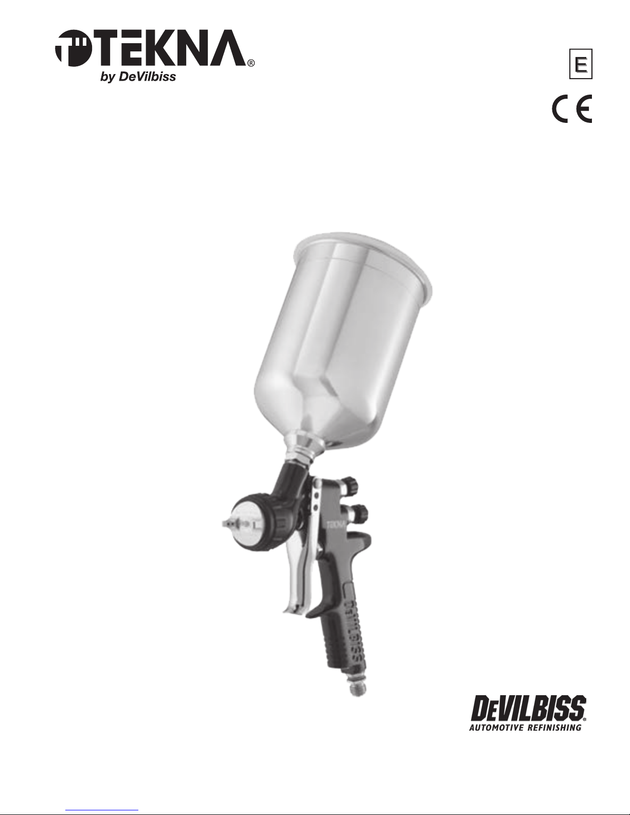
Feed Spraygun
Gun Repair Kit
No. 702736
800.445.3988
www.autorenishdevilbiss.com
Page 2

TB-1016-A
Table of Contents
Topic Page
EC Declaration of Conformity .................................................................................................................................3
Operational Description
Construction Features, Materials of Construction,
Specications & Technical Data
Safety Precautions
Installation, Operation, Preventive Maintenance & Cleaning,
Spray Gun Lubrication
Parts Replacement/Maintenance
A. Servicing Air Valve
B. Replacing Air Valve
C. Needle Packing, Fluid Insert, Spreader Valve Assembly
D. Air Separator Seal
E. Chart 1 – Air Caps
Chart 2 – Fluid Nozzles & Fluid Needles
F. Exploded View and Parts List
Troubleshooting Possible Problems in Operation
Accessories
Warranty
................................................................................................................................................................... 14
......................................................................................................................................................................... 15
............................................................................................................................................3
.................................................................................... 4
....................................................................................................................................................... 5
.............................................................6
..............................................................................................................7–12
.................................................................................................................................... 7
................................................................................................................................... 8
...................................................... 9
................................................................................................................................. 10
................................................................................................................................. 11
.......................................................................................................... 12
............................................................................ 13–14
When used with the HVLP cap, this gun can be used anywhere—both in mandated HVLP and unregulated areas.
When used with the High Efciency cap, this gun can be
used in unregulated areas and certain approved regulated
areas. See www.autorefinishdevilbiss.com for a complete
listing of approved areas and requirements for regulatory
compliance.
Consult your local air quality management agency with any
questions regarding HVLP or compliance requirements in
your area.
2
NOTE:
Page 3
Technical Bulletin
TEKNA Gravity Feed Spraygun
IMPORTANT: Read and follow all instructions and Safety Precautions before using this equipment. Keep
for future use.
EC Declaration of Conformity
We, Finishing Brands UK, Ltd., Ringwood Rd, Bournemouth, Dorset, BH11 9LH, UK, as the manufacturer of the
Spray gun model TEKNA, declare, under our sole responsibility, that the equipment to which this document
relates is in conformity with the following standards or other normative documents:
BS EN 12100 PARTS 1 & 2: 2010, BS EN 1953: 1998+A1:2009; and thereby conform to the
protection requirements of Council Directive 98/37/EEC relating to Machinery Safety Directive, and;
EN 13463-1:2009, council Directive 94/9/EC relating to Equipment and Protective Systems intended
for use in Potentially Explosive Atmospheres protection level II 2 G X.
This product also complies with the requirements of the EPA guidelines, PG6/34. Transfer efciency certicates
are available on request.
TB-1016-A
D Smith, General Manager
June 2013
The TEKNA Gravity Feed Spraygun Kit complies to ATEX regulations 94/9/EC, protection level II 2 G X, Suitable for
use in Zones 1 and 2.
DeVilbiss Automotive Renishing reserves the right to modify equipment specication without prior notice.
Operational Description
The TEKNA spraygun is a lightweight professional gun designed to handle both water-based and solvent-based
coating materials. Both HVLP and high efciency models are available.
High volume, low pressure (HVLP) models are designed to reduce overspray and provide maximum transfer
efciency by limiting air cap pressure to 0.7 bar (10 psi) (complies with rules issued by SCAQMD and other air
quality authorities).
HVLP models will produce approximately 0.7 bar (10 psi) air cap pressure at 1.8 bar (26 psi) gun inlet pressure
with the trigger pulled. HVLP air cap #202 is designed for optimum basecoat applications. HVLP air cap #909
is designed for optimum clear coat applications. Two air cap test kits are available (see Accessories) which can
be utilized to set the exact air cap pressure.
High efciency models use air cap #7E7. These models are designed to provide optimum atomization of
virtually all waterborne or solvent-based common coating materials at increased application rates while
maintaining very high transfer efciency. High efciency models, when tested under recommended conditions
with automotive renishing materilas, have been found to exceed 65% transfer efciency.
High efciency models comply with SCAQMD rules and certain other air quality authorities. Refer to the website
www.autorefinishdevilbiss.com for a complete listing of approved areas and requirements for regulatory
compliance.
IMPORTANT: These guns are not designed for use with highly corrosive and/or abrasive materials and if
used with such materials it must be expected that the need for cleaning and/or replacement of parts will be
increased. If there is any doubt regarding the suitability of a specic material, contact your TEKNA Distributor or
TEKNA direct.
NOTE: This gun is not to be used with halogenated hydrocarbon solvents or cleaning agents such as
1,1,1,-Trichloroethane or methylene chloride. These solvents can react with the aluminium components
used in this gun and cup. The reaction can become violent and lead to an equipment explosion.
3
Page 4
TB-1016-A
1
3, 4, 12
2
16
15
5
9
10
11
7
8
17
14
13
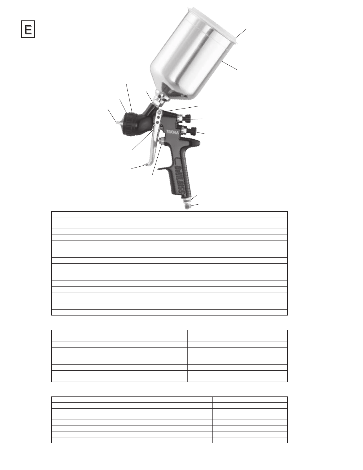
Construction Features
1 Air Cap (nickel plated brass for long durability)
2 Air Cap Retaining Ring (allows easy rotation of air cap)
3 Fluid Nozzle (not visible, ideal for automotive topcoat systems)
4 Fluid Needle (not visible)
5 Fluid Inlet (3/8 BSP thread – accepts TEKNA & DeVilbiss cups)
6 Air Inlet (universal thread, accepts G 1/4 & 1/4 NPS)
7 Self Adjusting Needle Packing (packing not visible, for long packing life)
8 Trigger (ergonomic for comfort)
9 Trigger Stud & Screw (easy replacement design)
10 Fan Air Adjustment (stepless regulation for at to round spray)
11 Fluid Adjustment (stepless regulation of uid volume)
12 Removable Air Separator (not visible, for long gun service life)
13 Interchangeable Colour ID System (4 coloured rings supplied)
14 Forged gun body (ergonomic, good looking & durable, easy to clean)
15 900cc Aluminium Cup (easy clean) (shown) or 20 oz. Acetal Cup (waterbourne) (not shown)
16 Push On Lid w/Drip Free Vent (disposable/easy clean design) (aluminum cup) or screw-on lid w/vent (acetal Cup)
17 Air Valve (design offers low pull force & low pressure drop)
18 Gun acceptable for waterborne and solvent borne applications
6
Materials of Construction
Gun Body Anodized aluminium
Air Cap Nickel plated brass
Fluid Nozzle, Fluid Needle, Fluid Inlet, Trigger Stud Stainless steel
Air Separator, Air Cap Retaining Ring, Knobs Anodized aluminium
Springs, Clips, Screws Stainless steel
Seals, Gaskets Solvent resistant
Trigger Chrome plated steel
Handle Plug, Air Inlet, Body Bushing, Spreader Valve Body, Air Valve Nut Chrome plated brass
Air Valve Assembly Stainless steel, acetal
Specifications & Technical Data
Air Supply Connection Universal 1/4" BSP and 1/4" NPS
Maximum Static Air Inlet Pressure P1 = 12 bar (175 psi)
Nominal Gun Air Inlet Pressure for HVLP Models (with gun triggered) 1.8 bar (26 psi)
Nominal Gun Air Inlet Pressure for High Efciency Models – (with gun triggered) 1.5 bar (22 psi) (for compliance)
Air Consumption See Chart 1 on page 11
Fluid Supply Connection 3/8" BSP
Service Temperature 0 to 40°C (32 to 100°F)
Gun Weight (gun only) 478g (16.9 oz.)
4
Page 5
TB-1016-A
PROP 65 WARNING
WARNING: This product contains
chemicals known to the State of
California to cause cancer and birth
defects or other reproductive harm.
Safety Precautions
CA PROP
65
This bulletin contains information that is important for you to know and understand. This information relates to USER SAFETY and PREVENTING EQUIPMENT PROBLEMS. To help you recognize this information, we use the following symbols. Please pay particular attention to
these sections.
NOTE
Important safety information – A hazard that may
cause serious injury or loss of life.
WARNING
CAUTION
Important information that tells how to prevent damage
to equipment, or how to avoid a situation that may cause
minor injury.
Information that you should pay special attention to.
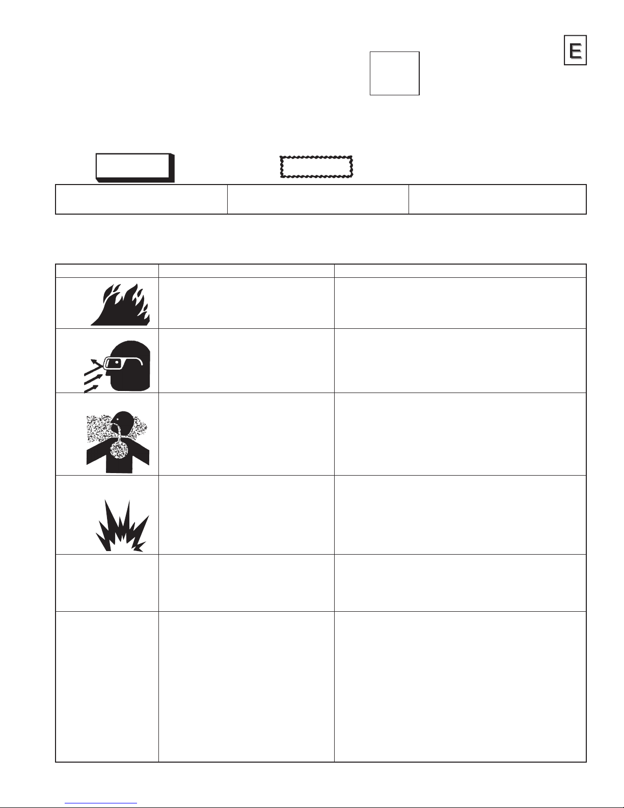
The following hazards may occur during the normal use of this equipment. Please read the following chart before using
this equipment.
HAZARD CAUSE SAFEGUARDS
Fire
Solvent Spray
Solvent and coatings can be highly ammable or
combustible especially when sprayed.
During use and while cleaning and ushing, solvents
can be forcefully expelled from uid and air passages.
Some solvents can cause eye injury.
Adequate exhaust must be provided to keep air free of accumulations of
ammable vapours.
Smoking must never be allowed in the spray area.
Fire extinguishing equipment must be present in the spray area.
Wear eye protection.
Inhaling Toxic Substances
Explosion Hazard –
Incompatible Materials
General Safety
Cumulative Trauma disorders
(“CTD’s”)
CTD’s, or musculoskeletal
disorders, involve damage
to the hands, wrists, elbow,
shoulders, neck and back.
Carpal tunnel syndrome
and tendonitis (such as
tennis elbow or rotator
cuff syndrome) are examples
of CTD’s.
Certain materials may be harmful if inhaled, or if there
is contact with the skin.
Halogenated hydrocarbon solvents – for example;
methylene chloride and 1,1,1,-Trichloroethane are
not chemically compatible with the aluminium that
might be used in many system components. The
chemical reaction caused by these solvents reacting
with aluminium can become violent and lead to an
equipment explosion.
Improper operation or maintenance of equipment. Operators should be given adequate training in the safe use and maintenance of
Use of hand tools may cause cumulative trauma
disorders (“CTD’s”).
CTD’s, when using hand tools, tend to affect the upper
extremities. Factors which may increase the risk of
developing a CTD include:
1. High frequency of the activity.
2. Excessive force, such as gripping, pinching,
or pressing with the hands and ngers.
3. Extreme or awkward nger, wrist, or
arm positions.
4. Excessive duration of the activity.
5. Tool vibration.
6. Repeated pressure on a body part.
7. Working in cold temperatures.
CTD’s can also be caused by such activities as sewing,
golf, tennis, and bowling, to name a few.
Follow the requirements of the Material Safety Data Sheet supplied by your
coating material manufacturer.
Adequate exhaust must be provided to keep the air free of accumulations of toxic
materials.
Use a mask or respirator whenever there is a chance of inhaling sprayed
materials. The mask must be compatible with the material being sprayed and
its concentration. Equipment must be as prescribed by an industrial hygienist or
safety expert, and be NIOSH approved.
Guns with stainless steel internal passageways may be used with these solvents.
However, aluminium is widely used in other spray application equipment – such
as material pumps, regulators, valves, and cups. Check all equipment items
before use and make sure they can also be used safely with these solvents.
Read the label or data sheet for the material you intend to spray. If in doubt as to
whether or not a coating or cleaning material is compatible, contact your material
supplier.
the equipment (in accordance with the requirements of NFPA-33, Chapter 15).
Users must comply with all local and national codes of practice and insurance
company requirements governing ventilation, re precautions, operation,
maintenance, and housekeeping. These are OSHA Sections 1910.94 and
1910.107 and NFPA-33.
Pain, tingling, or numbness in the shoulder, forearm, wrist, hands, or ngers,
especially during the night, may be early symptoms of a CTD. Do not ignore
them. Should you experience any such symptoms, see a physician immediately.
Other early symptoms may include vague discomfort in the hand, loss of
manual dexterity, and nonspecic pain in the arm. Ignoring early symptoms and
continued repetitive use of the arm, wrist, and hand can lead to serious disability.
Risk is reduced by avoiding or lessening factors 1-7.
5
Page 6
TB-1016-A
INSTALLATION
For maximum transfer efciency, do not use more pressure than
is necessary to atomise the material being applied.
1. Connect the gun to a clean, moisture and oil free air
supply using a hose size of at least 8 mm (5/16") I.D. hose.
Do not use 6 mm I.D. hose (8 m x 6 mm hose at 510 LPM
has a pressure loss of 1.8 bar. 8 m x 8 mm hose at 510 LPM
has a pressure loss of 0.6 bar. [Do not use 1/4" I.D. hose
(25' x 1/4" hose at 18 CFM has a pressure loss of 25 psi.
25' x 5/16" hose at 18 CFM has a pressure loss of 8 psi).]
Depending on hose length, larger I.D. hose may be required.
NOTE
When gun is triggered on, adjust inlet air pressure
(for recommended pressures see Chart 1 under Parts
Replacement) at the gun inlet. (Pressure gauge shown under
Accessories is recommended for this). Do not use more
pressure than is necessary to atomise the material being
applied. Excess pressure will create additional overspray and
reduce transfer efciency.
NOTE
If quick connects are required, use only high ow quick con-
nects approved for HVLP use. Other types will not ow enough
air for proper gun operation.
NOTE
If an air adjusting valve is used at the gun inlet, use a DeVilbiss air
adjusting valve. Some competitive adjusting valves have signicant pressure drop that can adversely affect spray performance.
DeVilbiss air adjusting valves have minimal pressure drop.
2. Attach the gravity feed cup to the material inlet.
NOTE
Protective coating and rust inhibitors have been used
to keep the gun in good condition prior to shipment.
Before using the gun, ush it with solvents so that these
materials will be removed from uid passages.
OPERATION
1. Mix coating material to manufacturer’s instructions and strain
material.
2. Fill the cup with the required amount of material.
Fill to no more than 19 mm (3/4") from the top of the cup.
DO NOT OVERFILL.
3. Attach Cup Lid.
4. Turn uid adjusting knob (18) clockwise to prevent uid
needle movement.
5. Turn spreader valve adjusting knob (23) counter clockwise to
fully open.
6. Trigger gun on and adjust inlet air pressure (for
recommended gures see Chart 1 under Parts Replacement)
at the gun inlet. (Pressure gauge shown under Accessories is
recommended for this).
7 Turn uid adjusting knob counter clockwise until rst
thread shows.
8. Test spray. If the nish is too dry, reduce airow by reducing
air inlet pressure.
9. If nish is too wet, reduce uid ow by turning uid adjusting
knob (18) clockwise. If atomisation is too coarse, increase inlet
air pressure. If too ne, reduce inlet pressure.
10. The pattern size can be reduced by turning spreader valve
adjusting knob (23) clockwise.
11. Hold gun perpendicular to surface being sprayed. Arcing
or tilting may result in uneven coating.
12. The recommended spray distance is 150-200 mm (6"–8").
13. Spray edges rst. Overlap each stroke a minimum of 75%. Move
gun at a constant speed.
14. Always turn off air supply and relieve pressure when gun is not
in use.
PREVENTIVE MAINTENANCE & CLEANING
To clean air cap and uid nozzle, brush exterior with a stiff bristle
brush. If necessary to clean cap holes, use a broom straw or
toothpick if possible. If a wire or hard instrument is used, extreme
care must be used to prevent scratching or burring of the holes which
will cause a distorted spray pattern.
To clean uid passages, remove excess material from cup, then ush
with a suitable solvent. Wipe gun exterior with a solvent dampened
cloth. Never completely immerse in solvent as this is detrimental to
the lubricants and packings.
NOTE
When replacing the uid nozzle or uid needle, replace both
at the same time. Using worn parts can cause uid leakage.
See page 11, Chart 2. Also, replace the needle packing at this
time. Lightly lubricate the threads of the uid nozzle before
reassembling. Torque to 18–20 nm (13–15 ft-lbs). Do not over
tighten the uid nozzle.
CAUTION
To prevent damage to uid nozzle (8) or uid needle (15), be
sure to either 1) pull the trigger and hold while tightening or
loosening the uid nozzle, or 2) remove uid adjusting knob (18)
to relieve spring pressure against needle collar.
SPRAY GUN LUBRICATION
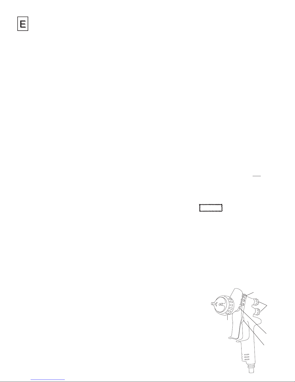
Daily, apply a drop of spray gun lubricant at trigger stud (39) and the
stem of air valve (32) where it enters air valve assembly. The shank
of uid needle (15) where it enters packing nut (28) should also be
oiled. Fluid needle packing (26) should be lubricated periodically.
Make sure air separator (9) and air cap retaining ring (1) threads are
clean and free of foreign matter. Before assembling air cap retaining
ring to air separator, clean the threads thoroughly, then add two
drops of spray gun lubricant to threads. Fluid needle spring (16) and
air valve spring (33) should be coated with a
very light grease, making sure that
any excess grease will not clog the
air passages.
Points of Lubrication
A. Trigger Points
B. Packing
C. Adjusting Knobs
D. Air Cap Retaining Ring Threads
E. Air Valve Cartridge
D
A
C
B
E
6
Page 7
TB-1016-A
Parts Replacement/
Maintenance
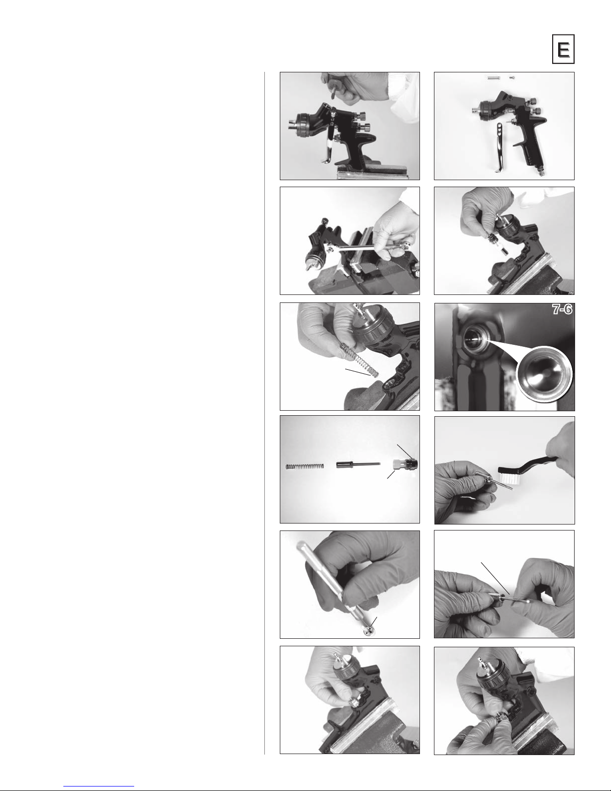
AIR VALVE INSTRUCTIONS
Servicing Air Valve
Reasons to service air valve:
A) Air valve not functioning properly
(may need cleaning).
B) Routine maintenance.
1. Remove trigger using a Star (T20) driver. (See
pictures 7-1 & 7-2)
2. Unscrew air valve using 14 mm wrench.
(See picture 7-3)
3. Remove air valve by gripping stem.
(See picture 7-4)
4. Remove spring with spring pad.
(See picture 7-5)
5. DO NOT REMOVE REAR SEAL FROM GUN
BODY. (See picture 7-6)
6. DO NOT REMOVE PLASTIC CAGE FROM
AIR VALVE BODY AS THIS MAY DAMAGE
THE CAGE. (See picture 7-7)
7. CLEAN
a. Remove all paint build up.
(See picture 7-8)
b. The 4 poppet holes must be clear.
(See picture 7-9)
c. Stem must be free to oat in poppet.
(See picture 7-10)
d. Stem must slide through cage bore
with slight resistance (due to seal).
e. Rear seal must look clean and in
position in the bore. (See picture 7-6)
f. If any of the above cannot be rectied,
replace the air valve (See Replacing
Air Valve).
8. Replace spring ensuring the end with
the plastic bearing pad goes in rst.
(See picture 7-5)
9. Insert air valve assembly into gun and carefully
feed through the rear seal
and over the spring. (See picture 7-11)
10. Tighten air valve assembly using ngers
rst, then wrench tighten with 14 mm wrench.
(See pictures 7-12 & 7-3)
11. Replace trigger. (See pictures 7-2 & 7-1)
12. If there is an air leak through the gun,
the air valve may need replacing (See Replacing
Air Valve).
SPRING PAD GOES
IN FIRST
AIR VALVE BODY
PLASTIC CAGE
ALL POPPET
HOLES MUST
BE CLEAR
7-1 7-2
7-3
7-5
REAR SEAL IN
GUN BODY
7-7
7-9
7-11
WIGGLE TO BE SURE
THAT STEM FLOATS
IN POPPET
7-10
7-12
7-4
7-6
7-8
7
Page 8
TB-1016-A
SPRING PAD
GOES IN FIRST
8-1 8-2
8-3 8-4
8-5 8-6
8-7 8-8
GROOVES IN SEAL FIT INTO
SERVICE TOOL
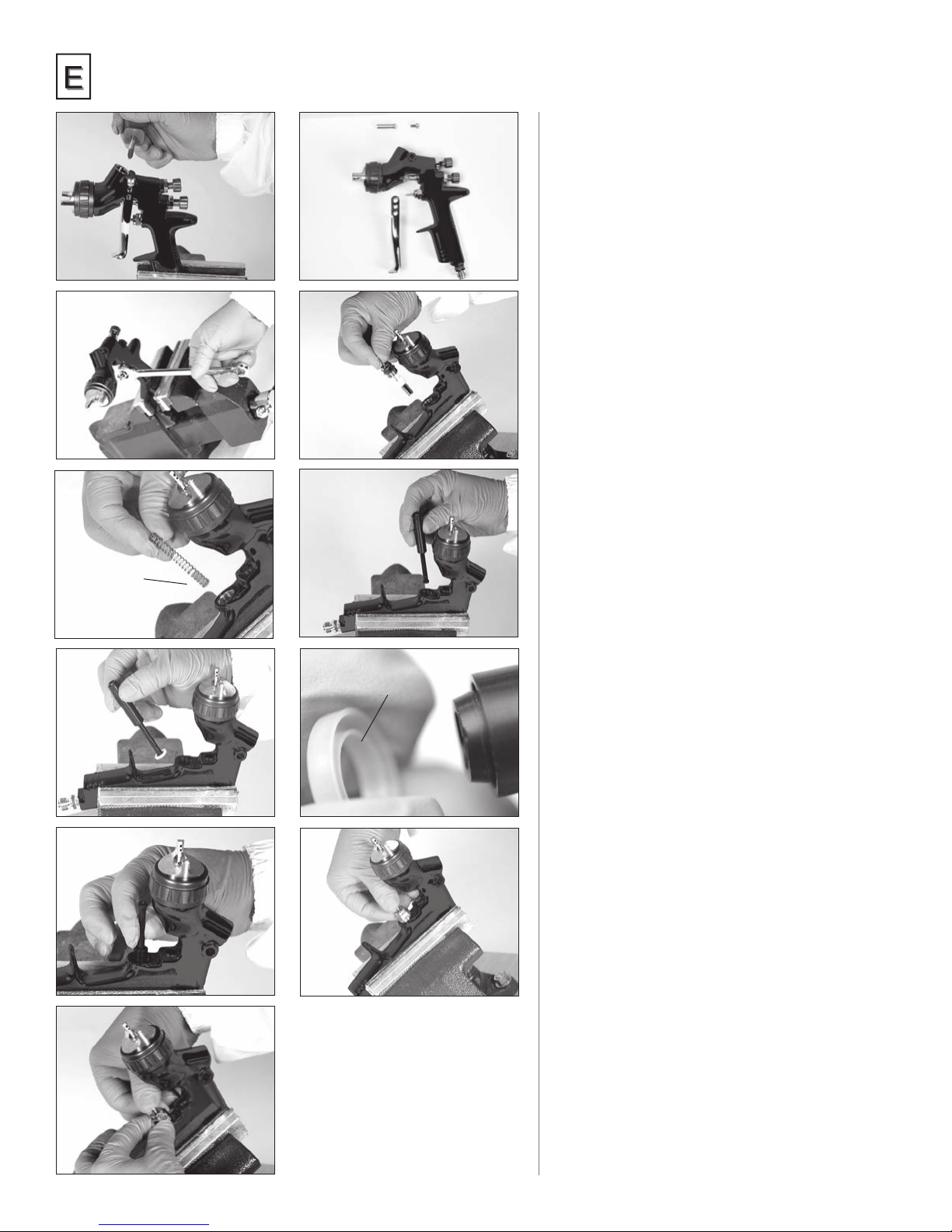
Replacing Air Valve
Reasons to replace air valve:
A) Air leak through the gun.
B) Air valve not operating properly.
1. Remove trigger using a Star (T20) driver. (See
pictures 8-1 & 8-2)
2. Unscrew air valve using 14 mm wrench.
(See picture 8-3)
3. Remove air valve by gripping the stem.
(See picture 8-4)
4. Remove spring with spring pad.
(See picture 8-5)
5. Hook out rear seal using service tool.
(See pictures 8-6 & 8-7)
6. Clean air valve bores in gun body with
a soft brush.
7. Place new rear seal onto service tool; grooves
must t in service tool form.
(See picture 8-8)
8. Push rear seal rmly into hole up
to shoulder, using service tool.
(See picture 8-9)
9. Insert new spring, ensuring the end
with the plastic bearing pad goes in rst.
(See picture 8-5)
10. Insert air valve assembly into gun and carefully
feed through the rear seal and over the spring.
(See picture 8-10)
11. Tighten air valve assembly using ngers rst,
then wrench tighten with 14 mm wrench.
(See pictures 8-11 & 8-3)
12. Replace trigger. (See pictures 8-2 & 8-1)
8-9 8-10
8-11
8
Page 9
TB-1016-A
Parts Replacement/
Maintenance
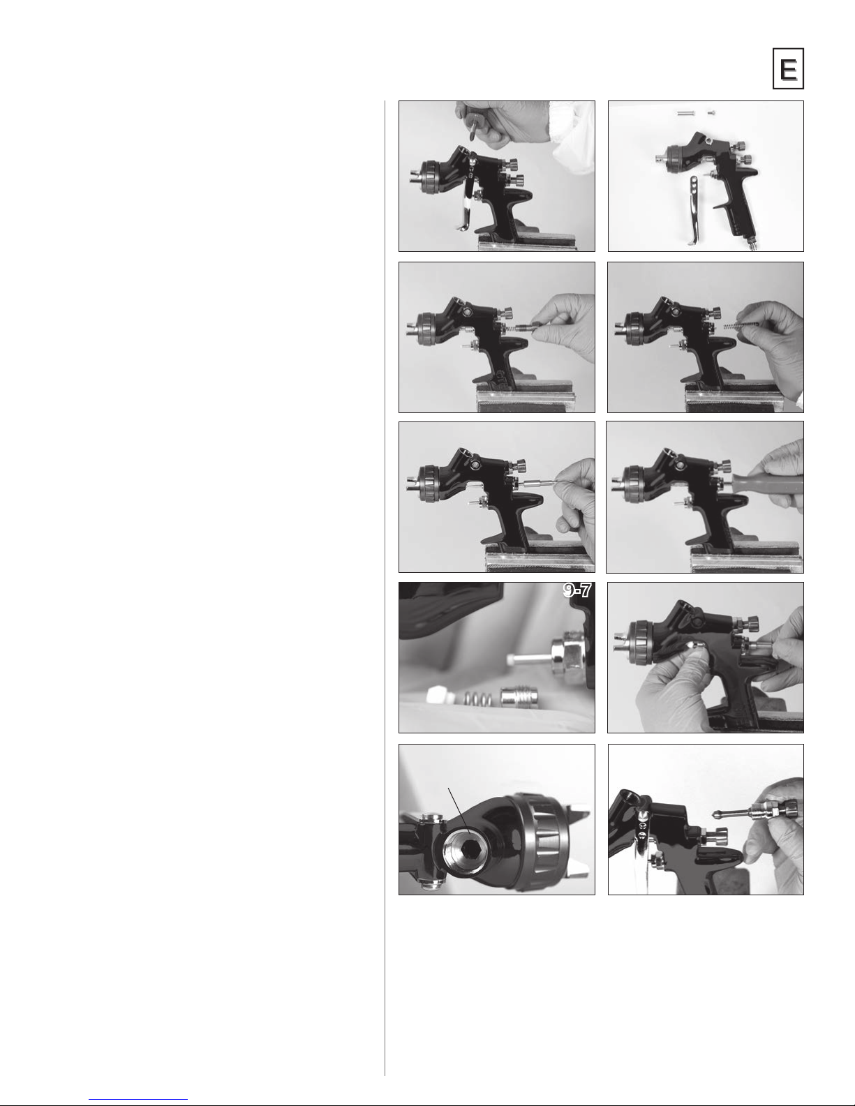
NEEDLE PACKING
REPLACEMENT INSTRUCTIONS
1. Remove trigger using a Star (T20) driver.
(See pictures 9-1 & 9-2)
2. Remove uid adjusting knob and needle
spring with spring pad from gun.
(See pictures 9-3 & 9-4)
3. Remove uid needle from gun body.
(See picture 9-5)
4. Loosen and remove packing nut using a straight
blade screwdriver. (See picture 9-6)
5. Discard old packing and packing spring if replacing.
Clean packing if reusing. Also clean packing spring
and nut. (See picture 9-7)
6. Partially insert clean uid needle into gun
and place packing nut, spring, and new packing
onto needle. Be sure tapered end of packing
goes into gun rst. (See pictures 9-7 & 9-8)
7. Insert uid needle all the way into gun body
seating in uid nozzle.
8. Tighten needle packing nut by hand, then
remove uid needle.
9. Tighten needle packing nut fully, using a straight
blade screwdriver. Don’t over tighten.
(See picture 9-6)
10. Reinstall uid needle, needle spring, spring
pad, and uid adjusting knob. (See pictures 9-5, 9-4
& 9-3) A drop or two of lubricant on parts assures
smooth operation.
11. Reinstall trigger. (See pictures 9-2 & 9-1)
A drop of lubricant assures smooth operation.
12. Trigger gun fully and screw in uid adjusting
knob until it stops. Back it off 1/2 turn and gun will
have full needle travel.
13. Trigger gun several times to verify
proper operation.
DON'T REMOVE FLUID INSERT
AND SEAL IN GUN BODY
9-1 9-2
9-3 9-4
9-5 9-6
9-7 9-8
9-9 9-10
FLUID INSERT REPLACEMENT/
MAINTENANCE
The uid insert and seal are NOT replaceable.
Don’t remove these parts. (See picture 9-9)
No maintenance is required for these parts other
than cleaning the internal bore.
SPREADER VALVE ASSEMBLY
REPLACEMENT/MAINTENANCE
The spreader valve assembly can be replaced if
damaged (See picture 9-10). Remove using a
14 mm wrench. The internal seal can be replaced
and is included in the TEKNA Gun Rebuild Kit.
9
Page 10
TB-1016-A
10-1 10-2
10-3 10-4
10-5 10-6
10-7 10-8
10-9 10-10
Parts Replacement/
Maintenance
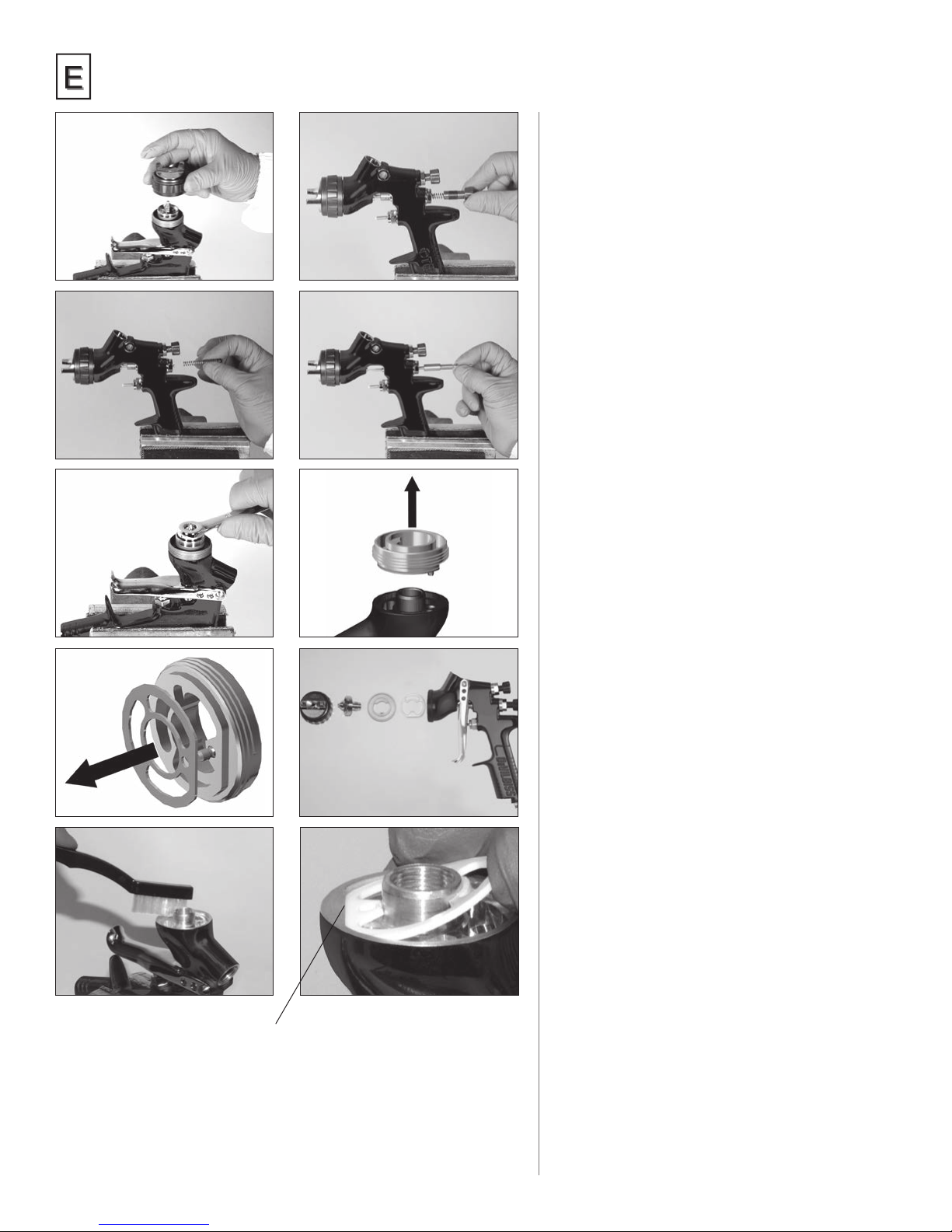
AIR SEPARATOR SEAL
REPLACEMENT
1. Remove air cap and retaining ring.
(See picture 10-1)
2. Remove uid adjusting knob, spring, and
spring pad. (See pictures 10-2 & 10-3)
3. Remove uid needle from gun body.
(See picture 10-4)
4. Remove uid nozzle (using 10 mm wrench),
air separator, and seal.
(See pictures 10-5 & 10-6)
5. Remove seal from air separator.
(See picture 10-7)
6. Clean front of gun if required, using
a soft brush, as well as the air separator,
uid nozzle, air cap, and retaining ring.
(See pictures 10-8 & 10-9)
7. Place a new air separator seal onto the front of the
gun. The at on the seal must align with the gun’s
at. (See picture 10-10)
8. Reinstall the air separator, making sure the pin is
engaged into the hole in the gun body. Reinstall the
uid nozzle and torque the uid nozzle to 18–20
nm (13–15 ft-lbs). Don’t over torque the uid
nozzle. A drop or two of lubricant on the uid nozzle
threads and air separator threads insures smooth
assembly. Reinstall the air cap and retaining ring.
9. Insert uid needle all the way into the gun
body, seating in uid nozzle.
(See picture 10-4)
10. Reassemble needle spring, spring pad,
and uid adjusting knob. A drop or two
of lubricant assures smooth operation.
(See pictures 10-2 & 10-3)
11. Trigger gun fully and screw in uid adjusting
knob until it stops. Back it off 1/2 turn and
gun will have full needle travel.
12. Trigger gun several times to verify
proper operation.
Flats on seal and gun must align.
10
Page 11

Parts Replacement/Maintenance
Chart 1 – Air Caps
ORDER NO. FOR
AIR CAP
702723 (HVLP) Basecoats – Solvent &
702724 (HVLP) Clears, Single Stages,
703062 (High
Efciency)
NOTE 1: Guns with HVLP caps must not exceed 0.7 bar (10 psi) air cap pressure with
gun fully triggered. (Aproximately 26 psi gun inlet pressure.) (See accessories
for air cap test kits which are available to set the exact cap pressure.)
Compliance with SCAQMD and other air regulatory agencies requires gun inlet
pressure not to exceed 1.5 bar (22 psi) with gun fully triggered when the high
efciency cap is used. Gun inlet pressure may be adjusted as required to any
desired value in areas not requiring EPA compliance.
APPLICATION NUMBER
Waterborne
Waterborne Basecoats
Basecoats – Solvent &
Waterborne, Clears,
Single Stages
ON CAP
202 1.2-1.5 bar
909 1.5-1.8 bar
7E7 1.1-1.5 bar
RECOMMENDED
INLET PRESSURE
BAR/PSI
18-22 psi
22-26 psi
16-22 psi
AIR FLOW
LPM/SCFM
382-434 LPM
13.5-15.5 SCFM
396-453 LPM
14-16 SCFM
255-312 LPM
9-11 SCFM
RECOMMENDED FLUID
TIP (MM)
1.2, 1.3, 1.4 –
Also 1.5 for waterborne only
1.2, 1.3, 1.4 –
Also 1.5 for waterborne only
1.2, 1.3, 1.4 –
Also 1.5 for waterborne only
TB-1016-A
NOTE 2: When removing air cap from retaining ring, don’t remove slip ring (2)
or retaining ring seal (5) from retaining ring. Damage to the parts may
occur. Slip ring and retaining ring seal are not available as replacements.
Simply wipe parts clean and reassemble with new or clean air cap.
Chart 2 – Fluid Nozzle & Fluid Needles
NO. ON
FLUID NOZZLE
SN-37-11 1.1 SN-38-11 702711
SN-37-12 1.2 SN-38-12 702712
SN-37-13 1.3 SN-38-13 702713
SN-37-14 1.4 SN-38-14 702714
SN-37-15 1.5 SN-38-15 702715
NOTE: When replacing the uid nozzle or uid needle, replace both at the same time.
Lightly lubricate the threads of the uid nozzle before reassembling. Torque
to 18–20 nm (13–15 ft-lbs). Don’t over tighten the uid nozzle. Use 10 mm
wrench supplied with gun.
TIP SIZE I.D.
(MM)
NO. ON FLUID NEEDLE
(TO MATCH FLUID NOZZLE)
ORDER NO. FOR
NOZZLE & NEEDLE SET
11
Page 12
TB-1016-A
12
14
13
15
16
11
19
17
18
20
21
22
25
23
24
6
1
2 3 4 5
8
7
Fluid Nozzle
Torque to 18–20 nm (13–15 ft-lbs)
7
30
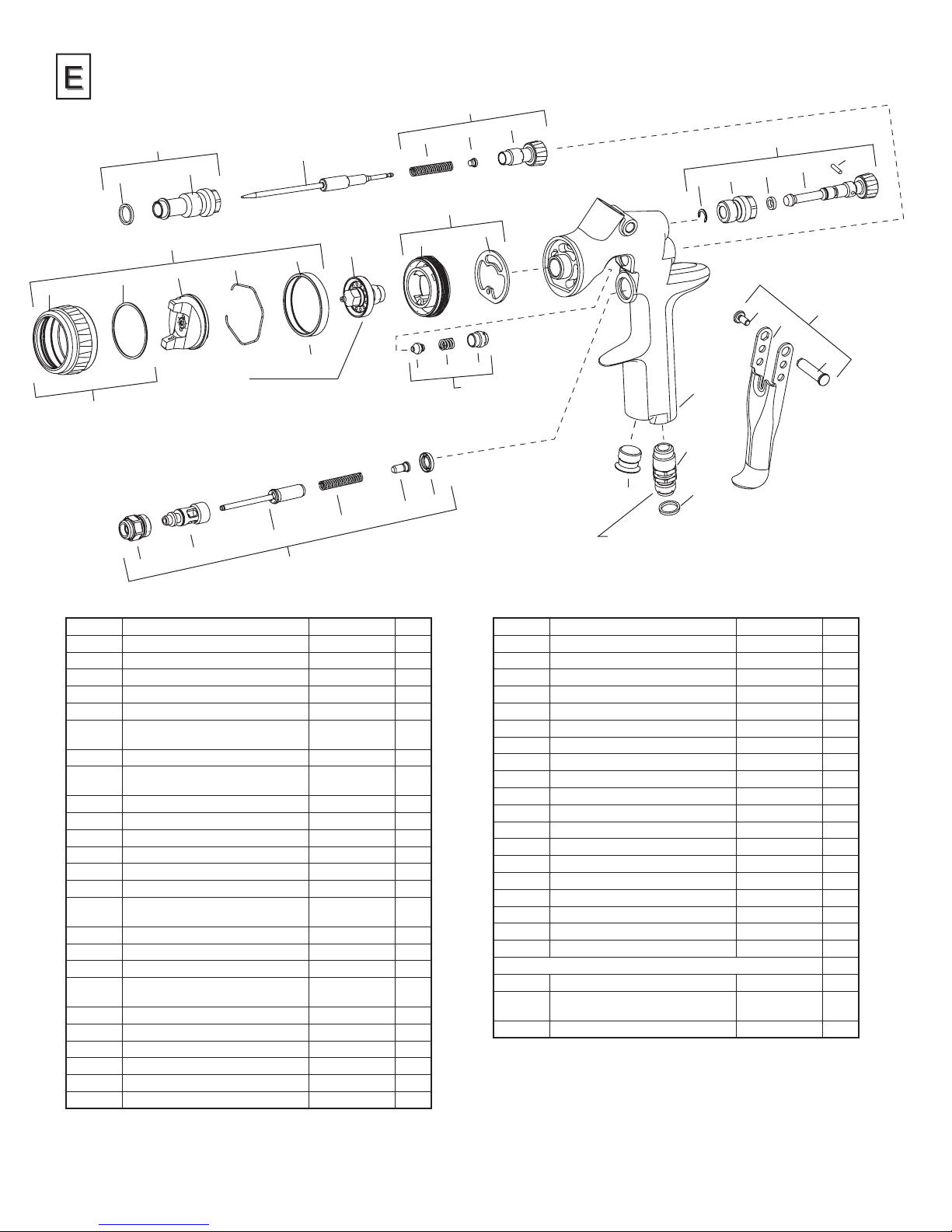
REF. NO. DESCRIPTION PART NO. QTY
1 Air Cap Retaining Ring 1
2 Slip Ring 1
3 Air Cap 1
4 Air Cap Retaining Clip 191972 1
5 Retaining Ring Seal 1
6 Air Cap & Ring See Chart 1,
7 Air Cap Retaining Ring & Seals 702725 1
8 Fluid Nozzle See Chart 2,
9 Air Separator 1
*10 Air Separator Seal (kit of 2) 702726 1
11 Air Separator & Seal Kit 702727 1
*12 Body Bushing Gasket 1
13 Body Bushing 1
14 Body Bushing & Gasket 702728 1
15 Fluid Needle See Chart 2,
*16 Needle Spring 1
*17 Needle Spring Pad 1
18 Fluid Adjusting Knob 1
19 Fluid Adjusting Knob, Spring,
& Pad Kit
*20 Retaining Clip 1
21 Spreader Valve Body 1
*22 O-ring 1
23 Spreader Valve Adjusting Knob 1
*24 Spreader Valve Pin 1
25 Spreader Valve Assembly 702730 1
31 32 33 34 35
36
p.11
p.11
p.11
702729 1
9 10
26 27 28
1
1
1
37
29
44
42
41
43
Air Inlet – Torque to 20 nm (15 ft-lbs)
Use medium strength thread sealant
(i.e. Devcon #2242 blue, or equivalent)
on threads
REF. NO. DESCRIPTION PART NO. QTY
*26 Needle Packing 1
*27 Packing Spring 1
*28 Packing Nut 1
29 Packing, Spring & Packing Nut Kit 702731 1
30 Air Valve Body 1
31 Air Valve Cage 1
32 Air Valve Poppet 1
33 Air Valve Spring 1
34 Air Valve Spring Pad 1
35 Air Valve Seal (Kit of 5) 803307 1
36 Air Valve Assembly 702732 1
*37 Trigger Stud Screw (T20 Star) 1
38 Trigger 1
*39 Trigger Stud 1
40 Trigger, Stud & Screw Kit 702733 1
41 Plug 1
42 Air Inlet 702734 1
43 Colour ID Ring Kit (4 Colours) 702735 1
44 Gun Body 1
OTHER SALABLE PARTS / ACCESSORIES
Wrench (10 & 14mm) 702740
Seal and Pin Kit (Kit of 5)
(Items 20, 22 and 24.)
Air Adjusting Valve 702737
192229
* The TEKNA Spray Gun Repair Kit (702736) contains all the parts
indicated with an asterisk.
38
40
39
12
Page 13
Troubleshooting Possible Problems
in Operation
TB-1016-A
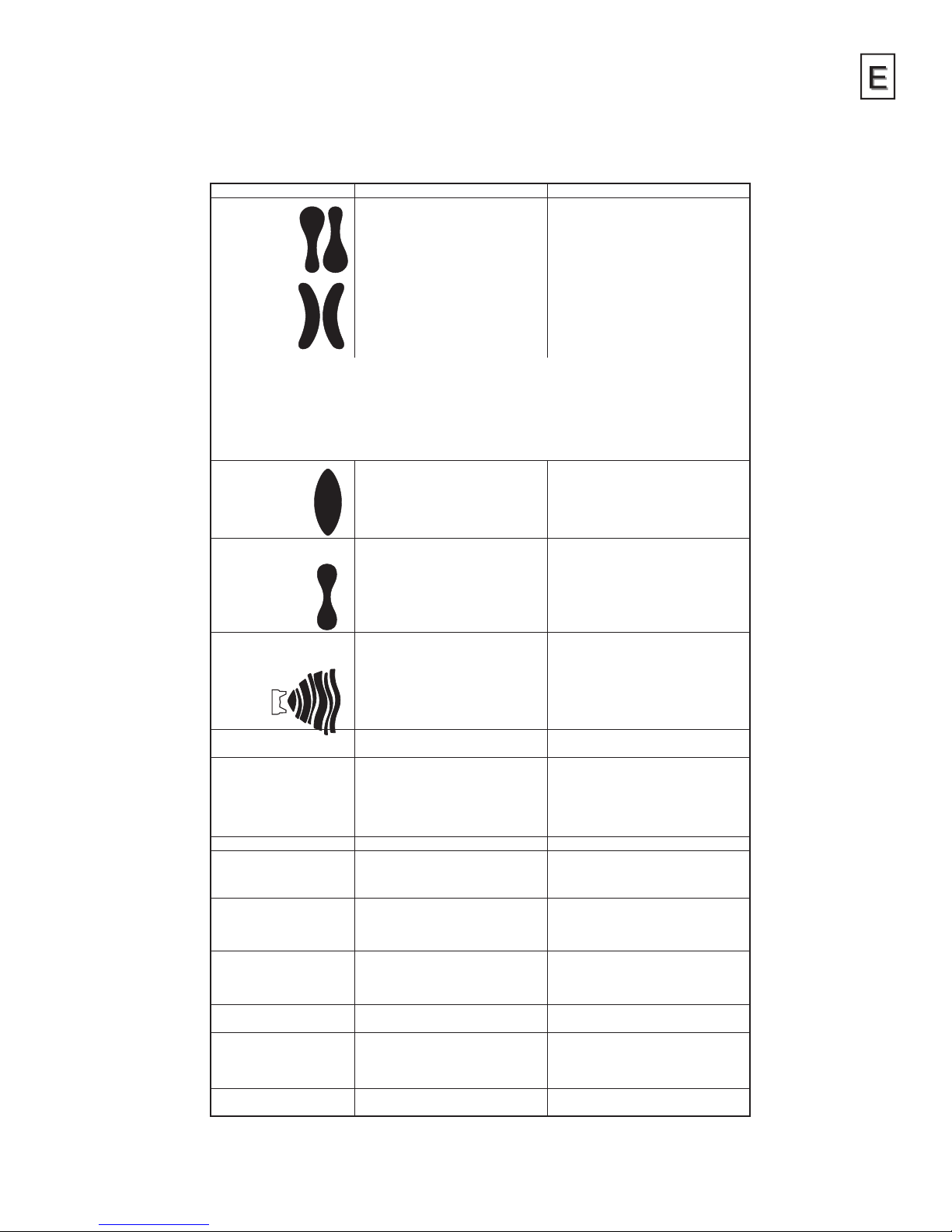
CONDITION CAUSE CORRECTION
Heavy top or
bottom pattern
Heavy right
or left side
pattern
Remedies for the top-heavy, bottom-heavy, right-heavy, and left-heavy patterns:
1. Determine if the obstruction is on the air cap or the uid nozzle. Do this by making a test spray pattern. Then,
rotate the cap one-half turn and spray another pattern. If the defect is inverted, obstruction is on the air cap.
Clean the air cap as previously instructed. Also check for dried paint just inside the cap center hole opening;
remove by washing with solvent.
2. If the defect is not inverted, it is on the uid nozzle. Clean nozzle. Check for a ne burr on the edge of the uid
nozzle. Remove with #600 wet or dry sandpaper.
Heavy centre
pattern
Split spray pattern
Jerky or fluttering spray
Unable to get round spray
Will not spray
Paint bubbles in cup
Fluid leaking or dripping
from cup lid
Starved spray pattern
Excessive overspray
Excessive fog
Dry spray
Fluid leaking from
packing nut
Horn holes plugged. Clean. Ream with non-metallic point.
Obstruction on top or bottom
of uid nozzle.
Cap and/or nozzle seat dirty. Clean
Left or right side horn holes plugged. Clean. Ream with non-metallic point.
Dirt on left or right side of
uid nozzle.
Spreader adjustment valve set
too low.
Atomising pressure too low. Increase pressure.
Material too thick. Thin to proper consistency.
Atomisation air pressure too high. Reduce at regulator or gun handle.
Fluid adjusting knob turned in
too far.
Spreader adjusting valve set too high. Turn in clockwise to achieve proper
*Loose or damaged uid nozzle/seat. Tighten or replace.
Loose or broken cup uid nipple. Tighten or replace cup.
Material level too low. Rell.
Container tipped too far. Hold more upright.
Obstruction in uid passage. Back ush with solvent.
Loose uid needle packing nut. Tighten.
Damaged uid needle packing. Replace.
Spreader valve not seating properly. Clean or replace.
Air cap retaining ring loose. Tighten.
No air pressure at gun. Check air supply and air lines, blow out
Fluid adjusting knob not
open enough.
Fluid too heavy for gravity feed. Thin material and/or change to larger
Fluid nozzle not tight. Tighten to 18–20 nm (13-15 ft-lbs).
Cup lid loose. Push in or replace.
Dirty cup or lid. Clean.
Cracked cup or lid. Replace cup and lid.
Inadequate material ow. Back uid adjusting knob out or change
Low atomisation air pressure. Increase air pressure and
Too much atomisation air pressure. Reduce pressure.
Gun too far from work surface. Adjust to proper distance.
Improper stroking (arcing, gun motion
too fast).
Too much or too-fast-drying thinner. Remix properly.
Too much atomisation air pressure. Reduce pressure.
Air pressure too high. Reduce air pressure.
Gun too far from work surface. Adjust to proper distance.
Gun motion too fast. Slow down.
Gun out of adjustment. Adjust.
Packing nut loose. Tighten.
Packing worn. Replace.
Clean.
Clean.
Turn out counter clockwise to achieve
proper pattern.
Turn out counter clockwise to achieve
proper pattern.
pattern.
gun air passages.
Turn out counter clockwise.
uid nozzle size.
to larger uid nozzle size.
rebalance gun.
Move at moderate pace, parallel to work
surface.
*Most common problem.
13
Page 14
TB-1016-A
Troubleshooting Possible Problems in Operation (cont'd)
CONDITION CAUSE CORRECTION
Fluid leaking or dripping
from front of gun
Fluid dripping or leaking
from bottom of cup
Runs and sags
Thin, sandy coarse finish
drying before it flows out
Thick, dimpled finish
“orange peel”
Fluid nozzle or uid needle worn
or damaged.
Foreign matter in uid nozzle.
Fluid needle spring broken.
Wrong size uid needle or
uid nozzle.
Cup loose on gun. Tighten
Cup threads dirty. Clean.
Too much material ow. Turn uid adjusting knob clockwise
Material too thin. Mix properly or apply light coats.
Gun tilted on an angle, or gun motion
too slow.
Gun too far from surface. Check distance. Normally approx.
Too much air pressure. Reduce air pressure and check
Improper thinner being used. Follow paint manufacturer’s mixing
Gun too close to surface. Check distance. Normally approx.
Air pressure too low. Increase air pressure or reduce
Improper thinner being used. Follow paint manufacturer’s mixing
Material not properly mixed. Follow paint manufacturer’s mixing
Surface rough, oily, dirty. Properly clean and prepare.
Replace uid nozzle and uid needle.
Clean.
Replace.
Replace uid nozzle and uid needle.
or switch to smaller uid nozzle and
uid needle size.
Hold gun at right angle to work and adapt
to proper gun technique.
150–200 mm (6–8").
spray pattern.
instructions.
150–200 mm (6–8"). Too much material
coarsely atomised.
uid ow.
instructions.
instructions.
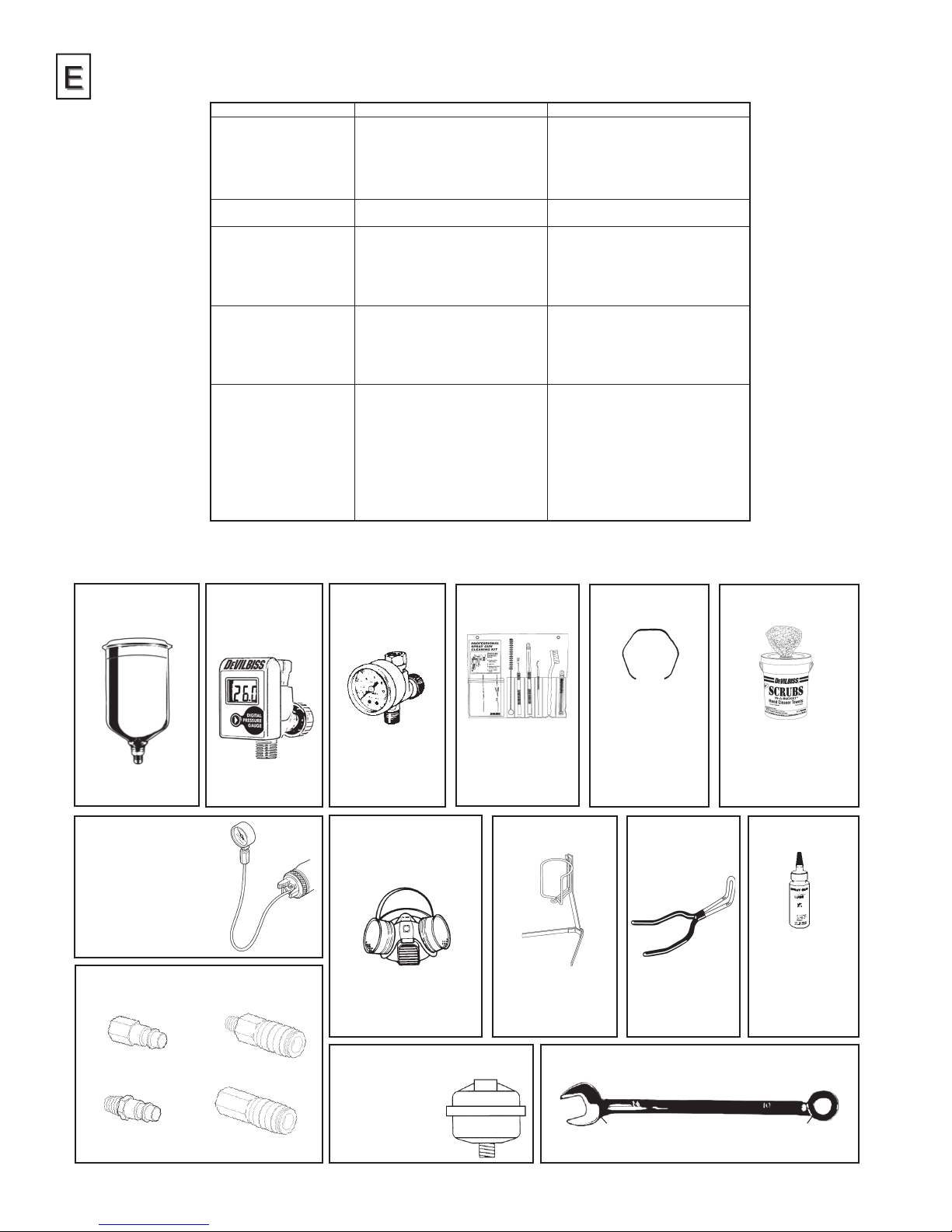
Accessories
702576
TEKNA 900cc
Aluminum Cup
Easy to use and clean
design.
702738 HVLP #202
702739 HVLP #909
Air Cap Test Kit
The purpose of this test
kit is to measure air cap
atomizing air pressure at
the center air port of the air
cap. Used to confirm code
compliance and as a daily
quality control measure.
Automotive Refinish Quick Connects
For HVLP Guns (Air)
High Flow Type.
HAV-555
DeVilbiss
Air Adjusting Valve
with Gauge
Use to precisely set
air pressure to gun.
HAV-512
Adjusting Valve
Use to control air
usage at gun.
40-128
Twin Cartridge,
Paint Spray
Respirator
NIOSH-Certified
(TC84A-1623) for respiratory protection in atmospheres not immediately
dangerous to life.
192212 Professional
Spray Gun
Cleaning Kit
Contains six precision tools designed
to effectively clean
all DeVilbiss, Binks,
Finishline and other
brand spray guns.
GH-505 Gun
Holder
Gun holders are
made to hold standard paint cups, gravity feed guns and
cups, and paint filters.
JGA-156-K10
191972
Spring Clips
Joins any single
piece DeVilbiss
air cap with latest
version MBC-368,
MSA-1 or GTI3 retaining rings.
Helps prevent parts
loss and provides
easier assembly.
192219
Gun Holder
Gun holder made
to hold guns with
gravity cups.
192218 Scrubs®
Hand Cleaner Towels
®
Scrubs
moistened hand cleaner
towel for painters, body
men and mechanics that
go where you go and no
water is needed.
are a pre-
Spray Gun Lube
SSL-10 (2 oz. bottle)
Compatible with
all paint materials; contains no
silicone or petroleum distillates to
contaminate paint.
MSDS Sheet available upon request.
HC-4419 Stem
1/4" NPT(F)
HC-1166 Stem
1/4" NPT(M)
HC-4719 Coupler
1/4" NPT(M) /NPS(M)
HC-4720 Coupler
1/4" NPT(F)
14
HAF-507 Whirlwind™
In-Line Air Filter
Removes water, oil,
and debris from the
air line.
702740 TEKNA Wrench
14 mm 10 mm
For maintenance use.
Page 15

WARRANTY
This product is covered by DeVilbiss' 2 Year Limited Warranty.
DeVilbiss Sales and Service: www.devilbiss.com
DeVilbiss Automotive Refinishing
DeVilbiss has authorized distributors throughout the world.
For equipment, parts and service, check the Yellow Pages
under “Automotive Body Shop Equipment and Supplies.”
For technical assistance, see listing below.
U.S.A./ Canada Customer Service Office:
11360 S. Airfield Road, Swanton, OH 43558
Toll-Free Telephone: 1-800-445-3988 (U.S.A. and Canada only)
Toll-Free Fax: 1-800-445-6643
This product is manufactured in the UK by:
Finishing Brands UK, Ltd.
Ringwood Road,
Bournemouth,
BH11 9LH, UK
Distributed exclusively in North America by:
DeVilbiss Automotive Renishing
Swanton, OH 43558
TB-1016-A
8/14 © 2014 DeVilbiss Automotive Refinishing. All rights reserved. Printed in U.S.A.
15
Page 16

TB-1016-A
© 2014 DeVilbiss Automotive Renishing. All rights reserved. 8/14
 Loading...