

Page 1
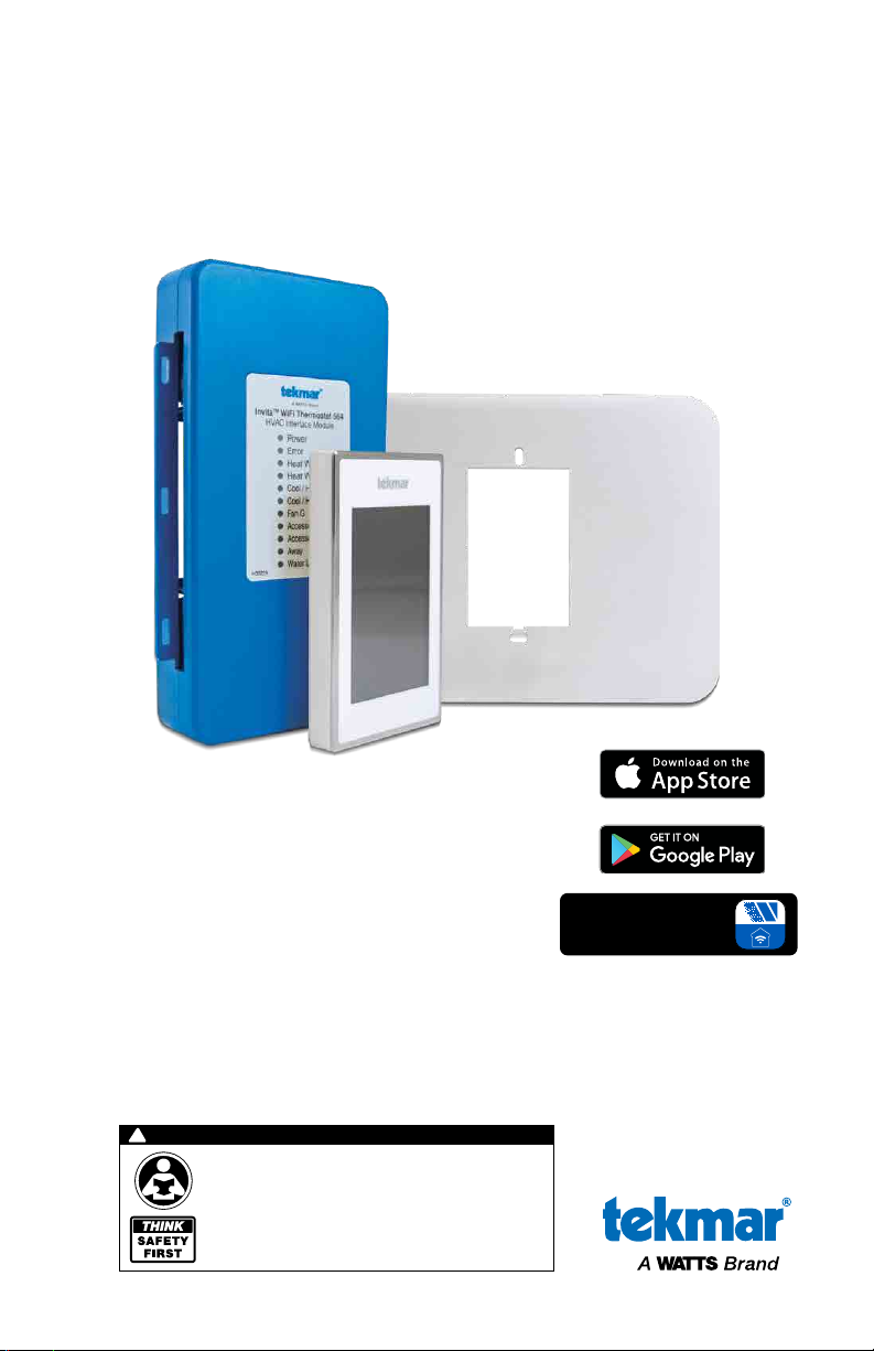
Installation Manual
IOM-T-564
Installation, Operation and Maintenance
Invita® WiFi Thermostat
Wall Plate
HVAC
Interface Module
Invita®
WiFi Thermostat
Compatible With
• Conventional systems:
2-stage heating, 2-stage cooling, fan and 2 accessories
• Heat pump systems:
4-stage heating, 2-stage cooling, fan,reversing valve
and 1 accessory
• Supports dual fuel systems
• Accessory options:
Humidifier, dehumidifier, HRV/ERV ventilator, heat pump loop valve
!
WARNING
Please read carefully before proceeding with
installation. Your failure to follow any attached
instructions or operating parameters may lead to the
product’s failure.
Keep this Manual for future reference.
Works with the
®
Watts
Home Mobile App
Page 2

Table of Contents
Important Safety Information ......................................................3
Installation .....................................................................4
Preparation ..................................................................4
Equipment Connections ..........................................................6
Wiring the HVAC Interface Module...................................................7
1-Stage Heat and 1-Stage Cooling with Fan .........................................7
Up to 2-Stage Furnace and 2-Stage Air Conditioner ...................................8
Up to 2-Stage Hydronic Boiler and 2-Stage Air Conditioner .............................8
Up to 2-Stage Heat Pump with Auxiliary Heat ........................................9
Up to 2-Stage Heat Pump with 2-Stage Dual Fuel ....................................9
Dehumidification using a DX Coil.................................................10
Humidifier ..................................................................10
HRV/ERV Ventilator...........................................................10
Outdoor Sensor .............................................................10
Room Sensor ...............................................................11
Watts® FloodSafe® Water Detector Shutoff . . . . . . . . . . . . . . . . . . . . . . . . . . . . . . . . . . . . . . . . .11
Startup ......................................................................11
Home Screen .................................................................12
Symbols .....................................................................12
User Settings..................................................................13
Away......................................................................13
Schedule ..................................................................13
Display ....................................................................14
Time ......................................................................15
Fan .......................................................................15
WiFi ......................................................................16
WiFi and Connectivity Troubleshooting ............................................17
Installer Settings ...............................................................18
Setup .....................................................................18
Setup - Toolbox .............................................................18
Setup - Temp ...............................................................19
Setup - Sensors .............................................................20
Setup - Alerts ...............................................................21
Setup - Relays ...........................................................22–24
Setup - Humidity.............................................................25
Setup - HRV / ERV Ventilation...................................................26
Sequence of Operation ..........................................................27
Heating and Cooling Operation ...............................................27-29
Relative Humidity Operation ....................................................30
HRV / ERV Ventilator Operation..................................................31
Heat Pump Loop Valve Operation................................................31
Error Messages .............................................................32–33
Technical Data .................................................................35
Limited Warranty . . . . . . . . . . . . . . . . . . . . . . . . . . . . . . . . . . . . . . . . . . . . . . . . . . . . . . . . . . . . . . .36
2
Page 3
Important Safety Information
It is your responsibility to ensure that this thermostat is safely installed according to all applicable
codes and standards. tekmar
or maintenance.
This symbol identifies hazards which, if not avoided,
could result in death or serious injury.
®
is not responsible for damages resulting from improper installation and/
This is a safety-alert symbol.
The safety alert symbol is
shown alone or used with
a signal word (DANGER,
WARNING, or CAUTION),
a pictorial and/or a safety
message to identify hazards.
When you see this symbol
alone or with a signal word
on your equipment or in
this manual, be alert to the
potential for death or serious
personal injury.
This pictorial alerts you to
electricity, electrocution, and
shock hazards.
• It is the installer’s responsibility to ensure
that this control is safely installed according
to all applicable codes and standards.
• Improper installation and operation of this
control could result in damage to the
equipment and possibly even personal
injury or death.
• This control is not intended for use as a
primary limit control. Other controls that are
intended and certified as safety limits must
be placed into the control circuit.
NOTICE
Do not attempt to service the thermostat.
There are no user serviceable parts inside the
thermostat. Attempting to do so voids the
warranty.
This symbol identifies hazards which, if not avoided,
could result in minor or moderate injury.
This symbol identifies practices, actions, or failure
to act which could result in property damage or
damage to the equipment.
Read manual and all product labels BEFORE using
the equipment. Do not use
unless you know the safe
and proper operation of this
equipment. Keep this manual available for easy access
by all users. Replacement
manuals are available at
tekmarControls.com
3
Page 4
Installation
Preparation
Tools Required
• tekmar or jeweler screwdriver
• Phillips head screwdriver
• Wire stripper
Materials Required
• 18 AWG LVT Solid Wire (low voltage connections)
Ensure power to connecting equipment is off. To prevent the risk of personal
injury and/or death, make sure power is not applied to the thermostat or HVAC
Interface Module until they are fully installed and ready for configuration. All work
must be done with power to the circuit being worked on turned off.
NOTICE
Please be aware local codes may require this thermostat to be installed or connected by
an electrician.
NOTICE
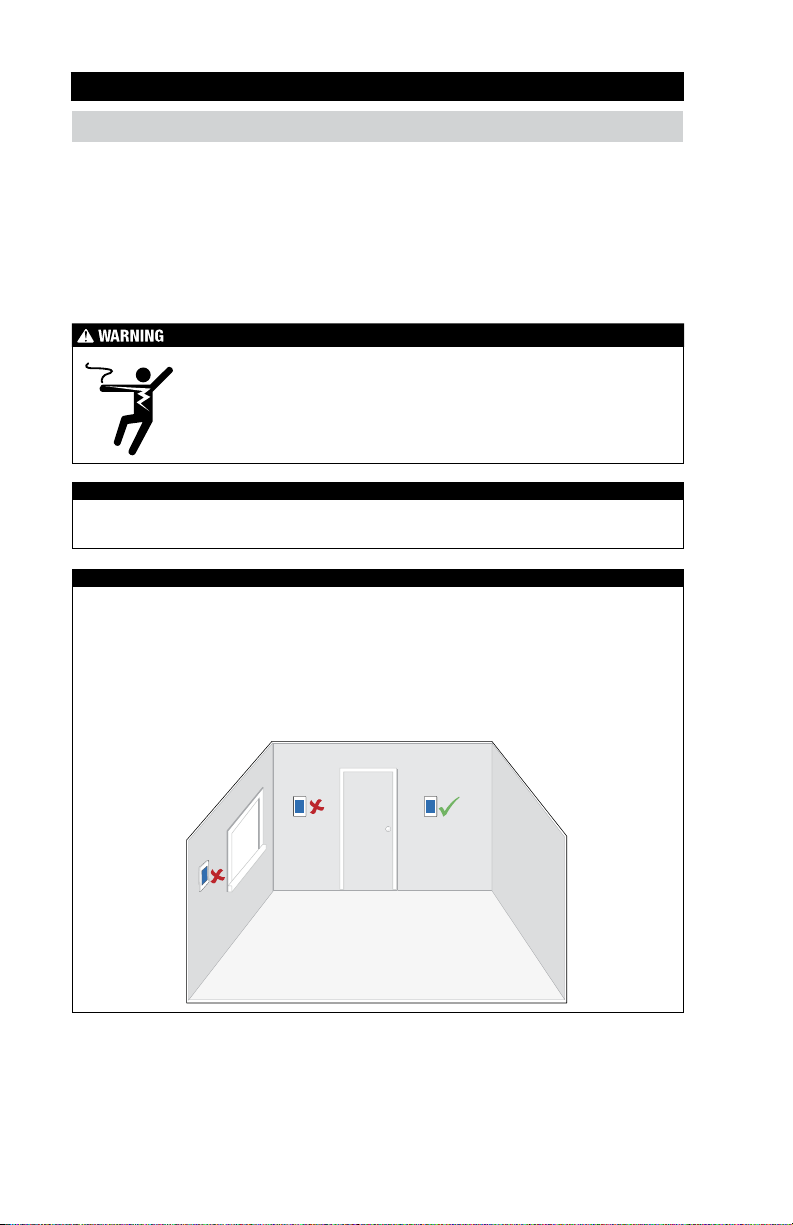
Thermostat Location
Consider the following:
• Interior wall. Keep dry. Avoid potential leakage onto the control.
• No draft, direct sun, or other cause for inaccurate temperature readings.
• Drill (for wall anchor)
3
•
⁄16" drill bit (for wall anchor)
• Away from equipment, appliances, or other
sources of electrical interference.
• Approximately 5 feet (1.5 m) off the finished
floor.
• The maximum length of wire is 500 feet (150 m).
1. Remove the old thermostat
If more than 2 wires are present, identify the R & C wires for use when connecting the Invita WiFi
Thermostat. Additional wires should be secured in a way that prevents them from touching the circuit
board or terminals on the Invita after the R & C wires are connected.
4
Page 5
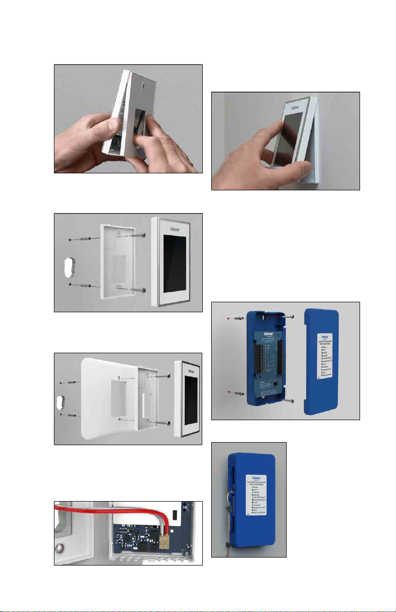
2. Mount Invita base to wall
Remove the back plate from the thermostat.
Secure the Invita thermostat back plate to a
2 x 4" electrical box with machine screws or to
drywall using wood screws with wall anchors.
If the wall has damage extending beyond the width
of the Invita WiFi Thermostat, place the wall plate
trim behind the back plate.
4. Attach the thermostat
to back plate
Align the 2 notches at the top of the base plate
with the holes on the top of the thermostat then
rotate on the hinge point down to close.
5. Mounting the HVAC
Interface Module
Locate the HVAC Interface Module so that it can
connect to the other end of the existing wire from
the thermostat. After removing the cover, secure
the HVAC Interface Module to the wall, the HVAC
equipment chassis or HVAC plenum using the
holes at the top and bottom of the module.
Wiring to the module enters from opening on
the sides or the back. Refer to the diagrams on
pages 6 to 11 for wiring details.
3. Wiring the Invita WiFi Thermostat
Connect the 2 wires from the old thermostat to the
terminals on the back of the Invita WiFi Thermostat.
This connection is not polarity sensitive.
6. Replace the Cover
Push the HVAC
Interface Module
Cover towards the
base. Top and bottom
clips hold the cover
in place.
5
Page 6
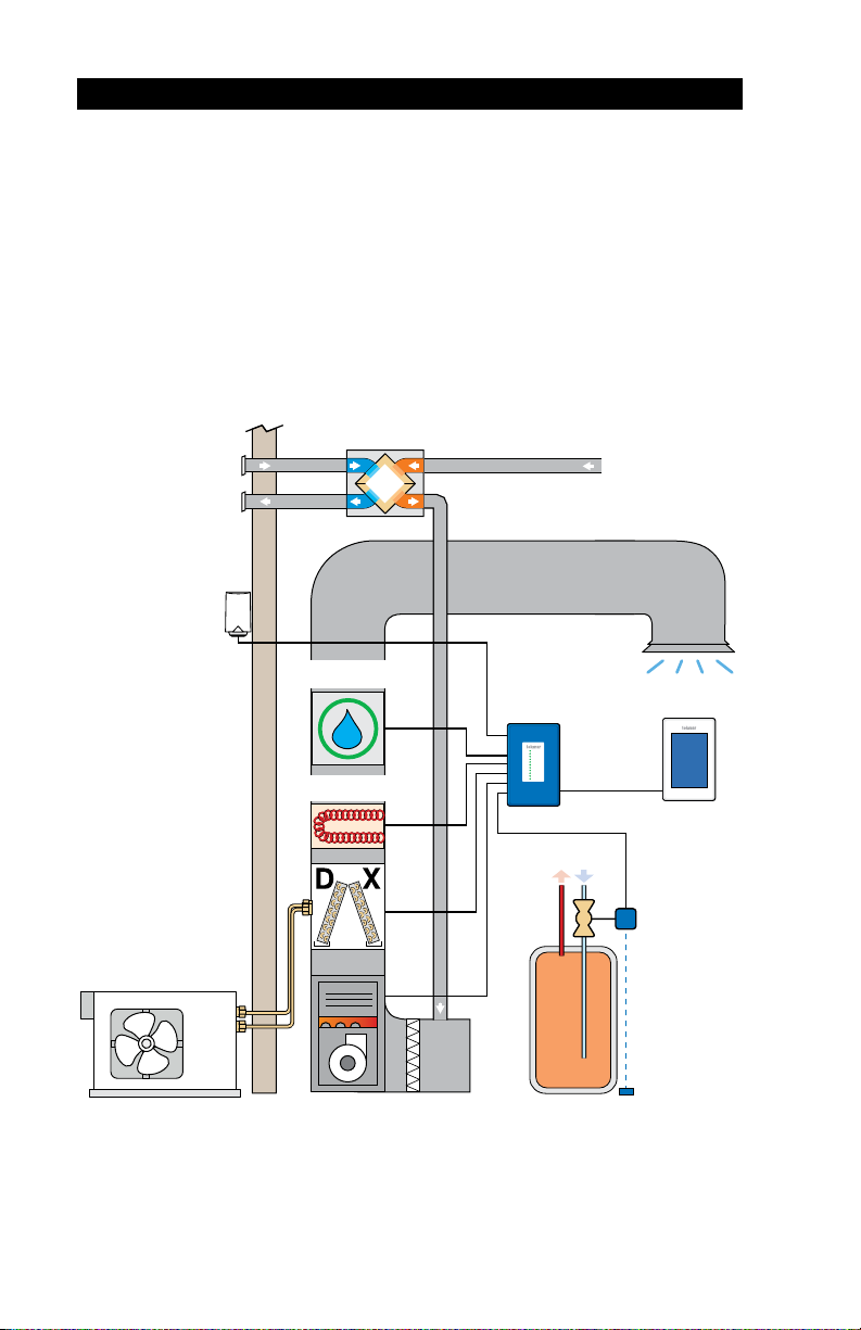
Equipment Connections
This illustration shows various equipment connected to the HVAC Interface Module. Other equipment
may be included in your application.
Conventional systems:
• Up to 2-stage heating, 2-stage cooling, fan and 2 accessories
Heat pump & dual fuel systems:
• Up to 4-stage heating, 2-stage cooling, fan, reversing valve and 1 accessory
Accessory options:
• Humidifier, dehumidifier, HRV/ERV ventilator
HRV/ERV
Ventilator
Optional
Outdoor
Sensor
6
Air Conditioner
or
Heat Pump
Humidifier
Electric Coil
Furnace
HVAC
Interface
Module
Hot Water Tank
Invita WiFi
Thermostat
Watts
W
FloodSafe
Water Detector
Shutoff
®
Page 7
Wiring the HVAC Interface Module
Ensure power to connecting equipment is off. To prevent the risk of personal
injury and/or death, make sure power is not applied to the thermostat or HVAC
Interface Module until they are fully installed and ready for configuration. All work
must be done with power to the circuit being worked on turned off.
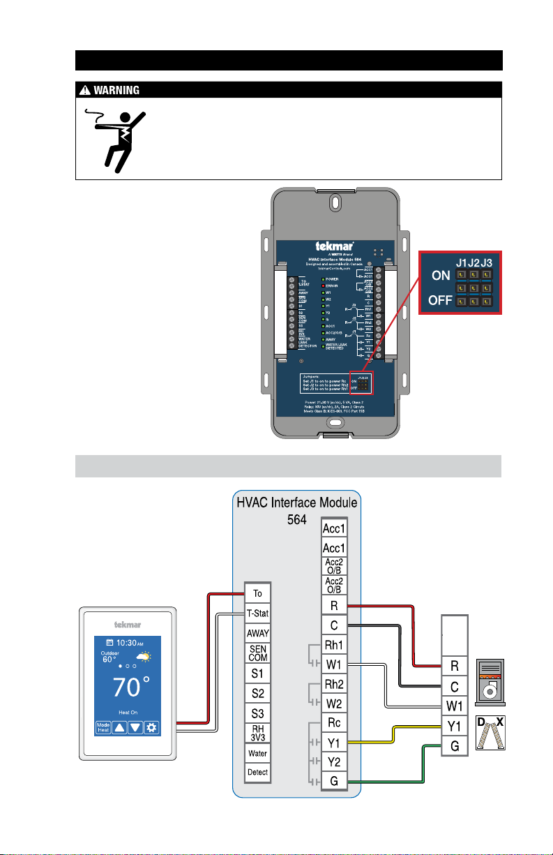
The HVAC Interface Module includes
three relay power jumper connectors.
These are used to provide power
between terminals when necessary.
• Set Jumper J1 to On to connect
power R to the Rc terminal.
• Set Jumper J2 to On to connect
power R to the Rh2 wiring terminal.
• Set Jumper J3 to On connects power
R to the Rh1 wiring terminal.
• Set the jumper to off to disconnect
the power from Rh1, Rh2, or Rc
respectively.
1-Stage Heat and 1-Stage Cooling with Fan
Jumpers:
J1 = On
J2 = Off
J3 = On
Essential Settings:
Heating Type = Conventional
Equipment = 1 Heat/1 Cool
Radiant Floor Heating = No
7
Page 8
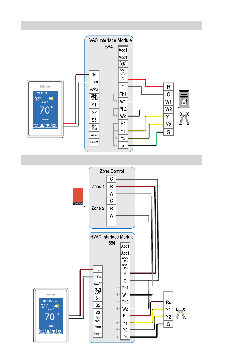
Up to 2-Stage Furnace and 2-Stage Air Conditioner
Essential Settings:
Heating Type = Conventional
Equipment = 2 Heat/2 Cool
Radiant Floor Heating = No
Jumpers:
J1 = On
J2 = On
J3 = On
Furnace
Air
Conditioner
Up to 2-Stage Hydronic Boiler and 2-Stage Air Conditioner
Essential Settings:
Heating Type = Conventional
Equipment = 2 Heat/2 Cool
Radiant Floor Heating = Yes
Jumpers:
J1 = Off
J2 = On
J3 = On
8
Page 9
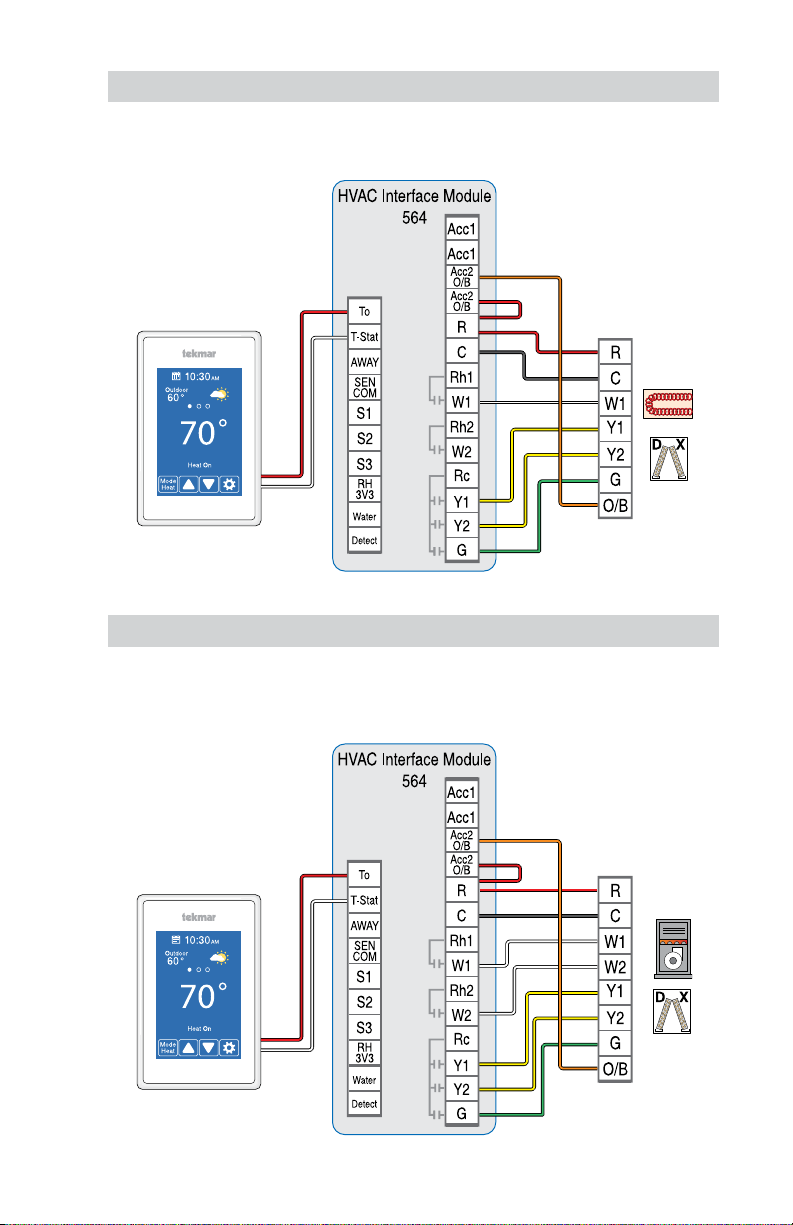
Up to 2-Stage Heat Pump with Auxiliary Heat
The thermostat operates high cost electric resistance heat when the heat pump is unable to meet the
building heating load.
Essential Settings:
Heating Type = Heat Pump
Equipment = 2 Heat Pump/1 Aux
Radiant Floor Heating = No
Jumpers:
J1 = On
J2 = On
J3 = On
Air
Handling
Unit
Up to 2-Stage Heat Pump with 2-Stage Dual Fuel
The thermostat operates the heat pump when the outdoor air temperature is above the balance point
setting and switches to the furnace when below.
Essential Settings:
Heating Type = Heat Pump
Equipment = 2 Heat Pump/2 Aux
Radiant Floor Heating = No
Jumpers:
J1 = On
J2 = On
J3 = On
Air
Handling
Unit
9
Page 10
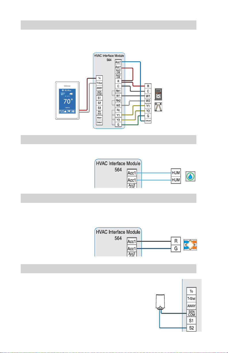
Dehumidification using a DX Coil
The thermostat operates the cooling system and runs the system fan at low speed to dehumidify the air.
Essential Settings:
Accessory Relay 1 or 2 = Dehumidifier
Dehumidifier Type = DX Coil
External Jumper
Wires:
R to Acc1
Air
Handling
Unit
Humidifier
The thermostat operates a humidifier to increase relative humidity.
Essential Settings:
Accessory Relay 1 or 2 = Humidifier
Humidifier
HRV/ERV Ventilator
The Heat Recovery Ventilator (HRV) or Energy Recovery Ventilator (ERV) operates to improve
indoor air quality and recovers heat from exhaust air.
Essential Settings:
Accessory Relay 1 = Ventilation
HRV / ERV
Ventilator
Outdoor Sensor
• Installing an outdoor sensor provides more accurate
outdoor temperature readings compared to using
the weather information from the Internet which may
cause delays in updating weather.
• Outdoor temperature is displayed on home screen.
• Used to enable heat pump dual fuel switchover, warm
weather shut down, and cold weather shut down.
tekmar Outdoor
Sensor 070
10
Page 11
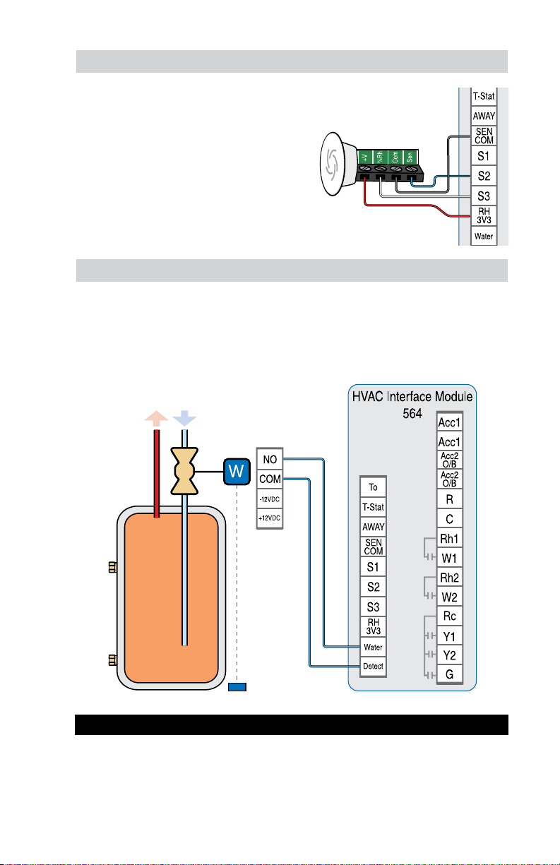
Room Sensor
When the location of the thermostat is not ideal
for accurate temperature and humidity measurement, an optional room sensor can be installed in
a better location. The 086 mounts flush to a wall,
blending in with the room decor.
• Remotely measure the temperature and relative
humidity
•
The Invita WiFi Thermostat provides the option
to disable the internal temperature and relative
humidity sensor, and use the external sensor
instead.
tekmar Humidity &
Temperature Sensor 086
FloodSafe® Water Detector Shutoff
The Watts FloodSafe Water Detector Shutoff LFWDS prevents catastrophic water damage in the
event of a water heater leak.
The thermostat provides an email notification in the event that the FloodSafe Water Detector Shutoff
LFWDS detects a water and shuts off the supply line to the water heater.
Watts FloodSafe
Water Detector Shutoff
Startup
Restore power to the connected equipment. Once energized, the Invita WiFi Thermostat will display
the home screen.
11
Page 12
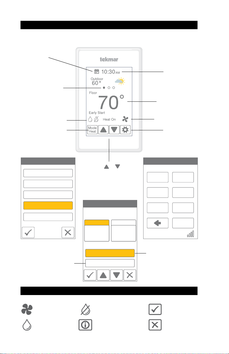
Home Screen
After 60 seconds of inactivity, the thermostat home screen displays only the time and the temperature.
Go to schedule
Swipe to view:
• Weather
• Outdoor temperature
• Floor temperature
• Heat To setting
• Cool To setting
• Relative Humidity
Humidifier or
Dehumidifer operation
Change operating mode
Mode
Emergency Heat
Heat
Cool
Auto Heat-Cool
Off
Save Cancel
‘Save to schedule’ applies
the new temperature to the
current schedule event.
Touch
or to
adjust temperatures
Select either
Heat To or Cool To
Temperature Adjustment
Heat To
70
Hold Until 5:00 PM
Save to Schedule
Cool To
75
Current time
Current temperature
Equipment operation
Heat, Cool and Fan On
Go to settings
MENU SELECTION
AWAY SCHEDULE
DISPLAY TIME
WIFI SETUP
FAN
WIFI: Connected
Hold overrides the
programmed schedule
until the time shown
Symbols
The fan is on
The humidifier is on
12
The dehumidifier is on
The info button provides a
description of the setting
Ok setting change
Cancel setting
change
Page 13
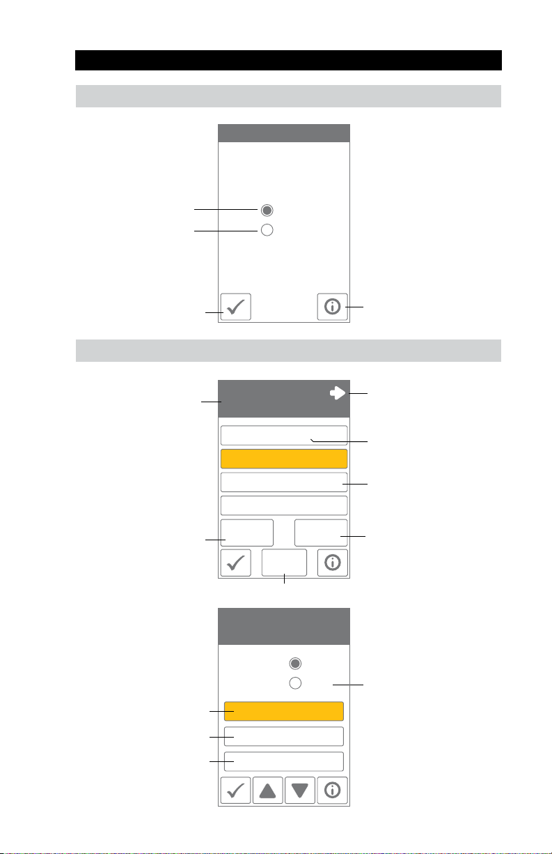
User Settings
Away
Use the Away setting to
save energy when the
building is unoccupied
Operates normally
Operates using the
Away temperature
selected in the
Setup menu
Schedule
Current group of
program days.
Early Start anticipates
time required to
the
heat or cool
and starts early.
Save
a room
Home / Away
At Home
Away
Schedule
Mon Tue Wed Thu Fri
Wake 6:00 AM 70° 75°
Leave 8:00 AM 65° 78°
Return 6:00 PM 70° 75°
Sleep 10:00 PM 65° 78°
Early Start
On
New
Schedule
Schedule
On
Creates a new schedule.
• Selecting the Away setting on a thermostat or
the mobile app will affect
all devices linked to that
location through the app.
• The Away temperature
can be adjusted in the
Setup / Temps menu.
Info
Go to the next group
of program days.
Heating temperature
Cooling temperature
Set to On to follow the
schedule. Set to Off to use
the same temperature all
of the time.
Set schedule start time
Set heating temperature
Set cooling temperature
Schedule Setup
Mon Tue Wed Thu Fri
Wake
6:00 AM
Heat to 70°
Cool to 75°
On
Skip
Select skip if you don’t want
a temperature change.
13
Page 14

Display
Setting Range Default
TEMPERATURE UNITS
Select °F or °C.
ENERGY USE
View the number of hours the heating or cooling has
operated either daily or monthly.
Daily Usage
Today 0 hrs 0 hrs
Yesterday 0 hrs 0 hrs
Tue 0 hrs 0 hrs
Mon 0 hrs 0 hrs
Sun 0 hrs 0 hrs
Sat 0 hrs 0 hrs
Fri 0 hrs 0 hrs
Monthly
Usage
Setting Range Default
BRIGHTNESS ACTIVE
Select the brightness when touching the screen.
BRIGHTNESS INACTIVE
Select the brightness when not in use.
BACKGROUND
Select the background color.
LANGUAGE
Select the language.
SCREEN CLEAN
Locks screen for 10 seconds to allow cleaning.
INACTIVE TIME DISPLAY
Select if the time is visible when the display is inactive.
INACTIVE HUMIDITY DISPLAY
Select if the humidity is visible when the display is inactive.
INACTIVE OUTDOOR DISPLAY
Select if the outdoor temperature is visible when the display
is inactive.
°F or °C °F
0 to 24 (daily)
0 to 744 (monthly)
0 hours
View each day’s run time for
both heating and cooling.
Toggle between Daily and
Monthly Usage.
30 to 100% 100%
Off, 30 to 100% 50%
Light,
Blue,
Night,
Blue
Latte,
Espresso
English,
Español,
English
Français
N/A N/A
Off or On On
Off or On Off
Off or On Off
14
Page 15
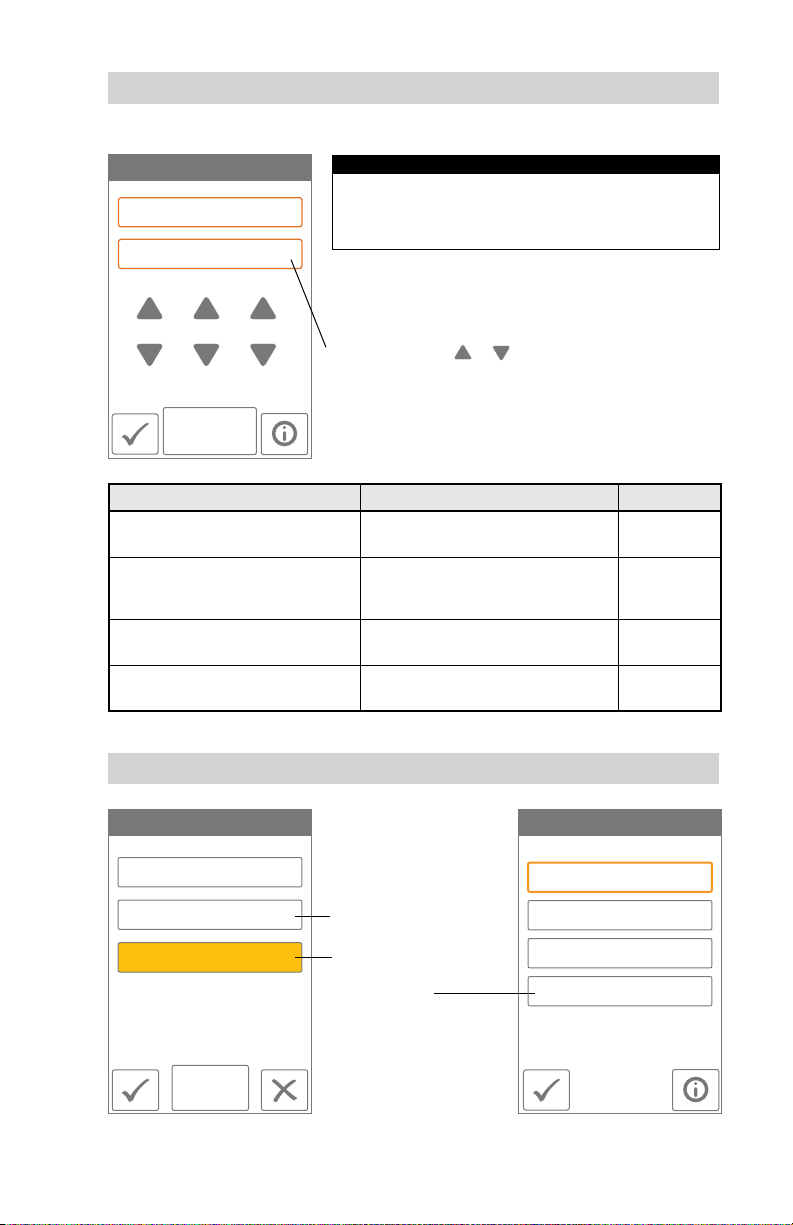
Time
When connected to the Internet, the time can be set automatically.
TIME & DATE
Aug 25 2019
1 30 PM
NOTICE
Incorrectly setting the time and date manually may prevent
the thermostat from communicating to the mobile app.
Automatic time source is recommended when using an
Internet connection.
OPTIONS
The time and date can be manually set by highlighting a field
and then using the
Choose from the time options listed below.
or buttons.
Setting Range Default
TIME FORMAT
Select the time format.
TIME SOURCE
If Internet is available, the time source can
be either automatically or manually set.
TIME ZONE
Select the local time zone.
DAYLIGHT SAVING TIME
Select the brightness when not in use.
Central, Eastern, Atlantic, Newfoundland
12 or 24 hour 12 hour
Automatic, Manual Auto
Hawaii, Alaska, Pacific, Mountain,
Off, On On
Eastern
Fan
Fan
On
Auto
Follow Schedule
The fan is normally off when
set to auto but turns on
when needed for the heating
or cooling equipment.
When a programmable
schedule is used, there
is a fan setting for each
time period.
Wake On
Leave Auto
Return On
Sleep Auto
Fan
Setup Fan
Schedule
15
Page 16
WiFi
NOTICE
Before using the WiFi features of this product, you must accept the Terms of Use, as amended
from time to time and available at Watts.com/terms-of-use. If you do not accept these terms, this
product can still be used without WiFi features.
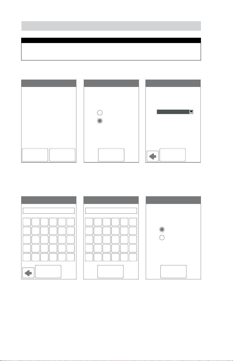
The thermostat includes a step by step tutorial to setup the WiFi connection.
Tutorial
Before first using WiFi features
of this product, you must accept
the Terms of Use available at
https://www.watts.com/terms-of-use
by pressing AGREE below.
If you do not accept these terms.
this product can still be used
without WiFi features.
DISAGREE AGREE
Step 1
Agree to Terms of Use
Enter Password
A C EB D F
G I KH J L
M O QN P R
S U WT V X
Y A/1Z Shft Del
WIFI
Off
On
NEXT
Step 2
Turn on WiFi
ZIP/Postal
1 3 52 4 6
7 9 -8 0 /
: ( $; ) &
@ . ?" , !
' A/1\ Shft Del
NETWORK SSID
Select a network
from the list:
Your House
CONNECT
Step 3
Enter wireless network name.
It must support WPA2
security encryption.
Time Source
Automatic
Manual
CONNECT
Step 4
Enter WiFi password.
16
OK
Step 5
Enter ZIP or postal code. This
determines your location for
weather information.
NEXT
Step 6
Select if the time is set
automatically from the
Internet or manually.
Page 17
WiFi and Connectivity Troubleshooting
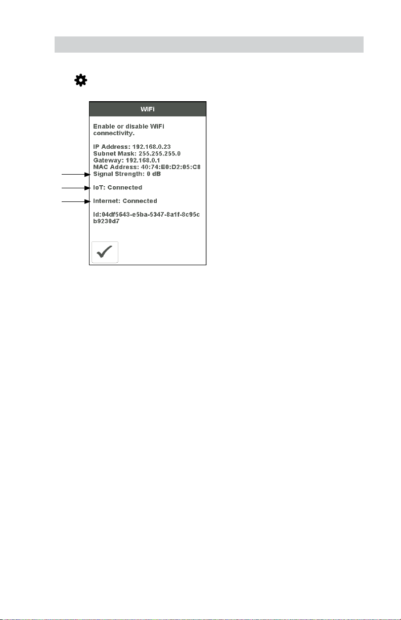
WiFi Connection Status
Press
thermostat connection status.
> WiFi > WiFi:On > i to view the
1
3
2
(1) WiFi Signal Strength
• The WiFi signal must measure between 0 and
-69 dB to have a reliable connection to the
Watts cloud.
• A WiFi extender is recommended to be
installed if the WiFi signal is between
-70 to -100 dB.
(2) Internet Connected
• The WiFi information screen will show Internet
Connected when the thermostat is connected
to the router and there is a connection to
the Internet.
(3) IoT Connected
• The thermostat connection status will show
IoT Connected when connected to the Watts
Cloud and the thermostat is ready to be
registered to the app.
If IoT is not connected, please follow these steps:
Check Password
• Double check that you are using the correct
WiFi network and password.
• The password is limited to 32 characters,
and can include upper and lower case letters,
numbers, special characters and spaces. A
space counts as a character.
• The thermostat supports WPA2-Personal
password security.
Power Off and On
• Power the thermostat off. Next, power the router off, wait 10 seconds, then power on and wait
for the Internet status to be on. Then power the
thermostat on.
Check Router & Firewall
Consult the router manual or Internet Service
Provider (ISP) for assistance with router setup with
these configurations:
• The router must provide a 2.4 GHz signal.
The thermostat is not compatible with
5 GHz networks.
• The router is using WPA2-Personal security.
• The router has DHCP enabled with enough
available addresses for all Internet devices.
• The router firewall is not blocking the outbound
UDP or TCP ports: 53, 123, 443, 8883.
• The router firewall is not blocking connections
to *.azure-devices.net
The router firewall is not blocking the thermostat
based upon a MAC filter list.
Network Troubleshooting
• tekmar provides free access to a network
troubleshooting tool called RouteThis Helps.
• Download the app from the App Store or
Google Play Store to your mobile device.
• Enter code “TEKM” and click “Network scan”.
The app will provide further instructions.
Create a WiFi Hotspot
If you are unable to connect to the WiFi network,
try creating a WiFi Hotspot on your mobile device
to bypass the router.
Apple* iOS WiFi hotspot instructions
https://support.apple.com/en-us/HT204023
Android** WiFi hotspot instructions
https://support.google.com/android/answer/9059108
If the thermostat displays IoT connected when
using the WiFi Hotspot, please contact your
Internet Service Provider (ISP) or IT professional
for assistance with the router.
* Apple and App Store are trademarks of
Apple Inc.
** Google, Android and Google Play are trade-
marks of Google LLC.
17
Page 18
Installer Settings
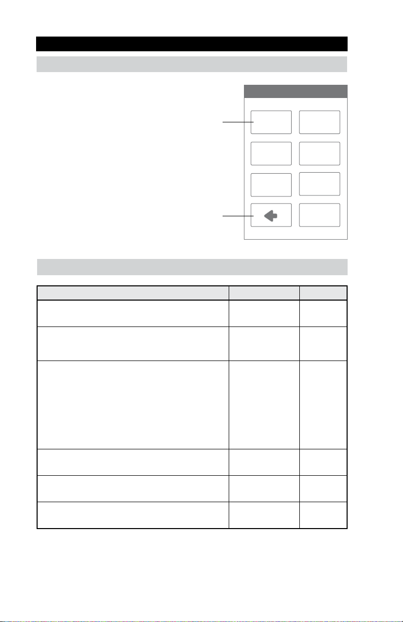
Setup
The Setup menu contains seven sub-menus that
determine how the thermostat operates.
The Access Level setting in the Toolbox menu
determines how many settings are available to the user.
Press back to return to the main
Settings menu.
SETUP MENU
TOOLBOX TEMP
SENSORS
RELAYS
ALERTS
HUMIDITY
VENT
Setup - Toolbox
Setting Range Default
ERROR
Displays any error messages.
ACCESS LEVEL
Select between user and installer access levels. User access
level restricts access in the Setup Menu.
STATUS
The current status of warm weather shut down, cold weather
shut down and each of the relays.
SOFTWARE VERSION
Display the software version.
LOAD DEFAULTS
All settings are returned to factory defaults.
CALIBRATE TOUCHSCREEN
Recalibrate the screen after loading factory defaults.
N/A N/A
User,
Installer
Early Start,
WWSD,
CWSD,
W1,
W2,
Y1,
Y2,
G,
Acc1,
Acc2
N/A N/A
Yes,
No
N/A N/A
Installer
N/A
No
18
Page 19
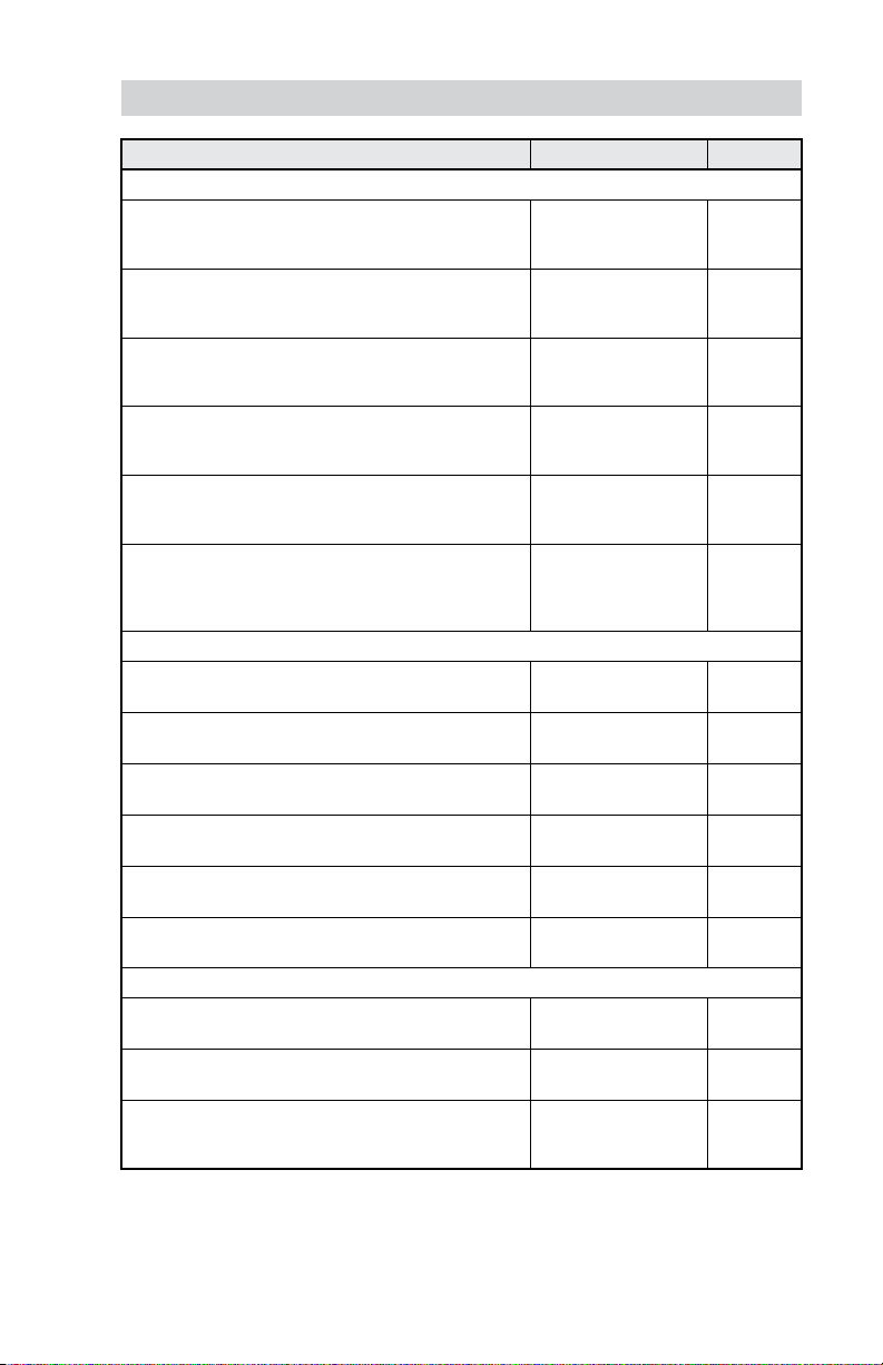
Setup - Temp
Setting Range Default
Screen Page 1
FLOOR MIN - WAKE
Select the floor temperature while in the wake schedule.
Applies when there is both a floor and an air sensor.
FLOOR MIN - LEAVE
Select the floor temperature while in the leave schedule.
Applies when there is both a floor and an air sensor.
FLOOR MIN - RETURN
Select the floor temperature while in the return schedule.
Applies when there is both a floor and an air sensor.
FLOOR MIN - SLEEP
Select the floor temperature while in the sleep schedule.
Applies when there is both a floor and an air sensor.
FLOOR MIN - AWAY
Select the floor temperature while in away.
Applies when there is both a floor and an air sensor.
FLOOR MAX
Select the maximum floor temperature. This protects the
floor covering from over heating. Applies when there is a
floor sensor.
Screen Page 2
HEAT TO AWAY
Select the heating temperature when away.
HEAT TO MIN LIMIT
Select the minimum heating temperature limit.
HEAT TO MAX LIMIT
Select the maximum heating temperature limit.
COOL TO AWAY
Select the cooling temperature when away.
COOL TO MIN LIMIT
Select the minimum cooling temperature limit.
COOL TO MAX LIMIT
Select the maximum cooling temperature limit.
Screen Page 3
WARM WEATHER SHUT DOWN
Select the outdoor temperature at which the heating is shut off.
COLD WEATHER SHUT DOWN
Select the outdoor temperature at which the cooling is shut off.
HEAT PUMP BALANCE POINT
Select the outdoor temperature at which the heat pump is
shut off and the backup heat source is operated exclusively.
Off, 40 to 95°F
Off, 4.5 to 35.0°C
Off, 40 to 95°F
Off, 4.5 to 35.0°C
Off, 40 to 95°F
Off, 4.5 to 35.0°C
Off, 40 to 95°F
Off, 4.5 to 35.0°C
Off, 40 to 95°F
Off, 4.5 to 35.0°C
Off, 40 to 95°F
Off, 4.5 to 35.0°C
Off, 40 to 95°F
Off, 4.5 to 35.0°C
Off, 40 to 95°F
Off, 4.5 to 35.0°C
Off, 40 to 95°F
Off, 4.5 to 35.0°C
Off, 45 to 100°F
Off, 7.0 to 38.0°C
Off, 45 to 100°F
Off, 7.0 to 38.0°C
Off, 45 to 100°F
Off, 7.0 to 38.0°C
Off, 40 to 100°F
Off, 4.5 to 38.0°C
Off, 40 to 100°F
Off, 4.5 to 38.0°C
Off, -22 to 70°F
Off, -30.0 to 21.0°C
Off
Off
Off
Off
Off
Off
62°F
16.5°C
Off
Off
Off
Off
Off
Off
Off
Off
19
Page 20
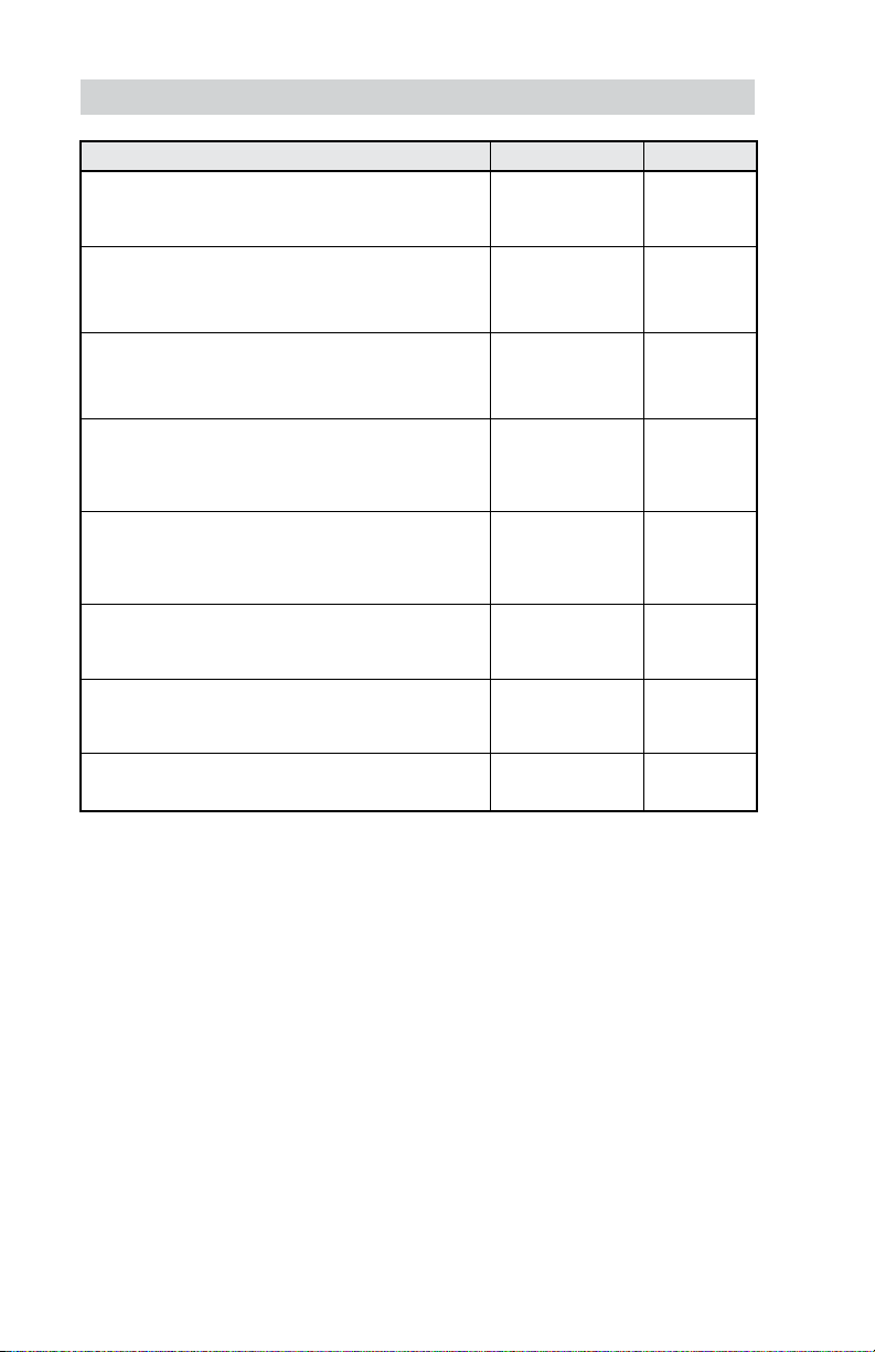
Setup - Sensors
Setting Range Default
SENSOR 1
Select the type of sensor connected to S1 and Com
wiring terminals.
SENSOR 2
Select the type of sensor connected to S2 and Com
wiring terminals.
SENSOR 3
Select the type of sensor connected to S3 and Com
wiring terminals.
INTERNAL ROOM SENSOR
Select if the internal room temperature sensor is on or off.
Only available when Sensor 1, 2 or 3 is set to read a room
or floor sensor.
INTERNAL HUMIDITY SENSOR
Select if the internal humidity sensor is on or off. Only
available when Sensor 3 is set to read an external
humidity sensor.
ROOM OFFSET
Manual offset correction of the room temperature
measurement.
FLOOR OFFSET
Manual offset correction of the floor temperature
measurement.
HUMIDITY OFFSET
Manual offset correction of the relative humidity measurement.
Off,
Room,
Floor
Off,
Room,
Floor,
Outdoor
Off,
Room,
Floor,
Humidity
Off,
On
Off,
On
Off,
-5 to +5°F
-3.0 to 3.0°C
Off,
-5 to +5°F
-3.0 to 3.0°C
Off,
-10% to +10%
Off
Off
Off
On
On
Off
Off
Off
20
Page 21
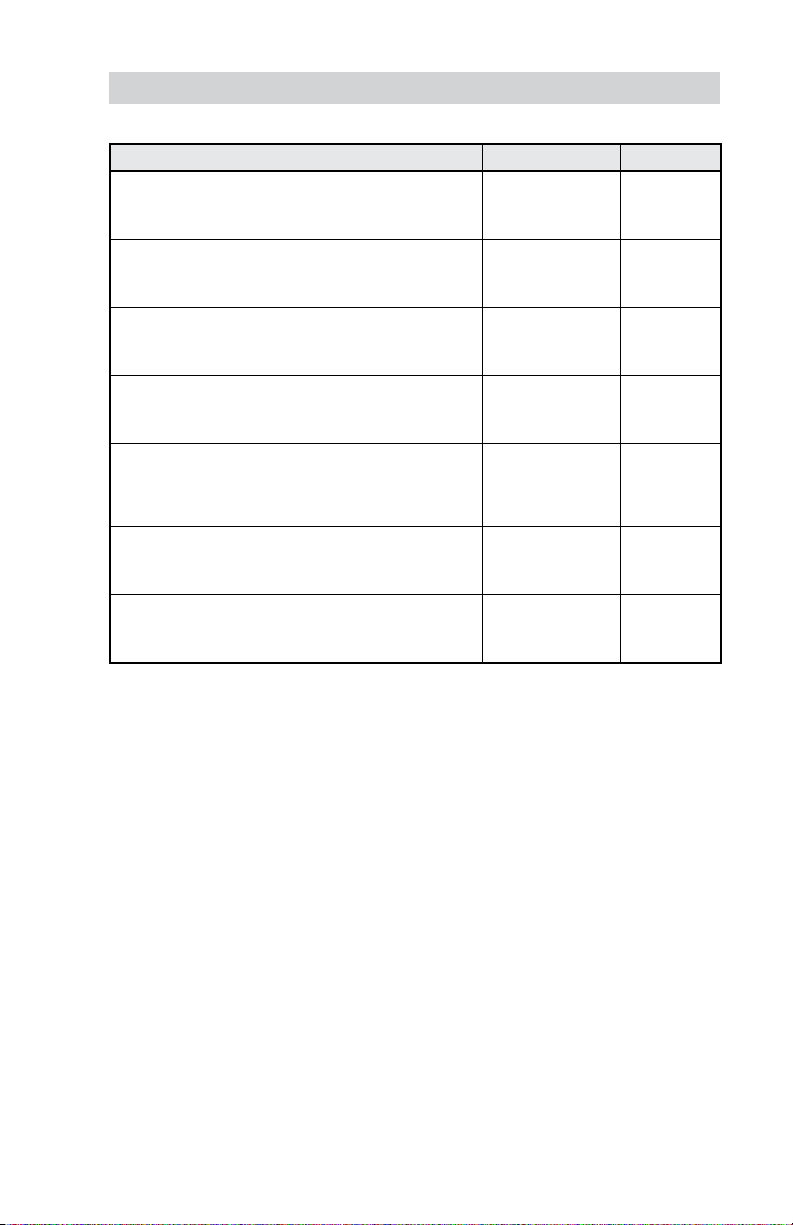
Setup - Alerts
Setting Range Default
ROOM HOT WARNING
Sends an email notification if the room exceeds this
temperature.
ROOM COLD WARNING
Sends an email notification if the room falls below this
temperature.
LOW HUMIDITY WARNING
Sends an email notification if the humidity falls below
this setting.
HIGH HUMIDITY WARNING
Sends an email notification if the humidity rises above
this setting.
AUXILIARY HEAT RUN TIME WARNING
Sends an email notification if the auxiliary heat W1 or W2
runs continuously for longer than this setting. This setting
only applies for heat pump systems.
AIR FILTER CHANGE WARNING
Sends an email notification to change the air filter when the
fan exceeds this run time.
UV LAMP CHANGE WARNING
Sends an email notification to change the UV disinfectant
lamp when it exceeds this run time.
Off, 40 to 100°F
Off, 4.5 to 38.0°C
Off, 40 to 100°F
Off, 4.5 to 38.0°C
Off, 5 to 95% Off
Off, 5 to 95% Off
Off, 1 to 24 hours Off
Off, 200 to
2000 hours
Off, 10,000 to
50,000 hours
Off
Off
Off
Off
21
Page 22
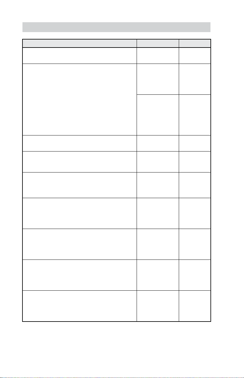
Setup - Relays (1 of 3)
Setting Range Default
HEATING TYPE
Select between conventional heating or heat pump.
EQUIPMENT
Select the number of stages of the heating and
cooling equipment.
RADIANT FLOOR HEATING
Select if the first stage W1 heats a radiant floor.
HEAT 1 DIFFERENTIAL
Select when the first stage heating turns on. Turn on point is
the Heat To setting minus the differential.
HEAT 2 DIFFERENTIAL
Select when the second stage heating turns on. Turn on
point is the Heat To setting minus the differential. This
setting is available when there are at least 2 heating stages.
HEAT 2 DELAY
Select the time delay when the second stage heating turns
on. The time delay starts counting after the first stage
heating is turned on. This setting is available when there
are at least 2 heating stages.
HEAT 3 DIFFERENTIAL
Select when the third stage heating turns on. Turn on point
is the Heat To setting minus the differential. This setting is
available when a heat pump is selected and there are at
least 3 heating stages.
HEAT 3 DELAY
Select the time delay when the third stage heating turns on.
The time delay starts counting after the second stage heating is turned on. This setting is available when a heat pump
is selected and there are at least 3 heating stages.
HEAT 4 DIFFERENTIAL
Select when the fourth stage heating turns on. Turn on point
is the Heat To setting minus the differential. This setting is
available when a heat pump is selected and there are 4
heating stages.
Conventional,
Heat Pump
Conventional
1 Heat/1 Cool,
1 Heat/2 Cool,
2 Heat/1 Cool,
2 Heat/2 Cool,
Heat Pump
1 HP,
1 HP/1 Aux,
1 HP/2 Aux,
2 HP,
2 HP/1 Aux,
2 HP/2 Aux
Yes or No No
0.9 to 2.0°F
0.5 to 1.05°C
1.0 to 10.0°F
0.6 to 5.6°C
0 to 180 minutes 1 minute
1.0 to 10.0°F
0.6 to 5.6°C
0 to 180 minutes 1 minute
1.0 to 10.0°F
0.6 to 5.6°C
Conventional
1 Heat/
1 Cool
1 HP/1 Aux
°
1.4
0.75
°
2.0
°
1.2
°
2.5
°
1.4
°
3.0
°
1.8
F
°
C
F
C
F
C
F
C
22
Page 23
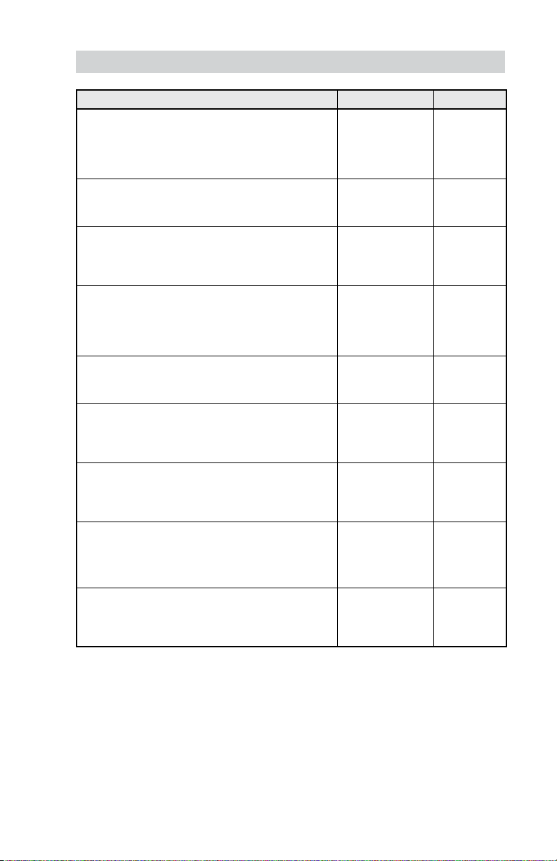
Setup - Relays (2 of 3)
Setting Range Default
HEAT 4 DELAY
Select the time delay when the fourth stage heating turns
on. The time delay starts counting after the third stage
heating is turned on. This setting is available when a heat
pump is selected and there are at least 4 heating stages.
COOL 1 DIFFERENTIAL
Select when the first stage cooling turns on. Turn on point is
the Cool To setting plus the differential.
COOL 2 DIFFERENTIAL
Select when the second stage cooling turns on. Turn on
point is the Cool To setting plus the differential. This setting
is available when there are two cooling stages.
COOL 2 DELAY
Select the time delay when the second stage cooling turns
on. The delay time starts counting after the first stage
cooling is turned on. This setting is available when there
are two cooling stages.
Y MIN RUN TIME
Select the minimum time the cooling compressor must run
before shutting off. This helps prevent compressor failure.
Y MIN OFF TIME
Select the minimum time the cooling compressor must be
off before turning back on. This helps prevent compressor
failure.
DUAL FUEL
Select dual fuel on if the heat pump has 100% backup
using a furnace or hydronic fan coil. The setting is available
for heat pump systems with auxiliary heat.
ACCESSORY RELAY 1
Select the type of equipment that the accessory relay
1 operates.
ACCESSORY RELAY 2
Select the type of equipment that the accessory relay 2
operates. This setting is only available for conventional
heating systems.
0 to 180 minutes 1 minute
0.9 to 2.0°F
0.5 to 1.05°C
1.0 to 10.0°F
0.6 to 5.6°C
0 to 180 minutes 1 minute
0:30 to 10:00 minutes 2:00 minutes
0:30 to 10:00 minutes 5:00 minutes
Off or On Off
Off,
Humidifier,
Dehumidifier,
Ventilation,
HP Loop Valve
Off,
Humidifier,
Dehumidifier
1.4
0.75
2.0
1.2
Off
Off
°
F
°
C
°
F
°
C
23
Page 24
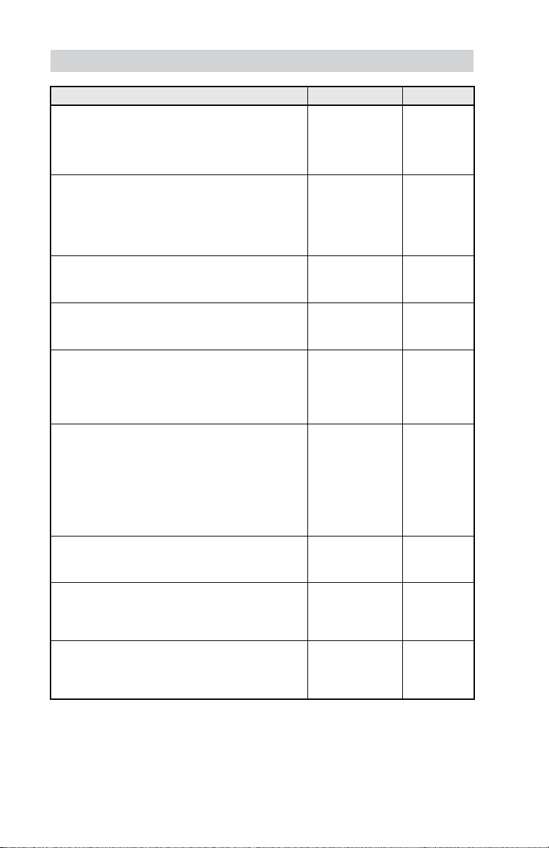
Setup - Relays (3 of 3)
Setting Range Default
HEAT PUMP REVERSING VALVE
Select O for heat pumps designed for normally heating
operation. Select B for heat pumps designed for normally
cooling operation. This setting is only available for heat
pump systems.
FAN RELAY
Select which relays require fan operation. Combinations
with W1 are not available when Radiant Floor Heating is set
to yes.
FAN WITH HRV/ERV
Select if the HVAC system fan should turn on together with
the HRV or ERV ventilation fan.
HUMIDIFIER TYPE
Select the type of humidifier. This setting is available when
Accessory 1 or 2 is set to Humidifier.
WINDOW PROTECTION
Select if the relative humidity setpoint should automatically
adjust with outdoor temperature to prevent frost on windows.
This setting is available when Accessory 1 or 2 is set to
Humidifier and a wired outdoor sensor is installed.
WINDOW QUALITY
The window quality determines the amount that the relative
humidity setting is lowed during cold outdoor weather.
Choose the highest number of panes installed and best quality
as a starting point. If window condensation appears, lower
the setting until condensation stops forming. This setting is
available when Accessory 1 or 2 is set to Humidifier and
a wired outdoor sensor is installed.
DEHUMIDIFIER TYPE
Select the type of dehumidifier. This setting is available when
Accessory 1 or 2 is set to Dehumidifier.
HEAT-COOL TIME INTERLOCK
When operating in Mode Auto, select the amount of time
to wait between switching from heating to cooling and
vice versa.
WARM FLOOR DURING COOLING
Select whether the floor should be heated when in cooling
mode. This setting is only available when Radiant Floor
Heating is set to yes.
O (Orange),
B (Blue)
G only,
With Y
With Y and W1,
With Y and W2,
With Y, W1 and W2
Off or On Off
Evaporative,
Steam,
Stand Alone
Off or On Off
1 Pane
2 Pane
3 Pane
Poor
Average
Better
DX Coil,
Stand Alone
10 to 180 minutes 10 minutes
Yes or No No
O
G only
Steam
2 Pane
Average
DX Coil
24
Page 25
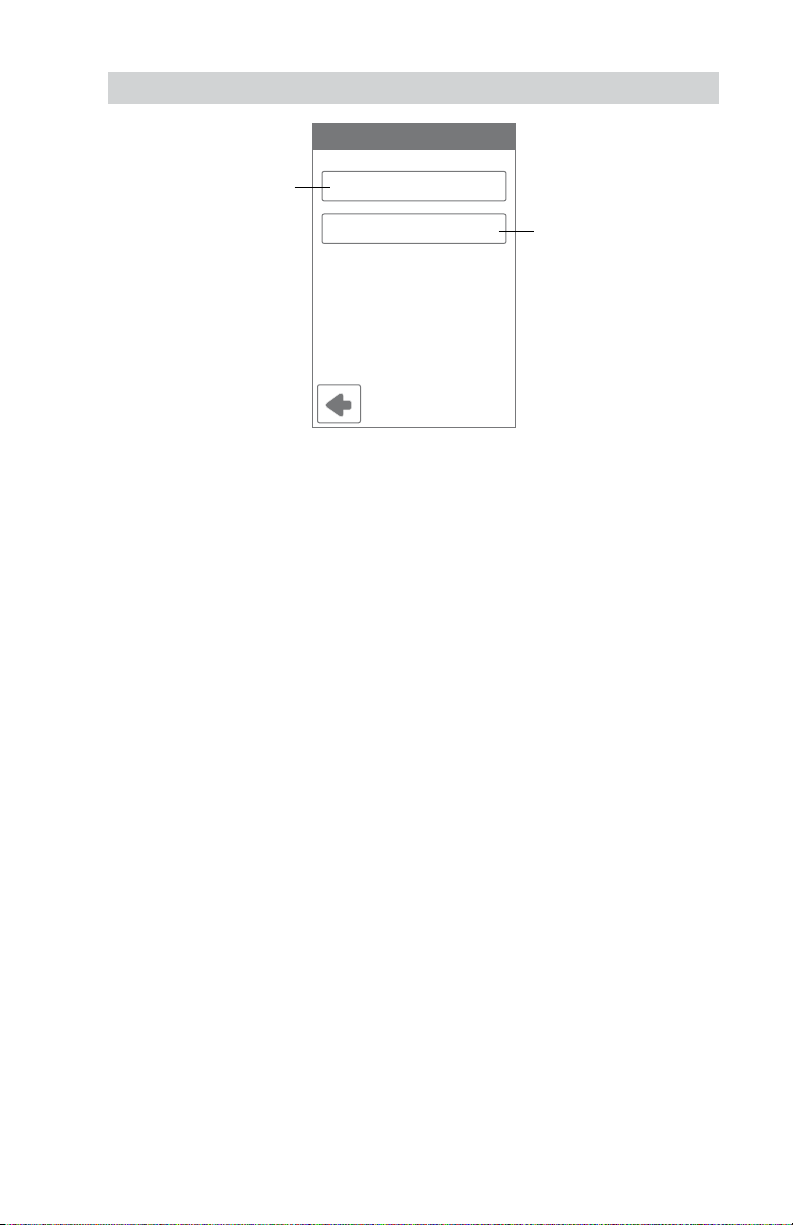
Setup - Humidity
Set the lowest relative
humidity level.
Range is 10 to 80%
Default is 40%
Available when Accessory 1
or 2 operates a humidifier.
Humidity
Humidify To: 40%
Dehumidify To: 60%
Set the highest relative
humidity level.
Range is 20 to 90%
Default is 60%
Available when Accessory 1
or 2 operates a dehumidifier.
25
Page 26
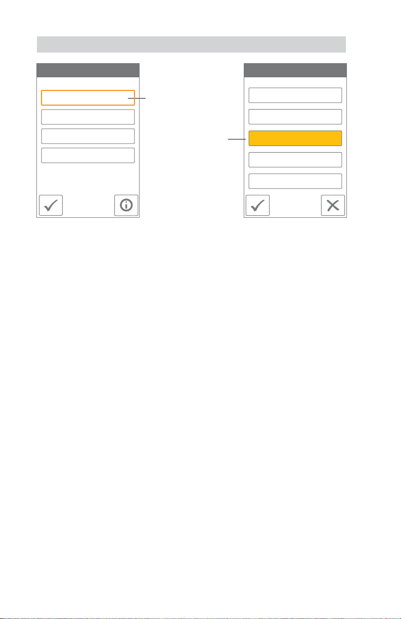
Setup - HRV / ERV Ventilation
VENTILATION FAN
Wake 30 min/hr
Leave Auto
Return 45 min/hr
Sleep Auto
When a programmable
schedule is used, there is a
ventilation setting for each
time period.
The ventilation fan runs
for the set amount of
time per hour.
VENTILATION Wake
On
45 min/hr
30 min/hr
15 min/hr
Off
26
Page 27
Sequence of Operation
Heating and Cooling Operation
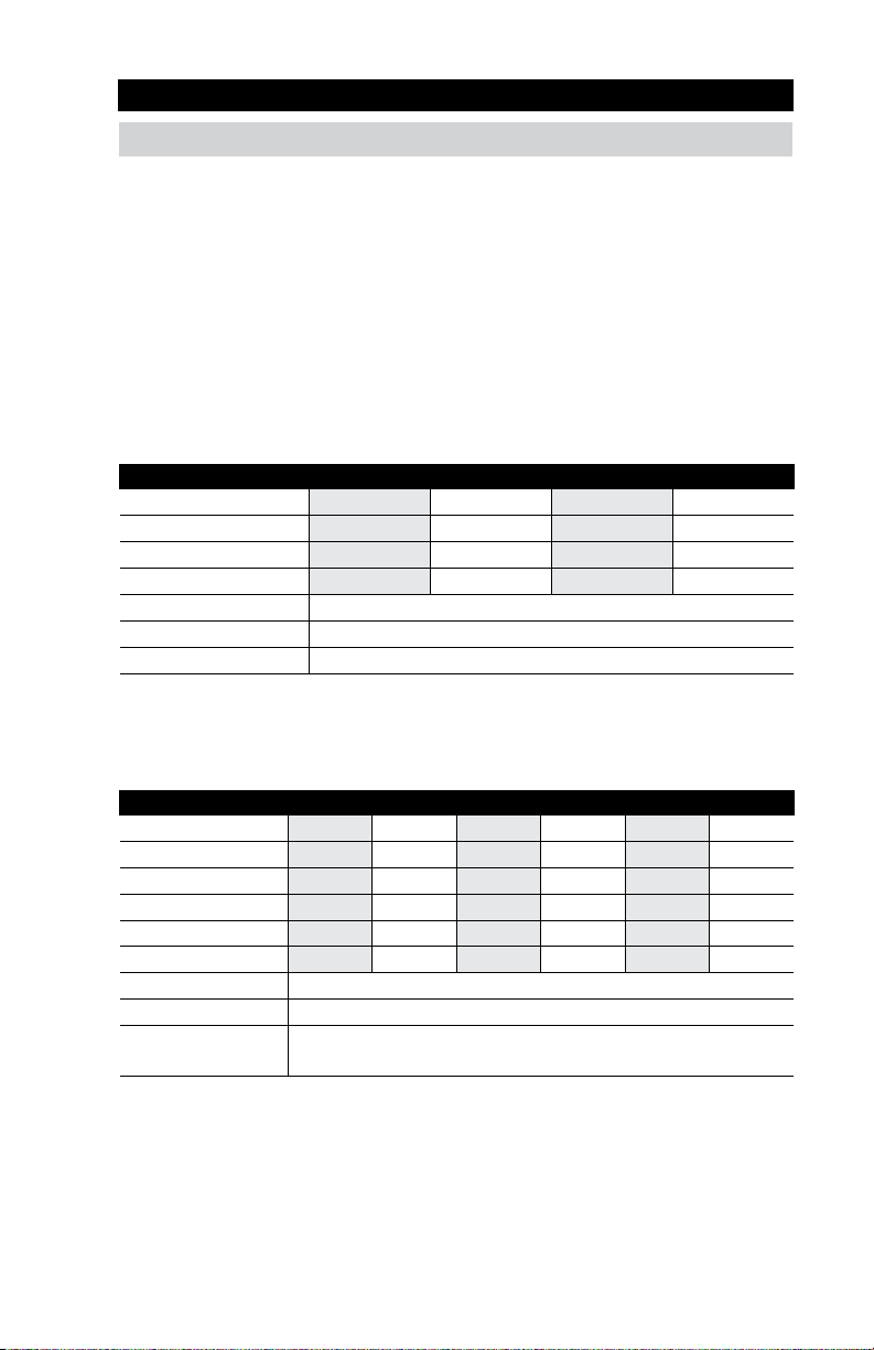
• The heating setpoint can be set from 40 to 95°F (4.5 to 35°C).
• The Heat On symbol is shown on the display when the thermostat is heating.
• The cooling setpoint can be set from 45 to 100°F (7.0 to 38.0°C).
• Heating for freeze protection is provided whenever the air or floor temperature falls below 40
regardless of operating mode.
•
The Cool On symbol is shown on the display when the thermostat is cooling.
The thermostat supports two heating system types: 1) conventional, or 2) heat pump.
Conventional Systems
A conventional heating system includes: furnaces, air conditioners, hydronic heating systems with
baseboards, radiant floors, or fan coils and electric heating.
The thermostat supports up to two heating stages, two cooling stages, a fan and two accessory relays.
EQUIPMENT SETTING 1H/1C 1H/2C 2H/1C 2H/2C
First stage heating W1 W1 W1
Second stage heating - - W2
First stage cooling Y1 Y1 Y1
Second stage cooling - Y2 Fan G
Accessory 1 Choice of: Humidifier, Dehumidifier, HRV/ERV
Accessory 2 Choice of: Humidifier, Dehumidifier
Heat Pump Systems
A heat pump system may include additional heat sources as backup. The thermostat supports up to
four heating stages, two cooling stages, a reversing valve, a fan and one accessory relay.
EQUIPMENT SETTING 1HP 1HP/1AUX 1HP/2AUX 2HP 2HP/1AUX 2HP/2AUX
First stage heating Y1 Y1 Y1 Y1 Y1 Y1
Second stage heating - W1 W1 Y2 Y2 Y2
Third stage heating - - W2 - W1 W1
Fourth stage heating - - - - - W2
First stage cooling Y1 Y1 Y1 Y1 Y1 Y1
Second stage cooling - - - Y2 Y2 Y2
Fan G
Accessory 1 Choice of: Humidifier, Dehumidifier, HRV/ERV ventilator
Accessory 2 Reversing valve O relay remains closed during cooling.
Reversing valve B relay remains closed during heating.
°
F (4.5°C),
W1
W2
Y1
Y2
27
Page 28
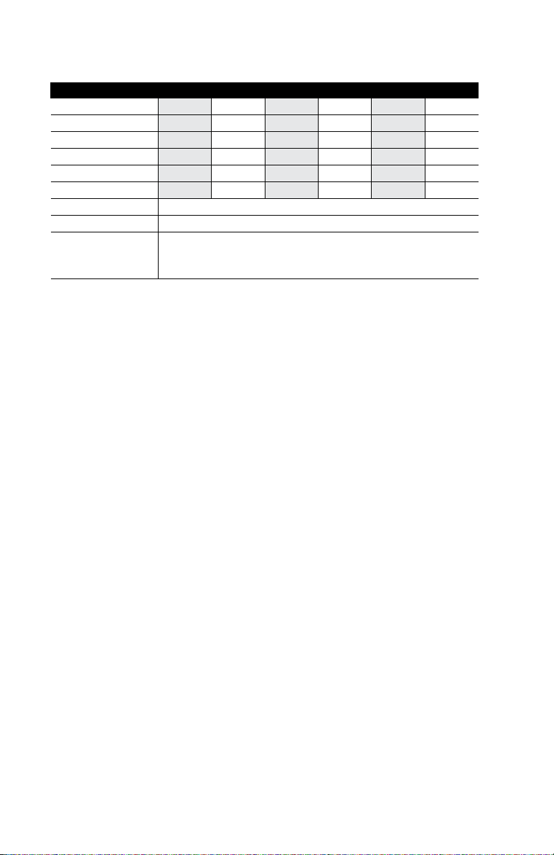
When radiant floor heating is installed, it is always the first stage of heating, followed by the heat
pump, and lastly any backup heating. This allows the floor to remain warm in the heating season.
EQUIPMENT SETTING 1HP 1HP/1AUX 1HP/2AUX 2HP 2HP/1AUX 2HP/2AUX
First stage heating Y1 W1 W1 Y1 W1 W1
Second stage heating - Y1 Y1 Y2 Y1 Y1
Third stage heating - - W2 - Y2 Y2
Fourth stage heating - - - - - W2
First stage cooling Y1 Y1 Y1 Y1 Y1 Y1
Second stage cooling - - - Y2 Y2 Y2
Fan G
Accessory 1 Choice of: Humidifier, Dehumidifier, HRV/ERV ventilator
Accessory 2 Reversing valve O or B.
O relay remains closed during heating operation.
B relay remains closed during cooling operation.
Heating Differentials
Each heating stage has an adjustable differential and time delay setting to determine when the stage
turns on. The heating stages Heat 4 to Heat 1 shut off are when they reach 1.5, 1.0, 0.5, and 0.0°F
(0.75, 0.5, 0.25, and 0.0°C) of the Heat To setting respectively.
Radiant Floor Heating
Radiant floor heating is operated differently than other heating types due to the large time delays to
heat and cool the slab. When Radiant Floor Heating is selected in the setup menu, the W1 relay operates using Pulse Width Modulation. This improves comfort for radiant systems with high mass floors.
°
• 100% on time at Heat To setting -1.5
• 50% on time at Heat To setting
• 0% on time at Heat To setting + 1.5
F
°
F
Room Sensor and Averaging
The thermostat can measure room temperature between -46 to 212°F (-43 to 100°C). The room
temperature can be measured using a combination of the built-in and auxiliary sensors.
• Built-in room sensor only
• Built-in room sensor with auxiliary room sensor(s) (temperature is averaged)
• Auxiliary room sensor only
Floor Sensor for Radiant Floor Heating
The thermostat can measure floor temperature between -46 to 212°F (-43 to 100°C). If a floor sensor
is connected, floor minimum and maximum settings are available. The floor heating setpoint is adjustable from 40 to 95°F (4.5 to 35°C).
For a combination of air and floor temperature control, leave the internal air sensor on in the setup
menu. A floor minimum can be used to prevent a fast drop in temperature caused by receding solar
exposure. This operation is recommended for areas heated by afternoon sun through large windows.
When the sun sets, it can take a long time for the floors to get warm again. This may cause the room
to cool off too much in the early evening. A floor minimum setting can help with this condition by
maintaining a floor minimum temperature. Keep in mind the floor minimum temperature will override
the air temperature, and if set too high, may overheat the room.
A floor maximum is recommended for rooms with hardwood floors. Setting floor minimum and
maximum temperatures is a way of enhancing the comfort of the living space while protecting
floor coverings.
If there are more than one floor temperature sensors, the temperature is averaged.
It’s possible to heat a radiant floor while the cooling system is operating. This is desirable in locations
such as kitchens and bathrooms. To use this feature, set the Warm Floor During Cooling on.
28
Page 29

Cooling Differentials
The first and second stage cooling have adjustable differentials and time delay setting to determine
when the stage turns on, and shut off when the room temperature reaches 0.5 and 0.0°F (0.25 and
0.0°C) above the Cool To setting respectively.
Heat Pump Balance Point
An air source heat pump’s Coefficient of Performance (COP) declines with falling outdoor air temperature. The Balance Point is the outdoor temperature at which it is more economical to shut off the heat
pump (relays Y1 and Y2) and operate the backup heating equipment (relays W1 and W2).
Dual Fuel
Dual fuel systems include a heat pump together with a backup heat source such as a furnace or a
hydronic fan coil. When Dual Fuel is set to on, the heat pump (relays Y1 and Y2) is shut off whenever
the backup heating equipment (relays W1 and W2) is operating.
Warm Weather Shut Down (WWSD)
The heating system can automatically shut off based upon the outdoor temperature and the WWSD
setting. This provides a convenient way to shut off the heating system.
Cold Weather Shut Down (CWSD)
The cooling system can automatically shut off based upon the outdoor temperature and CWSD
setting. This prevents unwanted cooling during the winter.
29
Page 30

Relative Humidity Operation
Relative Humidity Sensor
The thermostat includes an internal relative humidity (RH) sensor and has the option to connect to an
external RH sensor. The installer has the option to disable the internal RH sensor when an external
RH sensor is installed. When both the internal and external RH sensors are enabled, the RH reading
is averaged.
Humidifier Operation
The thermostat controls the relative humidity (RH) by operating either the Accessory 1 or Accessory 2
relays. This is an installer configurable setting. When the RH is below the Humidify To setting by 3%,
the Accessory 1 or 2 relay is closed to operate a humidifier. The humidifier is shut off when the RH
reaches the Humidify To setting.
The thermostat can operate 3 types of humidifiers:
Stand Alone - The humidifier is not connected to the HVAC system.
- The thermostat Mode can be set to Heat, Cool, Auto or Off.
Steam - The steam humidifier is ducted to the HVAC system.
- The thermostat Mode can be set to Heat, Cool, Auto or Off.
- Requires the system fan to turn on when operating.
Evaporative - A drum style humidifier which requires the heating system to operate
- This system requires the system fan to operate.
- The thermostat Mode must be set to Heat or Auto.
Humidifier Window Protection
During cold weather, condensation will form on windows when the relative humidity (RH) is too high.
The optional window protection feature automatically calculates the indoor dew point based upon the
outdoor temperature and the quality of the windows installed. The humidifier is then operated to the
highest possible RH that is below the Humidify To setting. This feature requires a wired connection to
an Outdoor Sensor 070.
Dehumidifier Operation
The thermostat controls the relative humidity (RH) by operating either the Accessory 1 or Accessory 2
relay. This is an installer configurable setting. When the RH is above the Dehumidify To setting by 3%,
the Accessory 1 or 2 relay is closed to operate the dehumidifier. The dehumidifier is shut off when the
RH reaches the Dehumidify To setting.
The thermostat can operate 2 types of dehumidifiers:
Stand Alone - The dehumidifier is not connected to the HVAC system.
- The thermostat Mode can be set to Heat, Cool, Auto or Off.
DX Coil - The HVAC cooling system is used for dehumidification.
- The Accessory 1 or Accessory 2 relay activates the DHUM operation on the air
- The cooling compressor Y1 and Y2 relays are operated. The chilled DX coil
- The cooling system can over cool the room temperature by 2°F (1°C) during
to evaporate the water.
handling unit to operate the system fan at low speed.
condenses moisture from the air.
dehumidification.
30
Page 31

HRV / ERV Ventilator Operation
Ventilation with fresh outdoor air is important for maintaining indoor air quality. The thermostat can
operate a heat recovery ventilator (HRV) or energy recovery ventilator (ERV) on a timer by closing the
Accessory 1 relay to operate the ventilator fan at low speed.
Heat Pump Loop Valve Operation
The thermostat supports water-to-air heat pump systems that absorb or reject heat to a hydronic
building loop. Whenever the heat pump compressor Y1 or Y2 relay is turned on, the Accessory 1 relay
closes to open a hydronic zone valve. This allows variable speed pumps on the hydronic loop to operate at lower speeds when the heat pump is off, thereby saving electrical energy.
31
Page 32
Error Messages
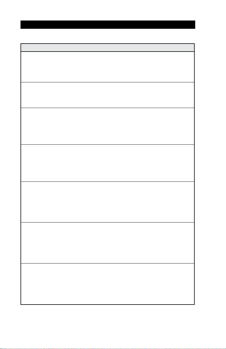
When an error occurs an email notification will be sent to the registered mobile account owner.
Description
COMMUNICATION ERROR
Communication between the display module and the HVAC Interface Module is interrupted. This
error clears automatically once communication is re-established.
This error can occur if the power supply voltage to the HVAC Interface Module is low. Check the
voltage with a volt meter and that the transformer VA rating is enough to power all the equipment.
MEMORY ERROR
The thermostat memory settings are corrupted. To clear, load the factory defaults in the Toolbox
menu. The thermostat will not operate any heating or cooling equipment while this error message
is present.
INTERNAL ROOM SENSOR FAULT
Due to an open or short circuit, the thermostat is unable to read the internal room temperature
sensor. If sensor 1, 2 or 3 is set to room the thermostat continues to operate, otherwise operation
stops.
The error cannot be field repaired. Contact your tekmar sales representative for warranty or repair
procedures.
INTERNAL HUMIDITY SENSOR FAULT
Due to an open or short circuit, the thermostat is unable to read the internal humidity sensor. The
thermostat stops controlling the humidifier or dehumidifier unless an external humidity sensor is
installed on Sensor 3.
The error cannot be field repaired. Contact your tekmar sales representative for warranty or repair
procedures.
SENSOR 1 FAULT
Due to an open or short circuit, the thermostat is unable to read the sensor wired to S1 and Com.
The thermostat stops normal operation if sensor 1 is the only active room or floor sensor or if a floor
maximum temperature has been set.
Check the auxiliary sensor wire for short circuits according to the sensor installation manual. It may
be necessary to replace the auxiliary sensor. Once the error has been corrected, the error message
automatically clears.
SENSOR 2 FAULT
Due to an open or short circuit, the thermostat is unable to read the sensor wired to S2 and Com.
The thermostat stops normal operation if sensor 2 is the only active room or floor sensor or if a floor
maximum temperature has been set.
Check the auxiliary sensor wire for short circuits according to the sensor installation manual. It may
be necessary to replace the auxiliary sensor. Once the error has been corrected, the error message
automatically clears.
SENSOR 3 FAULT
Due to an open or short circuit, the thermostat is unable to read the sensor wired to S3 and Com.
The thermostat stops normal operation if sensor 3 is the only active room sensor or if a floor
maximum temperature has been set.
Check the auxiliary sensor wire for short circuits according to the sensor installation manual. It may
be necessary to replace the auxiliary sensor. Once the error has been corrected, the error message
automatically clears.
32
Page 33
Description
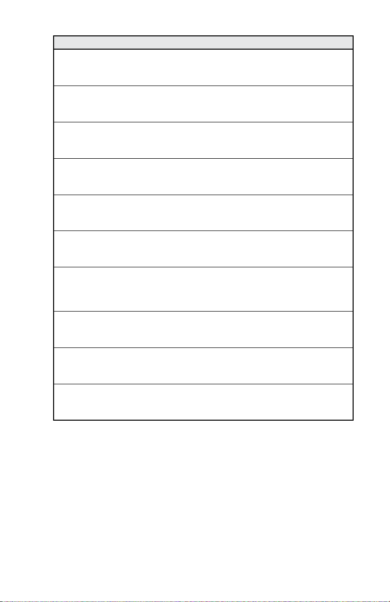
INTERNET UNAVAILABLE
The thermostat has a WiFi connection to the router but is unable to communicate to the Internet.
Steps to clear the error include: 1) power off and on the router, 2) power off and on the thermostat.
WATER LEAK DETECTOR WARNING
A water leak has been detected and the water line has been shut off. The warning will automatically clear
once the water leak detector has been reset.
ROOM HOT WARNING
The room temperature is above the Room Hot Warning setting in the Alerts menu. The warning will
automatically clear once the room temperature falls below the setting.
ROOM COLD WARNING
The room temperature is below the Room Cold Warning setting in the Alerts menu. The warning
will automatically clear once the room temperature rises above the setting.
LOW HUMIDITY WARNING
The relative humidity is below the Low Humidity Warning setting in the Alerts menu. The warning
will automatically clear once the relative humidity rises above the setting.
HIGH HUMIDITY WARNING
The relative humidity is above the High Humidity Warning setting in the Alerts menu. The warning
will automatically clear once the relative humidity falls below the setting.
AUXILIARY HEAT RUN TIME WARNING
The auxiliary heat has been operating continuously longer than the Aux Heat Run Time Warning
setting in the Alerts menu. The error clears when the auxiliary heat turns off. There may be problem
with your heat pump. Contact your heating professional for service.
CHANGE AIR FILTER WARNING
The fan run time has exceeded the Change Air Filter setting in the Alerts menu and requires
replacement. To clear the warning, press the Air Filter Replaced button.
CHANGE UV LAMP WARNING
The UV lamp run time has exceeded the UV Lamp setting in the Alerts menu and requires
replacement. To clear the warning, press the UV Lamp Replaced button.
ZIP/POSTAL CODE ERROR
The thermostat was unable to locate the ZIP or Postal Code entered in the WiFi menu. Please try
again with a ZIP or Postal Code of a nearby area.
33
Page 34

Notes
__________________________________________________________________________________________________________________________________________________________________________
__________________________________________________________________________________________________________________________________________________________________________
__________________________________________________________________________________________________________________________________________________________________________
__________________________________________________________________________________________________________________________________________________________________________
__________________________________________________________________________________________________________________________________________________________________________
__________________________________________________________________________________________________________________________________________________________________________
__________________________________________________________________________________________________________________________________________________________________________
__________________________________________________________________________________________________________________________________________________________________________
__________________________________________________________________________________________________________________________________________________________________________
__________________________________________________________________________________________________________________________________________________________________________
__________________________________________________________________________________________________________________________________________________________________________
__________________________________________________________________________________________________________________________________________________________________________
__________________________________________________________________________________________________________________________________________________________________________
__________________________________________________________________________________________________________________________________________________________________________
__________________________________________________________________________________________________________________________________________________________________________
__________________________________________________________________________________________________________________________________________________________________________
__________________________________________________________________________________________________________________________________________________________________________
__________________________________________________________________________________________________________________________________________________________________________
__________________________________________________________________________________________________________________________________________________________________________
__________________________________________________________________________________________________________________________________________________________________________
__________________________________________________________________________________________________________________________________________________________________________
__________________________________________________________________________________________________________________________________________________________________________
__________________________________________________________________________________________________________________________________________________________________________
__________________________________________________________________________________________________________________________________________________________________________
__________________________________________________________________________________________________________________________________________________________________________
__________________________________________________________________________________________________________________________________________________________________________
__________________________________________________________________________________________________________________________________________________________________________
__________________________________________________________________________________________________________________________________________________________________________
__________________________________________________________________________________________________________________________________________________________________________
__________________________________________________________________________________________________________________________________________________________________________
__________________________________________________________________________________________________________________________________________________________________________
__________________________________________________________________________________________________________________________________________________________________________
__________________________________________________________________________________________________________________________________________________________________________
__________________________________________________________________________________________________________________________________________________________________________
__________________________________________________________________________________________________________________________________________________________________________
__________________________________________________________________________________________________________________________________________________________________________
__________________________________________________________________________________________________________________________________________________________________________
34
Page 35
Technical Data
Invita® WiFi Thermostat 564
Literature Submittal, Installation Operation Manual, User Manual, Job Record, Watts Home Manual
Packaged weight 1.3 lb. (600 g)
Dimensions
Display: 4½" H x 2¾" W x
HVAC Interface Module: 7
Display 3.5" color touchscreen
Enclosure
Display: White or Black PVC plastic, NEMA type 1
HVAC Interface Module: Blue PVC plastic, NEMA type 1
Approvals Meets Class B: ICES & FCC Part 15
Display: Indoor use only, -4 to 122°F (-20 to 50°C), RH ≤90% non-condensing
Ambient conditions
HVAC Interface Module: -40 to 122°F (-40 to 50°C), RH ≤90% non-condensing, out
door use requires mounting in a NEMA 3 enclosure
Environmental Do not use in presence of ammonia (animal barns).
Power supply 21-30 V (ac), 6 VA, Class 2
Relays 30 V (ac) 2 A, Class 2 Circuits
Humidity sensor 0 to 90% ±4% RH
RH Output 3.3 V (dc) humidity sensor power, 3.0 mA maximum
Temperature sensor NTC thermistor, 10 kΩ @ 77°F (25°C ±0.2°C) ß=3892
Optional sensors tekmar type # 070, 072, 073, 076, 077, 079, 084, 086, 087
Communications WiFi 802.11n, 2.4 GHz, WPA2 encryption
Mobile app Apple iOS 12 or higher, Android 10 or higher
Languages English/Français/Español
Warranty 3 Year Limited Warranty
9
⁄16" D (114 x 70 x 14 mm)
7
⁄16" H x 47⁄16" W x 1¼" D (188 x 112 x 31 mm)
-
35
Page 36

Limited Warranty and Product Return Procedure
Limited Warranty The liability of tekmar under this warranty is limited. The Purchaser, by taking receipt of any
tekmar product (“Product”), acknowledges the terms of the Limited Warranty in effect at the time of such Product
sale and acknowledges that it has read and understands same.
The tekmar Limited Warranty to the Purchaser on the Products sold hereunder is a manufacturer’s pass-through
warranty which the Purchaser is authorized to pass through to its customers. Under the Limited Warranty, each
tekmar Product is warranted against defects in workmanship and materials if the Product is installed and used
in compliance with tekmar’s instructions, ordinary wear and tear excepted. The pass-through warranty period is
for a period of twenty-four (24) months from the production date if the Product is not installed during that period,
or twelve (12) months from the documented date of installation if installed within twenty-four (24) months from
the production date.
The liability of tekmar under the Limited Warranty shall be limited to, at tekmar’s sole discretion: the cost of parts
and labor provided by tekmar to repair defects in materials and / or workmanship of the defective product; or to the
exchange of the defective product for a warranty replacement product; or to the granting of credit limited to the
original cost of the defective product, and such repair, exchange or credit shall be the sole remedy available from
tekmar, and, without limiting the foregoing in any way, tekmar is not responsible, in contract, tort or strict product
liability, for any other losses, costs, expenses, inconveniences, or damages, whether direct, indirect, special, secondary, incidental or consequential, arising from ownership or use of the product, or from defects in workmanship
or materials, including any liability for fundamental breach of contract.
The pass-through Limited Warrant y applies only to those defective Products returned to tekmar during the warrant y
period. This Limited Warranty does not cover the cost of the parts or labor to remove or transport the defective
Produc t, or to reinstall th e repaired or replacem ent Product, all su ch costs and expens es being subject to Purchaser’s
agreement and warrant y with its customers.
Any representations or warranties about the Products made by Purchaser to its customers which are dif ferent from
or in excess of the tekmar Limited Warrant y are the Purchaser’s sole responsibility and obligation. Purchaser shall
indemnify and hold tekmar harmless from and against any and all claims, liabilities and damages of any kind or
nature which arise out of or are related to any such representations or warranties by Purchaser to its customers.
The pass-through Limited Warrant y does not apply if the returned Product has been damaged by negligence
by persons other than tekmar, accident, fire, Act of God, abuse or misuse; or has been damaged by modifications, alterations or attachments made subsequent to purchase which have not been authorized by tekmar; or
if the Product was not installed in compliance with tekmar’s instructions and / or the local codes and ordinances; or if due to defective installation of the Product; or if the Product was not used in compliance with
tekmar’s instructions.
THIS WARRANTY IS IN LIE U OF ALL OTHER WARRANTIES, EXPRESS OR IMPLIED, WHICH THE GOV ERNING LAW
ALLOWS PART IES TO CO NTRACTUALLY EXCLUDE, INCLUDING, WI THOUT LIMITATION, IMPLIED WA RRA NTIE S OF
MERCHANTA BILITY AND FITNE SS FOR A PA RTICULAR PURPOSE, DURABILITY OR DESC RIPT ION OF THE PRODUCT, ITS NON-INFRINGEMEN T OF ANY RELEVANT PATENTS OR TR ADEMARK S, AND ITS COMPLIANCE WIT H OR
NON-VIOLATION OF ANY APPLICABLE ENVIRONMENTAL, HEALTH OR SAFETY LEGISLATION; THE TERM OF ANY
OTHER WARR ANT Y NOT HER EBY CON TRACTUALLY EXCLUDED IS LIMITED SUCH THAT IT SHALL NOT E XTE ND
BEYOND TWENTY-FOUR (24) MONTHS FROM THE PRODUCTION DATE, TO THE E XTENT THAT SUCH LIMITATION IS
ALLOWED BY TH E GOVERNING L AW.
Product Warranty Return Procedure All Products that are believed to have defects in workmanship or materials
must be returned, together with a written description of the defect, to the tekmar Representative assigned to the
territory in which such Product is located. If tekmar receives an inquiry from someone other than a tekmar Representative, including an inquiry from Purchaser (if not a tekmar Representative) or Purchaser’s customers, regarding
a potential warrant y claim, tekmar’s sole obligation shall be to provide the address and other contact information
regarding the appropriate Representative.
Need help? Go to our website or contact us.
tekmarControls.com | [email protected] | 1-800-438-3903
All specifications are subject to change without notice
Tel: 1-800-438-3903 • Fax: (250) 984-0815
IO M-T- 56 4 2315 © 2023 tekmar
tekmarControls.com
 Loading...