

Page 1
Installation & Operation Manual
H3021A
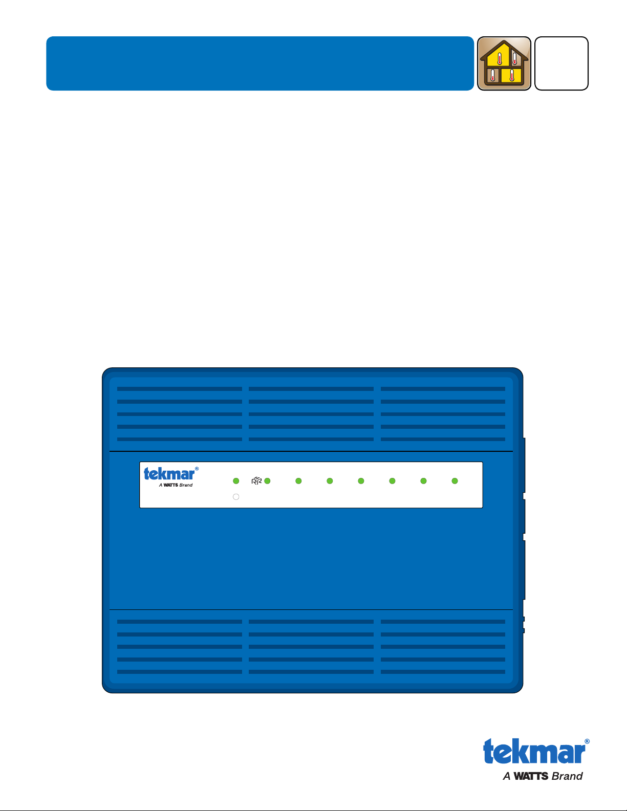
Switching Relay 306P
Six Zon es with P riority
RoomResponse
TM
Power
Priority
Zone 1 Zone 2 Zone 3 Zone 4 Zone 5 Zone 6
306P_D
Switching Relay 306P
Zoning
11/16
Replaces: 10/16
Introduction
The Switching Relay
heating system. Zone 1 has optional priority over zones 2 through 6 and can be used to provide heat to an indirect
domestic hot water tank. The 306P includes optional exercising to prevent circulator seizure when not in use, and optional
post purge operation of the last operating zone to maximize energy savings. The 306P provides a RoomResponseTM
signal to modulating-condensing boilers to optimize comfort while improving boiler efficiency.
306
P connects up to six thermostats and operates circulators to provide heating to a zoned hydronic
Features
• RoomResponseTM signal
• Compatible with all 24 V(ac) thermostats
• Unlimited zone expansion
• Zone priority
• Priority override
• Pump exercising
• Post purge
•
LED for each zone, priority, end switch and RoomResponse
• Away signal shared between thermostats
• Four ground screws
• Top, bottom and back conduit knockouts
• Fuses protect transformers and pumps
• Two spare fuses included
• CSA approved
TM
© 2016 tekmar 306P_D - 11/16
Page 2

Table of Contents
Important Safety Information .............................................2
Installation .........................................................................3
Preparation .................................................................... 3
Location ......................................................................... 3
Installing the Enclosure ................................................. 3
Application 306P–1 ........................................................4
Application 306P–2 ....................................................... 5
Application 306P–3 ....................................................... 6
User Interface ....................................................................7
Indicator LED ................................................................. 7
Sequence of Operation .....................................................7
Technical Data ..................................................................12
Limited Warranty and Product Return Procedure ............12
Important Safety Information
It is your responsibility to ensure that this control is safely installed according to all applicable codes and standards. tekmar is
not responsible for damages resulting from improper installation and/or maintenance.
This is a safety-alert symbol. The safety alert symbol is shown alone or used with a signal word (DANGER,
WARNING, or CAUTION), a pictorial and/or a safety message to identify hazards. When you see this symbol
alone or with a signal word on your equipment or in this manual, be alert to the potential for death or serious
personal injury.
This pictorial alerts you to electricity, electrocution, and shock hazards.
This symbol identifies hazards which, if not avoided, could result in death or serious injury.
This symbol identifies hazards which, if not avoided, could result in minor or moderate injury.
This symbol identifies practices, actions, or failure to act which could result in property damage or damage to
the equipment.
Read manual and all product labels BEFORE using the equipment. Do not use unless you know
the safe and proper operation of this equipment. Keep this manual available for easy access by all
users. Replacement manuals are available at tekmarControls.com
•
It is the installer’s responsibility to ensure that this control is safely installed according to all applicable codes and
standards.
•
Improper installation and operation of this control could result in damage to the equipment and possibly even personal
injury or death.
• This control is not intended for use as a primary limit control. Other controls that are intended and certified as safety limits
must be placed into the control circuit.
The control includes fuses and transformer that are serviceable. Do not attempt to service any other parts on the control.
Attempting to service the control voids the warranty.
• Strip all wiring to a length of 3/8 in. or 10 mm for all terminals.
• A circuit breaker or power disconnect that provides power to the control should be located nearby and clearly labeled.
• Refer to the current and voltage ratings at the back of this manual before connecting devices to this control.
© 2016 tekmar 306P_D - 11/16
2 of 12
Page 3
Radio Frequency Interference
The installer must ensure that this control and its wiring are
isolated and/or shielded from strong sources of electromagnetic
noise. Conversely, this Class B digital apparatus complies
with Part 15 of the FCC Rules and meets all requirements of
the Canadian Interference-Causing Equipment Regulations.
However, if this control does cause harmful interference to
radio or television reception, which is determined by turning
Installation
Preparation
Tools Required
• tekmar or jeweller screwdriver
• Phillips head screwdriver
Materials Required
• 18 AWG LVT solid wire (low-voltage connections)
• 14 AWG solid wire (line-voltage connections)
Packaging Contents
• 1 Switching Relay 306P
• 2 Spare fuses (located in cover)
-----------------------------------------------------------------------------------------
-------------------------------------------------------------------------------------
------------------------------------------------------------------------------------
the control off and on, the user is encouraged to try to correct
the interference by re-orientating or relocating the receiving
antenna, relocating the receiver with respect to this control,
and/or connecting the control to a different circuit from that
to which the receiver is connected.
Cet appareil numérique de la classe B respecte toutes les exigences du Règlement sur le matériel brouilleur du Canada.
• Needle-nose pliers
• Wire stripper
• Four 1/8" - 1" wood screws
• 1 Installation and Operation Manual 306P_D
Location
• Keep the control dry. Avoid potential leakage onto the control.
• Maintain relative humidity less than 90% in a non-condensing environment.
• Avoid exposure to extreme temperatures beyond 32-122°F (0-50°C).
• Install away from equipment, appliances, or other sources of electrical interference.
• Install to allow easy access for wiring, viewing, and adjusting the display screen.
• Install approximately 5 feet (1.5 m) off the finished floor.
• Locate the control near pumps if possible.
• Provide a solid backing which the enclosure can be mounted to. Example: plywood or wall studs.
• Use the conduit knockouts provided on the upper, lower, and back of the enclosure for wiring.
Installing the Enclosure
To prevent the risk of personal injury and/or death, make sure power
is not applied to the control until it is fully installed and ready for final
testing. All work must be done with power to the circuit being worked
on turned off.
Please be aware local codes may require this control to be installed
or connected by an electrician.
3 of 12
© 2016 tekmar 306P_D - 11/16
Page 4
Application 306P–1
FUSE 2
FUSE 7
FUSE 8
FUSE 3 FUSE 4 FUSE 5
FUSE 6
70 80
9060
50 100
MOD MAX %
MASTER MEMBER
OFF
OFF
OFF
4-20 mA
T-STAT 1 PRIORITY : 0N
EXERCISING : ON
POST PURGE : ON
MOD BOILER : 0-10V
RESERVED
FUSE 1
120 VAC
POWER
MOD
X X
tN4
POWER ROOM
RESPONSE
T1 T2 T3 T4 T5 T6
A
DHW C R W
BOILER T-STAT 1 T-STAT 2 T-STAT 3
PRIORIT Y
PUMP 1
PUMP 2 PUMP 3 PUMP 4 PUMP 5 P UMP 6
L
-
+
N L N L N L N L N L N L N
tN4
A
C R W
tN4
A
C R W
T-STAT 4
tN4
A
C R W
T-STAT 5
tN4
A
C R W
T-STAT 6 EXPANSION
tN4
A
C R W
tN4
A
B C D E
Away C R Rh W Away C R Rh W Away C R Rh W Away C R Rh W
R W R W
70
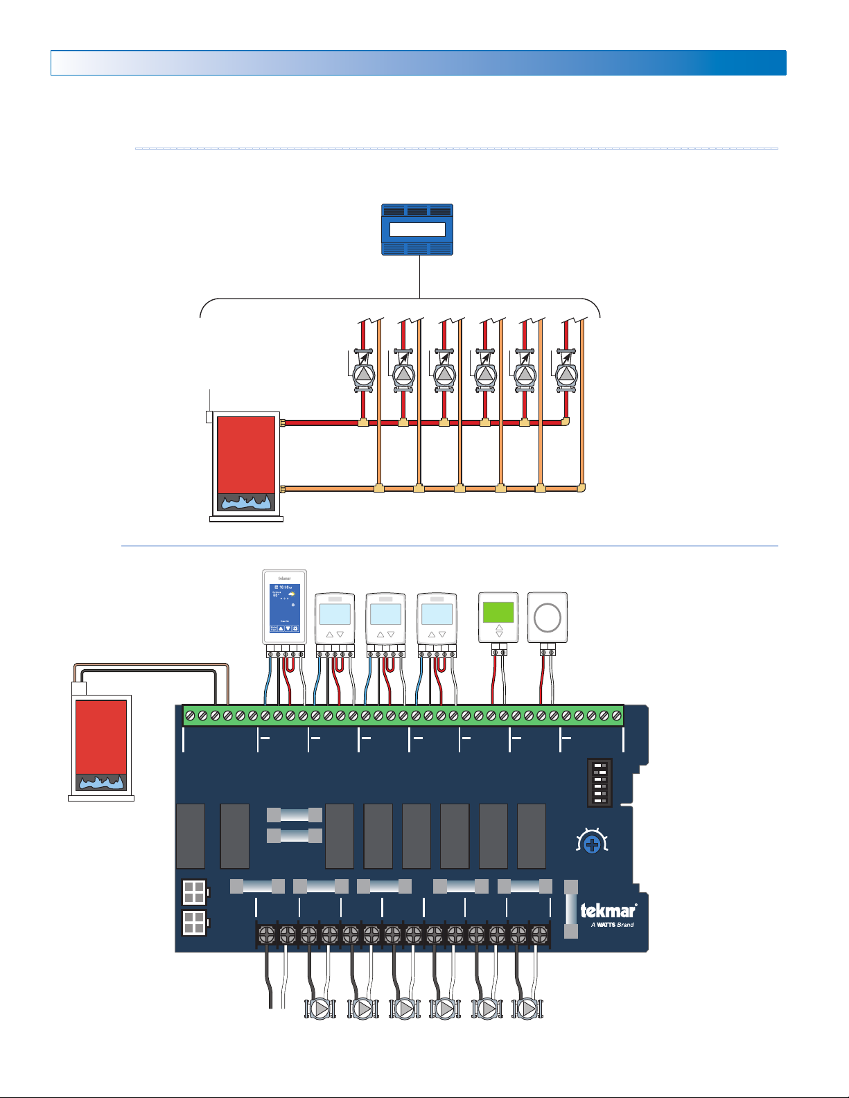
The Switching Relay 306P operates the circulators for six heating zones when the corresponding thermostat calls for heat. The
boiler is fired whenever a zone calls for heat.
Mechanical
---------------------------------------------------------------------------------------------
Legend
B1 = Boiler
P1 to P6 = Zone 1 through 6 Pump
T1 = WiFi Thermostat 561 or 562
T2 to T4 = Thermostat 518 or 519
T5 = Generic Digital Power-Stealing Thermostat
T6 = Generic Bi-Metallic Strip Thermostat
B1
Electrical
-----------------------------------------------------------------------------------------------
T1
306P
P1
P2 P3 P4 P5 P6
T2 T3 T4
T5 T6
DIP Switches
Master
T-stat 1 Priority Off
Exercising On
Post Purge On
Mod Boiler - not applicable
B1
© 2016 tekmar 306P_D - 11/16
L N
P1 P2 P3 P4 P5 P6
4 of 12
Page 5
FUSE 2
FUSE 7
FUSE 8
FUSE 3 FUSE 4 FUSE 5
FUSE 6
70 80
9060
50 100
MOD MAX %
MASTER MEMBER
OFF
OFF
OFF
4-20 mA
T-STAT 1 PRIORITY : 0N
EXERCISING : ON
POST PURGE : ON
MOD BOILER : 0-10V
RESERVED
FUSE 1
120 VAC
POWER
MOD
X X
tN4
POWER ROOM
RESPONSE
T1 T2 T3 T4 T5 T6
A
DHW C R W
BOILER T-STAT 1 T-STAT 2 T-STAT 3
PRIORIT Y
PUMP 1
PUMP 2 PUMP 3 PUMP 4 PUMP 5 PUMP 6
L
-
+
N L N L N L N L N L N L N
tN4
A
C R W
tN4
A
C R W
T-STAT 4
tN4
A
C R W
T-STAT 5
tN4
A
C R W
T-STAT 6 EX PANSION
tN4
A
C R W
tN4
A
B C D E
+T-T
DHW
-
Away C R Rh W Away C R Rh W Away C R Rh W R W R W
70
Application 306P–2
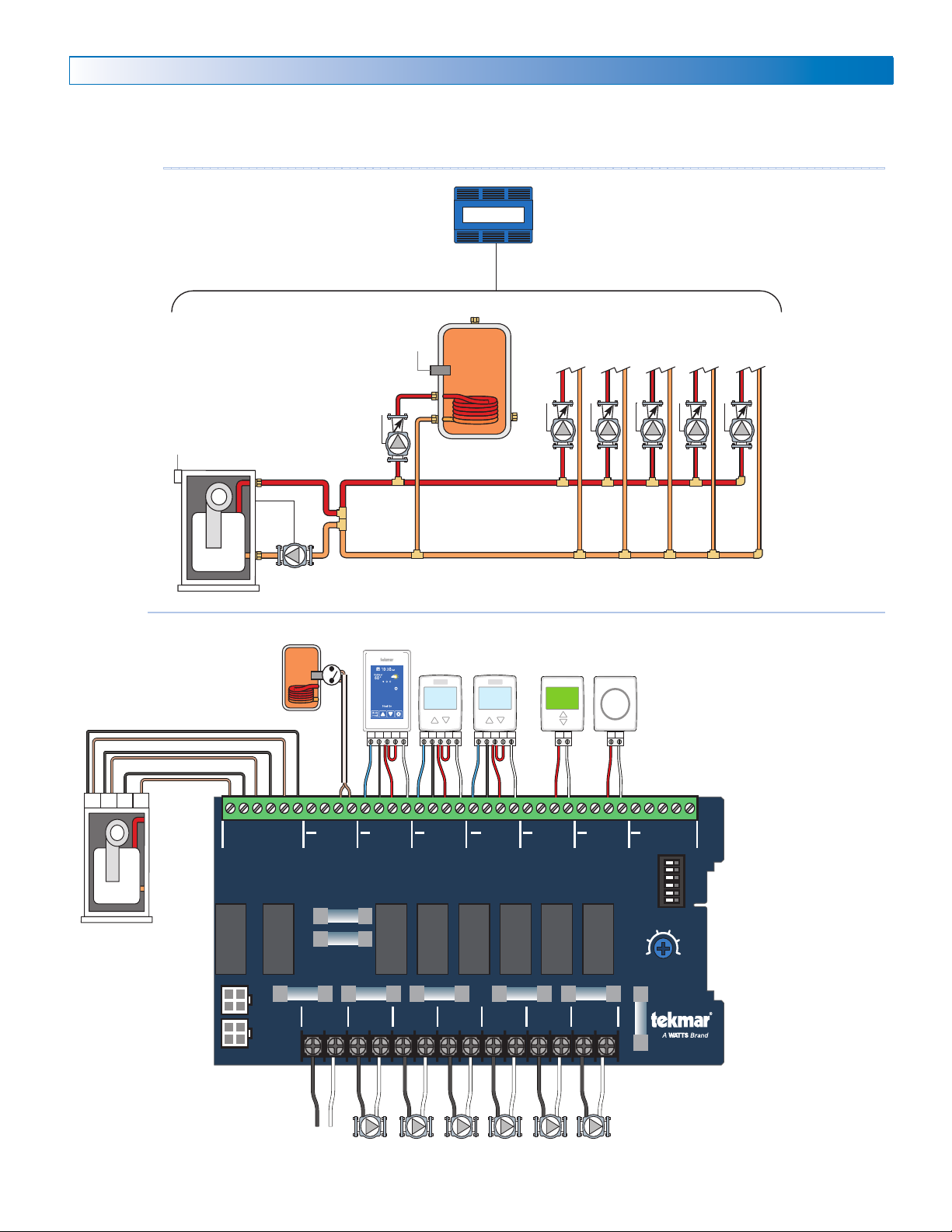
The Switching Relay 306P operates six heating zone circulators when the corresponding thermostat calls for heat. Zone 1
heats a domestic hot water tank. When priority is selected, zones 2 through 6 shut off when zone 1 is heating. The boiler is
fired when there is a call for heat.
Mechanical
---------------------------------------------------------------------------------------------
Legend
A1 = DHW Tank Aquastat
B1 = Modulating Condensing Boiler
BP = Boiler Pump
P1 = Zone 1 DHW Tank Pump
P2 to P6 = Zone 2 through 6 Pump
B1
Electrical
-----------------------------------------------------------------------------------------------
BP
A1
P1
T1
306P
A1
T2 T3 T4
T1 = WiFi Thermostat 561 or 562
T2 to T3 = Thermostat 518 or 519
T4 = Generic Digital Power-Stealing Thermostat
T5 = Generic Bi-Metallic Strip Thermostat
P2 P3 P4 P5 P6
DIP Switches
T5
Master
T-stat 1 Priority On
Exercising On
Post Purge On
Mod Boiler - depends on boiler
B1
L N
P1
P2 P3 P4 P5 P6
5 of 12
© 2016 tekmar 306P_D - 11/16
Page 6
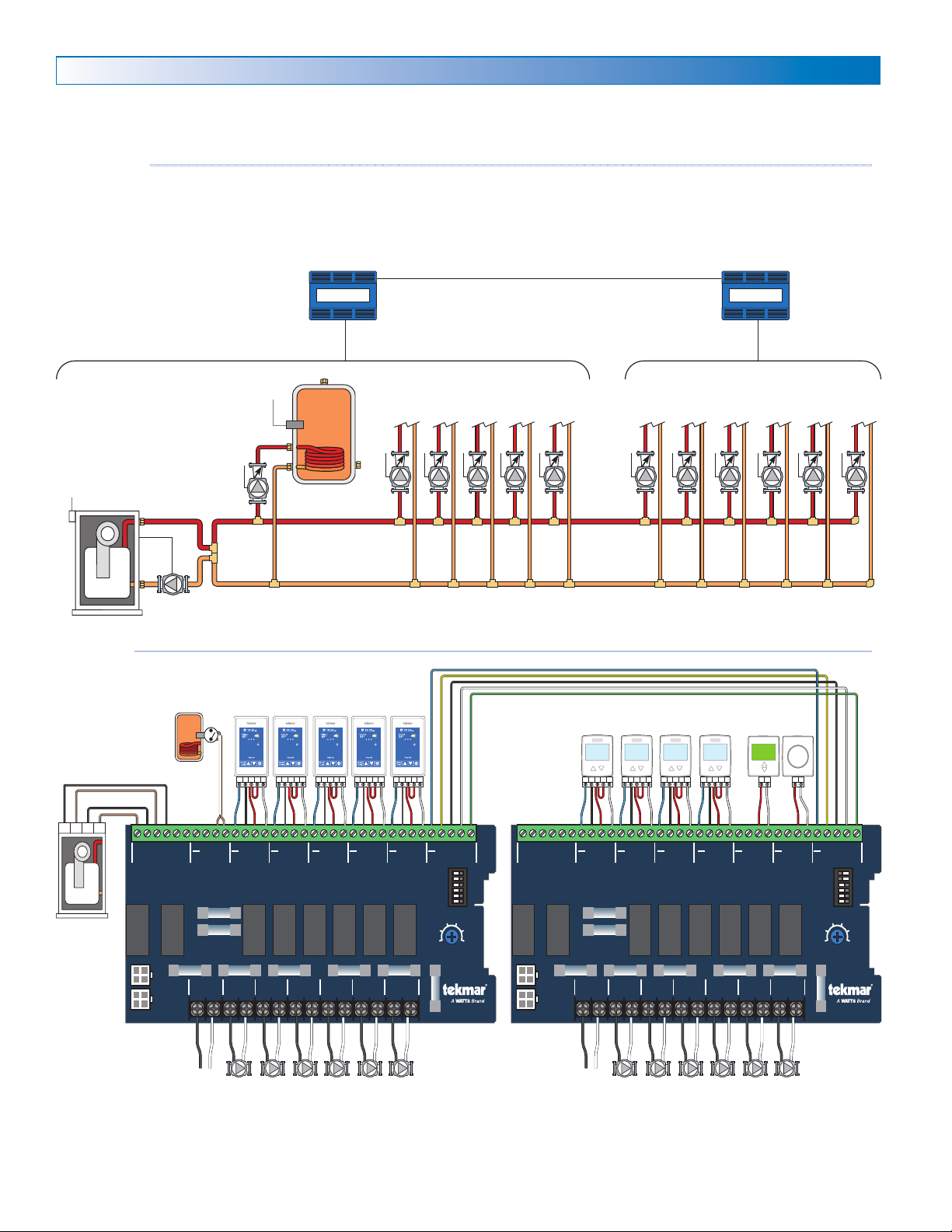
Application 306P–3
FUSE 2
FUSE 7
FUSE 8
FUSE 3 FUSE 4 FUSE 5
FUSE 6
70 80
9060
50 100
MOD MAX %
MASTER MEMBER
OFF
OFF
OFF
4-20 mA
T-STAT 1 PRIORITY : 0N
EXERCISING : ON
POST PURGE : ON
MOD BOILER : 0-10V
RESERVED
FUSE 1
120 VAC
POWER
MOD
X X
tN4
POWER ROOM
RESPONSE
T1 T2 T3 T4 T5 T6
A
DHW C R W
BOILER T-STAT 1 T-STAT 2 T-STAT 3
PRIORITY
PUMP 1
PUMP 2 PUMP 3 PUMP 4 PUMP 5 PUMP 6
L
-
+
N L N L N L N L N L N L N
tN4
A
C R W
tN4
A
C R W
T-STAT 4
tN4
A
C R W
T-STAT 5
tN4
A
C R W
T-STAT 6 EXPANSION
tN4
A
C R W
tN4
A
B C D E
FUSE 2
FUSE 7
FUSE 8
FUSE 3 FUSE 4 FUSE 5
FUSE 6
70 80
9060
50 100
MOD MAX %
MASTER MEMBER
OFF
OFF
OFF
4-20 mA
T-STAT 1 PRIORITY : 0N
EXERCISING : ON
POST PURGE : ON
MOD BOILER : 0-10V
RESERVED
FUSE 1
120 VAC
POWER
MOD
X X
tN4
POWER ROOM
RESPONSE
T1 T2 T3 T4 T5 T6
A
DHW C R W
BOILER T-STAT 1 T-STAT 2 T-STAT 3
PRIORITY
PUMP 1
PUMP 2 PUMP 3 PUMP 4 PUMP 5 PUMP 6
L
-
+
N L N L N L N L N L N L N
tN4
A
C R W
tN4
A
C R W
T-STAT 4
tN4
A
C R W
T-STAT 5
tN4
A
C R W
T-STAT 6 EXPANSION
tN4
A
C R W
tN4
A
B C D E
+TT
-
Away C R Rh W Away C R Rh W Away C R Rh W Away C R Rh W Away C R Rh W Away C R Rh WAway C R Rh WAwayC R Rh W Away C R Rh W R W R W
70 70 70 70 70
Two Switching Relay 306P operate twelve heating zone circulators. The two controls are connected together using an expansion
bus wire. The master 306P fires the boiler when any zone calls for heat. If priority is selected, zones 2 through 12 shut off when
zone 1 is calling for heat.
Mechanical
---------------------------------------------------------------------------------------------
Legend
A1 = DHW Tank Aquastat
B1 = Modulating Condensing Boiler
BP = Boiler Pump
P1 = Zone 1 DHW Tank Pump
P2 to P12 = Zone 2 through 12 Pump
B1
P1
BP
T1 to T5 = WiFi Thermostat 561 or 562
T6 to T9 = Thermostat 518 or 519
T10 = Generic Digital Power-Stealing Thermostat
T11 = Generic Bi-Metallic Strip Thermostat
306P 306P
A1
P2 P3 P4 P5 P6
Expansion
P7 P8 P9
P10
P11 P12
Electrical
-----------------------------------------------------------------------------------------------
B1
DIP Switches
Master
T-stat 1 Priority On
Exercising On
© 2016 tekmar 306P_D - 11/16
T1
A1
T2 T3 T4 T5
T6 T7 T8 T9
LLN
P1
Post Purge On
Mod Boiler - depends on boiler
P2P8P3P9P4
P5 P6
N
DIP Switches
Member
T-stat 1 Priority Off
Exercising On
P7
Post Purge On
Mod Boiler - not applicable
6 of 12
P10
T10
P11 P12
T11
Page 7

User Interface - Indicator LED
Power
• On when 115 V (ac) is applied.
•
Off when power disconnected or transformer fuse is blown.
Priority
• On when zone 1 has priority over zones 2 to 6.
RoomResponse
• On when modulating condensing boiler is operating below
maximum setting.
TM
Sequence of Operation
Zone Operation
When a thermostat calls for heat by closing the R and W
terminals:
• 115 V (ac) is applied to the corresponding circulator pump.
• The corresponding zone indicator LED is turned on.
Boiler Operation
When a thermostat calls for heat by closing the R and W
terminals:
• The boiler end switch XX is closed to fire the boiler.
•
The RoomResponseTM 0-10 V (dc) or 4-20 mA signal is sent
to a modulating-condensing boiler.
DHW Operation
Many modulating-condensing boilers have multiple temperature
call inputs. Wire the DHW end switch to input recommended
in the boiler's manual.
When a zone 1 calls for heat by closing the R and W terminals:
• The DHW end switch is closed to fire the boiler at the DHW
temperature.
• The Mod Boiler output is changed to 10 V (dc) or 20 mA.
Master / Member DIP Switch
•
Allows for unlimited expansion using additional Switching
Relays and/or Zone Valve Controls.
•
The Master Switching Relay is wired and operates the boiler.
• If using a single Switching Relay set to Master.
•
When using multiple Switching Relays and/or Zone Valve
Controls, set one control to Master and set all other controls to Member.
T-Stat 1 Priority DIP Switch
When T-Stat 1 is calling for heat by closing the R and W
terminals:
• 115 V (ac) is applied to the zone 1 circulator pump.
• Zone 1 indicator LED is turned on.
• Priority indicator LED is turned on.
• Zones 2 to 6 circulator pumps and LEDs are turned off.
• Expansion Member controls shut off their zones.
•
After 60 minutes of continuous zone 1 call for DHW heating,
zones 2 to 6 and all Expansion Member control zones are
able to turn back on. This prevents building freeze up if the
DHW tank aquastat fails in the closed position.
Exercising DIP Switch
ON: Each circulator pump is energized for 30 seconds every
72 hours.
OFF: Circulator pump exercising disabled.
Zone 1
• On when thermostat 1 calls for heat.
Zones 2 to 6
• On when the corresponding thermostat calls for heat.
• Off during priority operation.
• Off when corresponding thermostat stops calling for heat.
Post Purge DIP Switch
ON: After the last thermostat stops calling for heat, the last
circulator pump remains on for 2 minutes to purge heat from
the boiler to the zone.
OFF: Post purge disabled.
Mod Boiler DIP Switch
Select either 0-10 V (dc) or 4-20 mA signal to the modulating
condensing boiler. Consult the boiler manual to determine
the signal type. The DIP switch position does not matter if
the modulating boiler output is not used.
Fuses
• All fuses are T5A 250V slow blow.
• Fuses 1 to 6 correspond to the zone 1 to 6 circulator pump
output. If a fuse is blown, first check that the pump is not
seized and the wiring is not shorted. Then replace the fuse.
•
Fuse 7 and 8 correspond to the 24 V (ac) transformer power
supply. If a fuse is blown, first check that the thermostat
wiring is not shorted. Then replace the fuse.
Expansion Terminals
Connect the five wires of the expansion bus from the master
to the member controls.
Terminal Description
A/tN4 Away signal connecting tekmar thermostats
B
C Power common
D
E Priority signal. 0 Vdc = priority. 2 Vdc = no priority
RoomResponseTM signal from member controls
Demand signal. 0 Vdc = demand. 2 Vdc = no demand
7 of 12
© 2016 tekmar 306P_D - 11/16
Page 8

RoomResponseTM Signal
70 80
9060
50 100
MOD MAX %
The RoomResponseTM signal adjusts the temperature of a
modulating condensing boiler that accepts a 0-10 V(dc) or 4-20
mA signal input. It works by continually adjusting boiler water
temperatures to the lowest possible value to meet comfort
without wasting energy. This is done by monitoring each
thermostat's on and off time pattern and determines the ideal
water temperature for each zone. The control then chooses the
highest water temperature requirement of all the thermostats
and provides a 0-10 V (dc) or 4-20 mA signal proportional to
the boiler operating temperature. The RoomResponseTM signal
is a DOE compliant method of controlling boiler temperature
to building load. The RoomResponseTM signal is not available
to on/off boilers.
Benefits of the RoomResponseTM signal include:
• Increase in boiler efficiency
• Reduction in room temperature swing
• Reduction in expansion noises from heating pipes
Mod Max % Dial
The upper limit of the 0-10 V (dc) or 4 -20 mA signal to the
modulating condensing boiler can be set using the Mod Max
% Dial.
This sets the upper temperature limit for the boiler.
Mod Max % dial set to 100% in the illustration.
The dial is only applicable to controls set as the Master.
Mod Max % Max Voltage Max mA
50 5 12
60 6 13.6
70 7 15.2
80 8 16.8
90 9 18.4
100 10 20
Setting the Max Mod % Dial
Required Adapter
Boiler Make/Model
Aerco AM series Not required 0-10 V 50% 65% 80% 100%
Bosch Greenstar ICM Module 0-10 V 55% 70% 80% 100%
Buderus GB142, GB162 EM10 Module 0-10 V 50% 60% 75% 90%
Burnham® Alpine
Camus® Modulating Micoflame
HTP Elite Not required 0-10 V 50% 65% 80% 90%
IBC VFC and SL series*
Laars® Mascot LX Not required 0-10 V 55% 70% 85% 100%
Laars® Mascot FT Not required 0-10 V 50% 65% 80% 100%
Lochinvar® Knight
Lochinvar
NTI Trinity Fire Tube and LX Not required 4-20 mA 55% 65% 75% 90%
Peerless PureFire PFA-1 Adapter 0-10 V 55% 65% 75% 90%
Raypak Xfyre, Xtherm, MVB, XPakFT Not required 0-10 V 55% 65% 80% 90%
Riverside HeatStation*
Viessmann 100-W, WB1B
Viessmann 200-W, B2HB and 300 CU3A Not required 0-10 V 50% 60% 70% 80%
Weil-McLain
* Requires changes to boiler's settings
®
™
*
™
FTXL*
®
Evergreen*
®
(Supplied by boiler
manufacturer)
Not required 4-20 mA 50% 70% 85% 100%
Not required 0-10 V 50% 60% 70% 85%
Not required 0-10 V 65% 75% 85% 100%
Not required 0-10 V 55% 70% 85% 100%
Not required 0-10 V 55% 70% 85% 100%
Not required 0-10 V 50% 65% 85% 100%
OpenTherm
Module
Not required 0-10 V 50% 70% 85% 100%
0-10 V (dc) /
4-20 mA
DIP Switch
0-10 V 55% 70% 85% 100%
Mod Max % Dial for Boiler Design Temperature
120°F 140°F 160°F 180°F
© 2016 tekmar 306P_D - 11/16
8 of 12
Page 9
+
–
9+10
–
+
–
22+23
–
+
–
5+6
–
+
–
16–17
+
+
–
2U1
+
–
X
X
T
T
–
+
1 2 9 10
Aerco AM Series
+
–
X
X
T
T
–
+
1 2 9 10
+
–
X
X
T
T
–
+
5 6 11 12
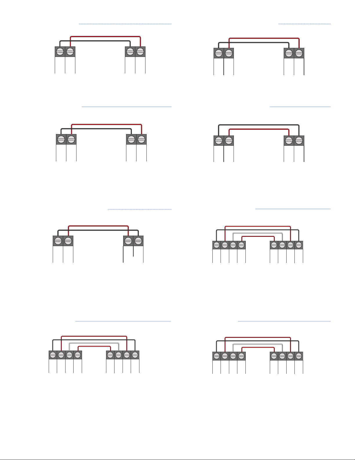
--------------------------------
Camus Modulating MicoFlame
------------------
306P
Aerco AM
• No changes to the boiler are required.
Bosch Greenstar
-------------------------------
306P
Bosch ICM
• Install the Bosch ICM as per the directions.
•
Set ICM jumper to the left position to enable system supply
water temperature (VT) mode.
Buderus GB142 and GB162
----------------------
306P
Camus
Micoflame
• Change control to mode 6 in the control parameters.
Heat Transfer Products Elite
306P
---------------------
HTP
Elite
• Move jumper on connection board from A to B.
• Set function 17 to temperature.
IBC VFC and SL Series
--------------------------
306P
Buderus
EM10 Module
• Install the Buderus EM10 module as per the directions.
• Do NOT install the jumper between U terminals 1 and 3 on
the EM10 module.
Burnham Alpine
---------------------------------
306P
Burnham
Alpine
• Change Parameter 9 Remote 4-20 mA to Setpoint Source.
•
Change "Energy Management" setting "Central Heat
Modulation Source" to 4-20 mA.
•
Change "Energy Management" setting "Central Heat 4-20
mA Setup, 4 mA Water Temperature" to 80°F (26.5°C).
306P
IBC V10
Control
On the V10 controller:
• Set Load 1 to External Control
• Change "Max Control @ 9.5 Vdc" to 190°F (88°C)
• Change "Min Control @ 2.1 Vdc" to 32°F (0°C)
Laars Mascot LX
•
Change Installer Parameter 25 "0-10V to Power" to Disabled.
--------------------------------
306P
Laars
Mascot LX
• Change Installer Parameter 26 "0-10V to outlet setpoint" to
Disabled.
9 of 12
© 2016 tekmar 306P_D - 11/16
Page 10
+
–
X
X
W
R
–
+
19 20 33 34
+
–
X
X
W
R
–
+
21 22 35 36
+
–
X
X
CH1
R
+
–
3 5 11 12
+
–
X
X
CH1
R
–
+
3 5 4 5
+–
–
+
8
EMS
9
+
–
16–17
+
+
–
15+16
–
2–8+1 2 1 2
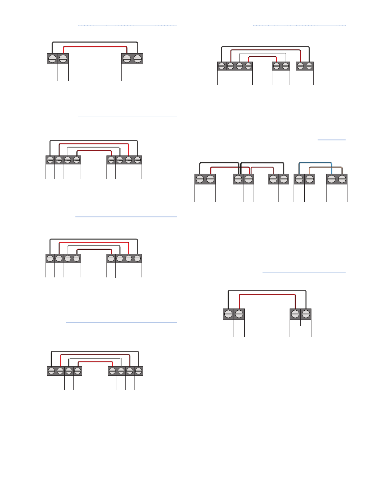
Laars Mascot FT
--------------------------------
NTI Trinity FireTube
------------------------------
306P
Laars
Mascot FT
• No changes to the boiler are required.
Lochinvar Knight
306P
•
Set BMS Type to Setpoint. This is the factory default setting.
Lochinvar FTXL
--------------------------------
Lochinvar
Knight
---------------------------------
306P
24Vac I/O
NTI Trinity Fire Tube
Sensor I/O
• Enter boiler password.
• Set Parameter "Setpoint source" to 4-20mA
Peerless Pinnacle PF-200, 210, 300, 399
306P J5 J8 J18
Peerless
Pinnacle
Terminal Strip
Peerless
PFA-1 Interface
Adapter
---------
Peerless
Pinnacle
Control Board
• Install the Peerless PFA-1 Interface Adapter
•
On the boiler display, change Central Heating Mode to 4 for
0-10 VDC Input to Modulate Setpoint
306P
Lochinvar
FTXL
• Set BMS parameter to ACTIVE.
• Set BMS Type to SETPOINT.
NTI Trinity LX
------------------------------------
306P
NTI Trinity LX
• Enter boiler password.
• Set Parameter "Setpoint source" to 4-20mA
Riverside HeatStation
306P
---------------------------
• Set boiler PIM DIP switch 2 to Off.
• Set boiler PIM DIP switch 5 to On.
• Set boiler PIM DIP switch 6 to Off.
• Set APP parameter to EMS
• Set SIGNAL parameter to 0-10Vdc
• Set SETP LO to 70°F
• Set SETP HI to 180°F
Riverside
HeatStation
© 2016 tekmar 306P_D - 11/16
10 of 12
Page 11
+
–
X
X
–
+
13 14 17 18
+– XX
–
+
T
T
8 9 9 10
+
–
1–4
+
+
–
1–2
+
+
–
5+6
–
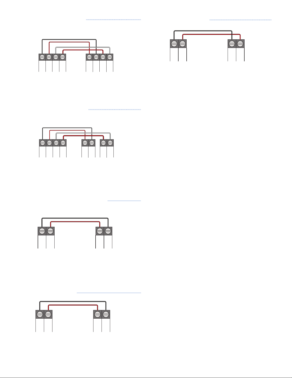
Raypak MVB and XTherm
-----------------------
Weil-McLain Evergreen
--------------------------
306P
Raypak MVB or
XTherm
• Set boiler PIM DIP switch 2 to Down.
• Set boiler PIM DIP switch 5 to Up.
Raypak XFyre and XPakFT
306P
----------------------
J2 J1
Raypak XFyre or
XPakFT
• Set boiler PIM DIP switch 2 to Down.
• Set boiler PIM DIP switch 5 to Up.
Viessmann Vitodens 100-W, WB1B
--------------
306P
Weil-McLain
Evergreen P15
• Use Local Priority 1 for DHW tank heating.
• Use Local Priority 2 for the RoomResponseTM signal.
• Set Local Priority 2 Supply Min to 60°F.
• Set Local Priority 2 Supply Max to 180°F.
• Set Local Priority 2 Volts For Min to 2 V.
• Set Local Priority 2 Volts For Max to 10 V.
306P
Install the OpenTherm Module as per the boiler manufac-
•
Viessmann
OpenTherm Module
turer's instructions.
Viessmann Vitodens 200-W, B2HP and
Vitocrossal 300 CU3A
306P
•
Connect to the Viessmann Extension Module EA1 Plug 0-10V.
---------------------------
Viessmann
Extension Module EA1
Plug 0-10V
11 of 12
© 2016 tekmar 306P_D - 11/16
Page 12

Technical Data
Switching Relay 306P Six Zones with Priority
Literature 306P_C, 306P_D, 306_J
Control Microprocessor control. This is not a safety (limit) control.
Packaged weight 5.0 lb. (2250 g)
Dimensions 8-3/16" H x 10-11/16" W x 2-3/8" D (208 x 271 x 60 mm)
Enclosure Cover: ABS plastic, Base: galvanized steel, NEMA type 1
Approvals
Ambient conditions 32 to 122°F (0 to 50°C), ≤ 90% RH non-condensing
Power supply 115 V (ac) ±10%, 60 Hz, 20 A
Transformer 40 VA, expandable to 80 VA with additional transformer M3069 (sold separately)
Fuses T5A 250 V slow blow, two spare fuses included
Pump relays 230V (ac), 5 A, 1/3 hp
Boiler XX end switch 24 V (ac), 5 A
DHW end switch 24 V (ac), 5 A
Mod boiler output 0-10 V (dc) 500 Ω min impedance / 4-20 mA 1 kΩ max impedance
CSA C US
Limited Warranty and Product Return Procedure
Limited Warranty The liability of tekmar under this warranty is limited. The
Purchaser, by taking receipt of any tekmar product (“Product”), acknowledges th e terms of the Limited Warranty in effect at the time of such Product
sale and acknowledges that it has read and understands same.
The tekmar Limited Warranty to the Purchaser on the Products sold hereunder
is a manufacturer’s pass-through warranty which the Purchaser is authorized to
pass through to its customers. Under the Limited Warranty, each tekmar Product is warranted against defects in workmanship and materials if the Product
is installed and used in compliance with tekmar’s instructions, ordinary wear
and tear excepted. The pass-through warranty period is for a period of twenty-four (24) months from the production date if the Product is not installed during
that period, or twelve (12) months from the documented date of installation if
installed within twenty-four (24) months from the production date.
The liabilit y of tekmar under the Limited Warranty shall be limited to, at tek mar’s
sole discretion: the cost of parts and labor provided by tekmar to repair defects in
materials and / or workmanship of the defective produc t; or to the exchange of the
defective pro duct for a warranty replacement product; or to the granting of credit
limited to the original cost of the defective product, and such repair, exchange or
credit shall be the sole remedy available from tekmar, and, without limiting the
foregoing in any way, tekmar is not responsible, in contract, tort or strict product liability, for any other losses, c osts, expenses, inconveniences, or damages,
whether direct, indirect, special, secondar y, incidental or consequential, arising
from ownership or use of the product, or from defects in workmanship or materials,
including any liability for fundamental breach of contract.
The pass-through Limited Warranty applies only to those defective Products
returned to tekmar during the warranty period. This Limited Warranty does not
cover the cost of the parts or labor to remove or transport the defective Product, or
to reinstall the repaired or replacement Product, all such costs and expenses being
subjec t to Purchaser’s agreement and warranty with its customers.
Any representations or warranties about the Products made by Purchaser to its customers which are different from or in excess of the tekmar Limited Warranty are the
Purchaser’s sole responsibility and obligation. Purchaser shall indemnify and hold
tekmar harmless from and against any and all claims, liabilities and damages of any
kind or nature which arise out of or are related to any such representations or warranties by Purchaser to its customers.
The pass-through Limited Warranty does not apply if the returned Product has been
damaged by negligence by persons other than tekmar, accident, fire, Act of God,
abuse or misuse; or has been damaged by modifications, alterations or attachments
made subsequent to purchase which have not been authorized by tekmar; or if the
Product was not installed in compliance with tekmar’s instructions and / or the local
codes and ordinances; or if due to defective installation of the Product; or if the Product was not used in compliance with tekmar’s instructions.
THIS WARRANTY IS IN LIEU OF ALL OTHER WARRANTIES, EXPRESS OR
IMPLIED, WHICH THE GOVERNING LAW ALLOWS PARTIES TO CONTRACTUALLY EXCLUDE, INCLUDING, WITHOUT LIMITATION, IMPLIED WARRANTIES
OF MERCHANTABILITY AND FITNESS FOR A PARTICULAR PURPOSE, DURABILITY OR DESCRIPTION OF THE PRODUCT, ITS NON-INFRINGEMENT OF
ANY RELEVANT PATENTS OR TRADEMARKS, AND ITS COMPLIANCE WITH
OR NON-VIOLATION OF ANY APPLICABLE ENVIRONMENTAL, HEALTH OR
SAFETY LEGISLATION; THE TERM OF ANY OTHER WARRANTY NOT HEREBY
CONTRACTUALLY EXCLUDED IS LIMITED SUCH THAT IT SHALL NOT EXTEND
BEYOND TWENTY-FOUR (24) MONTHS FROM THE PRODUCTION DATE, TO
THE EXTENT THAT SUCH LIMITATION IS ALLOWED BY THE GOVERNING LAW.
Product Warranty Return Proc edure All Products that are believed to have
defects in workmanship or materials must be returned, together with a writ ten
description of the defect, to the tekmar Representative assigned to the territor y in
which such Product is located. If tekmar receives an inquiry from someone other
than a tekmar Representative, including an inquir y from Purchaser (if not a tekmar
Representative) or Purchaser’s customers, regarding a potential warranty claim,
tekmar’s sole obligation shall be to provide the address and other contact information regarding the appropriate Representative.
WAR NING: This product conta ins chemi cals known to the State of
California to cause cancer and birth defects or other reproductive harm.
For more information: Watts.com/prop65
All speci cations are subject to change without notice
Tel: (250) 545-7749 • Fax: (250) 984-0815
tekmarControls.com
306P_D - 11/16 12 of 12 © 2016 tekmar
 Loading...