

Page 1
Quick Setup Guide
tekmarNet® Thermostat 552
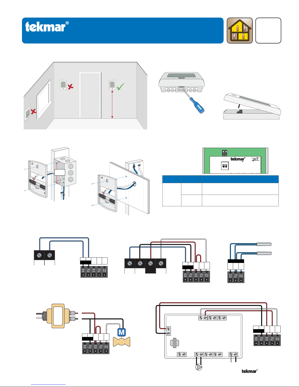
Location1. Remove Mounting Base2.
Interior
Wall
5 feet
1.5 m
Exterior
Wall
Zoning
Q 552
11/11
Replaces: 08/11
Install Mounting Base3.
Thermostat
Base
Wiring5.
tN2 tN2
To tN2 device
Stud
3 1/4”
(83 mm)
tekmarNet®2
tN4
tN2
Thermostat
C
R
tN2
Switch
Box
Thermostat
Base
Rh W1
Stud
Wall
tekmarNet®4
tN4 C W
R
To tN4 device
Switch Settings4.
Thermostat
Switch
1
Back of
Position
ON
OFF
C
tN4
R
tN2
tN2
Rh W1
Thermostat
123
1051-03
1051-03
Switch
Settings
ON
Lock
ON
Setback
1
ck
itch Settings:
lock
tekmarNet
tNt 552
None
Scene
One Stage Heat
Thermostat 552
One Stage Heat
2
www.tekmarcontrols.com
ed
ol Master 1
Mmm YYYY
/
Lot # 12345
/
Action
LOCK Access level adjustment is not
available.
UNLOCK Access level adjustment is
available.
Sensors
No Power
S1 S2
Com
Thermostat
Standalone - Zone Valve
L
N
24 V (ac)
Tran sfo r me r
R
C
C
tN4
R
tN2
tN2
Rh W1
Thermostat
1 of 2 © 2011 Q 552 - 11/11
Valve
Standalone - Switching Relay
W
R
W
R
(T)(T)
(T)(T)
24 V
Com
Switching Relay
W
R
(T)(T)
Zone 1
Zone 2 Zone 3
HNXX HNHN NL
Pump
NL
C
tN4
R
tN2
tN2
Rh W1
Thermostat
Page 2
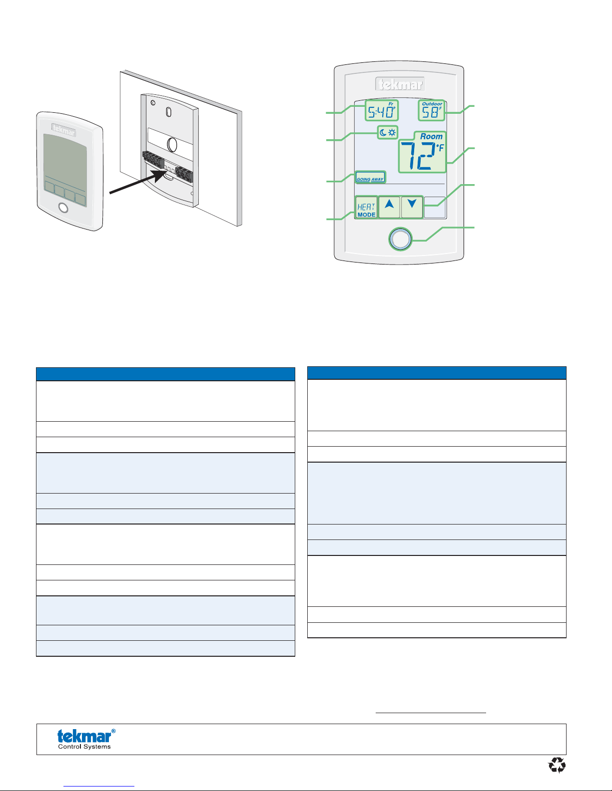
Install Thermostat6.
Thermostat
Base
User Interface7.
Thermostat
Front
Push
Adjust
the Time.
Adjust the
Schedule.
Away Key.
Turn the
Heat on
or Off.
Home
Button
Display the
Floor or Outdoor
temperature.
Room
Temperature.
Adjust the Temperature.
Home Button.
Return to the ‘Home’
Screen from any menu.
Press and hold for 3
seconds to access the
programming menus.
Critical Settings8.
The following settings are essential to the successful operation of the system.
Step 1: Set switch setting #1 and tekmarNet® system control located in the mechanical room to Unlock to change Access
level to Installer. Return to Lock setting once installation has been completed.
Step 2: Press and hold “Home” button for 3 seconds to enter programming menus.
Step 3: Touch NEXT to locate the Setup Menu and touch ENTER.
Setup Menu Settings
SENSOR 1
Select to the type of sensor connected to auxiliary sensor
input 1.
Range: OFF, ROOM, FLOR (floor), OUT (outdoor)
Default: OFF
SENSOR 2
Select to the type of sensor connected to auxiliary sensor
input 2.
Range: OFF, ROOM, FLOR (floor)
Default: OFF
ROOM SENSOR
Select whether the built-in room temperature sensor is on
or off.
Range: OFF or ON
Default: ON
W1 TERMINAL UNIT
Select the terminal unit type of the first stage of heat W1.
Range: CTRL, HRF1, HRF2, CONV, COIL, OTHR
Default: CTRL
Setup Menu Settings
W1 PUMP
Select whether the boiler system pump or mix system
pump on a tekmarNet® system control should operate
while the first stage of heat W1 is operating.
Range: OFF or ON
Default: ON
W1 THERMAL MOTOR
Select whether the first stage of heat W1 operates a
thermally actuated zone valve (wax actuator). When set
to ON, there is a 3 minute delay before operating the
pump and any heat sources.
Range: OFF or ON
Default: OFF
W CYCLES PER HOUR
Select the number of heating cycles per hour. Only
available when the thermostat is not connected to a
tekmarNet® System Control.
Range: SYNC, AUTO, 2 to 12
Default: SYNC
For a full list of settings and operational details, please refer to the thermostat Installation and Operation Manual (D552)
included with compatible tekmarNet® controls or download the brochure from www.tekmarcontrols.com
tekmar Control Systems Ltd., Canada, tekmar Control Systems, Inc., U.S.A.
Vernon, B.C. Canada V1B 3K4, 250-545 -7749, Fax. 250- 545 -0650 Web Site: www.tekmarcontrols.com
Product design, soft ware and literature are Copyright © 2011 by:
tekmar Control Systems Ltd. and tekmar Control Systems, Inc.
2 of 2
Head Offi ce: 5100 Silver Star Road,
All specifications are subject to change without notice.
Printed in Canada. Q 552 - 11/11.
 Loading...