

Page 1
Quick Setup Guide
tekmarNet®2 House Control 402
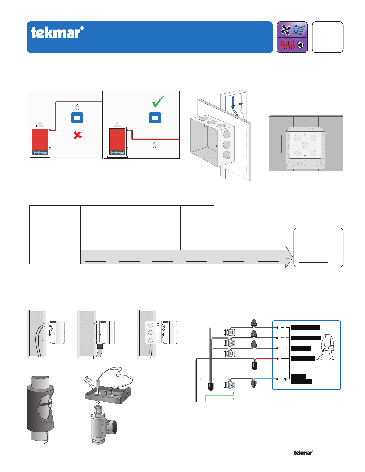
Location1. Install Junction Box2.
HVAC Systems
Q 402
09/10
Replaces: 06/09
Size Transformer3.
Zone
Thermostat Load
Zone Valve Load
Total Zone Load
402
402
1234
Floating
Action (VA)
+ ++++
OR
Control
Load (VA)
2
Transformer
must exceed:
VA
Install Sensors4.
Outdoor Sensors
Sensor with rear
entry wiring
Pipe Sensors
1 of 4 © 2010 Q 402 - 09/10
Retaining Clip
Sensor with bottom
entry wiring
Universal
Sensor 082
Sensor Well
Sensor mounted
onto 2" x 4"
electrical box
Line Voltage Wiring5.
G
L
N
115 V (ac)
Mix
Boil
DHW
(black)
(black)
(black)
(red)
L
(blue)
Variable
N
Speed
to pump grounds
Back of House Control 402
Mix System Pump
Boil System Pump
DHW Pump
Pump Power L
Variable
Speed Pump
Strip wires
1/2 inch (13 mm).
Installed wires are
not removable.
12-18 AWG
Page 2
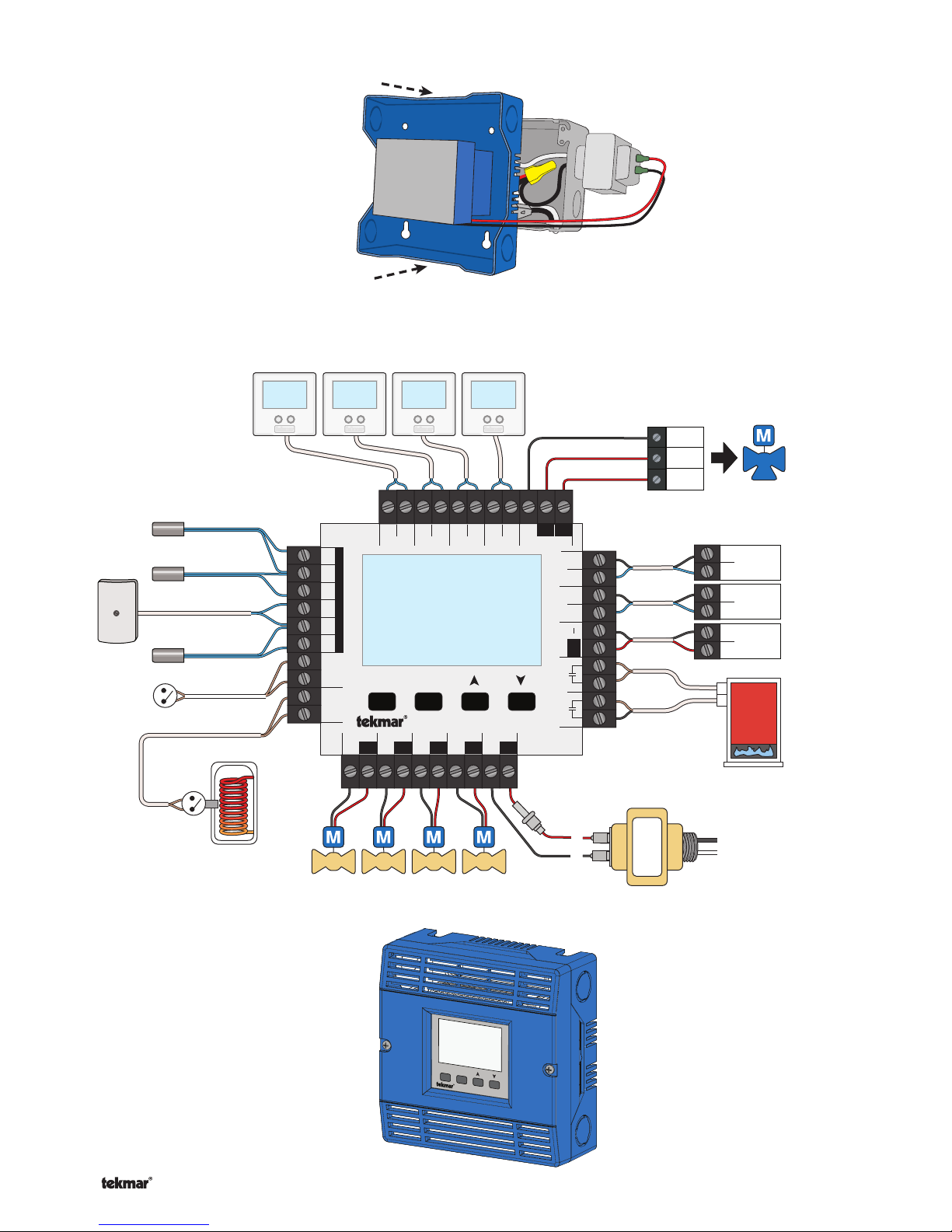
Install Enclosure6.
R
C
L
N
Com
Open
Close
Expansion
tN4 Boil
CtN4
Modulating
Boiler
—+
Expansion
tN4 Mix
CtN4
2
1
WC
WC
Menu
House Control 402
Item
+
Mix ComBoil Out DHW
VlvC VlvC VlvC
Zone 3Zone 1 Zone 2 Zone 4
Made in Canada
VlvC
Com
Zone 1
H8007B
Zone 2 Zone 3 Zone 4
tN2 tN2 tN2 tN2 tN2 tN2 tN2 tN2
C
Floating Action
ClsOpn
Sensors - No Power
Call Call
tN4 tN4CC
Mod dc/mA Boil Exp. Mix Exp.
Setpoint DHW
Use at least 167°F
(75°C) conductors
RC
Input Power
Stage 2Stage 1
Low Voltage Wiring7.
Outdoor
Sensor
070
Mix Supply
Sensor 082
Boiler Supply
Sensor 082
DHW Tank
Sensor 082
tekmarNet
®
2 Thermostats
24 V (ac) Floating
Action Actuator
®
tekmarNet
4
Expansion to
Wiring Centers,
Timers, or
User Switch
DHW Call
from DHW
Tank Aquastat
(optional)
Install Cover 8.
Setpoint Call
Zone Valves
Menu
Item
House Control 402
24 V (ac) Transformer 009
One or Two Stage
Boiler T-T
© 2010 Q 402 - 09/10 2 of 4
Page 3
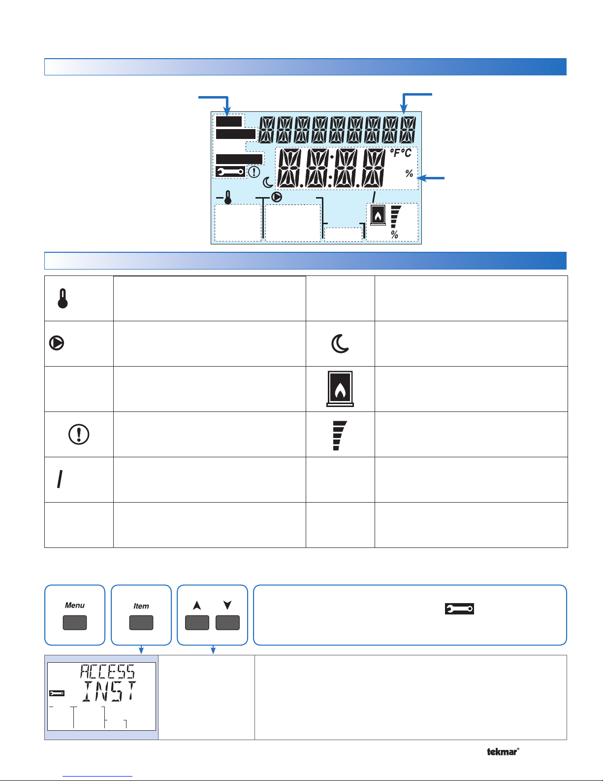
User Interface9.
Display
Symbols
Calls
Pumps
Menu Field
Displays the
current menu
VIEW
ADJUST
Status Fields
Displays the current
status of the control’s
inputs, outputs and
operation. Most symbols
in the status field are
only visible when the
VIEW Menu is selected
CALLS
Displays any call for heat the control is
receiving.
PUMPS
Displays any pump currently operating.
MONITOR
MAXMIN
Calls
Boil Exp
Mix Exp
DHW Setp
Pumps WWSD Saving
Boil System
Mix System Zones
DHW Var 1 2 3 4
°F°C
minhr
sec%
Item Field
Displays the name
of the selected item
min
sec
PM
hr
AM
Number Field
Displays the
current value of
the selected item
Cls
Opn
1 2
Mix
°F, °C, %, HOURS, MINUTES, SECOND
Units of measurement for current number.
UNOCCUPIED
Indicates that a User Switch or Timer has
put the system into UnOccupied.
Zones
1 2 3 4
Saving
WWSD
Access Level10.
ZONES
Displays if an on-board zone is operating.
WARNING
Displays if an error exists on the system.
ENERGY SAVING INDICATOR
Displays when the system is saving
energy. See the Saving Indicator section.
WWSD
Displays when the system is in Warm
Weather Shut Down.
Press menu button until the Toolbox Menu is displayed. Press
item button to locate the access level setting.
Cls
Opn
MAXMIN
BOILER
Indicates that the boiler should be
heating.
DEVICE OUTPUT SCALE
Displays output of the mixing valve or
injection pump.
CLOSE / OPEN
Displays whether the mixing valve motor
is opening or closing.
MIN / MAX
Displays when an operating temperature
reaches a minimum or maximum value.
INST (Installer)
or USER
Default = INST
ACCESS LEVEL
Selects the Access Level of the control, which determines the Menu items
available. USER provides the most limited level of access and shows
the fewest possible items.
When set to USER, all thermostats are locked and the number of
thermostat settings available are reduced.
3 of 4 © 2010 Q 402 - 09/10
Page 4
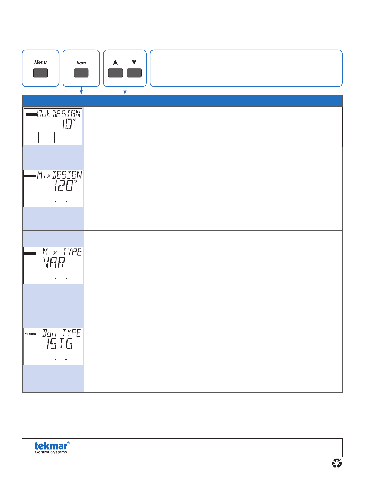
Critical Settings11.
Press menu button until the Adjust Menu is displayed. Press item
button to locate the desired setting.
Item Field Range Access Description Set to
ADJUST
ADJUST
ADJUST
-60 to 45°F
(-51.0 to 7.0°C)
Default = 10°F
(-12.0°C)
70 to 180°F
(21.0 to 82.0°C)
Default = 120°F
(49.0°C)
4-20 mA,
0-10 V (dc)
FLOT,
VAR
Default = VAR
Installer
Installer
Installer
OUTDOOR DESIGN
Typically set to the temperature of the coldest day of
the year. The outdoor air temperature used in the boiler
and mixing heating curves that determine the boiler
target and the mix target temperatures.
MIX DESIGN
The supply water temperature required for the mix
zones to heat the building on the typical coldest day
of the year. Recommendations:
High mass radiant floor = 120°F (50°C)
Low mass radiant floor = 140°F (60°C)
Fancoil or air handling unit = 190°F (90°C)
Copper fin-tube convector = 180°F (80°C)
Radiators = 160°F (70°C)
Low profile baseboard = 150°F (65°C)
MIX TYPE
Select the type of mixing device.
VAR = Variable speed injection pump
FLOT = Floating action motor for mixing valves
0-10 = 0 -10 V (dc) analog signal for mixing valves
4-20 = 4-20 mA analog signal for mixing valves
Note: 0-10 and 4-20 are only available when Boiler
Type = 1 Stage or 2 Stage.
EMS2,
EMS1,
4-20
0-10,
2STG,
1STG
Default = 1STG
tekmar Control Systems Ltd., Canada, tekmar Control Systems, Inc., U.S.A.
Vernon, B.C. Canada V1B 3K4, 250-545-7749, Fax. 250-545-0650 Web Site: www.tekmarcontrols.com
Product design, software and literature are Copyright © 2010 by:
tekmar Control Systems Ltd. and tekmar Control Systems, Inc.
Installer
BOILER TYPE
The type of boiler connected to the control.
1STG = single one-stage on-off boiler
2STG = single two-stage on-off boiler
0-10 = 0-10 V (dc) modulating boiler
4-20 = 4-20 mA modulating boiler
EMS1 = tekmar boiler staging controls
EMS2 = Viessmann modulating boilers with
OpenTherm
Note: Only 1STG and 2STG are available when the
Mix Type is set to 0-10 V (dc) or 4-20 mA.
Head Offi ce: 5100 Silver Star Road,
4 of 4
All specifications are subject to change without notice.
Printed in Canada. Q 402 - 09/10.
 Loading...