

Page 1

USERS’
MANUAL
LPF
AUTOMATIC FILTERS, INC.
2672 S. LA CIENEGA BLVD.
LOS ANGELES, CA 90034
310 839 2828 800 336 1942
FAX 310 839 6878
www.Tekleen.com
Tekleen
Page 2

Table of Contents
SECTION I INTRODUCTION
1.1 Description 1
1.2 Theory of Operation 1
1.3 Recommended Applications 1
1.4 Design Features 2
1.5 Filter Specifications Chart 3
1.6 Measurement Conversion Table 3
SECTION II INSTALLATION AND HOOK-UP
2.1 Mechanical Hook-Up and Orientation 4
2.2 Plumbing Hook-Up 4
2.3 GB6, DP Gauge, and Electric Ball Valve Connection 5
SECTION III OPERATION AND ADJUSTMENTS
3.1 Start-up 6
3.2 Backflush Requirements 7
SECTION IV MAINTENANCE
4.1 Filter Cleaning 8
4.2 Dirt Collector Replacement 8
4.3 Piston Removal/Replacement 8
4.4 Periodic Inspection 9
SECTION V TROUBLESHOOTING GUIDE
5.1 Excessive Pressure Drop Through Filter Without Flushing 9
5.2 Frequent Continuous Flushing While Filling Main Pipeline 10
5.3 Frequent Continuous Flushing During Normal Operation 10
5.4 Screen Will Not Clean Properly 11
SECTION VI SPARE PARTS
6.1 Recommended Spare Parts 12
6.2 Spare Parts List 12
APPENDICES
Appendix I Special Construction and Features 13
Appendix II System with Discharge to Atmosphere 14
Appendix III Piston 14
ILLUSTRATIONS
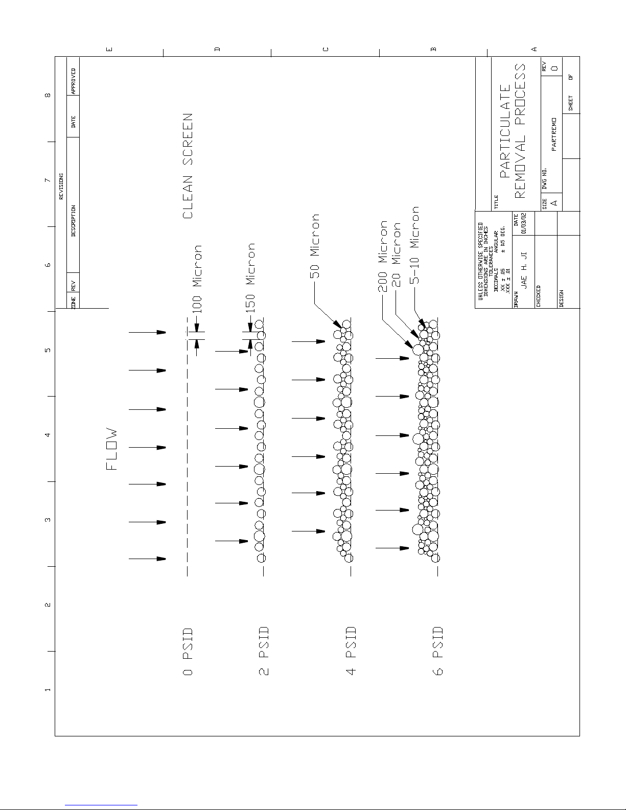
Particle Removal Process 15
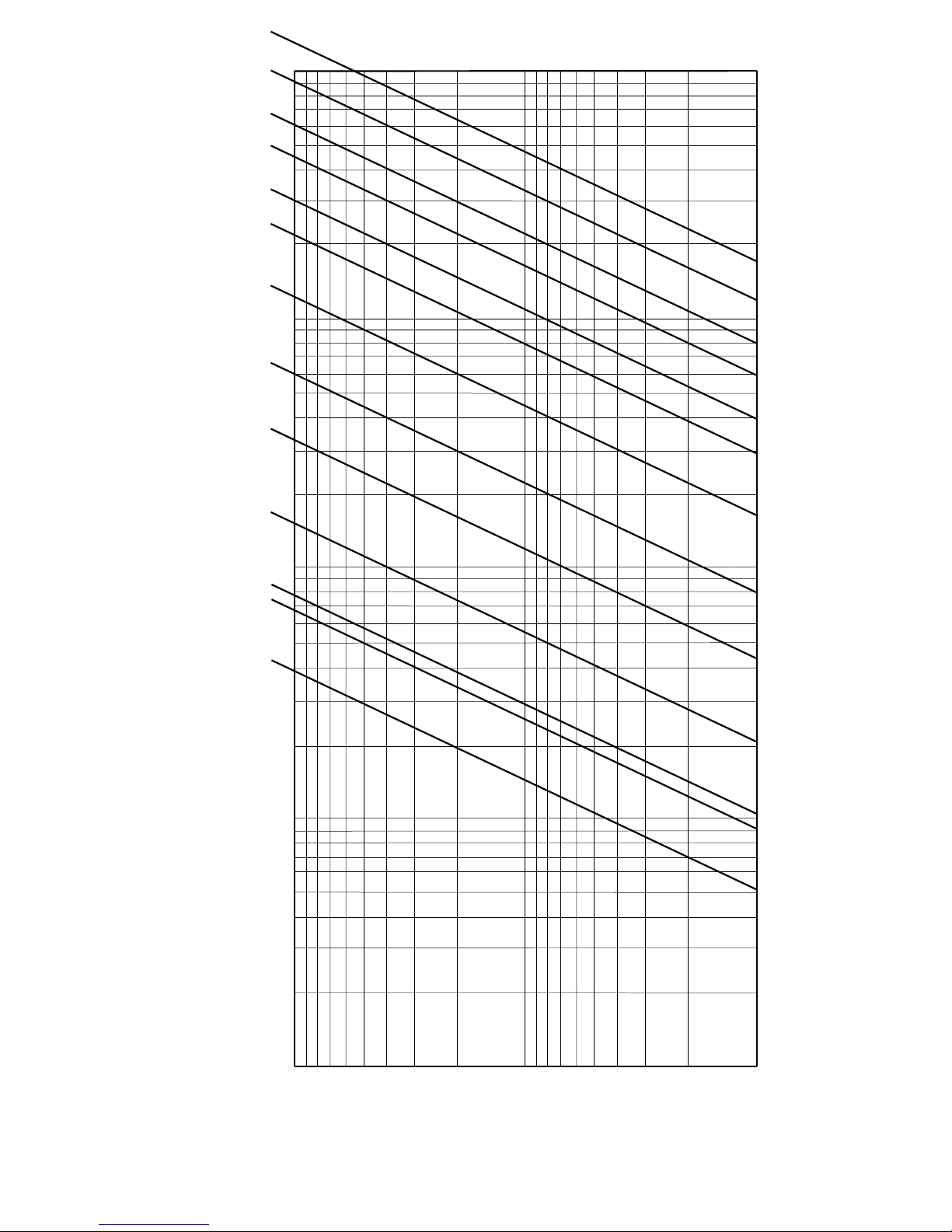
Pressure Drop Chart 16
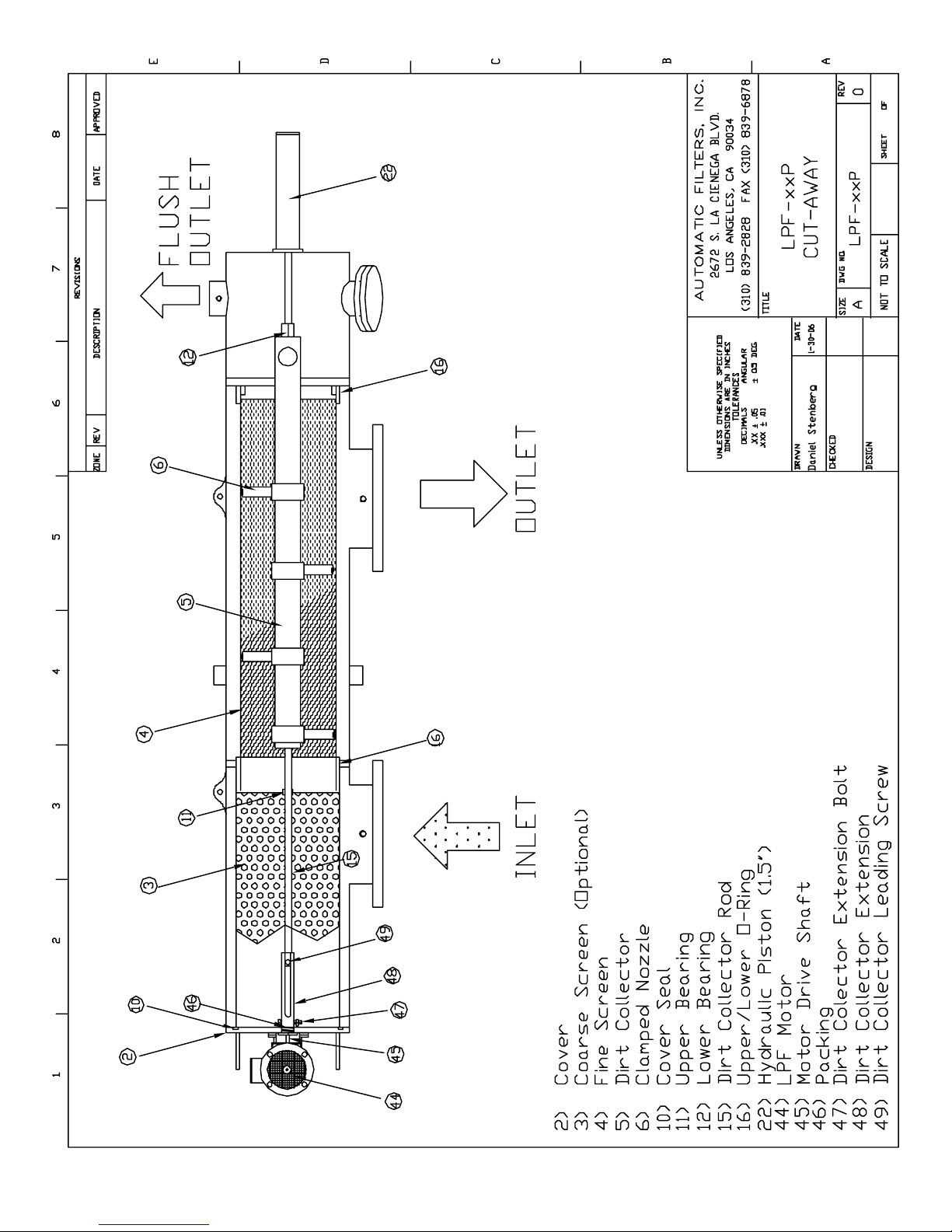
LPF Cutaway 17
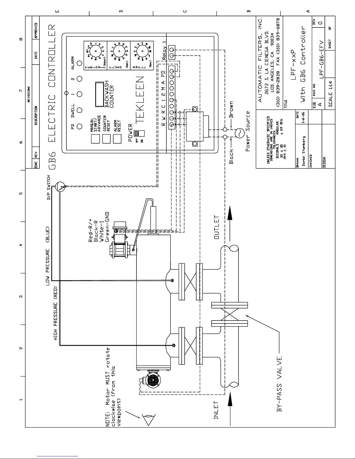
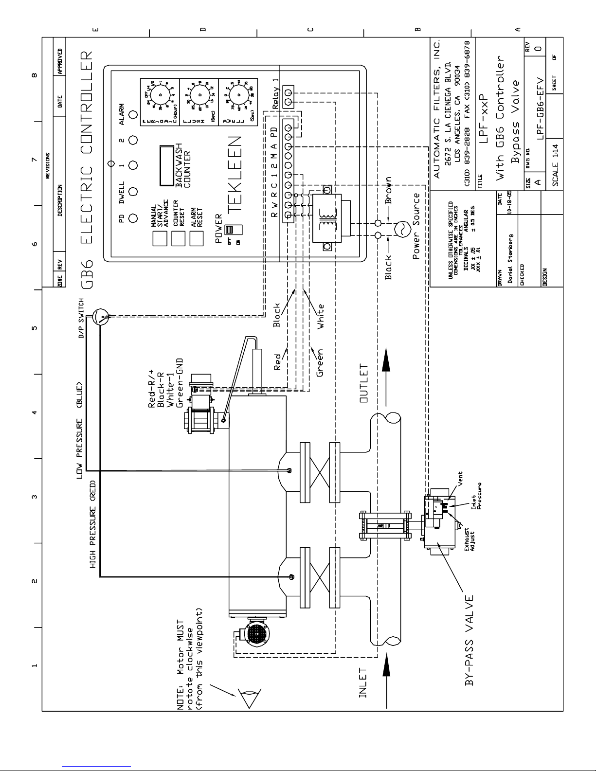
LPF with GB6 Controller 18
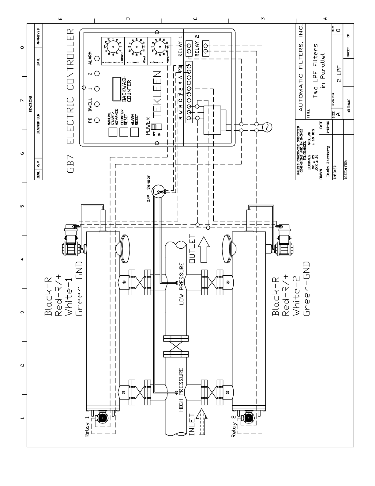
2XLPF with GB7 Controller 19
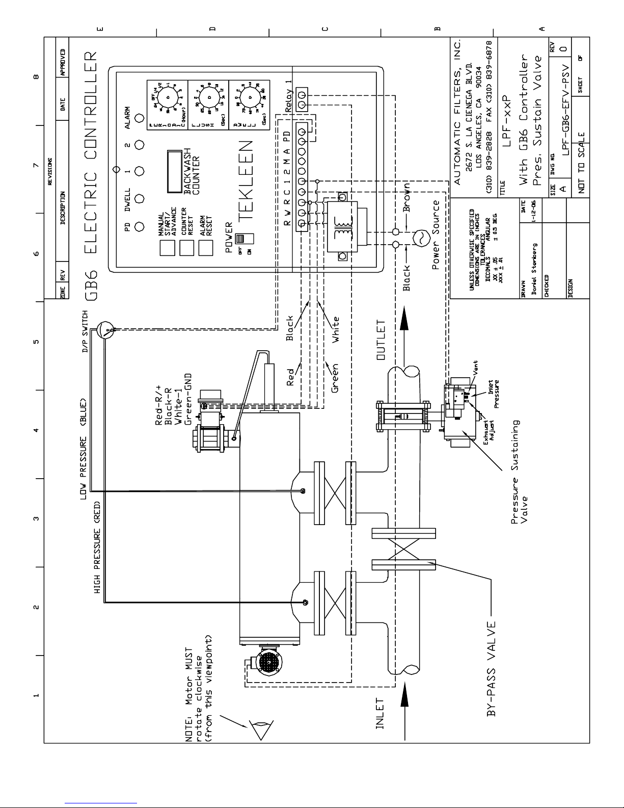
LPF with Pressure Sustaining Valve 20
LPF with Bypass Relief Valve 21
WARRANTY 22
Automatic Filters, Inc.
LPF Filters Manual
Page 3

SECTION I INTRODUCTION
1.1 Description
The LPF series models (Low Pressure Filter) are automatic, self cleaning
screen type water filters. The filtration system consists of a tank body with
a coarse screen, fine screen, electric motor, single flush valve and an
electronic controller.
1.2 Theory of Operation
Pressurized water enters the filter inlet and travels through the coarse screen
from the outside in. The water then travels through the fine screen from the
inside out where small contaminants (down to 25 microns) are filtered. The
clean water then exits through the outlet.
When the fine screen becomes contaminated, a pressure differential is
sensed causing the automatic controller to open the flushing valve and start
the electric motor. When the flushing valve opens, the pressure in the
hydraulic motor chamber is reduced causing the clean water to reverse flow
at the nozzles through the filter element pushing contaminants off the screen,
through the dirt collector and out the flushing valve.
The electric motor rotates the dirt collector as water passes through the nozzles.
Lateral movement allows the dirt collector to vacuum the entire screen.
When the screen is clean, the unit automatically closes the electric valve,
returning the filter to normal operation.
The entire cleaning cycle takes approximately 10-15 seconds. It should be
noted that even during the backflush cycle the filtration process continues
uninterrupted.
1.3 Recommended Applications
Tekleen filters are ideal for filtering out silt, scale, sand, rust, dirt and organic
material like algae, zebra mussels, and clams from virtually all types of water
sources.
Automatic Filters, Inc.
LPF Filters Manual
1
Page 4

1.4 Design Features
Among the many features of the LPF models is the avoidance of the danger
of forcing contaminated water back into the system, which often happens
with sand filters. Tekleen filters will deliver clean water or no water at all.
The most predominant feature is its ability to remove organics such as algae
and other suspended particles.
All filter internal elements can be removed and disassembled from the filter
body without disruption of the plumbing.
The backwash cycle, Tekrinse, uses 90% less rinse water than other filters
on the market today.
For special constructions and applications, see Appendix I, page 13.
Automatic Filters, Inc.
LPF Filters Manual
2
Page 5
1.4 Filter Specifications Chart
Model Flange Size
inches
LPF3SP
LPF4LP
LPF4P
LPF4LPE
LPF4LP
LPF6P
LPF6XLP
LPF6LP
LPF6SP
LPF8P
LPF8LP
LPF8SP
LPF10P
LPF10LP
LPF12P
LPF12LP
LPF14P
LPF14LP
LPF16LP
LPF16SP
LPF18SP
LPF20SP
3
3
4
4
4
6
6
6
6
8
8
8
10
10
12
12
14
14
16
16
18
20
Screen Area
sq. ft.
1.4
2.5
1.4’
2.5
5
2.5
8
5
7
5
8
7
7
11
11
12.5
12.5
16
16
24
24
24
Max Flow
gpm
200
300
300
400
500
600
800
800
1,750
1,320
1,500
1,750
1,750
2,630
2,630
4,000
4,000
6,000
6,000
7,000
8,000
10,000
Specifications: Carbon steel body with baked on powder epoxy coating or stainless
steel 316L body at the same price. Internal parts: stainless steel dirt collector,
stainless steel screen. Maximum 150 psi, 200° F. Standard screen mesh 50µ
to 1000µ. Optional high temperature, and high pressure.
1.5 Measurement Conversion Table
Mesh
Micron
Inch
20
850
.033
40
590
.016
60
250
.010
80
177
.007
Automatic Filters, Inc.
LPF Filters Manual
100
150
.006
140
105
.004
200
74
.003
325
44
.002
550
25
.001
3
Page 6
SECTION II INSTALLATION AND HOOK-UP
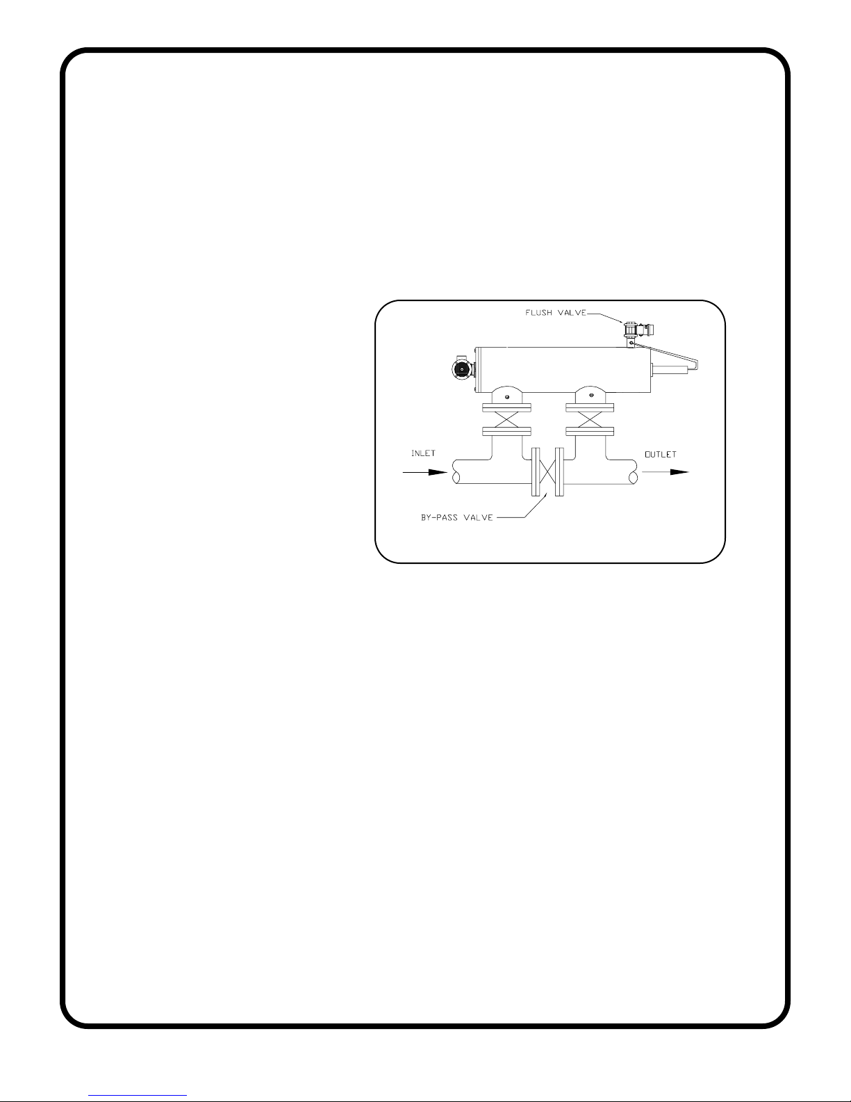
2.1 Mechanical Hook-Up and Orientation
The positioning of the filter tank should be determined by the disposal of
waste water and to allow easy access and removal of filter element (Consult
manufacturer for required clearances).
The Tekleen filter can
rest on the inlet and
outlet flanges or can be
mounted on a stand if
desired.
The electronic controller
should be mounted in
close proximity to the
filter tank.
2.2 Plumbing Hook-Up
The waste discharge pipe should be at least one inch larger in diameter than
the size of the discharge valve (1” valve to 2” pipe & 2” valve to 3” pipe).
The waste pipe should be kept as short as possible with no more than one elbow.
Discharge lines should not be elevated. This will affect the pressure difference
required for the cleaning cycle. If it is necessary to run discharge lines uphill,
please consult with the manufacturer.
Note: A block valve should be installed immediately upstream of the filter.
During start-up, the block valve should only be barely cracked open to prevent
a surge of pressure across the filter when the pump is started. Once the
pump is on-line, slowly open the block valve. This would prevent any possible
damage to the filter due to a pressure surge.
STANDARD HOOK-UP AND ORIENTATION
Automatic Filters, Inc.
LPF Filters Manual
4
Page 7

2.3 GB6, DP Gauge, and Electric Ball Valve Connection
Before power is applied to the electronic controller, make all connections
between controller, DP Gauge, and electric ball valve (see page 18).
1. BALL VALVE: Plug controller into appropriate power source. Activate
manual start switch and visually inspect the open and close movement
of the ball valve.
2. FLUSHING TIME ADJUSTMENT: The flush time is normally set to 10
seconds. Flush time should be adjusted to allow piston indicator pin to
reach the end of the slot during one backwash cycle. NOTE: Excessive
flush time will not improve cleaning, and may lead to filter damage.
3. PRESSURE DIFFERNTIAL ADJUSTMENT: The differential switch is preset for 7 psi. It can be changed to different set points (see your electronic
controller manual).
USING 1/4 INCH DIAMETER TUBING
1. Attach tubing to the low pressure 1/4" fitting (on the outlet flange). Attach
the other end of the tubing to the fitting on the DP switch marked “low”
pressure.
2. Attach tubing to the high pressure 1/4" fitting (on the inlet flange). Attach
the other end of the tubing to the fitting on the DP switch marked “high”
pressure.
3. If the filter comes with a piston, attach tubing to the end of piston. Attach
the other end to the fitting on the flush outlet (before the flush valve).
Important Notes: Do not run tubing more than three feet in length (preferably
two feet or less). Due to the pressure drop across the tubing, the
electronic controller may not operate properly if tubing is too long.
Automatic Filters, Inc.
LPF Filters Manual
5
Page 8

Electronic controller should be sealed completely to avoid moisture
from entering. This will prevent possible shorting of circuits.
For more operating details and set-up, please refer to your electronic rinse
controller manual.
SECTION III OPERATION AND ADJUSTMENTS
3.1 Start-Up
During start-up, the block valve at the filter inlet should be cracked open to
prevent a surge of pressure across the filter when the pump is started. Once
the pump is on-line, slowly open the block valve. This will prevent any possible
damage to the filter due to a pressure surge.
During the initial filling of the main pipeline, there may not be enough back pressure downstream from the filter to allow the cleaning cycle to function
properly. Therefore, it is necessary to install a valve on the outlet line to be
partially closed (i.e., gate valve, ball valve or butterfly valve).
If a downstream main line valve is partially closed, enough to provide 15 psi
on the filter inlet pressure gauge, the self cleaning cycle will operate properly .
Once the total system is fully charged, the downstream valve can be adjusted,
as long as 15 psi is maintained at the inlet flange during the backwash cycle.
If systems are to come on automatically , it is advisable to install a flow control
or a pressure sustaining valve downstream from filters to create backpressure
on filters in order to enable proper flushing while pipe lines are being filled.
Once the system is fully charged push the manual flush button on the
electronic controller, check the rotation of the electric motor on the end cover.
The motor should turn clockwise during the flush cycle.
Automatic Filters, Inc.
LPF Filters Manual
6
Page 9
3.2 Back-Flush Requirements
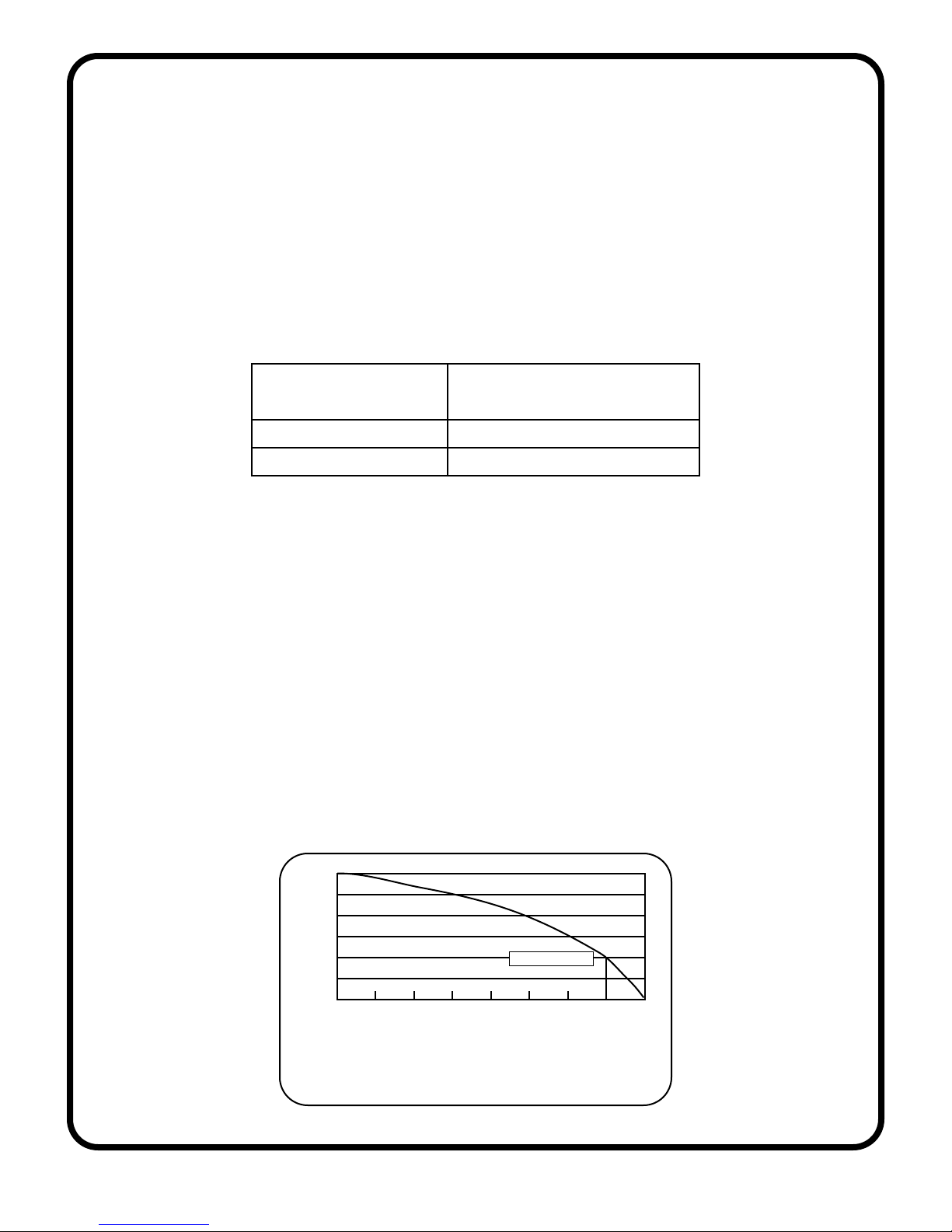
The filter needs a minimum flow and pressure during the backflush process
to guarantee a fully effective cleaning.
The minimum flow depends on the size of the filter’s flush outlet and the
pressure during backflushing. The table below gives an indication of the
required flows.
Flush Outlet Size Flush Flow at 35 psi
(gpm)
1”
2”
40
160
The minimum differential pressure between the filter inlet and the flush outlet
should be at least 15 psi during backwash.
The capacity of the pump has to be sufficient to keep the pressure over 15
psi during backflushing at a flow of process flow + rinse capacity.
For example (see Fig. 3.1):
Process flow is 210 gpm and rinse capacity is 90 gpm
Pressure < 15 psi yields poor cleaning.
Process flow is 130 gpm and rinse capacity is 90 gpm
Pressure > 15 psi yields good cleaning.
60
50
40
30
20
Pressure (psi)
10
0
0 40 80 120 160 200 240 280 320
Flow (gpm)
CRITICAL POINT
FIGURE 3.1 BACKFLUSHING:
PRESSURE VS. FLOW
Automatic Filters, Inc.
LPF Filters Manual
7
Page 10
SECTION IV MAINTENANCE
4.1 Filter Cleaning
Periodic cleaning and inspection of the coarse screen, if supplied, is necessary
for removal of large particles trapped in the chamber. It is also recommended
that the fine screen be inspected during coarse screen cleaning. In hard
water applications, it is beneficial to wash the fine screen in a mild acid.
Proceed as follows:
1. Turn outlet valve off completely.
2. Open the bypass valve.
3. Close inlet valve.
4. Relieve any residual pressure by detaching the 1/4” plastic tubing from
any fitting.
5. Unscrew nuts and remove lid.
6. Remove coarse screen if supplied.
7. Remove fine screen using screen puller/pusher.
8. Grease all o-rings with waterproof o-ring lubricant.
9. Re-assemble unit.
4.2 Dirt Collector Replacement
If the dirt collector should ever need replacing, follow steps 1 through 7 in
section 4.1 (Filter cleaning). Then remove the dirt collector for inspection.
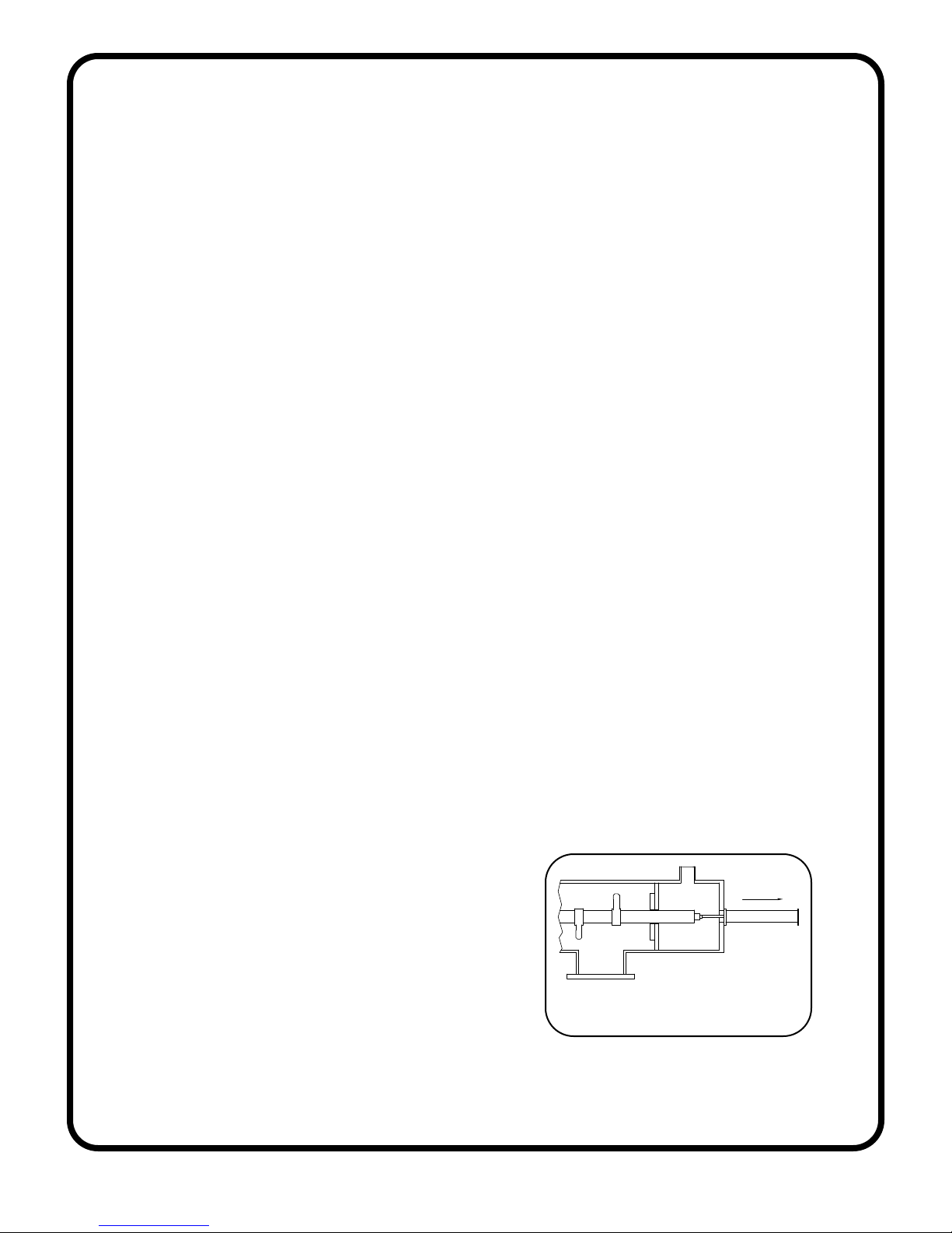
4.3 Piston Removal/Replacement
If the piston needs to be removed or
replaced, follow steps outlined as follows
and refer to Fig. 4.3:
1. Follow steps 1-4, section 4.1
2. Unscrew all connection nuts.
3. Remove piston from the filter housing.
4. Re-assemble unit (reverse procedure).
FIGURE 4.3 PISTON REMOVAL
Automatic Filters, Inc.
LPF Filters Manual
8
Page 11

4.4 Periodic Inspection
The following parts should be inspected annually for wear and tear and
should be replaced if necessary:
- Cover Seal - Coarse Screen
- Fine Screen - O-rings
- Piston - Electric Motor Packing
- Dirt Collector - Upper Bearing
- Lower Bearing - Air/Water Connections
SECTION V TROUBLESHOOTING GUIDE
5.1 Problem: Excessive pressure drop through filter without flushing.
POSSIBLE CAUSE
Controller is not turned on.
SOLUTION
Turn on Power.
POSSIBLE CAUSE
Filter is installed backwards.
SOLUTION
Install filter according to manual drawings.
POSSIBLE CAUSE
Electric valve is wired to the controller incorrectly.
SOLUTION
Verify proper wiring, pages 18-21.
Automatic Filters, Inc.
LPF Filters Manual
9
Page 12

5.2 Problem: Frequent/continuous flushing while filling main pipeline.
POSSIBLE CAUSE
Downstream pressure is not available to provide vacuum cleaning power.
Rapid-filling flow rate exceeds the controllers’ pressure differential.
SOLUTION
Partially close downstream mainline valve; filter inlet gauge should read 15 psi.
POSSIBLE CAUSE
Filter may have been shut down “dirty” with a layer of contaminant that is
difficult to remove after it dries on the screen.
SOLUTION
A Superflush needs to be performed as follows: a downstream mainline
valve should be partially closed to increase inlet working pressure. After the
valve is partially closed, run the filter through several flush cycles. This
process uses the entire available differential pressure in the filter cleaning
process. If this fails, the screen may be removed and cleaned manually.
5.3 Problem: Frequent/continuous flushing during normal operation.
POSSIBLE CAUSE
Very dirty water.
SOLUTION (for electronic controller only)
Increase flushing time so the indicator pin on the piston reaches the end of
the pin grove.
POSSIBLE CAUSE
The set point on the differential pressure switch is set too close to zero,
causing vibration to initiate a flush cycle.
SOLUTION
Increase pressure differential set point.
Automatic Filters, Inc.
LPF Filters Manual
10
Page 13

POSSIBLE CAUSE
Screen may be partially plugged.
SOLUTION
Perform Superflush as described above in section 5.2.
POSSIBLE CAUSE
Dirt collector may be jammed which results in only cleaning the screen area
that is directly in front of the nozzles.
SOLUTION
Open tank and check for free movement of dirt collector mechanism.
POSSIBLE CAUSE
Piston is jammed
SOLUTION
Remove piston from the filter housing and make sure it is moving freely. Orings and U-cups may need lubrication. Check mini-filter for unrestricted flow.
POSSIBLE CAUSE
Coarse screen is contaminated.
SOLUTION
While running, check pressure between filter inlet and hydraulic pressure
chamber (if available). The difference between these two Readings is the
pressure drop through the coarse screen. It should be zero.
.
Automatic Filters, Inc.
LPF Filters Manual
11
Page 14

5.4 Problem: Screen will not clean properly.
POSSIBLE CAUSE
Restriction in flushing valve dump line due to long “run” distance (e.g., running
uphill, 2” line more than 20’ long, 2” line has more than one elbow).
SOLUTION
Increase pipe size, remove any elbows, avoid elevation gain of pipe after
flush valve.
POSSIBLE CAUSE
Filter was shut down “dirty” with a layer of contaminant dried on the screen.
SOLUTION
Perform Superflush as described on Section 5.2, page 10. If unsuccessful,
remove filter screen (see section 4.1, page 8) and spray the screen with a
high pressure hose to remove the contaminant.
SECTION VI SPARE PARTS
6.1 Recommended Spare Parts
The following are recommended spare parts to keep in stock:
- Fine Screen - Set of O-rings
- Cover Gasket - Dirt Collector
- Upper Bearing - Lower Bearing
- D/P Switch - Controller Board
6.2 Spare Parts List
See filter cutaway on page 17.
Automatic Filters, Inc.
LPF Filters Manual
12
Page 15
APPENDICES
Appendix I Special Construction and Features
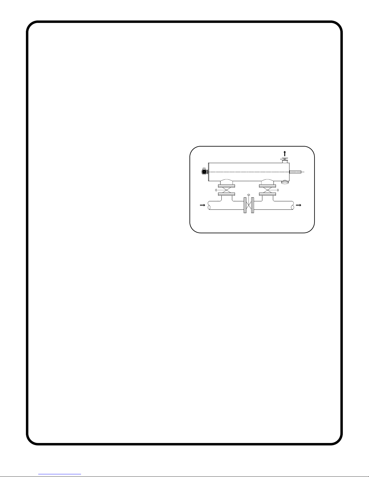
I. (AUTOMATIC) BY-PASS
Sometimes it is necessary to have flow even when the filter is out off service
for periodical maintenance. In this situation, it is recommended to create a
by-pass.
FILTER WITH BY-PASS
It is very simple to create a by-pass,
especially for the on-line models.
To do so, add a block valve on both
the inlet and outlet and a bypass
with another block valve (see
drawing).
FILTER WITH BY-BASS
If the by-pass valves are provided
with actuators, it can be converted to an automatic by-pass system by wiring
it to the control box ( see controller manual).
II. ASME CERTIFIED FILTERS
ASME certified filters for the LPF series are available on special order. The
lead time on these is approximately 30 to 90 days.
III. FILTERS FOR SEVERE APPLICATIONS
The LPF series filters are available in stainless steel construction or
other special alloys for severe applications. Filters with corrosion
resistant coatings are also available. Consult with manufacturer for
availability.
Automatic Filters, Inc.
LPF Filters Manual
13
Page 16
Appendix II System with Discharge to Atmosphere
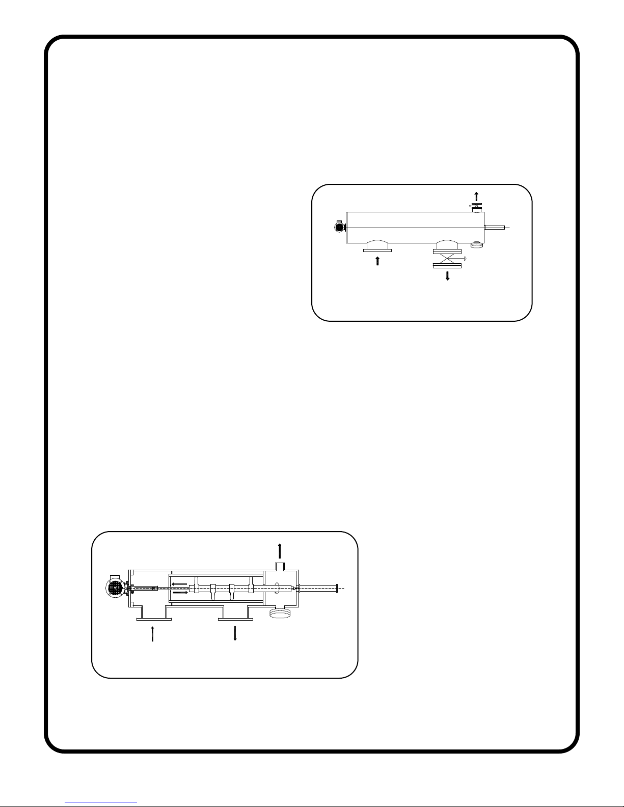
If the filter freely discharges to the atmosphere, it is recommended that a control
valve be installed at the filter discharge. Depending on the process upstream of
the filter, the flow may be higher than the filter handling capacity. In this case, the
control vale at the outlet would be used
to create a back pressure on the system
and control the flow across the filter.
In addition, the discharge valve can be
used as a pressure sustaining valve in
cases where pressure (> 15psi) is not
FILTER WITH DISCHARGE
TO ATMOSPHERE
adequate during backwash.
Appendix III Piston
Due to longer screens on larger filters, it is necessary to employ a piston for the
cleaning mechanism. The piston is used to move and control the linear velocity
of the dirt collector during the rinse cycles. This would enable the dirt collector to
clean the entire surface area of the screen in a spiral-downward movement.
At the end of the cleaning cycle, the flush valve closes and the normal filtration
process resumes. At the same time, the piston is energized with water pressure
which pushes the dirt collector back into position for the next rinse cycle.
FILTER WITH PISTON
Automatic Filters, Inc.
LPF Filters Manual
14
Page 17
Automatic Filters, Inc.
LPF Filters Manual
15
Page 18
16”
20”
14”12”8” 10”6”4”3”2”
PRESSURE DROP DATA
2”
1.5”1”
FLOW RATE (gpm)
Filter Flange Size
10
Automatic Filters, Inc.
LPF Filters Manual
1
1 10 100 1000 2000 10000
0.1
DELTA P (psi)
16
Page 19
Automatic Filters, Inc.
LPF Filters Manual
17
Page 20
Automatic Filters, Inc.
LPF Filters Manual
18
Page 21
Automatic Filters, Inc.
LPF Filters Manual
19
Page 22
Automatic Filters, Inc.
LPF Filters Manual
20
Page 23
Automatic Filters, Inc.
LPF Filters Manual
21
Page 24

WARRANTY
Automatic Filters, Inc. (AFI) warrants its filters and controllers to be free from original
defects for one year from the date of original sale. The manufacturer will replace,
free of charge, any part found defective under normal use and service within the
guarantee period, provided the product is installed, used, and maintained in
accordance with good engineering practice and all applicable instructions or
limitations issued by AFI. The manufacturer assumes no liability for incidental or
consequential damage sustained in the adoption or use of our engineering data,
service, or products. Liability is limited to the repair or replacement of the products.
No agent or representative of AFI has the authority to waive or add to this agreement.
Altered products or use of products in a manner not intended shall void this warranty .
All warranty claims must be sent along with the defective product, freight prepaid
to AFI at its business address. All warranty shipments are for the account of the
buyer. The warranty period shall be 12 months from the date of shipment to the
client.
Automatic Filters, Inc.
LPF Filters Manual
22
 Loading...