

Tekk International XV-100, XU-100, XDC-100, XU-1000 User Manual
XV-100 / XU-100 Portable Radio Manual
* This Servic e manual is subjec t to change accordi ng to improvement of XV-100 / XU-100 Portable
Radio without noti c e.

* Version #2 (2008-12-05)
----- Table of Contents -----
1. XV/XU-100 Features ------------ 3
2. Components of XV/XU-Series Radio ------------ 6
3. Appearance of XV/XU-Series Radio ------------ 7
4. Basic Operation of XV/XU Series Radio ------------ 8
5. Operating XU/XV-100 RADIO ------------ 11
6. Operating Instructions of XV/XU Series Radio ------------ 15
7. Precautions ------------ 26
8. Safety Notes ------------ 28
9. Specification ------------ 30
9.1 XV-100 ------------ 31
9.2 XV-100 ------------ 32
2

1. XV/XU-100 Features
The features of XV/XU-100 are various as below. XV/XU-100 can used under tough industrial
environments as well as public places. XV/XU-100 series have following functions:
z 128 channels and 16 groups are selectable
z Call guard squelch of standardized CTCSS(52) / DCS(104), Invert DCS(104)
z Built-in Scrambler
z Built-in Compander
z Dual Tone Modulation Frequency (DTMF)
z Normal scanning / Priority scanning
z VOX(Voice Operated Transmit)
z Identification origination(2 Tone and 5 Tone)
z BCL(Busy Channel Lock)/BCLO(Busy Channel Lock Out)
z Time-Out Timer (TOT)
z Channel Spacing Only 12.5KHz
z High/Low Power Switching
z Selectable Squelch Level(0~4)
z Monitor
z Lone Worker
z High-Quality Audio Output
z PLL synthesizer method
z DC+3.7V 1,800mAH rechargeable Li-ion employment quantity battery use
z Advanced Speaker Protection technology
z Remote Radio Stun / Kill / Revive (Use 5 tone)
z Various Parameters and PC downloading methods
z PC Tuning
3

1) Numeric LCD Windows
Numeric LCD Windows enable to represent any kind of expression on LCD Display.
2) Built-in Scrambler
Maintaining private and secure communications is increasingly important, with potentially sensitive
information flowing back and forth. The XV/XU-100 Scrambler feature provides enhanced security for
your important public safety and private security communications.
3) Lone Worker
The feature provides added security and safety for individuals who work remotely from their team.
Should a user not respond to a regular warning tone then a defined emergency procedure is activated.
4) Powerful Audio Output
XV/XU-1000 Voice compander audio enhancement and powerful 1W Speaker ensure superb clear,
crisp sound, even in noisy environments.
5) Caller ID (Paging Feature)
XV/XU-1000 have a Caller ID Function that is usually used in the TRS Radio to maximize
communication efficiency and convenience. The caller’s ID is displayed on the right bottom on screen.
6) Power Output Setting Time-out Timer
Programmable power levels provide one of two settings(High/Low) for each of the channels so the
feature allo ws for more effic ient use of channels by radio can be t ailored for mixed t ransmit range
requirements. Output levels can be programmed at 5W/2W on VHF and 4W/2W on UHF.
7) Selectable Squelch Level (0~4)
Helps minimize interference from undesired signals and helps weak signals be heard.
8) 512 Channels and 16 Groups Selectable
Users can use various tones with 53 CTCSS and 104 DCS 512 channels can be divided into 16
groups so that users can make group for other users and page each group.
9) Multi-functional Ear/MIC Jack
With multi-functional Ear/MIC Jack, it is possible to be used together with various accessories.
10) Cloning
For compatibility with current models of TEKK, the data of those models (such as channels, tones, 5-
4
tone ID, etc.) are cloned to another radio with Cloning cable. .
11) Voice Operated Transmit(VOX)
Enjoy the convenience of hands-free operation when used with optional accessories.
12) PC Programming and Tuning
Radio parameter programming and tuning can be accomplished via the accessory connector from a
PC-compatible computer without ever having to open the radio to save both time and expense
(requires optional programming JIG and software)
13) Flash Memory Advantage
Flash memory permits updates, advanced feature sets and system architectural changes to be made
electronically without ever opening the unit. This means fast changes for the system operator and less
down time for users.
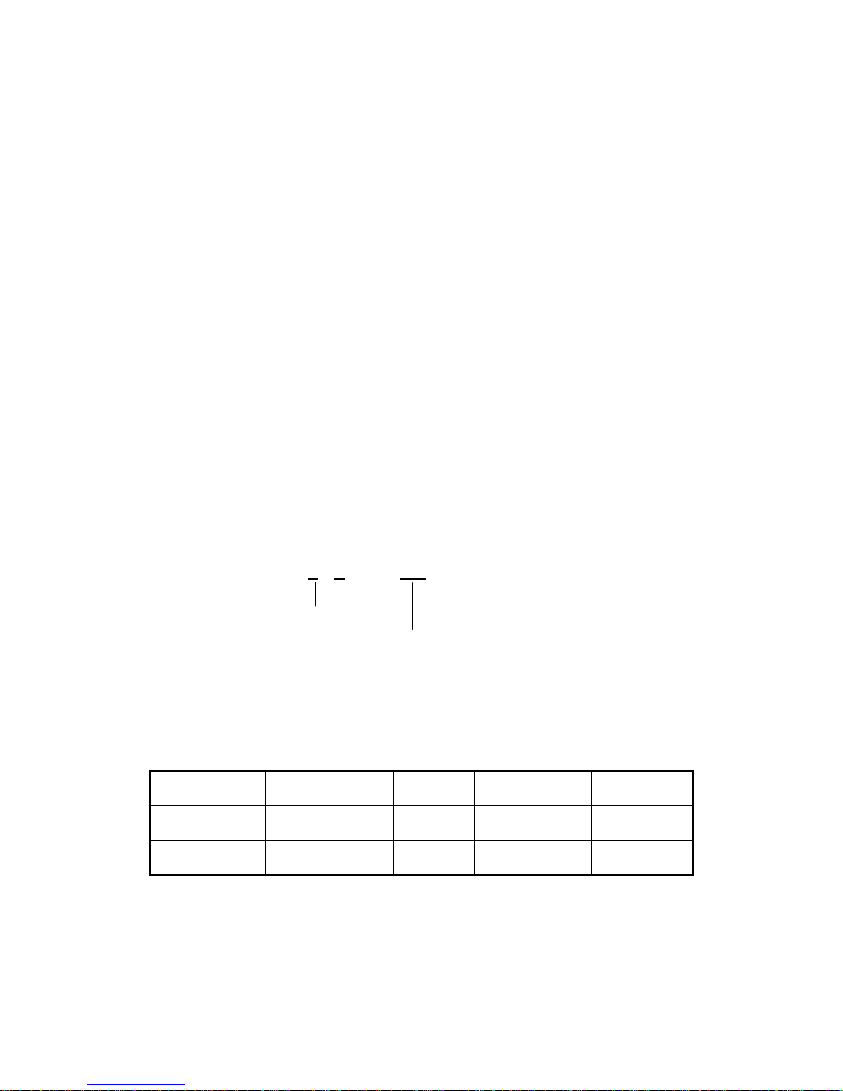
1.1 Part Number Breakdown
The following is a breakdown of the part number used to identify this transceiver
X
U – 100
Enhanced
Or Extreme TEKK International Inc
Radio Version NO
V : VHF Portable Radio
U : UHF Portable Radio
Model History Table
Model Name Frequency Range RF Power Channel Spacing Remark
XV-100 140~170MHz 2Watt 12.5 KHz
XU-100 440~470MHz 2Watt 12.5 KHz
5
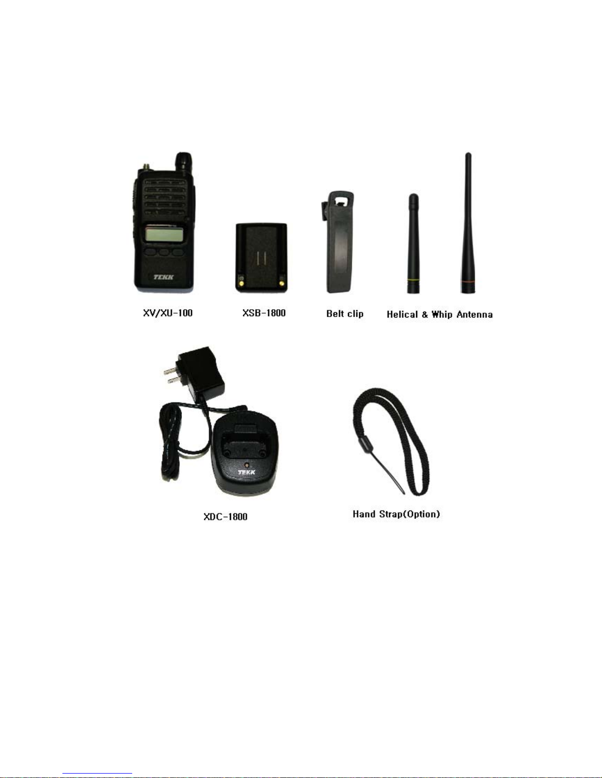
2. Components of XV/XU-Series Radio
* Components could be changed by buyer request.
Figure 1-1) standard components of XV/XU series Radio
6
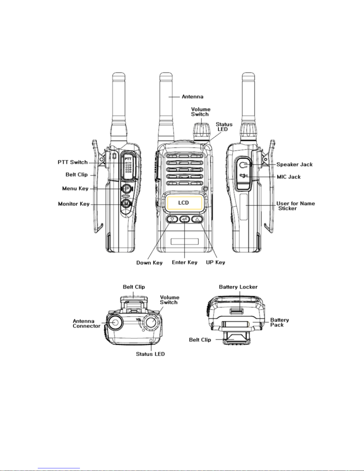
3. Appearance of XV/XU-Series Radio
Figure 3-1) Appearance of XV/XU-100 Series Radio
7
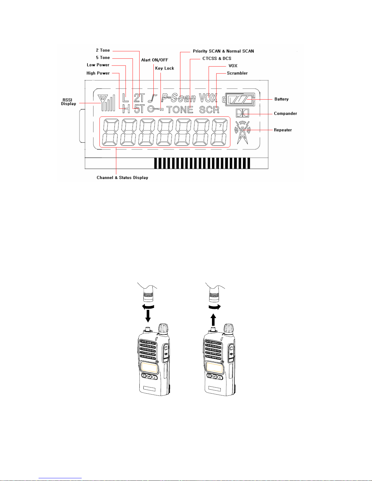
Figure 3-2) XV/XU-100 Series LCD Indication
4. Basic Operation of XV/XU Series Radio
Pease read this manual carefully before using XV/XU series Radio.
This manual contains important information about using Radio.
4.1 Installation and Removing the Antenna
To install the antenna, insert the antenna into antenna connector and screw the antenna clockwise.
To remove the antenna, screw the antenna counter clockwise.
Figure 4-1) Installation and Removing the Antenna
8
When installation of the antenna, giving a strong pressure to the Radio
or pulling the antenna with a strong power from the Radio can make a
damage on the antenna connector, which may cause the Radio to have
a critical problem.
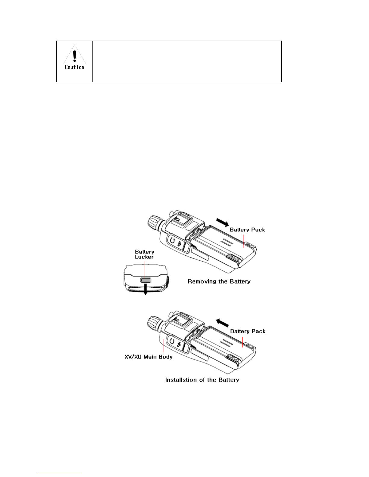
4.2 Installation and Removing the Battery
4.2.1 Installation of the battery
To install battery, slide up the battery towards the top of the radio until battery latch is locked.
4.2.2 Removing the Battery
- Slide the battery latch located on the bottom of radio to the open position as shown in
Figure 4-2.
- The battery is removed by pressing it against and sliding it towards the bottom of the radio
Figure 4-2) Installation and Removing the Battery
9
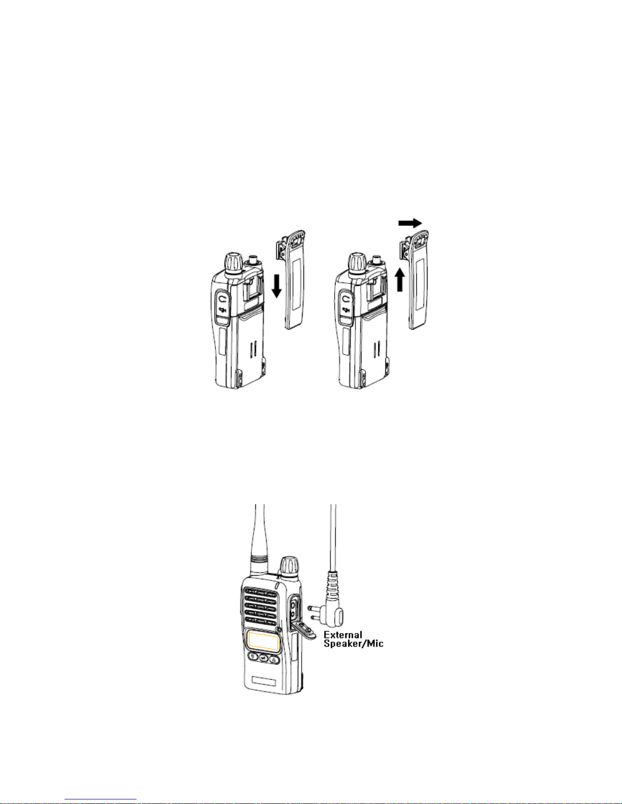
4.3 Installation and Removing the Belt Clip
- To attach belt clip to radio, align belt clip rails with the grooves in radio and slide the belt clip
onto the mounting rails until it latches into place.
- To remove belt clip from radio, push up on tab of belt clip with flat bladed screwdriver and at the
same time, slide the belt clip towards the top of Radio (Figure4-3).
Figure 4-3) Installation and Removing the Belt Clip
4.4 Accessory connector
Accessory connector is used to connect external speaker/Mic, and headset, etc.
Please close the cover when nothing is connected.
10
Figure 4-4) Accessory connector
 Loading...