

Page 1

1
XT-600PLUS(4)
Transceiver
User manual
Page 2

2
Wisetone science & technology Co., Ltd
General
This manual is intended for use by experienced technicians familiar with similar
types of commercial grade communications equipment. It contains main required service
information and data for the equipment.
The following precautions are recommended for personal safety:
1、DO NOT transmit until all RF connectors are verified secure and any open connectors
are properly terminated.
2、SHUT OFF and DO NOT operate this equipment near electrical blasting caps or in an
explosive atmosphere.
3、This equipment should be maintained by qualified technicians only.
Page 3

3
CONTENTS
General
Parts Description
Specification of software
Circuit Description
CPU pins Description
Parts list 1
Adjust Description and specifications
Disassembly for Repair
Component plans
Parts list 2
Packing list
FCB Component locations
Principle View
Principle diagram
Transceiver model and specification
MODEL FREQUENCY(MHz) POWER BATTERY CHARGER
XT-600PLUS(4) 430~470MHz 4W XBP-1250 DC-791 fast charger
Page 4
4
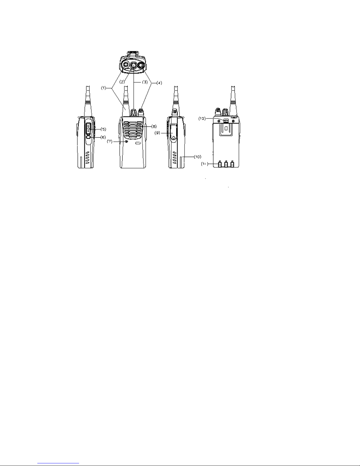
Parts Description
1、
Antenna
The helical antenna is threaded plugs for the reception and transmission signal.
2、LED light
Lights red while transmitting, green while receiving a signal. Flashes red when the battery
voltage is low while transmitting.
3、Channel selector knob
4、Power switch/Volume control Turn the knob clockwise to switch the transceiver ON,
anti-clockwise to turn off the power till there is a ”click” sound , rotate to adjust the volume
level.
5、PTT switch(push to talk)
Press the button while transmitting, and release it while receiving.
6、Monitor key
Press it to shut off squelch, noise could be heard, release to connect squelch.
7、
Microphone
Put in voice.
8、Speaker
Put out voice.
9、Speaker jack
Put down the cover, when you program you can put in the program line in it.
10、Battery
11、Charger plate
Put the battery into the charger, it will operate when the charger plates touch the metal plates.
12、Battery deduction
It use to close the battery, pull it up you can take out the battery.
Page 5

5
Specification of the software function
1、 Turn the volume button can choice 15+1(scan) channels.
2、 Moni function.
3、 CTCSS/CDCSS program
4、 CTCSS: 50 groups
5、 CDCSS: 210 groups
6、 25KHz channel spacing
7、 Scan function, set scan channel.
8、 Power save.
9、 Time- out timer.
10、Voice number notice, program by Chinese/English.
11、VOX function and 9 levels can be choice.
12、9 levels squelch control.
13、Battery low-volt alarm.
14、Set ANI ID code number by program.
15、Remove the squelch tail function.
16、PC model.
17、Manual adjustment model.
18、Clone function
Model description
1、
User mode
Standard model (look for the XT-600PLUS(4) instruction manual)
2、PC mode
Set and adjust the follow function numbers with PC software or programmer.
(1) Channel RX and TX power.
(2) Channel RX and TX tone.
(3) BCL (busy channel lock)
(4) TOT (TX time-out-timer)
(5) Squelch level choice.
(6) Power save function choice.
(7) Voice alarm function choice.
(8) Moni model choice.
(9)Scan channel choice.
(10)VOX level set.
(11)Chinese/English number notice choice.
(12)ANI ID number set.
3. manual adjustment mode
High or low power by manual adjustment
(1)make sure the channel and then close the transceiver.
(2)press the PTT+MONI button to open the transceiver, it will be TX power adjustment
model, the transceiver turn to the TX model.
(3) loose the PTT+MONI button.
(4)press the PTT button one time, the power will increase, press the MONI button one
time, the power will reduce.
(5) After you finish the adjustment please close the transceiver immediately, then if you
open the transceiver again it will operate with the power which you have adjusted.
Page 6
6
4 Clone function
(1)Use the clone line connect clone radio with be-cloned radio.
(2)Turn on the power of the be-cloned radio.
(3)Chose the 16 channel.
(4)Push the MONI button after turn off the power of clone radio, then turn on the power; it
will come into clone model.
(5) If the clone is successful the Green LED will light, or the Orange LED will light.
Circuit Description
一、 Frequency configuration
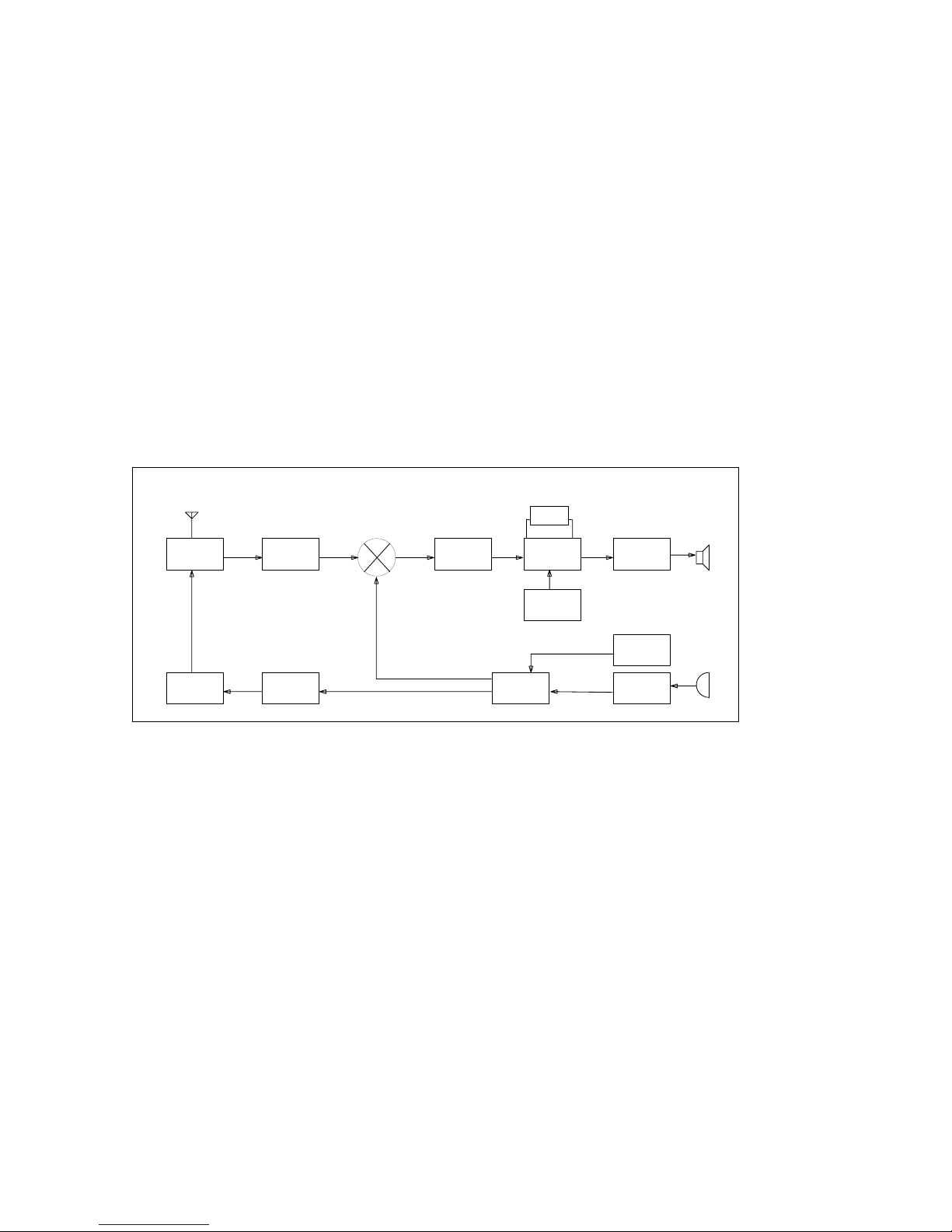
The receiver utilizes double conversion. The first IF is 38.85MHz and the second IF is
450KHZ. The first local oscillator signal is supplied from the PLL circuit. The PLL circuit in
the transmitter generates the necessary frequencies. Fig.1 shows the frequencies.
XT-600PLUS(4) Frequency range: 430 MHz—470MHz
ANTSW RF AMP
TX AMP TX DRIVER
RX
TX
IF AMP
CF 450KHz
IF SYSTEM
38.4MHz
AF AMP
12.8MHz
PLL
VCO
MIC AMP
Fig.1 Frequency configuration
二、
Receiver
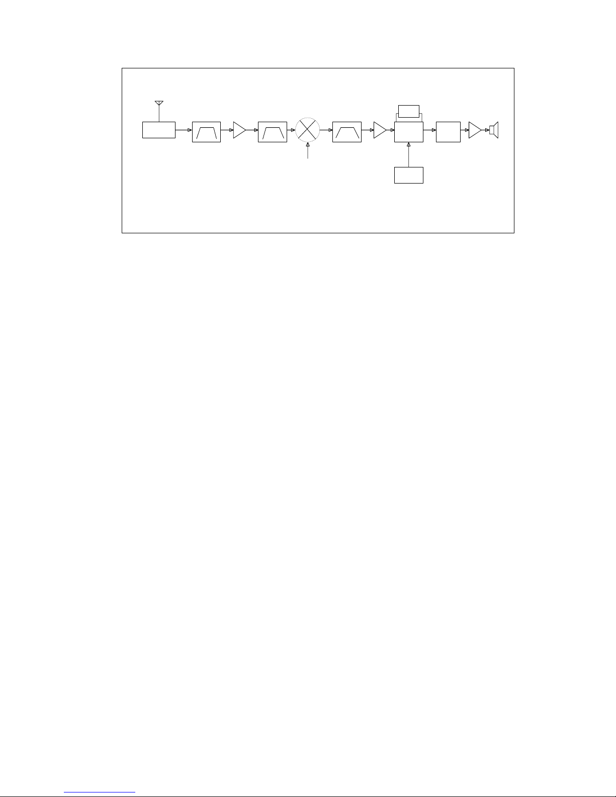
The receiver utilizes double conversion.
1. Front-end RF amplifier
An incoming signal from the antenna is applied to an RF amplifier after passing through a
transmit/receive switch circuit and a band pass filter. After the signal is amplified, the signal
is filtered through a band pass filter to eliminate unwanted signals before it is passed to the
first mixer.
Page 7
7
ANT SW
D211
BPF
RF AMP
T221
BPF
MIXER
T241
MCF
FL251FL253
IF AMP
T251
FL277
IF MIX
U261
38.4MHz
1ST LOCAL OSC
PLL
AF AMP
LPF HPF
AF AMP
SP
U811
U411
Fig. 2 Receiver section configuration
2.
First Mixer
The signal from the RF amplifier is heterodyned with the first local oscillator signal from the
PLL frequency synthesizer circuit at the first mixer (T241) to create a 38.85 MHz first
intermediate frequency (1st IF) signal. The first IF signal is then fed through two monolithic
crystal filters (FL251,FL253) to further remove spurious signals.
3. IF amplifier
The first IF signal is amplified by T251, and then enters U261 (FM processing IC). The
signal is heterodyned again with a second local oscillator signal within U261 to create a
450kHz second IF signal. The second IF signal is then fed through a 450kHz ceramic filter
(FL277) to further eliminate unwanted signals before it is amplified and FM detected in
U261.
4. AF amplifier
The recovered AF signal obtained from U261, and de-emphasized by R264 and
C264. The AF signal is then passed through U811 is amplified and low-pass filter and
high-pass filter. The processed AF signal passes through an AF volume control and is
amplified to a sufficient level to drive a loud speaker by an AF power amplifier (U411).
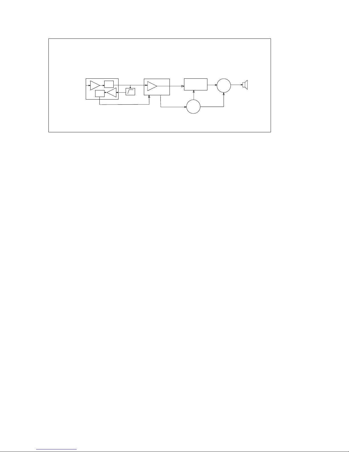
5. Squelch
Part of the AF signal from the U261 is go into the U261 again, and the noise
component is amplified and rectified by a filter and an amplifier to produce a DC voltage
corresponding to the noise level.
The DC signal from the
U261 goes to the analog port of the microprocessor (U811).
U811 determines whether to output sounds from the speaker, U811 sends a high
signal to the MUTE and AFCO lines and turns U411 on through T490. (See Fig.3)
Page 8
8
U261
U811
U411
T498
T490
9
8
14
14
25
22308
2
5
IF AMP
DET
HPF AMP
DET
HPF
BUSY
HPF AMP
MUTE SW
F AMP
SW
SP
Fig.3. AF Amplifier and squelch
6.
Receiving signaling
CTCSS/CDCSS
300 Hz and audio frequencies of the output signal from IF IC are cut by a low-pass
filter. The resulting signal enters the microprocessor (U811). U811 determines whether the
CTCSS or CDCSS matches the preset value, and controls the MUTE SW and the speaker
output sounds according to the squelch results.
Page 9
9
三、PLL frequency synthesizer
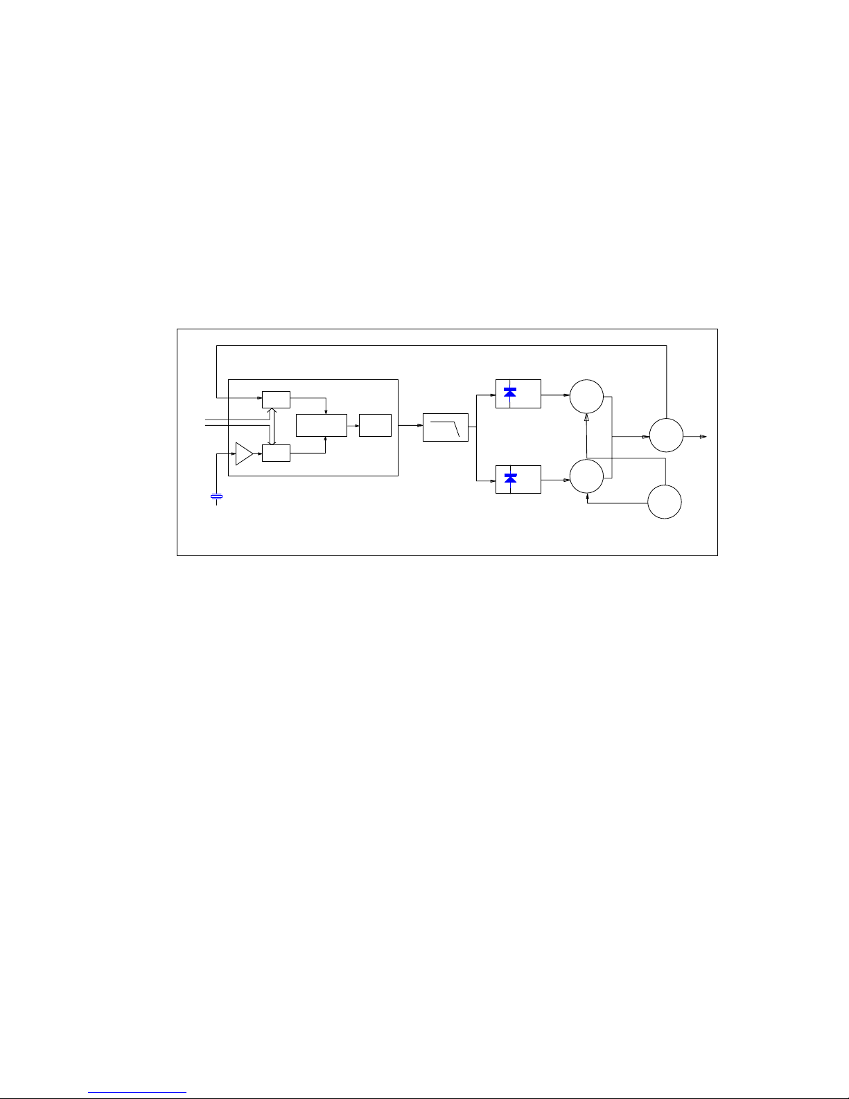
The PLL circuit generates the first local oscillator signal for reception and the RF signal for
transmission.
1. PLL
The frequency step of the PLL circuit is 5 or 6.25KHz. A 12.8MHz reference oscillator
signal is divided at U311 by a fixed counter to produce the 5 or 6.25KHz reference
frequency. The voltage controlled oscillator (VCO) output signal is buffer amplified by T311,
then divided in U311 by a dual-module programmable counter. The divided signal is
compared in phase with the 5 or 6.25KHz reference signal in the phase comparator in U311.
The output signal from the phase comparator is filtered through a low-pass filter and
passed to the VCO to control the oscillator frequency. (See Fig. 4)
CR311
12.8 MHz
PLL IC
U311
PLL DATA
I/N
5KHz/6.25KHz
PHASE
COMPARTOR
CHARGE
PUMP
I/M
5KHz/6.25KHz
LPF
D322
D332
TX VCO
RX VCO
BUFF AMP
T/R SW
T321
T331
T311
T304 T305
Fig. 4 PLL
2.
VCO
The operating frequency is generated by T321 in transmit mode and T331 in receive
mode. The oscillator frequency is controlled by applying the VCO control voltage, obtained
from the phase comparator, to the varactor diodes (D322 in transmit mode and D332 in
receive mode) . The T/R pin is set high in receive mode causing
T304 and T305 to turn
T321off, and turn T331 on. The T/R pin is set low in transmit mode. The outputs from T321
and
T331 are amplified by T311, then sent to the PLL circuit U311 and receiver or
transmitter.
四、Transmitter
3.
Transmit audio
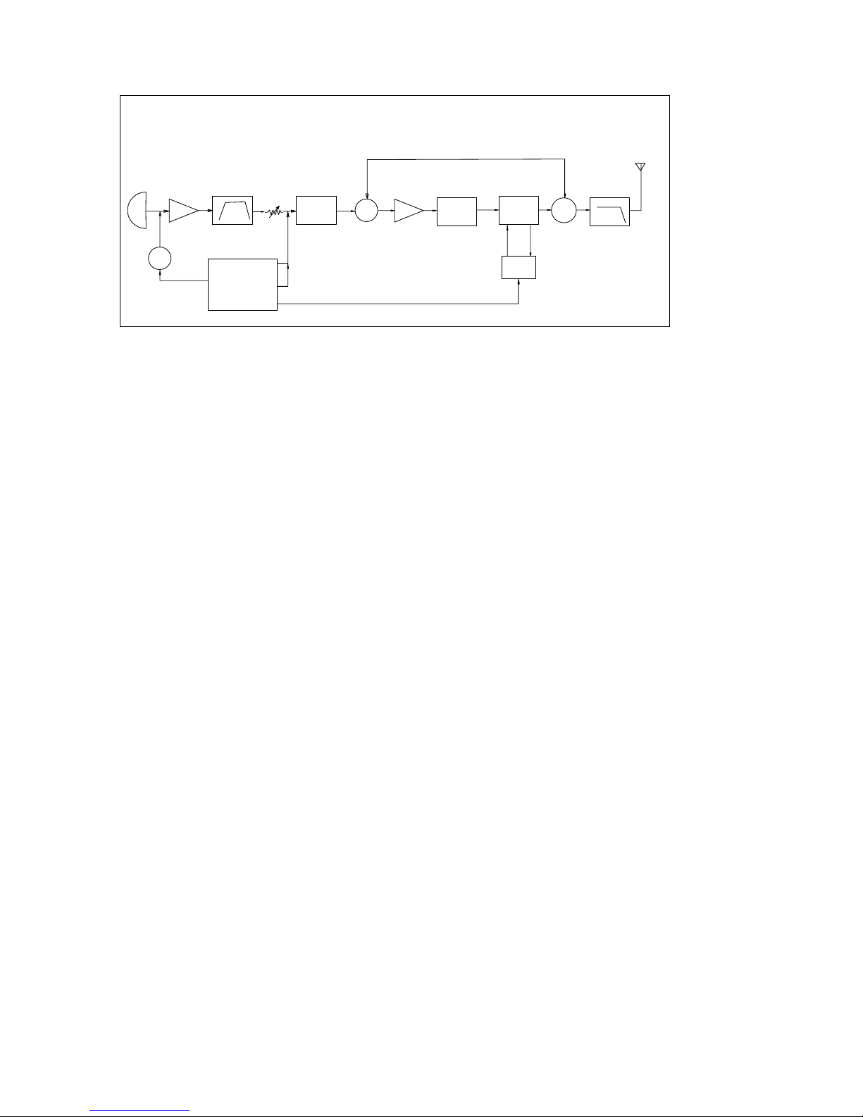
The modulation signal from the microphone is amplified by U421, passes through a
preemphasis circuit, and the signal then passes through a low-pass filter (splatter filter)
(T430 and T433) and cuts up 3kHz and higher frequencies. The resulting signal goes to the
VCO for direct FM modulation. (See Fig. 5)
4. CTCSS/CDCSS encoder
A necessary signal for CTCSS/CDCSS encoding is generated by U811 and FM-modulated to
the PLL reference signal. Since the reference OSC does not modulate the loop
characteristic frequency or higher, modulation is performed at the VCO side by adjusting
the balance. (See Fig. 5)
Page 10
10
MIC
T417
SW
U421
MIC AMP
T430,T433
BPF
VCO
D321,D322
U811
CPU
MUTE
31
44
71
20
DQT
DTMF
APC
SW
D141
T140
TX AMP
T130
TX DRIVER
T120
TX AMP
APC
U161
SW
D111,D112
LPF
5T
Fig. 5. Transmit audio CTCSS
5.
RF amplifier
The transmit signal obtained from the VCO buffer amplifier T311, is amplified by T140. This
amplified signal is passed to the power amplifier T130 and T120, which consists of a 2
stage FET amplifier and is capable of producing up to 4W of RF power
6. ANT switch and LPF
The RF amplifier output signal is passed through a low-pass filter network and a transmit/receive
switching circuit before it is passed to the antenna terminal. The transmit/receive switching circuit is
comprised of D111 and D112. D111 and D112 turned on (conductive) in transmit mode and off (isolated)
in receive mode.
五、Power supply
A 5V reference power supply for the control circuit is derived from an internal battery. This power is
used to provide a 5V supply in transmit mode [5T], a 5V supply in receive mode [5R] , and a 5V, supply
common in both modes based on the control signal sent from the microprocessor.
六、Control system
The IC U811CPU operates at 32.768kHZ.
Page 11

11
CPU pins Description
PIN No. PIN NAME I/O DESCRIPTION
1 PC0 I/O RS-232C output
2 PC1 I/O Input encode
3 PC2 I/O Input encode
4 PC3 I/O Input encode
5 PC4 I/O Input encode
6 PC5 O Red light control
7 PC6 O Green light control
8 PC7 O TX Power control
9 PB3 O VCO Power control
10 PB4 O RX Power control
11 PB5 I MONI Button
12 AVdd I CPU input power 5V
13 RXO O Input QT/DQT signal
14 RXI I AF amplifier
15 TXI NC
16 TXO NC
17 TONE O DTMF output
18 LC Capacitance input
19 AVSS Grounding
20 D/A O APC/AFC
21 ATX O RS-232C output
22 ARX O Audio output
23 AD1 I Detect battery voltage
24 AD2 I VOX check
25 AD3 I Input busy signal
26 OSCI I Oscillator
27 OSCO O Oscillator
28 Vss Connect VSS
29 PD1 O Audio IC control
30 PD2 O Squelch control
31 PD3 O MIC mute control
32 RESET I Reset
33 Vdd I CPU input power 5V
34 PA0 I/O EEPROM data cable
35 PA1 I/O EEPROM clock cable
36 PA2 I/O EEPROM enable
37 PA3 I/O PLL data output
38 PA4 I/O PLL clock output
39 PA5 I/O PLL LE
40 PA6 I/O Lock circuit detector
41 PA7 I/O RS-232C input
42 PB0 I PTT Button
43 PB1 O Wide or narrow control
44 PB2 O Output QT/DQT
Page 12

12
XT-600PLUS(4) Parts list
Material
code
Size Description
Preci
sion
QUA A Ref.No
B Ref.No
R5-F0R1-00 2512 0.1R/1W F 1 R121
R2-J000-00 0402 0R J 14
R886.R835.R456.R410.R436
R264.R566
R376,R370,R101,R103,R135
R267,R364
R2-J2R2-00 0402 2.2R J 1 R473
R2-J100-00 0402 10R J 1 R440
R2-J220-00 0402 22R J 1 R142
R2-J330-00 0402 33R J 1 R313
R2-J470-00 0402 47R J 4 R361,R305,R132,R131
R2-J680-00 0402 68R J 1 R245
R2-J101-00 0402 100R J 11 R564.R554.R439.R804
R584,R311,R304,R257,R136
R244,R221
R2-J151-00 0402 150R J 3 R822.R821
R360
R2-J181-00 0402 180R J 5 R380,R331,R321,R314,R312
R2-J221-00 0402 220R J 3 R256,R246,R113
R2-J561-00 0402 560R J 1 R365
R2-J681-00 0402 680R J 3 R515 R253,R273
R2-J102-00 0402 1K J 10 R838.R824.R823.R455.R458 R482,R478,R373,R366,R362
R2-J102-00 0402 1.2K J 1 R414
R2-J182-00 0402 1.8K J 3 .R437.R425 R581
R2-J222-00 0402 2.2K J 1 R368
R2-J272-00 0402 2.7K J 4 R316,R146,R133,R262
R2-J332-00 0402 3.3K J 6 R438.R434 R255,R272,R263,R582
R2-J392-00 0402 3.9K J 0
R2-J472-00 0402 4.7K J 14
R516.R873.R872.R426.R871
R371,R595,R594,R593,R591
R363,R243,R242,R367
R2-J512-00 0402 5.1K J 1 R417
0402 5.6K J 1 R562
R2-J682-00 0402 6.8K J 1 R147
R2-J822-00 0402 8.2K J 2 R556, R143
R2-J103-00 0402 10K J 17
R452,R151,R153,R430,R433
R511
R296,R481,R335,R333,R322
R315,R307,R306,R148.R249
R291
R2-J153-00 0402 15K J 2 R885 R241
R2-J183-00 0402 18K J 3 R552.R412.R159
R2-J203-00 0402 20K J 3 R563.R553.R442
R2-J223-00 0402 22K J 6 R833.R494.R419.R857 R385,R383
R2-J333-00 0402 33K J 8
R441.R432.R431.R429,R427
R158. R379,R378
R2-J393-00 0402 39K J 2 R862.R157
R2-J473-00 0402 47K J 9
R808.R806.R803.R802.R801
R372.R154,R592 R110
R2-J513-00 0402 51K J 0
R2-J563-00 0402 56K J 2 R852 R218
R2-F683-00 0402 68K F 1 R855
R2-J823-00 0402 82K J 2 R884.R854
R2-F104-00 0402 100K F 13 R883.R493.R444.R231.R411
R325,R323,R215,R227,R224
R216,R392,R391
R2-J124-00 0402 120K J 2 R567.R551
R2-J154-00 0402 150K J 10
R832.R831.R167.R166.R165
R164.R163.R161 R369,R254
Page 13

13
R2-J224-00 0402 220K J 2 R561.R155
R2-J274-00 0402 270K J 1 R268
R2-J334-00 0402 330K J 2 R512.R445
R2-J474-00 0402 470K J 4 R491.R413.R421 R271
R2-J105-00 0402 1M J 1 R152
R2-J185-00 0402 1M8 J 2 R428.R404
R2-J475-00 0402 4.7M J 2 R492 R475
RP-0473-00 RP-1206-4 47K 2 PR804.PR801
RP-0472-00 RP-1206-4 4.7K 1 PR805
RP-0102-00 RP-1206-4 1K 1 PR802
RT-0103-00 RV1208 10K 1 RV422
RT-0503-00 RV1208 50K 2 RV266.RV361
C2-B0R5-00 0402 0.5P B 2 C326,C325
C2-B010-00 0402 1P B 0
C2-B1R5-00 0402 1.5P B 1 C252
C2-B020-00 0402 2P B 3 C363,C311,C116
C2-B030-00 0402 3P B 5 C134,C249,C247,C323,C226
C3-B090-00 0603 3P B 1 C126
C2-B040-00 0402 4P B 0
C2-B050-00 0402 5P B 1 C322
C2-B060-00 0402 6P B 7
C332,C333,C315,C243,C236
C214,C117
C3-B070-00 0603 7P B 2 C125,C713
C2-B070-00 0402 7P B 4 C253 C143,C228,C383
C2-B080-00 0402 8P B 1 C312
C2-B090-00 0402 9P B 4 C146,C115,C225,C223
C3-B070-00 0603 9P B 1 C128
C2-B100-00 0402 10P B 2 C321,C112
C2-B120-00 0402 12P C 4 C224,C215,C324,C136
C2-B130-00 0402 13P C 1 C216
C2-B150-00 0402 15P C 4 C227,C331,C328,C334
C2-B180-00 0402 18P C 1 C218
C2-B220-00 0402 22P C 2 C211.245
C3-B220-00 0603 22P C 1 C111
C2-B240-00 0402 24P C 1 C212
C3-B240-00 0603 24P C 0
C2-B270-00 0402 27P C 5 C882.C811.C596.C597 C213
C2-B330-00 0402 33P C 5 C144,C251,C237,C235,C291
C2-B390-00 0402 39P C 0
C2-B470-00 0402 47P C 2 C492 C133
C2-B560-00 0402 56P C 1 C292
C2-B820-01 0402 82P C 2 C262,C135
C2-J101-00 0402 100P J 5 C161 C362,C368,C367,C366
0402 120P J 1 C387
C2-J221-00 0402 220P J 6 C838.C471.C454.C852.C458 C472
C2-J331-00 0402 330P J 2 C271,C268
C2-J471-00 0402 470P J 20
C823.C661.C554.C447.C436
C403.C152.C164
C583,C364,C360,C335,C307
C306,C304,C142,C113,C451
C392,C906
C3-J471-00 0603 470P J 1 C122
C2-J681-00 0402 680P J 1 C429
C2-J681-00 0402 820P J 1 C433
C2-k102-00 0402 102P K 13
C151,C162,C430,C432,C365
C377,C372,C370,C361,C118
C371,C293,C132
C2-k222-00 0402 222P K 2 C266,C265
Page 14

14
C2-k392-00 0402 392P K 1 C856
C2-J472-00 0402 472P J 5 C264,C595,C591,C412,C871
C2-k103-00 0402 103P K 29
C513.C885.C854.C435.C388
C163.C153.C105.C402
C202,C201,C102,C101,C301
C141,C148,C256,C255,C254
C246,C241,C231,C234,C233
C232,C221,C277,C907,C905
C2-k223-00 0402 223P K 3 C389.C426,C431
C2-k273-00 0402 273P K 2 C414.C413
C2-k333-00 0402 333P K 1 C855
C2-J473-00 0402 473P J 1 C872
C2-k563-00 0402 563P K 1 C411
C2-k104-00 0402 104P K 33
C516.C514.C512..C886
C883.C864.C857.C851.C837
C836.C833.C822.C555.C494
C493.C491.C445.C441.C440
C410,C155.C457.C455
C296,C376,C375,C309,C103
C282,C281,C278,C382,C473
C2-k224-00 0402 224P K 3 C417 C263,C261
C2-Z105-00 0402 105P Z 3 C446,C452 C477
C5-Z475-00 0805 4.7uF Z 11 E151.C415
E371,C475,C474,E422,C257
C121,C123,C276,C124
C5-J104-00 0805 0.1uF J 2 E363,E361
C5-k105-00 0805 1uF Z 2 C106 E362
CA-T225-16 A 2.2uF/16V M 2 E417.E435
CA-T106-10 A 10uF/10V M 5 E871.E854 E365,E907,E905
CA-T105-16 A 1uF/16V M 1 E491
CA-T475-16 A 4.7uF/16V M 2 E373,C305
CB-T226-16 B 22uF/16V M 2 E481,E261
CC-T107-06 C 100uF/6V3 Z 1 E473
CT-0060-00 6PF 2 CV331,CV321
L9-0301-00
0603 301T
1 L886
L9-0101-00
0603 101T
4 L851.L101
L376,L391
L3-0682-01
0603 6.8nH
2
L142,L134
L3-0273-01
0603 27nH
2
L311,L237
L3-0475-00
0603 4.7uH
1 L454
L3-0104-00
0603 100nH
2
L221,L362
L3-0105-00
0603 1uH
1
L291
L3-0224-00 0603 220nH
6
L333,L331,L323,L321,L135
L113
L3-0333-00
0603 33nH
2
L141,L131
L3-0824-00
0603 820nH
1
L243
L3-0223-00
0603 22nH
1
L247
L3-0183-00
0603 18nH
1
L361
L9-2811-06
0.28X1.1X
6TL
6T
4
L216.L224.L227.L215
L9-3516-07
0.35X1.6X
7TL
7T
1
L121
L9-0514-04
0.5X1.4X4
TL
4T
3
L211.L111.L112
L9-0311-03
0.3X1.1X3
TL
3T 1 L322
L9-0315-03
0.3X1.15X
3TL
3T 1 L332
D0-302T-00
SLS-YGUR30
2TM
LED3225
1 D821
D0-0372-00 1SS372 USM 1 D417
D0-0122-00 KDS122 USM 1 D491
D0-0154-00 KDV154 USC 5 D321,D215,D227,D224,D216
Page 15

15
D0-0376-00 MA2S376 2 D332,D322
D0-0131-00 HVC131 ESC 4 D211,D112,D111,D361
D0-0114-00 KDS114 USC 2 D141,D249
Q0-4008-00 PD54008L 2-5N1A 1 T120
Q0-3078-00 2SK3078 SOT89 1 T130
Q0-1824-00 2SK1824 ESM 4 T571.T561.T551 T581
Q0-305S-00 KRA305 USM 7 T455.452 T296,T481,T202,T101,T301
Q0-404S-00 KRC404 USM
11 T822.T821.T162.T151.T456
T483,T477,T305,T304,T273
T263
Q0-2014-00 KTA2014 USM 1 T881
Q0-4075-00 KTC4075 USM 3 T417.T433.T430
Q0-4080-00 KTC4080Y USM 1 T251
Q0-4226-00 2SC4226 USM
7
T361,T331,T321,T311,T140
T241,T221
U0-UDIO-00
TMP87P805B
U
QFP44
1 U811
U0-UDIO-00 AUDIO SOP8 1 U511
U0-LC08-00 24LC08 SOP8 1 U835
U0-7233-00 TDA7233 SOP8 1 U411
U0-5002-00
XC62FP5002
PR(5A)
SOT89-5A
1
U906
U0-324V-00 NJM324 SSOP16-225 1 U421
U0-1136-00 TA31136F SSOP16-225 1 U261
U0-2332-01 LMX2332 SSOP20-225 1 U311
U0-2904-00 NJM2904V SSOP8 1 U161
U0-7385-00 LC7385M U-SOP18-245 1 U591
L0-4500-02 6060-2S JTB450CM 1 CR262
Y0-1280-05 DS0305 12.8MHz 1 CR311
Y0-3276-00
DS7325-MC2
06
32.768KHz
1 CR881
Y0-3580-01 FX-CS20 3.58MHz 1 CR596
Page 16
16
Adjust Description and specifications
Use programmer or PC software to program XT-600PLUS(4) , or by manual program , eg . To program
XT-600PLUS(4) by manual as follows:
一、Instrument::
Synthesized test instrument 1 set
Scanner 1 set
3A/10V power 1 set
Digital Voltmeter 1 set
3A DC Ammeter 1 set
二、Adjust:
1、Initialization: It is necessary to initialize the transceiver because there is useless data in
EEPROM. So make initialization before adjust. After set the Initialization data on PC, connect
the radio by program line, then turn on the radio power, you can write in Initialization data.
2、Adjustment: The adjustment of XT-600PLUS(4), some are conducted in PC communication
mode; some are in manual program mode. Turn on the power and enter the manual program
mode.
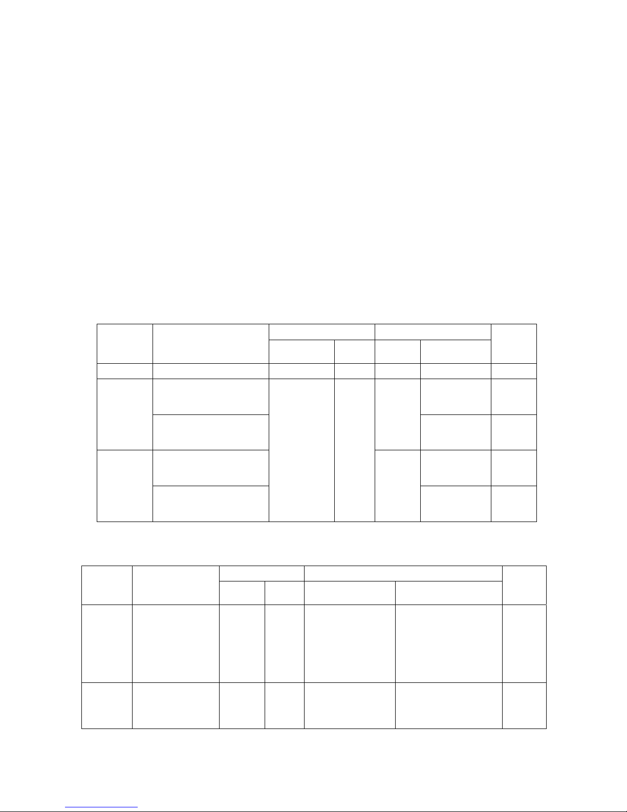
VCO SECTION:
measurement Adjustment
ITEM CONDITION
Test equip terminal part Method
Specificati
ons/Re
mark
1、.Setting 1、power 7.5V
1、TX high frequency,ente
r
the manual program mode
and press the PTT
4.0V±0.1V
2 、 Tran smit
VCO1.CH:
lock voltage
2、TX low frequency,ente
r
the manual program mode
and press the PTT
CV321
>0.7V
1、RX high frequency,ente
r
the manual program mode
and press the MONI
3.8V±0.1V
3 、 Receive
VCO1.CH:
lock voltage
2、RX low frequency,
enter
the manual program mode
and press the MONI
Digital
Voltmeter
CV
CV331
>0.7V
Adjust the Transmitter section:
Measurement Adjustment
Item Condition
Test equip Terminal parts Method
Specificati
ons
/Remarks
7、Transmit
frequency
1、TX center
Turn to manual mode
and press the PTT
Synthetical
test
ANT RV361
Adjust to the center
frequency
the error≤
±250Hz
8、MAX DEV
最大频偏
1、TX center frequency
Turn to manual mode
and press the PTT
Synthetical
test LPF:
15kHz
ANT RV422
Adjust the frequency error
to:4.2kHz±100Hz
Page 17
17
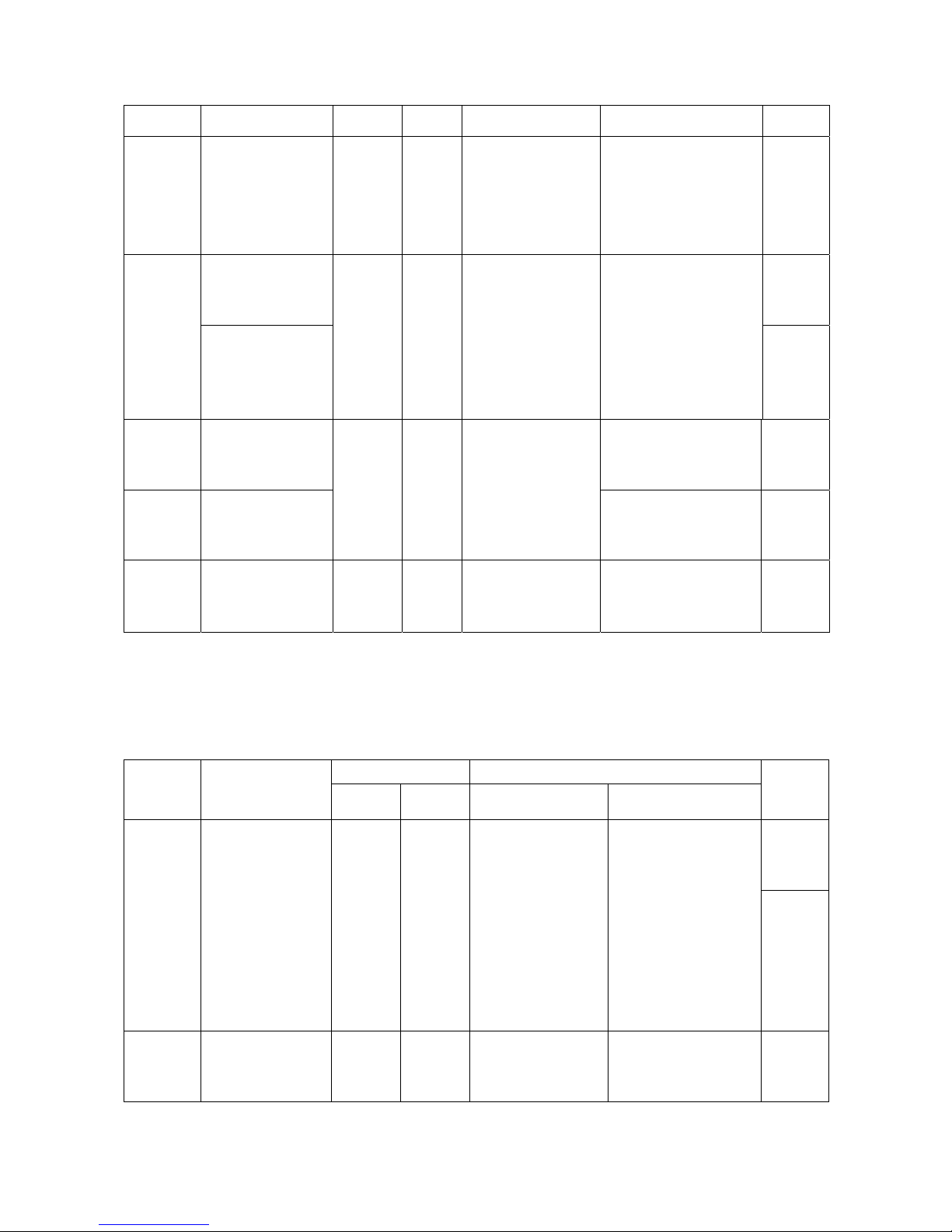
AF:1kHz
120mV
9、FM
Sensitivity
1、TX center
Turn to manual mode
and press the PTT
Synthetical
test
FILTER:
0.3-3.4kHz
AF:1kHz
15mV
ANT
Check frequency
error :2.2kHz-3.6kHz
1、TX center and with
67.0Hz CTCSS, turn
to manual mode
67.0Hz
CTCSS
10、 CTCSS
balance
2、TX center and with
250.3Hz CTCSS, turn
to manual mode an
d
press the PTT
Synthetical
test LPF:
300Hz
ANT
Adjust VR3,the test value of
on
condition 1 & condition 2 is
consistent, the
difference
value<=200Hz
250.3Hz
CTCSS
11 、 CTCSS
frequency
error
1、TX center frequency
CTCSS:67.0Hz turn to
manual mode
Adjust the frequency error
to:0.65kHz±100Hz
12、CDCSS
frequency
error
1、TX center frequency
CDCSS:023 turn to
manual mode
Synthetical
test
LPF:300Hz
ANT
Adjust the frequency error
to:0.65kHz±100Hz
13、.Low
Battery alarm
level
Turn to manual mode,
Adjust the battery to
5.7V
Digital
voltmete
Adjust so that the LED
flashes
Adjust the receiver section: (enter manual mode first)
Measurement Adjustment
Item Condition
Test equip Terminal parts Method
Specificati
ons
/Remarks
4、.Band-pass
filter
1、RX center
turn to channel 4 in
manual mode
Spectrum
analyz
ANT .
Adjust the undee to the
top, the bandwidth is
about 20MHz, the sign o
f
central frequency is in the
middle of the undee
5、Sensitivity
1、RX center
Turn to manual mode
Synthetical
test
SSG
output:
ANT
check
SINAD:
12dB or
higher
Page 18
18
2、RX low
Turn to manual mode
3、RX high
Turn to manual mode
-118dBm
MOD:1KHz
DEV:±3kHz
FILTER:
0.3-3.4kHz
1、RX center
Turn to manual mode
Synthetical
test
SSG
output:
-117dBm
Level 9
Adjust to close the squelch.
Adjust the
Level 9
squelch.
6、Squelch
2、RX center
Turn to manual mode
Synthetical
test
SSG
output:
-125dBm
ANT RV266
Level 3
Adjust to close the squelch.
Adjust the
Level 3
squelch.
Page 19
19
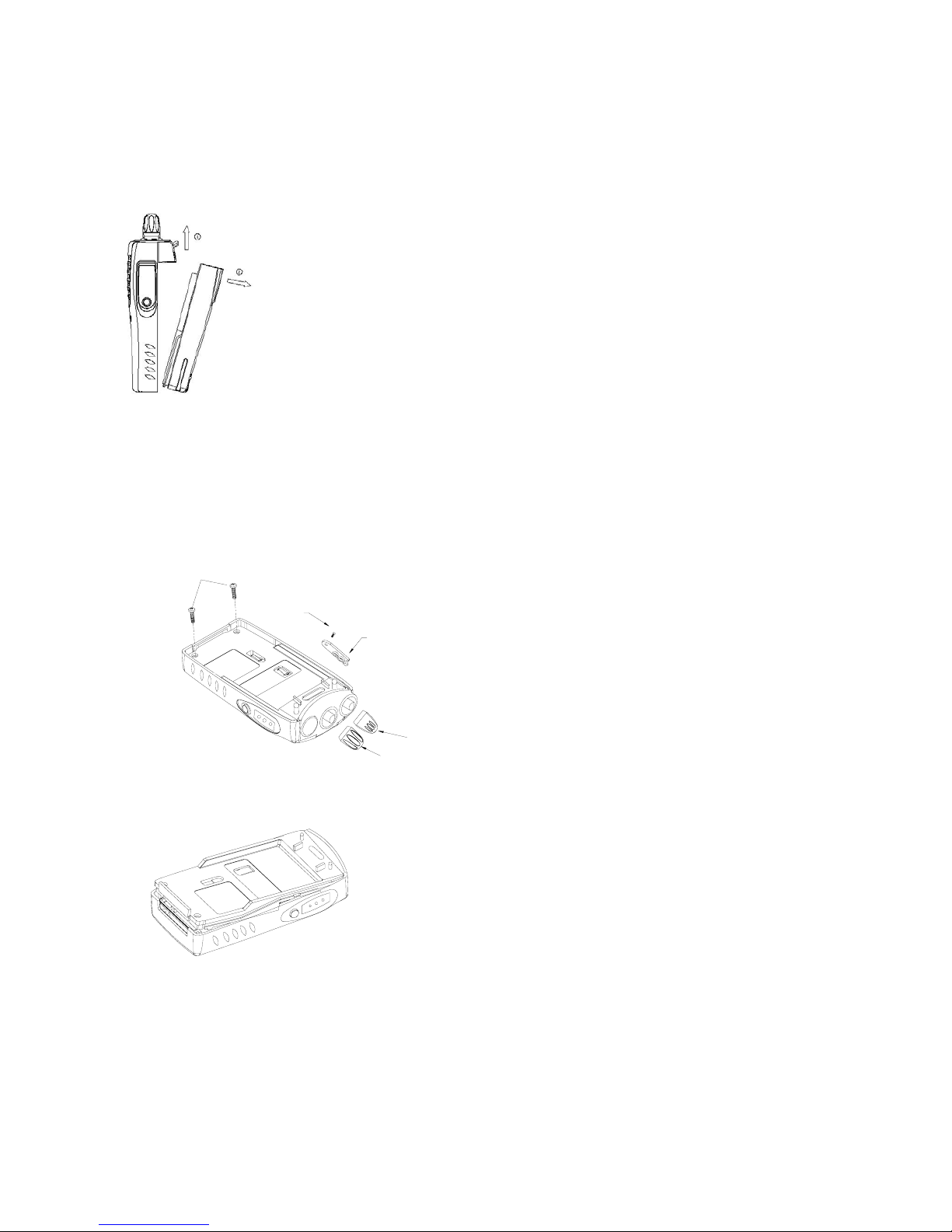
Disassembly for Repair
Put out the battery
Make sure close the transceiver, than press down battery locking tap, and then pull down the battery pack.
Put out the cassette(aluminum hull and PCB board)
1、Put down the 2 crews which in the transceiver bottom.
2、
Pull out the volume knob and channel knob button
3、
Turn the antenna
4、
Pull down the mic-cover bolt and mic-cover.
编码旋钮
螺钉
螺钉
咪盖
音量旋钮
Put up the aluminum hull bottom, then pull out the base.
Pull down as follow
Page 20
20
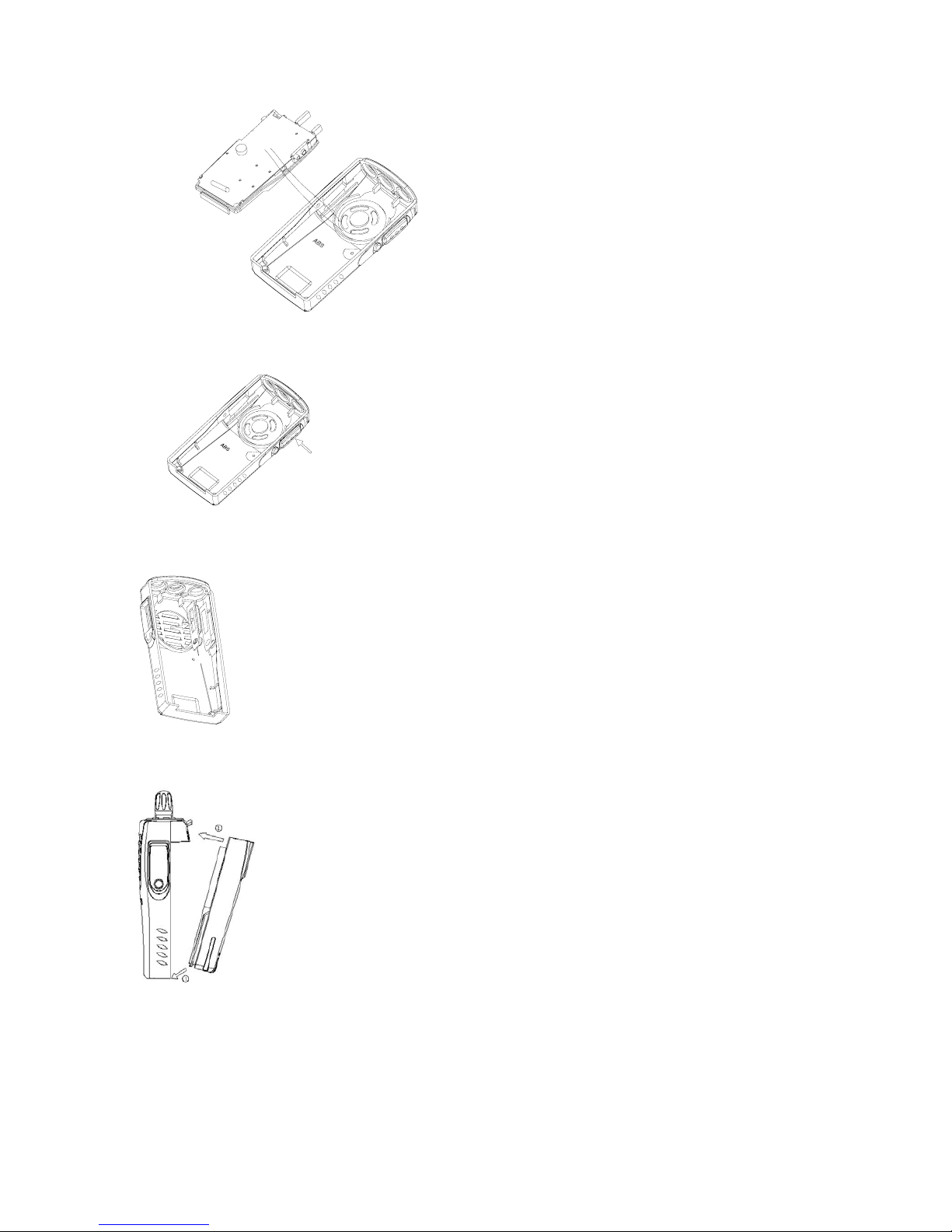
Put down the PTT button
Pull out the PTT button from the front cover.
Put on the PTT button
Put the double glue on the front cover.
Then push the PTT button into the hole which in the front cover.
Put on the battery
Put the base of the battery to the radio aluminum hull rabbet and push, then press the top
of the battery to the radio until you heart a ”click” sound, it will be OK.
Page 21
21
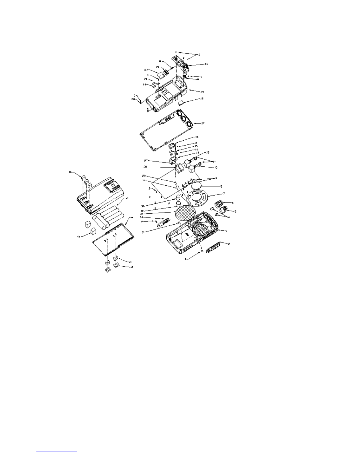
Component plans
Page 22

22
FCC Compliance
This equipment has been tested and found to comply with the limits for a Class B digital
device, pursuant to part 90 of the FCC Rules. These limits are designed to provide reasonable
protection against harmful interference in a residential installation. This equipment generates,
uses and can radiate radio frequency energy and, if not installed and used in accordance with
the instructions, may cause harmful interference to radio communications. However, there is
no guarantee that interference will not occur in a particular installation. If this equipment does
cause harmful interference to radio or television reception, which can be determined by
turning the equipment off and on, the user is encouraged to try to correct the interference by
one or more of the following measures:
· Reorient or relocate the receiving antenna.
· Increase the separation between the equipment and receiver.
· Connect the equipment into an outlet on a circuit different from that to which the
receiver is connected.
· Consult the dealer or an experienced radio/TV technician for help.
Modifications not authorized by the manufacturer may void users authority to operate this device.
FCC Licensing Requirements
Your radio must be properly licensed Federal Communications Commission prior to use.
Your dealer can assist you in meeting these requirements. Your dealer will program each
radio with your authorized frequencies, signaling codes, etc., and will be there to meet your
communications needs as your system expands.
Safety:
It is important that the operator is aware of and understands hazards common to the
operation of any radio.
READ THIS IMPORTANT INFORMATION ON SAFE AND EFFICIENT OPERATION.
The EUT is Face-held only, not allow to body-worn configuration, the safety distance should be at least
2.5 cm.
 Loading...