

Tekin Power Flex BC 112A, Power Flex BC 112C Owner's Manual
OWNER’S MANUAL
BC 112A & 112C
Power Flex
™
Chargers
with Ni-Cd and Ni-MH capability
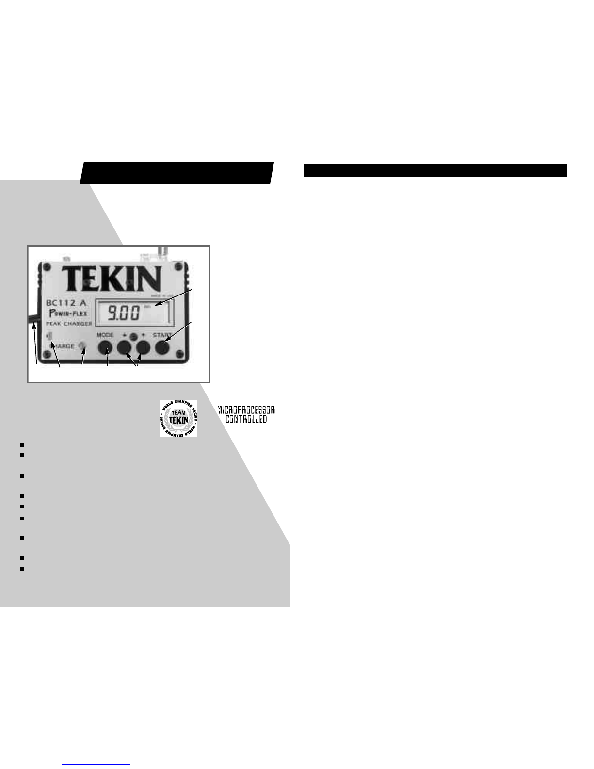
A) Digital Display
with
Annunciators
B) Charge Start
Button
C) Set Buttons
D) Mode Select
Button
E) Indicator LED
F) Output LED
G) Output Cable
Accepts 10-24 volts DC (both models) or household AC input (112C only).
Uses TEKIN’s exclusive high-performance Power-Flextm Negative Pulse
battery conditioner circuit.
Microprocessor controlled optimized charge profiles, and custom
multi-function LCD display with annunciators.
0 to 10 amp linear charge output with adjustable trickle charge.
Dual 12 bit high-precision analog to digital converters.
33 kHz high-frequency switch mode power supply for cool, efficient
operation under all conditions.
Proprietary Adaptive Sensing peak detection monitors the charge profile
and detects the correct optimum shut-off point for maximum accuracy.
Compact, dependable, lightweight construction.
Expandable to a complete charge/discharge-matching and test system.
MADE IN THE USA
T E K I N
ELECTRONICS, INC.
G F E D C
A
B
TA BL E OF CO NT EN TS
Power Source Selection .......................................... 1
AC Power Source ...................................................... 1,2
Fuse ........................................................................... 2
Power-Flex Circuit ....................................................... 2
Connecting the Battery Pack .................................... 2
Charger Settings and Display Modes ..................... 3
Display Profiles ............................................ 3,4
Set Modes ....................................................... 4
Start Button and Charge Profiles .............................. 5
Charge Profiles ............................................. 5
Timed Charge ................................................. 6
Selecting the Charge Amperage
Fast Charging ................................................ 6
Trickle Charging ............................................. 6
Miscellaneous Tips and Tricks ................................ 7
Charging ........................................................ 7
Discharging ................................................... 7
Optional Add/On Discharger ...................... 7
Troubleshooting ....................................................... 8
Error Codes ................................................. 8
About Tekin .............................................................. 9
Limited Warranty ..................................................... 9
TEKIN, BC112, Power-Flex, Slope Detector, Slope Detection, and Pro-Flex are trademarks of Tekin
Electronics, Inc.
- Copyright 1999 Tekin Electronics, Inc., All Rights Reserved-

The BC 112 series charger’s can use virtually any power source that puts out
between 10 and 24 volts DC, with a current rating recommended of 4 amps or higher.
You can use a regulated supply or lead-acid battery. The power supply voltage should
be equal to or greater than the peak voltage to which you wish to charge your batteries. 12 volt supply is a sufficient to fast charge 7 cells. Up to 12 cells in series can be
fast charged with an input of 24 volts. If the power source output current is not rated
for at least 50% of the charge current set on the BC 112, the charge will terminate early.
Caution: If you use a lead-acid (automotive) battery as the power source, make sure
you have good ventilation. Lead-acid batteries generate explosive hydrogen gas when
they are being charged. Do not charge a lead-acid battery anytime a TEKIN charger
is also connected to it.
The BC 112 has an internal high-frequency, ripple-free buck switch mode power
supply converter which steps down the supply voltage down to whatever is needed by
the battery pack. This allows you to use a strong power supply input without causing
the charger to get excessively warm. When the voltage is stepped down, the amperage is stepped up. For this reason, an amp meter on your power supply may read
lower than the actual charge amperage. Use the meter on the charger for an accurate
reading of the charge current.
Connection: Once you have selected a suitable power source, connect the large RED
positive(+) clip of black input cable to the POS (+) terminal of the power source, and
the large BLACK negative (-) clip to the NEG (-) terminal of the power source The
heavy black input power cable of the charger plugs into the connector on the back of
the charger.
Warning: Improper or unsafe use of this or any other AC powered device can be hazardous. Do not operate or plug in the unit near water or moisture. Not for use outdoors,
except under dry, controlled conditions. Always unplug the charger when not in use. If
the AC power cord becomes frayed, worn, burned, or damaged in any way, you should
immediately shut off the power at the breaker box then unplug the unit from the AC outlet. Adamaged charger should not be used until it is properly repaired. Do not attempt
to open or repair the charger yourself. Never insert objects into the cooling vents on
the charger.
The BC 112C has a built-in 120 VAC power supply which will charge 1 to 12 cells
to a full peak at up to 10 amps. When using AC, first unplug the DC power cord from
the back of the charger. This will keep the clips from accidentally shorting and blowing
the fuse. Plug the AC power cord from the charger into any suitable wall outlet. Be sure
to keep soldering irons and sharp objects away from the power cord.
The BC 112C is available for use with different AC voltages. The standard voltage
is 120 volts for the USA. If your charger is intended for use with voltage other than 120,
it will have a tag attached to its power cord indicating so. In this case, use only the voltage specified on the tag. The BC 112C is designed, however, to work properly
on 220-240 volts when marked 240.
-1-
PO WE R S OU RC E SELE CTION
AC PO WE R SO URCE (M od el BC 1 12 C on ly )
The BC112C’s 24V output insures plenty of power is available to fully charge your
batteries, even with low AC line conditions.
You may use a second Tekin charger plugged in to the extra power plug on the
back of the BC112C. Use only a charger rated for 24 volts input, such as a BC112A or
BC110L. This will allow you to use 2 chargers from the same power supply. When doing
this, it is recommended that you set both chargers to a total current of 10 amps or less
(5 amps on each charger, for example.) If you operate the charger at over 120 watts
total output, the power supply may become excessively warm and shut down for a few
minutes until it cools. This is usually not a problem when charging 7 cells or less. If
shutdown does occur, a small fan may be used to help keep the internal power supply
cool, or you may reduce the charge amp rate. The power supply will come back on in
a few minutes.
If an overload occurs or improper connection is made, the fuse will blow. In this
case, disconnect the power and remove the fuse by pulling it straight out. Then
replace it with a 20 amp automotive style plug-in fuse (model 112Auses two fuses). Do
not use a fuse rated higher than 20 amps, or the charger could become damaged.
Normally a cell will noticeably begin to lose its edge and crispness to throttle a
response after just a few hard runs. This is caused by a gradual buildup of impurity and
crystal formation inside the cell, which is unavoidable, and increases the cell resistance. With each run the impurities increase, resulting in increasing internal resistance,
and therefore reduced voltage and power output. Discharging the battery fully after
each run will help reduce this to a certain extent, but the only way to totally minimize
this deterioration, and even actually reverse any previous deterioration, is to use the
TEKIN Power-Flex process. Power-Flex technology, which Tekin introduced, makes
your batteries perform like no other charge process can, and increases horsepower
beyond what even a new fresh cell can deliver.
The Power-Flex works by periodically turning off the charge current, and applying a
short-duration, high-amperage discharge pulse of negative current to the battery. This
“burping” effect acts to relieve the pressure buildup which occurs inside a cell during
charging, and to restore its chemical balance. It also improves the plate surface structure, for better power transfer. The net result is that the cell stays cooler during the
charging process, and delivers more voltage and capacity under a load, with lower
resistance. There are three user-adjustable levels of conditioning. Additionally, the
computer makes adjustments as required.
The BC112 has a factory installed Tamiya-style JST connector. If this is the type of
connector used on your batteries then just unplug the clip leads from the charger and
plug the battery pack right in. For other plug types, you may wish to install a mating
connector on the charger. If you use the alligator clips, you should solder some stub
wire leads onto the battery pack and clip onto them. The alligator clips should be
clipped onto soft, multi-strand wire to insure that a good connection(s) is made. A poor
connection can cause the charger to “false peak” and turn off before the charge is completed.
Please note: Kyosho-style packs use the same JST connectors as Tamiya, but may be
wired in reverse from that of the charger. Please be sure the positive (+,red) and the
negative (-,black) wires are matched with the red and black wires on the charger.
-2-
F U S E
PO WE R- FL EX CI RC UI T
CO NN EC TI NG THE BA TT ER Y P AC K
 Loading...