

Tekin B1, B1-R Owner's Manual
NOTE: Before Radio Calibrating, ensure speed control is
hooke d up to the recei ver, a charge d battery i s properly co nnected, and the transmitter is turned on. On your radio, set all
trim adjustments to the middle, throttle/brake EPAs set to max
and ensure that your throttle directio n is set to “normal” .
Calibrat ion is real ly very si mple, you j ust press and hold the
MODE butto n for 3 sec onds to e nter radio calibrate , let the
speed co ntrol “find” yo ur neutral , then let i t “find” your ful l
thrott le and full br ake. If yo u are unsure how to pe rform this
procedure, follow the detailed steps outlined below.
Congratul ations on your purchase of the B1/B1-R, Tekin’s
High Perf ormance Mini Brushed Motor Electronic Speed Control. The QuickTune
feat ure allows t he user to quickly and
accurately adjust all critical operating parameters. Just connect
the spee d control as described be low, perfor m a quick radio
calibr ate, and you are ready to race!
B1
Forward / Brake
PROFESSIONAL MINI B RUSHED SPEED CONTROL
• Adjustable Drag Brake/Reverse Type
• Voltage Cutoff for LiPo Cells
• Push ( Anti-Drag Braking )
• QuickTune Digital Setup
• Temperature Monitor
OWNER’S MANUAL
INTRODU CTION
The fo llowing stat ements nee d to be under stood befo re using
the B1/B1-R:
1. Turn on the transmitter first to avoid uncontrollable noise
to speed control.
2. Dis connect batt ery from s peed control when not in use .
3. Do no t hook-up the battery backw ards! No re verse voltage prot ection.
4. Do no t operate s peed contro l in or around wat er.
5. Insul ate expose d wires wit h heat shr ink tubing to prevent
short circuits.
6. The B1/B1R is intended f or Mini vehic les only.
SOLDERING
IMPORT ANT: Use extreme care and observe proper safety
precaut ions when so ldering. Al ways wear e ye protect ion. Be
sure t hat both wires are disconnec ted from the battery befo re
soldering on the posts.
Never keep a hot soldering iron on the speed control solder
posts fo r more than 3 seconds—the sol der post may beco me
de-sol dered from the spee d control and beco me damaged.
HINT: It should only take a few seconds to solder the wire to
the post. If you do not complete the solder joint in approximately 3 seconds, remove the iron, clean and tin the tip, then
repeat the procedure below. Applying a small amo unt of sol der
paste f lux can oft en help so lder flow on a st ubborn sur face.
SOLDERING CONT...
ATTACHING WIRES TO THE SPEED CONTROL:
1) Red Wire s are usual ly used to connect the speed co ntrol
to the positive battery terminal and the positive motor
terminal . Black wire is typic ally used for t he batter y
negative t erminal , and blue is used for the negat ive motor
connection. Inspect the sticker on the speed control or
refer to the diagrams to determine which color wire to
attach to each post.
2) Strip back the insulation of the wire by about 3/32” to
1/8” and “pr e-tin” t he wire by heat ing the end and a pplying sol der until it i s thoroughly c overed. You may s hake
of any excess solder while it is still hot. Be very careful
not to splash yourself with hot solder.
3) If there is no solder on the post, place the tip of the iron in
the notc h on top of t he post and apply a small amount of
solder to the post. When the solder has flowed, remove
the sol dering iro n, wipe the t ip clean and apply a smal l
amount o f fresh sol der to it.
4) Hold t he wire so the tinned e nd is in co ntact with the
notch of the post . Now touch the iron ti p to the wir e and
the post. Wait about 2 seconds for the solder to flow, and
then remove the iron while still holding the wire. You
may let go of the wire after a s econd or two when the
solder sets.
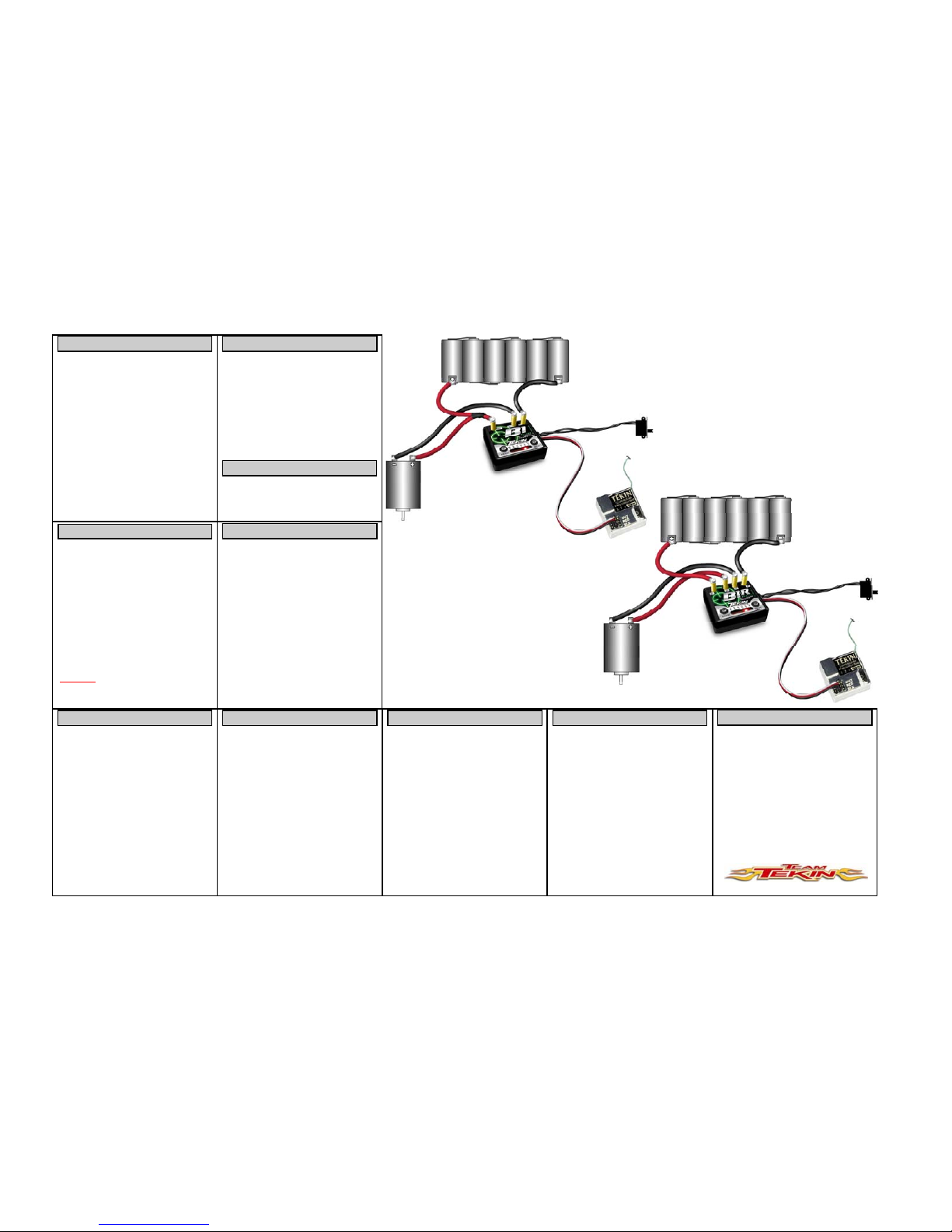
Fo r B1 C onne ctio n Diag ram, Ref er to Fig ure 2 ,
For B1R Connection Diagram, Use Figure 3.
1) Placement : Choose a l ocation for the spee d control that is
protect ed from de bris. HINT: To pre vent radio i nterference place the speed control as far away from the radio
receiver as possible and keep the power wires as short as
possibl e. If poss ible plan o n routing power and moto r
wires away from the radio receiver and radio wires.
2) Mounti ng: For best results cle an the bot tom of the s peed
control and chassis . Using the doubled-sided t ape,
(incl uded) mount the speed contr ol to chassis .
3) Using a sm all piece of double-side d tape, mount the ON/
OFF switch in a convenient place.
4) Determ ine how you would pr efer to co nnect the motor
and batte ry pack to the spee d control. U sing connec tor
pairs i s prefer able for mos t applic ations as i t allows yo u
to e asily switch bat tery pac ks and change motors.
Whether using co nnectors or di rect sol dering, co nsider
where yo ur batter y pack sits and how much wir e will be
needed to attach to the speed control.
HOOKUP INSTRUCTIONS
HOOKUP INSTRUCTIONS CONT...
NOTE: Make sure all wires are secure and a safe distance
from all moving parts—use the zip-ties in the accessory pack.
RADIO CALIBRATION
QuickTune MODES
MODE RANGE DEFAULT
DRAG B RAKE
(DRG B)
1-11 1 (OFF)
NEUTRAL WIDTH
(NW)
1-11 5
CUR REN T LIM ITE R
(LIM)
1-11 11 (OFF)
PUSH CONTROL (ANTI DR AG)
(PC)
1-11 1 (OFF)
REVERSE TYPE—-B1R
(RT)
THROTTLE PROFILES-B1
(TP)
1-3
1-6
3
3
VOL TAGE CUTO FF
(VC)
1-4 1 (NONE)
PRECAUTIONS
DO NOT CONNECT BATTER Y INCORRECTLY TO
SPEED CONTROL, VERIFY THAT THE BATTERY
POSITIVE WIRE WILL CONNECT TO THE SPEED
CONTROL POSITIVE WIRE B EFORE CONNECTING!
1) CONNECT SPEED CONTROL TO RECEIVER
Plug the speed control into the throttle channel of the receiver.
• Channel 1: Servo
• Channel 2: Speed Co ntrol
“REMEMBER: 1 to Turn, 2 to Burn”
3) CONNECT SPEED CONTROL TO MOTOR
Visually verify that the connector on the motor and the speed
control match the chart below, then connect.
Startup Se quence
When the po wer switc h is turned ON t he speed contr ol begins
looking f or the neut ral signal. If a neutral si gnal is found t he
Arming Seque nce (fl ashes LEDs /chime) will occur fol lowed by
LED3 on s teady
. NOTE: If Arming Sequence does not occ ur
see Troubl e Shooti ng section of this manual be fore pr oceeding.
One Touch Radi o Calibratio n
1) Turn on transmitter.
2) Turn on speed control.
3) Press and ho ld the M ODE button o n the spee d control for
3 seconds. All LEDs will blink red 3 times with 3 chimes.
The spee d control will make a pulsi ng chime as i t looks
for a neut ral signal— you do not need to do anything ye t.
4) When NEUTR AL positio n is found and r ecor ded, LED3
will fl ash and a confi rmation chi me will so und .
5) The puls ing chime wil l begin agai n and LED6 will flas h;
pull tr ansmitter t rigger to the full t hrottle posi tion and
hold unti l the confi rmation chi me sounds.
6) The puls ing chime wil l begin agai n and LED1 will flas h;
push trans mitter tr igger to the f ull brake pos ition and hold
until t he confirmat ion chime sounds .
7) Release trigger to return to neutral position. LEDs will
flash and t he arming se quence chi me will sound.
8) LED3 is now on steady. C alibrati on is co mplete and you
are ready t o drive!
NOTE: If any pro blems occu r, repeat r adio calibrat ion.
HINT: Once calibrated, the LEDs on the speed control will
advance as the t hrottle or brake is appl ied.
Hairpin Trigger Response: If you wish to have a very sho rt
trigger range, the n only sque eze the thro ttle/br ake trigger
partial ly during the radio calibr ation proce dure. Throttl e/Brake
response will not be quite as smooth, but yo u can pull full
throttle very quickly.
QuickTune :
1) Press the MODE button to access the desired setup mode.
The LED starts blinking to indicate that mode selection is
under way. Each time t he MODE butto n is pressed and
released, the LED advances. For example, to get to the
Voltage Cutoff adjus tment, si mply press and releas e the
MODE button 6 times. NOTE: Do not wait longer than
5 seconds to adjust the selected MODE or the speed control wil l return to normal ope ration.
2) Press and release the INCR button to adjust the value.
The first time INCR button is pressed, the LED(s) will
display the existing setting. Each time the INCR button is
pressed the value will advance, then after maximum, start
over again at the low end of the scale. If two LEDs are
on at once, it indicates a value mid-way between the
LEDs.
QuickTune Exam ple: Let ’s say you want t o use a 2 cell LiPo
battery. To change the Voltage Cutoff from the default setting
(1 = None) to setting 2 (2 = 6.0 Volt Cutoff), first follow step 1
above by pr essing and r eleasi ng the MODE but ton 6 tim es.
Now press and release the INC button, the LED should show
the curr ent setti ng of 1. Press and release the INC button agai n
and the LED will move to position 2, indicating that Voltage
Cutoff is now set to 6.0 Volts. Wait 5 seconds and the ESC
returns to normal operation.
HINT: If you wis h to set a nother Pro gram Feat ure, press the
MODE butto n again. After 5 seco nds pause, the values yo u
selected will be saved in memory and the speed control will
resume normal oper ation.
PIT TU NING : If you are in the pit area and cannot use your
transmi tter you may us e pit t uning mode t o adjust set tings by
following t his proce dure: Unplug t he steeri ng servo from the
receiver to avoid servo damage. Hold down either MODE or
INCR button while turning the power switch on. An LED sequence will occur indicating yo u are in pi t tune mode . The
user set tings will be active, but the moto r will no t run and the
speed control will not respond to receiver signals. Turn the
speed control powe r off and bac k on to r esume normal operation.
LED1: DRAG BRAKE contro l provides i mmediate br aking
action i n the neut ral zone. This gently slows the c ar down
when you l et off t he trigger . Drag Brake can provide a better
cornering approach . Higher values increase the degree of drag
braking.
QuickTune
Tekin’s Quic kTune electronic setup feature allows users to
change every critical operating parameter in a quick, easy, and
accur ate fashion. The basic oper ation is des cribed as :
• Use MOD E button to sc roll to a P rogram Feat ure.
• Use INCR ( increment ) button to view/adjust the Feature .
The B1 series has a built-in se lf-test mode that chec ks all major
systems on the spee d control. Bef ore using the self-test mo de,
be sure the rear whee ls are free to spin (off the ground) . To
activate the self-test, turn the speed control on, then press and
hold bot h MODE and INCR but tons simul taneously fo r 5
seconds . After 5 seconds, t he LEDs will ramp up in se ts of
two. Circuits inside the speed control are tested to see if any
proble ms have occ urred. If t he unit pass es self- test, the n LED3
wil l st ay on s tea dy.
If probl ems occur turn the po wer off to the unit and verify all
other co nnections are clean/ tight/cor rect (moto r, receiver, battery, plugs, etc) . After veri fication, po wer the unit back on.
NOTE: Activating the self-test mode also resets all the userprogram mable setti ngs and paramet ers to their defaul t values.
The use r’s radio cal ibration set tings are also reset to de faults.
SELF TEST
B1-R
Forward / Brake /
Reverse
ESC MOTOR
(M -) Blue Wire (-) Negative
(M +) Red Wire (+) Positive
2) CONNECT SPEED CONTROL TO BATTERY
Visually verify that the connector on the battery pack and the
speed control match the chart below., then connect.
DANGER: If the batter y wires to uch during the plug inst alla-
tion. It will cause an electrical short circuit resulting in damage
to the pack and poss ibly a fire hazar d. Tekin re commends t he
use of hi gh quality bat tery c onnectors, such as De an’s Plugs , to
impro ve power tr ansfer and minim ize the risk of shor t-circuit s.
ESC BATTERY
(B-) Black Wire (-) Negative
(B +) Red Wire (+) Positive
Pit Tune Mode
SPEED CONTROL SPECIFICATIONS
Controls , B1 Fwd/Brk
Input Power (Cells)
4-8 NiCd/NiMh
2-3S LiPo
Motor Limit Size 370 Si ze or smaller
Motor Limit Turns None
ON Resistance
B1
B1-R
0.0013 Ohms
0.0052 Ohms
Max Current
B1
B1-R
60 Amps
30 Amps
BEC 5 Volts, 1.5 Amps
Power Wires 16 GA Silicone
Dimensions 1.0 x 0.9 x 0.25 In.
(25.4 x 23 x 6.3 m m)
Weight (with wires) 0.28 Oz ( 8g)
Controls , B1-R Fwd/ Brk/Rev
The fo llowing ite ms are need ed to conne ct your s peed control:
• Soldering Iron
• 60/40 Electric Grade Solder (or silver solder)
• 4 pieces 16 Ga. Wire ( Included)
• Motor/B attery conne ctors (2 pair)
MOUNTING
SOLDERING, TOOLS NEEDED
SOLDERING CON T...
ATTACHING WIRES TO THE BATTERY:
The same techniques describe d in the prece ding sectio n may be
used to solder the wires to the battery connectors.
IMPORT ANT:
Take pr ecautio ns if removing f actor y battery
connec tors. Conne cting the bat tery backwar ds will c ause damage, and will void warranty. When s older ing connect ors to a
battery pack, cut only one wire of the battery pack at a time to
ensure that the expos ed wires canno t short to gether.
HINT: If you are using Dean’s connecto rs for both t he battery
and the mo tor, make sure that you have a mal e and a fe male
attache d to the spee d control wi res. That way, yo u cannot ac cidentall y connect the batter y to the mot or wires or vice ver sa.
1) If using a c onnector between batte ry and spee d control
make sure that the ends will be mat ed together correctly,
male t o female, and t hat the wir e colors match—red t o
red and blac k to black.
2) Solder the wires from the speed control to each of the
connectors, then solder wires from the battery to each
connector’s mate.
ATTACHING WIRES TO THE MOTOR:
The same t echniques described i n section 5 may be used to
solder the wires to the motor.
1) If using a c onnecto r between mo tor and spe ed control
make sure that the ends will be mate d together correctly,
male to female, and that the wire colors match—red to
red and blue to blue.
2) Solder the wires from the speed control to each of the
connectors, then solder wires from the motor to each
connector’s mate.
REMOVING WIRES:
1) Have a ho t iro n and the spe ed contro l secured. Cl ean the
tip of the iron and ap ply a small amount o f solde r. While
the tip is still smoking from the flux in the solder, touch
the tip of the iron to the top of the post.
2) As the so lder on the po st melts, pul l on the wire you wish
to remove.
HINT: If there is excess solder remaining on the post, you
may remo ve it by heat ing the po st until the solder j ust start s to
melt, then quickly tappi ng the spee d control agai nst the
workbench to knock off the exces s solder .
SOLDERING CON T...
Listed be low are a number o f tips to ensure t hat you will get
years of trouble- free perfor mance from yo ur Tekin spe ed
control.
LED2: NEUTRAL WIDTH adjusts your deadband a round
the neu tral point . A low neutr al width value pro vides more
sensit ive trigger response ar ound neutr al.
LED3: CURRENT LIMITER adjusts the throttle response
during acceleration to control annoying wheelspin. Low values
allow low amounts of current to pass to the motor, higher values allo w higher amount s of cur rent. The top value (11) turns
OFF current limit.
LED4: PUSH CONTROL or ANTI-DRAG BRAKING
overcomes the natural drag of the motor when you return to
neutral. Racers refer to this as “creep” , this setting eliminates
the need to trim the throttle forward to create a coasting
(pushing) effect . Low values give you a shor t duration pus h,
higher value s a longe r duratio n push
LED5: BRAKE/REVERSE TYPE ** B1R ONLY**
1) Proportional Brake with Reverse Lockout (LED1 ON).
Propor tional brake will be applied dur ing rever se throt tle.
2) Forward to Brake to Reverse (LED1-2 ON). The car will
operate freely in forward and reverse. (Brakes to a stop
before switching into reverse)..
3) Proportional Brake with Reverse Delay (LED1-3 ON).
The car will only go in reverse if the trigger has been in
neutral for 1 second, otherwise it operates like
proportional brake with no revers e.
NO LIGHTS COME ON
Check f or dead batte ries. Chec k the connec tions bet ween the
batteries and the speed controller and that the switch is in the
“ON” position. Verify that there are no bad connections at the
spee d controller . Check fo r reverse battery co nnection.
ALL L EDs F LASH ING
No radio signal can be found. Chec k recei ver connect ion and
verify t hat ESC is plugged int o corre ct channel . Verify t ransmitter and recei ver are functi oning pro perly.
BOTTOM OR TOP 3 LEDs FL ASHING
Radio s ignal fo und, but neutr al point from trans mitter is out of
expec ted range. Spee d control not calibr ated properl y or radio
setti ngs have been c hanged. Rec alibrate speed cont rol as describe d in the R adio Cali bration sect ion.
ADJUSTMENT MODES CONT...
Before se nding your B1 /B1-R in fo r service , please revie w the
Instruc tions and Tro ubleshoo ting sectio ns. After reviewing
these i nstructions , if your s peed control still requi res service ,
please contact our customer service department for additional
assistance. To obtain the most current product service options
and pricing, consult the following:
WEBSITE: (www.teamtekin.com) Follow the instructions
from the Service Re quest sectio n of our webs ite.
PHONE/FAX: Contact our customer service department.
WARRANTY SERVICE: For warranty work, you MUST
CLAIM WARRANTY on A COMP LETELY FILLED OUT
PRODUCT SERVICE FORM and include a VALID CASH
REGISTER RECE IPT with pur chase dat e, deale r name &
phone# on it, or an i nvoice fro m previous ser vice. If warr anty
provisions have been voided, there will be service charges.
NOTE: Hobby de alers or distri butors are not authorize d to
replace TEKIN produc ts thought t o be defec tive.
Tekin, Inc.
McCall, Idaho
(208) 634-5559 / (208) 634-5 569 (FAX)
www.teamt ekin.co m
WARRANTY
TEKIN, INC. guarantees speed controllers to be free from factory def ects in mat erials and wor kmanship fo r a perio d of 120
days fro m date of pur chase, when verifie d by sales receipt. This warranty do es not co ver: suitabi lity for specific
applicat ion, co mponents wo rn by use o r improper voltage,
tamper ing, misuse, or shipping. O ur warranty l iabilit y shall be
limite d to repairi ng unit to our original specific ations. Bec ause
we have no control over the installation or use of this product,
in no cas e shall we be liable fo r damages.
Additionally, these items void the warranty:
1) Using the same polarity connectors on the battery and
motor wires from the speed controller.
2) Allowing water or moisture into the speed controller.
3) Incorrect wiring.
4) Use inconsistent with the instructions.
OPERATING TIPS
LED5: THROTTLE PROFILES ** B1 ONLY**
1) Mildest profile, concave (LED1 ON)
2) Mild pr ofile, co ncave (LED1- LED2 ON)
3) Line ar profi le (LED1- LED3 ON)
4) Aggressive profile convex (LED1-LED4 ON)
5) More aggressive profile, convex (LED1-LED5 ON)
6) Custom— User Adjustable Using Tekin HotWire PC
Connectio n (LED1-LED6 ON).
LED6: VOLTAGE CUTOFF
1) NONE (LED1 ON)
NiCd/NiMh Cells.
2) 6 Volts (LED1-LED2 ON)
2 Cells LiPo (2S)
3) 9 Volts (LED1-LED3 ON)
3 Cells LiPo (3S)
4) Custom (LED1-LED4 ON)
User Adjus table Cuto ff, requi res Tekin Ho tWire PC
Connection.
IMPORT ANT:
If us ing Lithium Polymer (LiPo) bat teries, DO
NOT operate your vehicle with the factory default Cutoff Voltage sett ing (None) .
PROPER ON/OFF PROCEDURE
Always turn your transmitter on first and then turn on your
speed co ntrol. At the conclus ion of your r un, simply re verse
the above procedure.
BATTERY POLARITY
It is e xtremely im portant to e nsure the bat tery pack i s
connec ted to the s peed contro l properly. Connecting t hem
backwards could ca use severe damage to the battery pack and/
or speed control.
DO NOT JAM THROTTLE
This will cause tre mendous reduc tion in run t ime and exce ssive
heat buil d-up.
RADIO INTERFERENCE
Try to kee p the rece iver at l east 1-2 inc hes away fro m any motor or battery wires.
RECEIVER BATTERY
The built -in BEC (Bat tery Eli minator Ci rcuit) is str ong enough
for 1 st andard ser vo. If you are us ing a high po wer ser vo you
may need a s eparate r eceiver bat tery (see Receiver Bat tery
section).
NO REVERSE
QuickTune mode, Brake /Reverse Type is set to option 1.
QuickTune mode, Brake /Reverse Type is set to option 3
(trans mitter tr igger must be in neutr al posit ion for 1 s econd
before reverse is enabled). Speed control is a B1, not a B1R
(not a reversing type).
MOTOR WILL NOT SHUT OFF OR RUNS SLOWLY
Incor rect radio calibratio n or thro ttle trim se tting on t ransmitter. Check tr ansmitter settings and recal ibrate s peed contro l.
Moisture in speed control: Unhook batteries and let the speed
control dry.
MOTOR CUT OUT/RADIO INTERFERENCE /POOR
RANGE
Transmit ter batte ries are low or damaged. M ismatc hed crystals. The three-wire cable from speed control to receiver may
also be too long; 6 inc hes is t he maximum. Thi s speed co ntrol
radiate s very lo w noise and you sho uld have no t rouble with
interf erence. If you do have inte rferenc e, mount the speed
control in the pan, and mount the receiver and antenna at the
top of the shock tower. Try to keep the receiver away from the
batteries, power wires, metal or graphite.
TROUBLESHOOTING
NOTE: Optio nal. Connec t a separate battery pac k to the
receiver using the “B” or “BAT” socket on your receiver. A
small switch should be used on the receiver pack to operate the
radio., and the receiver pack should have no more than 5 cells.
IMPORTANT: You must remove the red wire from the speed
control servo plug an d cover it with heat shr ink tubing.
The On-Bo ard Temperat ure Monito r works to provide you with
important feedback o n speed co ntrol tem perature, he lping you
to adjus t gearing and avoid long t erm heat damage. To us e;
1) The spe ed control must be c alibrated to your radio and
the radi o must be in the ne utral posit ion.
2) The middl e LED will be on st eady, and sho uld blink ou t
every 2 seconds.
3) At the moment that the center LED blinks out, one or
more of the other LED s will ligh t up.
4) LEDs 1-3 lit is typi cal of li ght loads or a s tock motor .
LEDs 1-5 lit indi cates he avy loads and i s typic al when
running mo d motors. LEDs 1-6 li t indicates hi gh inter nal
temper atures appro aching the rmal shutdo wn. Disco ntinue us e until the speed cont rol return s to normal o perating temperature.
SERVO WORKS, THROTTLE DE AD
Speed co ntrol not adjusted corr ectly. May be i n Pit Tune
mode. If LEDs are fl ickering, may i ndicate that Volt age Cutoff
is set above battery pack voltage. Check that cutoff is correctl y set and that battery i s fully char ged. Motor or connections to motor are bad. Receiver plug or connections are bad.
Speed c ontrol no t plugged in to thrott le channel o n receiver .
STUTTERING UNDER HE AVY ACCELERATION
Recei ver is getti ng magneti c field interfere nce. Try mount ing
receiver on its side and/or spacing it 3/16 inch up from the
chassis . If this doe s not work, t ry mounti ng it on its other side.
Move power wires away from receiver. Check for low current
limiter setting. Check for incorrect Voltage Cutoff setting.
BRAKES DO NOT WORK AT ALL
Speed control or radio transmitter improperly adjusted. Adjust
EPAs on transmitter all the way out and recalibrate speed control to radio.
AUTO COU NT NO T WO RKI NG
Mount t ransponder at front of car away fro m batterie s and
wir es .
SERVO AND THROTTLE DEAD
Check f or dead batt eries, bad c onnec tions to s peed cont rol,
dad rece iver plug c onnectio n. Switch may nee d replaci ng.
Broke n wires, bad crys tal, bad radi o equipme nt.
THROTTLE WORKS, SERVO DE AD
Broke n servo. Wiri ng of plug is bad or incor rectly wir ed.
TEMPERATUREE MONITOR
TROUBLESHOOTING CONT... SERVICE AND REPAIR
Figure 2.
B1 Connection Diagram
TROUBLESHOOTING CONT...
ADJUSTMENT MODES CONT...
Figure 3.
B1R Connection Diagram
RECEIVER BATTERY
 Loading...