

Tekelek Europe 687 User Manual
Installation Instructions
Tank Alert
Ultrasonic Liquid Level Monitor
TankAlert monitors and displays liquid levels and
gives an alert when the level drops below 5% of
tank height. There are 2 product
types (1) Transmitter (no display
- 2 versions as in diagrams
above) + Receiver and (2)
Transmitter with Visual display
(allows user to view liquid level
at tank) + Receiver; please follow
the installation instructions for the correct type.
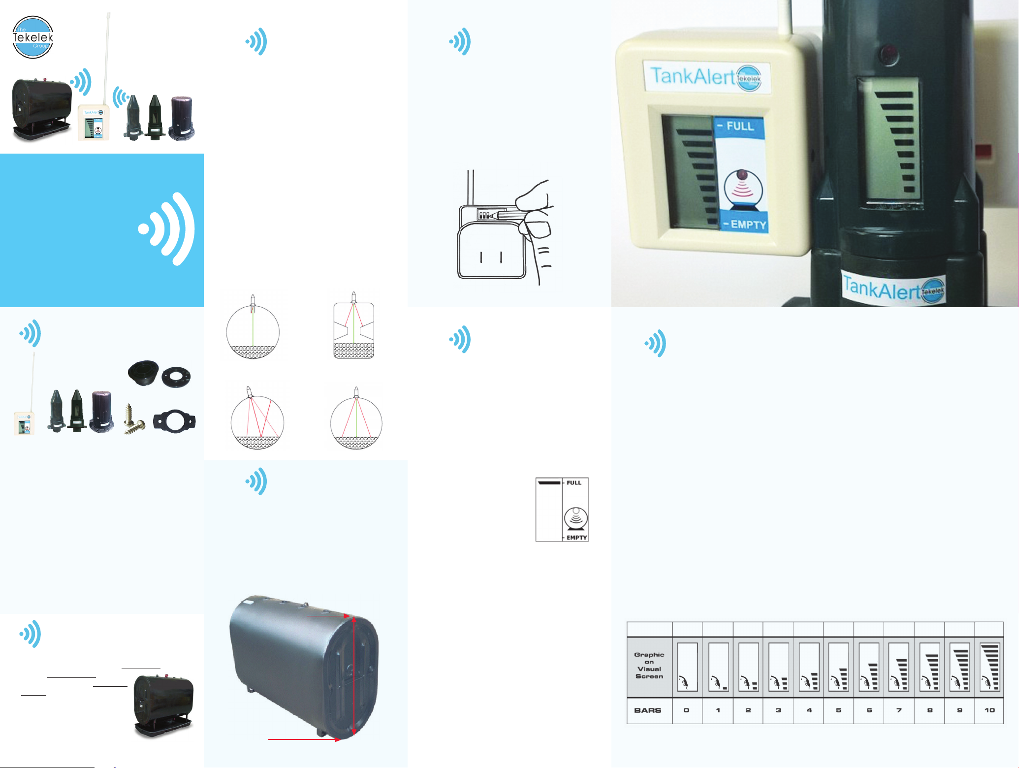
Preparing the Tank1
a) To avoid error, the TankAlert transmitter must
sit in a vertical position on top of the tank and
have a direct line of sight to the liquid level in
the tank, through to the bottom without any
interference from e.g. window configurations or
tank braces.
b) Install the supplied metal adapter into the
pre-drilled 2” NPT opening on the top of the
tank. Apply pipe sealant on the adapter thread
and tighten appropriately. For basement tanks,
temporarily place a rag/cover over the adapter
to minimize fuel odors until transmitter is
synchronized. Tanks with 1½” and 1¼” NPT
openings or European style double-wall tanks
require adapters. Do not use an extension pipe
when mounting the adapter; this can cause
inaccurate measurement and malfunction.
c) Installation Help:
Avoid tank braces and tank windows.
7 7
3
Setting the
Switches on
the Receiver
Activate the switch (located at back of receiver)
numbers that correlate to your tank size (see
chart at Step 9 overleaf) by using a screwdriver or
ballpoint pen to move the switches upwards to the
ON position. Activating switch 1 (the audible ring
feature), enables a bleep to indicate a low-level
reading (< 5% liquid warning).
Contents of Pack
C
A
B
D E
A Receiver
B Transmitter (Visual or no display)
C Mounting Adapter
D Screws
E Weather Seal
Fuel & Tank Types
TankAlert can be used on all standard steel tanks. To work
optimally, tanks must be placed on a level surface, be a
maximum height of 10 feet and be within
a 450 ft./150-meter line of sight of the
receiver.
Position Tank on
a Level Surface
7 3
Define Tank Height2
Accurately measure the height of your tank from
the liquid outlet at the bottom of your tank to the
bottom of the TankAlert ultrasonic monitor. TankAlert
measures the level of usable liquid in the tank in 10
graduations of the tank height. Correct tank height
measurement is critical for accurate liquid level
display.
Fill Point
1000mm
Bottom of Tank
4
Matching Receiver
and Transmitter for
both visual and
no-display types.
You can now link/match the receiver to the
transmitter, through getting a unique code for your
tank (this need only be done once, at installation).
• Plug receiver into a convenient electrical socket
and switch on.
• The display screen on the
front of the receiver will show
a flashing top bar as shown in
diagram (opposite) for up to
2 minutes indicating that the
transmitter can be matched to
the receiver during this time.
• Hold the transmitter (left side) against the
receiver’s right side so that the black dots on
each are aligned (for 20 seconds). This allows
the unique code to be transferred. During the
matching process, you will hear an audible beep
from the receiver to indicate matching is in
progress. The number of bars will increase on
the receiver display until all 10 bars are flashing
and an audible beep occurs: this indicates that
the unique code has been transferred. The setup
is now complete for the no-display type only;
the transmitter is now ready to read and transmit
liquid levels and must be placed on the tank
immediately (Step 6).
• If matching visual (LCD display) transmitter, you
MUST continue to hold the two units together
and proceed to the next stage of the matching
process (Step 5 across).
5
Additional Matching Step To Calibrate
Visual Transmitter to Tank Height
(TankAlert Visual ONLY)
When using TankAlert Visual, the visual transmitter
must also be calibrated to the tank dimensions. so
that liquid levels can be read at the tank as well as
in your home.
To do this, you MUST continue to hold the
transmitter and receiver together (via the black
dots) after the ten bars are showing on the
receiver (post Step 4).
Continue to hold the black dots together until the
visual transmitter screen goes blank. A nozzle
icon will flash in 10 seconds, indicating that the
transmitter is in ‘tank height setting’ mode. Continue
to hold as the black bars increase until the number of
black bars, according to the table below, increases to
match the height of the tank measured at step 2.
When the number of bars indicates the correct tank
height, immediately separate the transmitter and the
receiver.
Tank Height
(Inches/mm)
31/800 39/1000 43/1100 47/1200 51/1300 55/1400 67/1700 79/2000 91/2300 102/2600
Wait for a double flash of the red light on the visual
transmitter to indicate that the tank height setting
has been stored in the transmitter. The transmitter
can now be placed on the tank.
There may be one bar more or less displayed on the
visual transmitter display compared to the receiver
display when operational. This is due to the smaller
number of tank height settings that may be selected
with the transmitter screen bars compared with the
receiver switches. The bars in both displays will
accurately reflect the level in the tank.
Note: if the number of bars displayed overruns
the height setting table (below), continue to
hold the black dots together until the screen
returns to blank and the nozzle flashes; re-start
the process again until the correct number of
bars appear.
102/2600 to
116/3000
Fitting Transmitter6
Troubleshooting8
Multi Switch Setting Chart9
For tanks with pre-drilled 32mm hole:
• Remove cap from pre-drilled hole and insert
transmitter, ensuring the weather seal is securely in
place and that transmitter sits vertically.
• Tighten on to the tank with 2 stainless steel
self-tapping screws provided. Do not use longer
screws or over tighten.
For tanks with a 2”, 1½” or 1¼” BSP/NPT
gauge aperture (60mm/48mm/42mm)
• Unscrew any caps from hole; fit adapter
provided by screwing into gauge socket.
• Fit TankAlert to adapter on the tank;
ensure weather seal is in place.
• Tighten on the tank using the screws
supplied. Do not over tighten.
NOTE: Mounting Adapter supplied
must only be used.
7
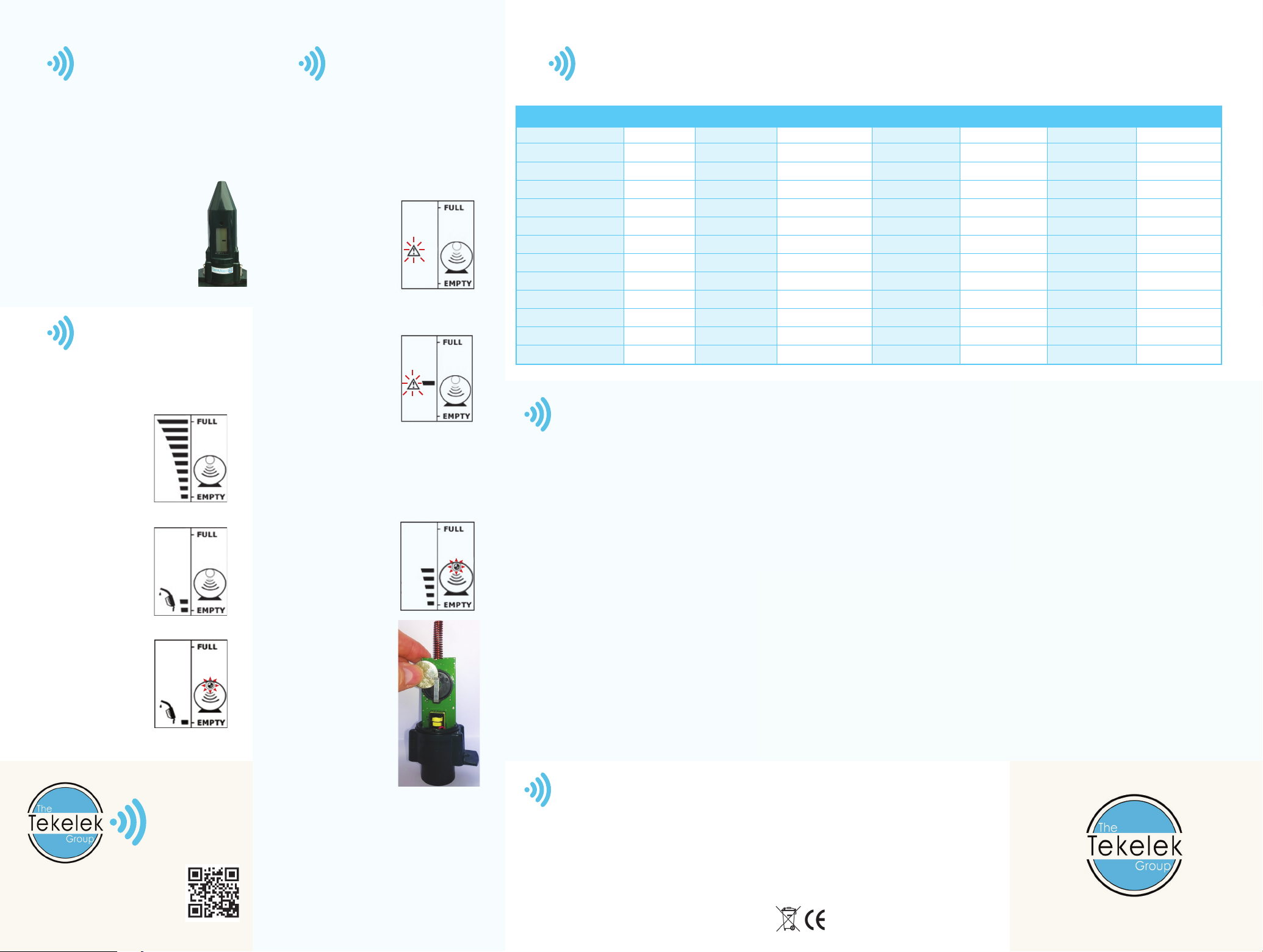
The 10-level bar graph represents the level of liquid
in your tank. The number of bars illuminated denotes
the level of liquid in the tank. You will get 2 re-fill
warnings as shown in the diagrams below.
(a) Full: Note: It may take 1
hour to get the first accurate
reading post installation.
(b) Early Warning (2-bars):
Reading the Liquid Level
Full
Early Warning
(c) Almost Empty (1-bar).
Almost Empty
Support
tekelekgroup.com
info@tekelek.ie
T: +353 (0) 61 471511
a. Power Failure or Receiver Moved
In the event of a power failure or the receiver
being switched off, the receiver display screen
will show a top bar flashing for 2 minutes when
power is restored. The screen will then turn
blank until the unique signal is located (there
is no need to repeat the ‘black dot’ matching
instruction). This could take up to 1 hour.
b. No Transmission Signal
Flashing triangle, no bars,
indicates no signal being
received. This starts
approximately 12 hours
from the last received
good signal. Re-site the
receiver closer to the
transmitter and wait for a
few hours.
c. No Ultrasonic Echo
Flashing triangle, middle
bar only. Check that
the transmitter is fitted
vertically on tank, with
no interference from a
tank wall, corrugation or
window.
If matching is not completed in the 2-minute
interval on plugging in the receiver for the first
time – then turn off the receiver at the power
point and then turn it on again to initiate a new
matching interval.
d. Low Battery Signal:
Constantly Flashing Warning
Light.
1. Remove transmitter from
the tank and take it into a
clean, dry environment.
2. The battery can be
accessed by removing 4
self-tapping screws from
the base of the unit.
3. Remove the old battery
noting the orientation (+
mark facing upwards) and
replace with a new battery
(3V-CR2450)
4. Re-assemble, ensuring
the O-Ring is undamaged
and secured in position.
5. Place the transmitter on the tank.
No need to re-match.
Please consult our website
www.tekelekgroup.com
Measure the vertical height of the tank from the transmitter position on top of the tank to the bottom of the tank. Read to the nearest measurement on the chart.
Tank Height (ins/mm) ‘On’ Switches (ins/mm) ‘On’ Switches (ins/mm) ‘On’ Switches (ins/mm) ‘On’ Switches
20/500 1 45/1150 1,3 71/1800 1,2,8 97/2450 1,2,3,8
22/550 1,7 47/1200 1,3,7,8 73/1850 1,2,7,8 99/2500 1,2,3,6
24/600 1,6,8 49/1250 1,3,6,8 75/1900 1,2,6,7 100/2550 1,2,3,6,7
26/650 1,6,7,8 51/1300 1,3,5 77/1950 1,2,5 102/2600 1,2,3,5,8
28/700 1,5,7 53/1350 1,3,5,7 79/2000 1,2,5,7,8 104/2650 1,2,3,5,7,8
30/750 1,5,6 55/1400 1,3,5,6,8 81/2050 1,2,5,6,8 106/2700 1,2,3,5,6,7
31/800 1,5,6,7,8 57/1450 1,3,5,6,7,8 83/2100 1,2,4 108/2750 1,2,3,4
33/850 1,4,8 59/1500 1,3,4,7 85/2150 1,2,4,7 110/2800 1,2,3,4,7,8
35/900 1,4,6 61/1550 1,3,4,6 87/2200 1,2,4,6,8 112/2850 1,2,3,4,6,8
37/950 1,4,6,7 63/1600 1,3,4,6,7,8 89/2250 1,2,4,6,7,8 114/2900 1,2,3,4,5
39/1000 1,4,5,8 65/1650 1,3,4,5,8 91/2300 1,2,4,5,7 116/3000 1,2,3,4,5,6,8
41/1050 1,4,5,7,8 67/1700 1,3,4,5,6 93/2350 1,2,4,5,6 - -
43/1100 1,4,5,6,7 69/1750 1,3,4,5,6,7 95/2400 1,2,4,5,6,7,8 - -
Specifications
Tank depth measurement: Depth: 4ins/0.1m – 10 ft. /3m
(Use on tanks vented to the atmosphere)
Display: 10-bar graph level display: 10% tank height per bar.
Early warning indication (flashing tank fill) at a predetermined height above tank bottom; tank empty warning flashing red LED
at a predetermined height from tank bottom. Complies with FCC and UL 60335-1.
Max communication distance: 450ft. /150m in normal “line of sight” conditions.
Power supply: Receiver: 110V +/- 10%, 60Hz.
Battery/battery life: 3-volt CR2450 lithium cell / up to 10 years.
Wireless com: 915MHz FM transmission.
Dimensions: Receiver: 50 x 55 x 35mm (not including aerial) Transmitter: 143 x 70 x 40mm
Max and min operating temp. (transmitter): Operating temperature range +14˚ F to +140˚F
Operating humidity: 0-100%
Sealed airtight unit made from PP3317 UV stabilized.
Hole size for tank fitting: 2ins. Use adapters for tanks with pre-drilled 2”, 1 ½” or 1¼” BSP/NPT
gauge aperture.
Warning
It is the user’s responsibility to avoid exposing the product to aggressive substances e.g. liquids or gases that may attack
metals, or solvents that may affect polymeric materials.
• The receiver is for indoor use only.
• The receiver is a sealed unit; do not attempt to open it.
• Periodically check that the unit is intact and securely fastened to the tank.
• Do not attempt to repair the product.
• Clean only with a damp cloth.
• Do not replace batteries in a potentially explosive atmosphere.
• Do not discard batteries in a pressurised container. (see symbol)
tekelekgroup.com
9-5713-01
 Loading...