

Page 1

Tekelec 1000 Application Server
Hardware Manual
910-0095-001 Revision J
November 2007
Page 2

Copyright 2007 Tekelec
All Rights Reserved
Printed in U.S.A.
Notice
Information in this documentation is subject to change without notice. Unauthorized use, copying, or
translation of this documentation can result in civil or criminal penalties.
Any export of Tekelec products is subject to the export controls of the United States and the other countries
where Tekelec has operations.
No part of this documentation may be reproduced, translated, or transmitted in any form or by any
means, electronic or mechanical, including photocopying or recording, for any purpose without the
express written permission of an authorized representative of Tekelec.
Other product names used herein are for identification purposes only, and may be trademarks of their
respective companies.
RoHS 5/6 - As of July 1, 2006, all products that comprise new installations shipped to European Union
member countries will comply with the EU Directive 2002/95/EC "RoHS" (Restriction of Hazardous Substances). The exemption for lead-based solder described in the Annex will be exercised. RoHS 5/6 compliant components will have unique part numbers as reflected in the associated hardware and installation
manuals.
WEEE - All products shipped to European Union member countries comply with the EU Directive
2002/96/EC, Waste Electronic and Electrical Equipment. All components that are WEEE compliant will be
appropriately marked. For more information regarding Tekelec's WEEE program, contact your sales representative.
Trademarks
The Tekelec logo, EAGLE, G-Flex, G-Port, IP7, IP7 Edge, IP7 Secure Gateway, and TALI are registered
trademarks of Tekelec. TekServer, A-Port, and V-Flex are trademarks of Tekelec. All other trademarks are
the property of their respective owners.
Patents
This product is covered by one or more of the following U.S. and foreign patents:
U.S. Patent Numbers:
5,732,213; 5,953,404; 6,115,746; 6,167,129; 6,324,183; 6,327,350; 6,456,845; 6,606,379; 6,639,981; 6,647,113;
6,662,017; 6,735,441; 6,745,041; 6,765,990; 6,795,546; 6,819,932; 6,836,477; 6,839,423; 6,885,872; 6,901,262;
6,914,973; 6,940,866; 6,944,184; 6,954,526;6,954,794; 6,959,076; 6,965,592; 6,967,956; 6,968,048; 6,970,542;
6,987,781; 6,987,849; 6,990,089; 6,990,347; 6,993,038; 7,002,988; 7,020,707; 7,031,340; 7,035,239; 7,035,387;
7,043,000; 7,043,001; 7,043,002; 7,046,667; 7,050,456; 7,050,562; 7,054,422; 7,068,773; 7,072,678; 7,075,331;
7,079,524; 7,088,728; 7,092,505; 7,108,468; 7,110,780; 7,113,581; 7,113,781; 7,117,411; 7,123,710; 7,127,057;
7,133,420; 7,136,477; 7,139,388; 7,145,875; 7,146,181; 7,155,206; 7,155,243; 7,155,505; 7,155,512; 7,181,194;
7,190,702; 7,190,772; 7,190,959; 7,197,036; 7,206,394; 7,215,748; 7,219,264; 7,222,192; 7,227,927; 7,231,024;
7,242,695; 7,254,391
Foreign Patent Numbers:
EP1062792; EP1308054; EP1247378; EP1303994; EP1252788; EP1161819; EP1177660; EP1169829; EP1135905;
EP1364520; EP1192758; EP1240772; EP1173969; CA2352246
Ordering Information
To order additional copies of this document, contact your Tekelec Sales Representative.
Page 3

— Draft —
Table of Contents
Chapter 1. About This Manual
Introduction ............................................................................................... 1-2
Where to Find Information in This Manual .......................................... 1-2
Where to Find Other Information .......................................................... 1-3
Programs Needed to View Linked Documents ............................ 1-4
Documents That Show How to Perform a Procedure................... 1-4
Installation Documents...................................................................... 1-5
Applications Documents ................................................................... 1-6
Documentation Packaging and Updates............................................... 1-6
Documentation Admonishments ........................................................... 1-6
Customer Assistance ................................................................................ 1-7
Chapter 2. Safety and Pre-Installation Requirements
Introduction ............................................................................................... 2-2
Safety Information .................................................................................... 2-2
Regulatory Compliance and Certification............................................. 2-4
Pre-Installation Site Requirements ......................................................... 2-5
Generic Site Requirements ................................................................ 2-6
Grounding and Power Requirements ............................................. 2-8
Chapter 3. T1000 AS Hardware System Overview
Introduction ............................................................................................... 3-2
T1000 AS Hardware System in a DC Environment ............................. 3-3
T1000 AS Hardware System in an AC Environment........................... 3-5
T1000 AS Hardware Features.................................................................. 3-5
T1000 AS Rear I/O Panel .................................................................. 3-8
T1000 AS Status Indicators................................................................ 3-8
T1000 AS Chassis Installation and Replacement ........................... 3-9
Cable Management Arms................................................................ 3-10
Breaker Panels ......................................................................................... 3-11
Breaker Panel LEDs.......................................................................... 3-12
Breaker Panel Power ........................................................................ 3-13
Breaker Panel Settings ..................................................................... 3-13
910-0095-001 Revision J, November 2007 i
Page 4

Table of Contents
— Draft —
Ethernet Switches, Routers, or Hubs ................................................... 3-13
Console Servers....................................................................................... 3-13
Rectifier .................................................................................................... 3-14
Rectifier Overview ........................................................................... 3-14
Rectifier Breaker Settings ................................................................ 3-14
Chapter 4. How to Install a T1000 AS Frame
Introduction............................................................................................... 4-2
How to Unpack the T1000 AS Frame and Conduct Inventory.......... 4-2
How to Install a T1000 AS Frame........................................................... 4-2
Recommended Tools ......................................................................... 4-3
How to Prepare the Floor for Heavy Duty Frames....................... 4-4
How to Anchor the HD Frame to the Floor ................................... 4-6
How to Anchor to Overhead Rack of HD Frame........................ 4-17
How to Cable a T1000 AS Frame.......................................................... 4-19
Chapter 5. How to Install Hardware in an Existing Frame
Introduction............................................................................................... 5-2
How to Unpack and Conduct Inventory .............................................. 5-2
How to Unpack a T1000 AS Unit and Conduct Inventory .......... 5-2
How to Unpack a Rectifier and Conduct Inventory..................... 5-4
How to Install an Individual T1000 AS Unit ........................................ 5-5
How to Install the Rectifier ................................................................... 5-16
How to Cable Components Added to Existing Frames.................... 5-16
How to Cable a T1000 AS Unit Added to an Existing Heavy
Duty Frame................................................................................... 5-16
How to Cable a T1000 AS and Rectifier Installed in
Customer-Provided Frame ........................................................ 5-17
Chapter 6. Post Installation Procedures
Introduction............................................................................................... 6-2
How to Connect Frame Ground and Logic Ground ........................... 6-2
Recommended Tools ......................................................................... 6-3
How to Ground in a DC Environment ........................................... 6-3
How to Ground in an AC Environment ....................................... 6-11
Post-Installation Checklist..................................................................... 6-13
How to Power Up................................................................................... 6-14
How to Power Up a Heavy Duty Frame ...................................... 6-14
How to Power Up Added T1000 AS Unit in DC Environment. 6-14
How to Power Up a T1000 AS Unit in an AC Environment...... 6-14
ii 910-0095-001 Revision J, November 2007
Page 5

Table of Contents
How to Change Passwords.................................................................... 6-15
Chapter 7. Field Replaceable Units
Introduction ............................................................................................... 7-2
Tools Required .......................................................................................... 7-3
How to Replace a Console Server, Router, or Ethernet
How to Replace a Rectifier Module........................................................ 7-5
How to Replace a Rectifier....................................................................... 7-6
How to Access T1000 AS FRUs............................................................... 7-7
How to Replace T1000 AS FRUs........................................................... 7-18
— Draft —
T1000 AS Hardware System FRUs................................................... 7-2
T1000 AS FRUs.................................................................................... 7-3
Switch or Hub ......................................................................................... 7-4
How to Slide T1000 AS Chassis Out from Frame.......................... 7-7
How to Slide T1000 AS Chassis Back into Frame.......................... 7-9
How to Remove T1000 AS Chassis from a Frame ....................... 7-10
How to Return a T1000 AS Chassis to the Frame........................ 7-14
How to Replace an Air Filter .......................................................... 7-18
How to Replace a Fan Assembly.................................................... 7-19
How to Replace Hard Disk Drive Assemblies ............................. 7-23
How to Replace Removable Media Disk Drives.......................... 7-33
How to Replace PCI Cards.............................................................. 7-37
How to Replace a T1000 AS Chassis FRU..................................... 7-43
Appendix A. T1000 AS Hardware Feature Information
Introduction .............................................................................................. A-2
Hardware Components........................................................................... A-2
Interfaces ................................................................................................... A-2
Electrical Features .................................................................................... A-3
Mechanical Design................................................................................... A-4
Mechanical Maintenance Features.................................................. A-4
Component Access Front Lid .......................................................... A-5
Fans, Fan Trays, and Air Filters....................................................... A-5
Tekelec 1000 Main Board.................................................................. A-6
T1000 AS Diagnostics .............................................................................. A-6
Appendix B. Hardware Repair and Return
Introduction .............................................................................................. B-2
How to Obtain a Return Material Authorization................................ B-2
910-0095-001 Revision J, November 2007 iii
Page 6

Table of Contents
— Draft —
How to Locate T1000 AS Part Numbers ............................................... B-3
Air Filter Part Number Information................................................ B-3
Fan Assembly Part Number Information....................................... B-3
Removable Media Disk Drive Assembly
Part Number Information ............................................................ B-7
Hard Disk Drive Assembly Part Number Information.............. B-10
PCI Card Part Number Information ............................................. B-13
T1000 AS Chassis Part Number Information............................... B-16
How to Arrange Return Shipping........................................................ B-22
Specifically Targeted PCBs ............................................................. B-22
General Instructions ........................................................................ B-23
Returning a Crate............................................................................. B-23
Appendix C. ELAP or EPAP
Network Integration
Introduction.............................................................................................. C-2
Network Overview.................................................................................. C-2
Customer-Supplied Information........................................................... C-4
IP Address Assignment .......................................................................... C-4
Netmask and Broadcast.......................................................................... C-6
Network Interface Functions ................................................................. C-6
Network Assumptions............................................................................ C-7
Network Configuration .......................................................................... C-8
Firewall and Router Filtering Considerations..................................... C-8
Serial Communication .......................................................................... C-10
Modems ........................................................................................... C-10
Printers.............................................................................................. C-11
Tip Utility (EAGLE Only).............................................................. C-12
VT100 Ports ...................................................................................... C-12
Platform Security ................................................................................... C-12
Glossary
Index
iv 910-0095-001 Revision J, November 2007
Page 7

— Draft —
List of Figures
Figure 2-1. European Directives CE Mark ..................................................2-4
Figure 2-2. Combined UL Mark for the United States and Canada ........2-5
Figure 2-3. Hazardous Substances ...............................................................2-5
Figure 2-4. Door Grounding Strap Placement ..........................................2-10
Figure 3-1. T1000 AS Hardware System in DC Environment ..................3-4
Figure 3-2. T1000 AS Hardware System in AC Environment ..................3-5
Figure 3-3. Tekelec 1000 Chassis ..................................................................3-6
Figure 3-4. Exploded View of T1000 AS Chassis .......................................3-7
Figure 3-5. Rear I/O Panel ............................................................................3-8
Figure 3-6. T1000 AS Status Indicators ........................................................3-9
Figure 3-7. T1000 AS with Side Cable Management Arms ....................3-11
Figure 3-8. Front of Breaker Panel ..............................................................3-12
Figure 3-9. Breaker Panel LEDs ..................................................................3-12
Figure 3-10. Rectifier ....................................................................................3-14
Figure 4-1. Floor Marking Template for HD Frame ..................................4-4
Figure 4-2. Anchor Assembly for Slab Floors .............................................4-7
Figure 4-3. Anchor Installation of HD Frame into Slab Floor ..................4-9
Figure 4-4. Anchor Assembly for Raised Floor Over Concrete .............4-10
Figure 4-5. Anchoring on Raised Floor Over Concrete Slab ..................4-12
Figure 4-6. Anchor Assembly for Use with Support Channel ...............4-14
Figure 4-7. Anchoring Frame to Raised Floor with Support Channel ..4-15
Figure 4-8. Anchor Assembly for Support Channel with Spring Nut ..4-16
Figure 4-9. Anchoring Frame Using Support Channel/Spring Nut .....4-17
Figure 4-10. HD Frame with Overhead Rack ...........................................4-18
Figure 5-1. Slide Assembly ............................................................................5-3
Figure 5-2. Slide Assembly Extended View ...............................................5-6
Figure 5-3. Slide Assembly Inner Member Roller Side View ..................5-7
Figure 5-4. Frame Adapter Bracket Expanded ...........................................5-8
Figure 5-5. Frame Adapter Brackets and Slide Assemblies ......................5-8
Figure 5-6. Slide Assembly Outer Member .................................................5-9
Figure 5-7. Slide Assembly Detail Left Side From Rear ..........................5-10
Figure 5-8. Slide Assembly Inner Member Mounting ............................5-11
910-0095-001 Revision J, November 2007 v
Page 8

List of Figures
— Draft —
Figure 5-9. Detail of a Side Cable Management Arm ............................. 5-12
Figure 5-10. Side Cable Management Arm Installation .........................5-13
Figure 5-11. Rear Cable Management Arm Installation .........................5-14
Figure 5-12. T1000 AS Rear Detail .............................................................5-15
Figure 5-13. Frame Mounting Detail ......................................................... 5-15
Figure 6-1. Frame Ground Cable Routes in DC Environment ................6-5
Figure 6-2. Frame Ground Cable Attachment Locations in
DC Environment .......................................................................................6-6
Figure 6-3. Chassis Ground Cable Attachment Location in
DC Environment .......................................................................................6-7
Figure 6-4. Logic Ground Cable Routes ...................................................... 6-9
Figure 6-5. Frame and Logic Ground Cable Attachment Locations ..... 6-10
Figure 6-6. Ground Cable Attachment Locations for T1000 AS
in AC Environment ................................................................................6-12
Figure 7-1. T1000 AS Chassis Front View ................................................... 7-8
Figure 7-2. Rear Cable Management Arm ................................................7-12
Figure 7-3. T1000 AS Chassis Rear View .................................................. 7-12
Figure 7-4. Chassis Retention Hardware .................................................. 7-13
Figure 7-5. Right Slide Assembly Mounting and Retention Bracket .... 7-16
Figure 7-6. T1000 AS Chassis Rear View .................................................. 7-17
Figure 7-7. T1000 AS Front Fascia Fasteners ............................................7-19
Figure 7-8. T1000 AS Front Top Cover ...................................................... 7-21
Figure 7-9. Fan Assemblies and Connectors ............................................7-22
Figure 7-10. T1000 AS Front Top Cover ....................................................7-26
Figure 7-11. Chassis Front View Top Cover Open ..................................7-27
Figure 7-12. Front Cover With Drive Mounting Brackets ..................... 7-28
Figure 7-13. Hard Disk Drive Jumper Pins and Settings ........................7-30
Figure 7-14. T1000 AS Chassis Label Locations .......................................7-31
Figure 7-15. Hard Disk Drive Label on T1000 AS Chassis .....................7-31
Figure 7-16. Hard Disk Drives .................................................................... 7-32
Figure 7-17. T1000 AS Front Top Cover ....................................................7-35
Figure 7-18. Removable Media Disk Drive Adapter Assembly ............ 7-36
Figure 7-19. PCI Card Part Label ............................................................... 7-38
Figure 7-20. PCI Slots Label ........................................................................7-38
Figure 7-21. Chassis Rear Cover Views .................................................... 7-40
Figure 7-22. PCI Cards and Slot Assignments ......................................... 7-41
Figure 7-23. Left Slide Member Mounting ...............................................7-44
Figure B-1. Fan Assembly Part Label ..........................................................B-4
vi 910-0095-001 Revision J, November 2007
Page 9

List of Figures
Figure B-2. T1000 AS Chassis Front View .................................................. B-5
Figure B-3. T1000 AS Front Top Cover ....................................................... B-6
Figure B-4. Removable Media Disk Drive Assembly Part Label ............ B-7
Figure B-5. T1000 AS Chassis Front View .................................................. B-8
Figure B-6. T1000 AS Front Top Cover ....................................................... B-9
Figure B-7. T1000 AS Chassis Label Locations ........................................ B-10
Figure B-8. Base Unit/Hard Disk Label on T1000 AS Chassis .............. B-11
Figure B-9. T1000 AS Chassis Front View ................................................ B-12
Figure B-10. T1000 AS Chassis Label Locations ...................................... B-13
Figure B-11. PCI Slots Label on T1000 AS Chassis ................................. B-14
Figure B-12. T1000 AS Chassis Front View .............................................. B-15
Figure B-13. Frame Identification Label ................................................... B-17
Figure B-14. T1000 AS Chassis Label Locations ...................................... B-18
Figure B-15. T1000 AS Chassis Front View .............................................. B-19
Figure B-16. Base Unit/Hard Disk Label on T1000 AS Chassis ............ B-20
Figure B-17. Memory Label on T1000 AS Chassis .................................. B-21
— Draft —
Figure B-18. PCI Card Label on T1000 AS Chassis ................................. B-21
Figure C-1. MPS Network Connections, Netra .........................................C-3
Figure C-2. MPS Network Connections, T1000 AS, T1100 AS ................C-3
910-0095-001 Revision J, November 2007 vii
Page 10

— Draft —
List of Tables
Table 1-1. Manual Organization .................................................................. 1-2
Table 2-1. Space Requirements .....................................................................2-7
Table 3-1. Tekelec 1000 Chassis Dimensions ............................................3-10
Table 6-1. Post-Installation Checklist ........................................................ 6-13
Table 7-1. T1000 AS Field Replaceable Units (FRUs) ................................7-3
Table A-1. Basic Interfaces ...........................................................................A-3
Table A-2. Optional Interfaces (on PCI Cards) .........................................A-3
Table C-1. IP Address for the DSM Network ............................................ C-4
Table C-2. IP Address for the Sync Network ............................................ C-5
Table C-3. EAGLE 5 ISS IP Addresses ....................................................... C-5
Table C-4. Interface Functions Required for MPS .................................... C-6
Table C-5. Interface Functions Required for MPS .................................... C-9
Table C-6. Serial Port Assignments for MPS Servers A and B .............. C-10
viii 910-0095-001 Revision J, November 2007
Page 11

— Draft —
List of Procedures
Procedure 4-1. How to Unpack Frame and Conduct Inventory...............4-2
Procedure 4-2. Mark Floor Layout................................................................4-4
Procedure 4-3. Create Cable and Anchor Holes for Raised Floors ..........4-5
Procedure 4-4. Anchor a HD Frame into a Slab Floor................................4-7
Procedure 4-5. Anchor the Frame to the Slab Beneath the Raised Floor4-11
Procedure 4-6. Anchor Frame to Raised Floor with Support Channel..4-14
Procedure 4-7. Anchor Frame with Support Channel/Spring Nut .......4-16
Procedure 4-8. Attach Overhead Rack Support ........................................4-18
Procedure 5-1. Unpack a T1000 AS Chassis.................................................5-2
Procedure 5-2. How to Unpack the Rectifier...............................................5-4
Procedure 5-3. Installing a T1000 AS Chassis..............................................5-5
Procedure 6-1. Prepare the Ground Cables .................................................6-4
Procedure 6-2. Connect Ground Cable: Frame to Ground Window........6-4
Procedure 6-3. Connect T1000 AS Chassis Ground: T1000 AS
Chassis to Frame ........................................................................................6-7
Procedure 6-4. Connect Logic Ground from Logic Ground Terminal
Strip to Ground Window ..........................................................................6-8
Procedure 6-5. Connect Logic Ground: T1000 AS Logic Ground Port
to Logic Ground Terminal Strip ............................................................6-11
Procedure 6-6. Connect Chassis Ground: T1000 AS Chassis to
Ground on Rectifier .................................................................................6-11
Procedure 6-7. Verify AC ground ...............................................................6-12
Procedure 6-8. Power Up T1000 AS Unit in an AC Environment..........6-15
Procedure 7-1. Replace an Ethernet Switch, Router, Hub, or
Console Server............................................................................................7-4
Procedure 7-2. Replace a Rectifier Module..................................................7-6
Procedure 7-3. Replace a Rectifier.................................................................7-6
Procedure 7-4. Slide T1000 AS Chassis Out from Frame...........................7-8
Procedure 7-5. Slide T1000 AS Chassis Back into Frame...........................7-9
Procedure 7-6. Remove a T1000 AS Chassis from Frame........................7-10
Procedure 7-7. Return a T1000 AS Chassis to the Frame.........................7-15
Procedure 7-8. Replace Air Filter ................................................................7-18
Procedure 7-9. Replace a Fan Assembly.....................................................7-20
910-0095-001 Revision J, November 2007 ix
Page 12

List of Procedures
— Draft —
Procedure 7-10. Replace a Hard Disk Drive Assembly ...........................7-24
Procedure 7-11. Replace a Removable Media Disk Drive Assembly .... 7-34
Procedure 7-12. Replace a PCI Card........................................................... 7-37
Procedure 7-13. Replace a T1000 AS Chassis FRU ................................... 7-43
Procedure B-1. Obtaining an RMA...............................................................B-2
Procedure B-2. How to Locate RMA Numbers for Fan Assembly ..........B-4
Procedure B-3. How to Locate RMA Numbers for Removable
Media Disk Drive Assembly....................................................................B-8
Procedure B-4. How to Locate RMA Numbers for Hard Disk
Drive Assembly........................................................................................B-11
Procedure B-5. How to Locate RMA Numbers for PCI Cards ...............B-14
Procedure B-6. How to Locate RMA Numbers for a T1000 AS ChassisB-17
Procedure B-7. Preparing Crate and Dolly for Return to Tekelec..........B-23
Procedure C-1. Configure Modem with Script ....................................... C-11
x 910-0095-001 Revision J, November 2007
Page 13

About This Manual
Introduction.......................................................................................................1-2
Where to Find Information in This Manual..................................................1-2
Where to Find Other Information ..................................................................1-3
1
Programs Needed to View Linked Documents .....................................1-4
Documents That Show How to Perform a Procedure ..........................1-4
Installation Documents .............................................................................1-5
Applications Documents...........................................................................1-6
Documentation Packaging and Updates.......................................................1-6
Documentation Admonishments...................................................................1-6
Customer Assistance........................................................................................1-7
910-0095-001 Revision J November 2007 1-1
Page 14
Introduction
Introduction
This manual is a generic manual that describes common components of Tekelec
1000 Applications Server (AS) hardware systems and describes how to install
them and replace them. A T1000 AS hardware system consists of one or more
Tekelec 1000 platforms (with applications loaded) and any additional hardware
(such as hubs, switches, or power distribution equipment) needed to support the
applications.
NOTE: This manual includes links to documents that are specific to a given
product, depending on which product CD this manual is viewed. Although the
manual is the same on CDs for various products, the linked documents are
different on different product CDs. For more information about linked
documents, see “Where to Find Other Information” on page 1-3.
T1000 AS hardware systems are delivered with applications already loaded.
• Most applications run on T1000 AS hardware systems installed in a Direct
Current (DC) environment.
• Some applications may run on T1000 AS hardware systems installed in a
Alternating Current (AC) environment, in which the T1000 AS hardware
system contains a rectifier to convert AC power to DC used by the T1000
AS platform.
For more information about T1000 AS hardware systems in AC and DC
environments, see Chapter 3, “T1000 AS Hardware System Overview.”
Each time this manual is published, the revision level is changed. For example,
the first time this manual is published, it uses Revision A; the second time it is
published, it uses Revision B.
Where to Find Information in This Manual
Table 1-1 shows how this manual is organized.
Table 1-1. Manual Organization
Chapter Number and Title Description
Chapter 1, “About This Manual” Describes how to use the manual, where to
Chapter 2, “Safety and Pre-Installation
Requirements”
Chapter 3, “T1000 AS Hardware System
Overview”
Chapter 4, “How to Install a T1000 AS Frame” Describes how to install a heavy duty frame
find other information, and how to contact
Technical Services.
Lists general safety instructions that readers
should be familiar with, and lists site
requirements that should be verified before
installing T1000 AS hardware systems.
Presents an overview of the various hardware
components that can be included in T1000 AS
hardware systems.
which is delivered from manufacturing with
T1000 AS units mounted in a heavy-duty
frame for use in a DC environment.
1-2 910-0095-001 Revision J November 2007
Page 15

Where to Find Other Information
Table 1-1. Manual Organization (Continued)
Chapter Number and Title Description
Chapter 5, “How to Install Hardware in an
Existing Frame”
Chapter 6, “Post Installation Procedures” Presents a post-installation checklist and
Chapter 7, “Field Replaceable Units” Describes the components of a T1000 AS
Describes how to install an individual T1000
AS unit into a frame that has already been
installed. This chapter covers both:
• Adding a T1000 AS unit into a heavy
duty frame that already contains
from 1 to 4 T1000 AS units in a DC
environment
• Installing a single T1000 AS unit into
a customer’s frame in an AC
environment.
instructions on how to verify voltage and to
power-up the system.
hardware system that can be replaced in the
field, and includes procedures for replacing
each type of field-replaceable unit (FRU).
Appendix A, “T1000 AS Hardware Feature
Information,”
Appendix B, “Hardware Repair and Return,” Describes how to obtain a Return Material
Where to Find Other Information
This manual is delivered on a compact disk (CD) that also contains the following
documentation (these documents can also be accessed from the introductory page
of the documentation CD):
• The CD contains linked documents shown in the following sections. To
display one of these documents from within this document, click
anywhere in the highlighted area. For information about software needed
to open these links, see “Programs Needed to View Linked Documents”
on page 1-4.
• Optionally, the CD may also contain application documentation, which
describes the environment in which the T1000 AS hardware system runs
as well as provides information about the application.
NOTE: Documentation about T1000 AS hardware components (such as
breaker panels or Ethernet switches) that are supplied by other companies is
shipped with the T1000 AS hardware system. When unpacking a frame or
individual components, be sure to obtain this documentation and store it
where it can be accessed later.
Describes in greater detail some of the
hardware features of the T1000 AS chassis.
Authorization, find part numbers on labels,
and ship returned equipment.
910-0095-001 Revision J November 2007 1-3
Page 16

Where to Find Other Information
Programs Needed to View Linked Documents
To view the linked documents, the workstation on which this manual is being
viewed needs to have the following programs:
• Most of the linked documents are in Portable Document Format (PDF),
which has a file type of .pdf. PDF is also the format of this manual. When
a PDF link is clicked, the linked document is opened in the same window
as this manual. To return to this manual, click the Back button on the PDF
display window.
• A document with a .doc file type can be viewed with Microsoft® Word.
The linked document may open in a minimized window.
• A document with an .mpg file type can be viewed with a variety of video
programs. Two commonly used programs are:
— Microsoft Windows® Media Player (this program is usually included
with Microsoft Internet Explorer)
— RealOne™ Player
Documents That Show How to Perform a Procedure
The following documents illustrate how to perform procedures. The first
document uses a Word format; the others are videos with sound that can be
opened with most video programs.
• 822-0094-02.doc
, WORK INSTRUCTIONS, UNPACKING, VERTICAL
SHIPPING CRATE, HEAVY DUTY, EAGLE
• access_in_frame.mpg
, video that shows how to slide T1000 AS chassis out
from frame and open lid (also see Procedure , “How to Slide T1000 AS Chassis
Out from Frame,” on page 7-7)
• replace_filter.mpg
, video that shows how to replace a filter (also see
Procedure , “How to Replace an Air Filter,” on page 7-18)
• replace_fans.mpg
, video that shows how to replace a fan assembly (also see
Procedure , “How to Replace a Fan Assembly,” on page 7-19)
• replace_disk_drives.mpg
, video that shows how to replace a hard disk drive
assembly (also see Procedure , “How to Replace Hard Disk Drive
Assemblies,” on page 7-23)
• replace_main_unit.mpg
, video that shows how to replace a T1000 AS chassis
(also see Procedure , “How to Replace a T1000 AS Chassis FRU,” on page
7-43)
1-4 910-0095-001 Revision J November 2007
Page 17

Installation Documents
This section contains links to assembly drawings, interconnect diagrams, and
related installation documents.
NOTE: A given application or set of applications might support only a DC
environment or only an AC environment. For information about which
environment is supported, refer to the application documentation. If the
environment is not supported by the application, the link will open a
document that states that the drawing is not available.
Linked Documents For DC Environments
The following documents provide information about T1000 AS hardware systems
in DC environments:
Where to Find Other Information
• DC_AssemblyDrawing.pdf
, a drawing of the maximum configuration
possible in a frame in a DC environment
• DC_InterconnectDiagram.pdf
, a diagram that shows how the elements in
a frame should be connected
• DC_CableList.pdf
, a list of the cables shown in the system interconnect
drawing. The list contains links to drawings of each cable used in the
DC_InterconnectDiagram.
• DC_BreakerSettings.pdf
, information that shows mapping of breakers to
hardware components.
Linked Documents For AC Environments
The documents in this section provide information about T1000 AS hardware
systems in AC environments.
NOTE: Some applications and application sets do not support installation of
T1000 AS hardware systems in AC environments. When installation in an AC
environment is not supported, the links shown in this section will open
documents that state “This application set does not support installation in AC
environments.”
• AC_PowerSystem.pdf
, a detailed drawing of the rectifier used to convert
AC to DC power
• AC_InterconnectDiagram.pdf
a customer-provided frame should be connected in an AC environment
• AC_CableList.pdf
drawing. The list contains links to drawings of each cable used in the
AC_InterconnectDiagram.
910-0095-001 Revision J November 2007 1-5
, a diagram that shows how the elements in
, a list of the cables shown in the system interconnect
Page 18
Documentation Packaging and Updates
Applications Documents
T1000 AS units support a variety of applications. For more information, refer to
application documentation.
NOTE: Application documentation may also contain information about
additional hardware.
Documentation Packaging and Updates
Customer documentation is upgraded whenever significant changes are made
that affect system operation or configuration are made.
The document part number is shown on the title page along with the current
revision of the document, the date of publication, and, if applicable, the software
release that the document covers. The bottom of each page contains the document
part number and the date of the publication.
Documentation Admonishments
Admonishments are icons and text that may appear in this and other Tekelec
manuals. Admonishments alert the reader to assure personal safety, to minimize
possible service interruptions, and to warn of the potential for equipment
damage.
The following admonishments, listed in descending order of priority, are used in
Tekelec manuals.
TOPPLE: This icon and text indicate the possibility of equipment damage
and personal injury from toppling.
topple
DANGER: This icon and text indicate the possibility of personnel injury.
WARNING: This icon and text indicate the possibility of equipment damage.
CAUTION: This icon and text indicate the possibility of service interruption.
1-6 910-0095-001 Revision J November 2007
Page 19

Customer Assistance
The Customer Care Center offers a point of contact through which customers can
receive support for problems that may be encountered during the use of Tekelec’s
products. The Customer Care Center is staffed with highly trained engineers to
provide solutions to your technical questions and issues seven days a week,
twenty-four hours a day. A variety of service programs are available through the
Customer Care Center to maximize the performance of Tekelec products that
meet and exceed customer’s needs.
To receive technical assistance, call the Customer Care Center at one of the
following locations:
• Tekelec, USA
Phone (US and Canada) +1 888 367 8552 (US and Canada only)
Phone (international) +1 919-460-2150
Email: support@tekelec.com
• Tekelec, Europe and UK
Customer Assistance
Phone +44 1784 467 804
Email: ecsc@tekelec.com
910-0095-001 Revision J November 2007 1-7
Page 20

Customer Assistance
1-8 910-0095-001 Revision J November 2007
Page 21

Safety and Pre-Installation
Requirements
Introduction.......................................................................................................2-2
Safety Information............................................................................................2-2
2
Regulatory Compliance and Certification ....................................................2-4
Pre-Installation Site Requirements.................................................................2-5
Generic Site Requirements........................................................................2-6
Grounding and Power Requirements.....................................................2-8
910-0095-001 Revision J November 2007 2-1
Page 22
Introduction
Introduction
This chapter presents:
• General safety considerations that should always be kept in mind when
Tekelec products are installed or replaced
• Listing of regulatory compliances and certifications that Tekelec products
support
• Site requirements that should exist before Tekelec products are installed
Safety Information
Safety icons and text are used throughout Tekelec manuals to warn the reader of
the potential of personal injury, service interruption, and equipment damage. For
information about what each of the icons mean, see “Documentation
Admonishments” on page 1-6.
Before beginning any procedure described in this manual, ensure that you are
familiar with each of the following safety admonishments. Additional safety
admonishments may be included, or repeated, for specific procedures.
TOPPLE: Always read and understand instructions completely before
working on, moving, raising or lowering the frame, any portion of the frame, or
attachments to the frame or equipment.
topple
TOPPLE: Never try to unpack any frame from the shipping container without
at least two people to steady any movement of the frame and related
components. At least two people are required to safely move and position any
topple
frame.
TOPPLE: Never pull out the shelf of any frame that is not anchored properly.
Some frames are required to be attached to overhead ladder racks before
shelves are extended.
topple
DANGER: No commercially AC powered equipment may be used or placed
within 7 ft. of –48V equipment. AC powered equipment within 7 ft. of –48V
equipment may create a shock or current loop that can be severely hazardous to
personnel and equipment.
2-2 910-0095-001 Revision J November 2007
Page 23
Safety Information
DANGER: Do not wear metal, chains, rings, watches, or jewelry or carry
exposed metal, keys or tools in pockets when working on system equipment or
other related electrostatic-sensitive components. Always wear a wrist strap or
other electrostatic protection when handling printed circuit boards and other
electrostatic-sensitive devices.
WARNING: Do not leave or allow unused metal objects, such as screws or
washers, to remain anywhere within the equipment. Remove all unused
material from the equipment
WARNING: Do not allow any metal shavings to remain in the equipment
area. Metal Shavings may result from over tightened screws or bolts. These
small metal particles are hazardous to electronic equipment.
Be careful not to over tighten screws or bolts.
WARNING: Do not use tie wrAS on or above the top traverse arms on a
frame. Always trim tie wrap flush and turn the trimmed tie wrap to the rear of
the cable.
CAUTION: All personnel associated with the installation of these systems
must adhere to all safety precautions and use required protection equipment, to
avoid the possibility of injury to personnel, service degradation, and/or service
interruption.
CAUTION: These systems have redundant power supplies to allow service
during normal maintenance. When repairs require a total power disconnect,
both input supply sources must be disconnected. This causes service
interruption and takes down the systems.
CAUTION: This equipment has a connection between the earthed conductor
of the DC supply circuit and the earthing conductor.
CAUTION: The Branch Circuit Overcurrent Protection shall be rated
minimum -48V, maximum 40A.
CAUTION: Equipment is to be installed in restricted access areas in
accordance with articles 110-16, 110-17, and 110-18 of the National Electric Code,
ANSI/NFPA 70.
910-0095-001 Revision J November 2007 2-3
Page 24
Regulatory Compliance and Certification
CAUTION: A readily accessible disconnect device that is suitable, approved,
and rated shall be incorporated in the field wiring.
CAUTION: Connect to a reliably grounded SELV source which is reliably
earthed and electrically isolated from the AC source.
CAUTION: Use only listed closed loop connectors for connection to the
supply.
CAUTION: When some CPCI cards arrive from the manufacturer, they may
have a small plastic cover over the screws and/or the alignment ejector pins.
Remove and discard these plastic covers. If inserting the cards takes an
excessive amount of force, check for obstructions. Forcing the card into a slot
may damage the ejector handle or pin.
Regulatory Compliance and Certification
Tekelec products are tested to meet the following regulatory standards:
• Network Equipment Building System (NEBS) level 3 as listed in Telcordia
SR-3580.
• Applicable Telcordia Electromagnetic Compatibility and Electrical Safety
requirements in GR-1089-CORE.
• Applicable Physical Protection requirements in GR-63-CORE.
• Relevant directives and harmonized standards in support of the products
Compliance European (CE) mark required in Europe. Figure 2-1 shows the
mark used to indicate this compliance.
Figure 2-1.European Directives CE Mark
• Relevant standards in ElectroMagnetic Compatibility (EMC) directive
89/336/EEC.
• Relevant standards in Safety directive 73/23/EEC, supported by Certified
Body (CB) Test Certificates US/5923/UL or US/5451/UL issued by the
National Certification Body as tested to IEC 60950 with national differences
for European countries
2-4 910-0095-001 Revision J November 2007
Page 25
Pre-Installation Site Requirements
䚼ӊৡ⿄
᳝↦᳝ᆇ⠽䋼ܗ㋴(Hazardous Substance)
(Parts)
䪙 ∲ 䬝 ݁Ӌ䫀 ⒈㘨㣃 ⒈Ѡ㣃䝮
3E +J &G
&U
3%% 3%'(
䞥ሲ䚼ӊ
ƻƻ ƻ ƻ ƻ ƻ
(Metal Parts)
⬉䏃ഫ
hƻ ƻ ƻ ƻ ƻ
(Circuit Modules)
⬉㓚ঞ⬉㓚㒘ӊ
hƻ ƻ ƻ ƻ ƻ
(Cables & Cable Assemblies)
ล᭭㘮ড়⠽䚼ӊ
ƻƻ
(Plastic and Polymeric parts)
ƻƻ ƻ ƻ
ƻ˖
㸼⼎䆹᳝↦᳝ᆇ⠽䋼䆹䚼ӊ᠔᳝ഛ䋼ᴤ᭭Ёⱘ䞣ഛ6-7[[[[[[[[
ޚ㾘ᅮⱘ䰤䞣㽕∖ҹϟDŽ嘅
Indicates that the concentration of the hazardous substance in all homogeneous materials in the
parts is below the relevant threshold of the SJ/T 11363-2006 standard.
h˖
㸼⼎䆹᳝↦᳝ᆇ⠽䋼㟇ᇥ䆹䚼ӊⱘᶤϔഛ䋼ᴤ᭭Ёⱘ䞣䍙ߎ6-7[[[[[[[[
ޚ㾘ᅮⱘ䰤䞣㽕∖DŽ
Indicates that the concentration of the hazardous substance of at least one of all homogeneous
materials in the parts is above the relevant threshold of the SJ/T 11363-2006 standard.
• Underwriters Laboratories (UL) listed under UL File E200146 for USA and
c-UL for Canada. Figure 2-2 shows the mark used to indicate this compliance.
Figure 2-2.Combined UL Mark for the United States and Canada
U
C
LISTED
• Relevent standards in SJ/T 11363-2006 for limits of certain hazardous
substances.
Figure 2-3.Hazardous Substances
US
R
L
Pre-Installation Site Requirements
910-0095-001 Revision J November 2007 2-5
Before installing any T1000 AS hardware system, ensure that the requirements
described in both of the following sections have been met.
• “Generic Site Requirements” on page 2-6
• “Grounding and Power Requirements” on page 2-8
Page 26

Pre-Installation Site Requirements
Generic Site Requirements
Ensure that the site where the product will be installed conforms to the
specifications listed in the following sections. These specifications are standard
telephony industry requirements for equipment installation.
Fire Protection
Local fire protection codes must be satisfied in the equipment room where the
system is to be located.
Environmental Requirements
Tekelec products are designed for environments that have temperature and
humidity controls.Temperature and humidity controls must be activated as
quickly as possible for equipment to operate at an optimum level.
When temperature and humidity controls fail, the equipment has been tested to
operate within the following ranges:
• Temperature
— 5° C to 40° C (41° F to 104° F) for normal operation
— -5° C to 50° C (23° F to 122° F) for no more than 96 hours in duration and at
elevations less than 1800 meters
— -5° C to 50° C (23° F to 122° F) for storing the product
• Humidity
— 5% to 85% non-condensing for normal operation
— 5% to 90% non-condensing (but not to exceed 0.024 kilograms of water per
kilogram of dry air) for no more than 96 hours in duration and at
elevations less than 1800 meters
Tekelec products are tested to operate at an elevations within the following range:
• Minimum: 60 meters below sea level at ambient temperature of 30° C (86° F)
• Maximum: 4000 meters above sea level at ambient temperature of 40° C
(104° F)
HVAC Requirements
Tekelec products are designed to bring cool air in from the bottom front and exit
heated air out the top rear of the installed equipment.
The required HVAC (Heating, Ventilation, and Air Conditioning) capacity
depends on the installed equipment. To calculate needed HVAC capacity,
determine the total wattage of the installed equipment and use the following
formula:
BTUs/hr. = watts x 3.413
2-6 910-0095-001 Revision J November 2007
Page 27

Pre-Installation Site Requirements
Lighting
Adequate lighting should be provided in the room where the equipment is to be
located. Lighting fixtures must be far enough from the equipment and cables to
prevent heat damage and to allow safe access to equipment and cables.
Earthquake Resistance
All Tekelec system configurations are designed to assure that the system remains
operational during and after an earthquake, even when the system is located on
the upper floors of a zone 4 central office.
Space Requirements
Provide space as described in Table 2-1. These space requirements provide for
Tekelec equipment installed in a 23-inch heavy-duty frame, which measures 7 feet
high. Separator panels and end panels add to the width of multiple frame
systems.
Table 2-1. Space Requirements
Building Area Dimensions Notes
Halls 4.5 feet wide by 8 feet
tall
(1.4 meters wide by
2.4 meters tall)
Frame location 30 inches wide by 24
inches deep
(76.2 cm wide by 60.96
cm deep)
Side aisles 4 feet (1.2 meters) To allow maneuvering frames into place and
Front and rear access 3 feet 6 inches
(107 cm)
Side access 12 inches (31 cm) From walls or other frames
To provide a clear, uncluttered route for
moving equipment between the
loading/receiving dock and the planned
system location
Floor area recommended for one Tekelec frame
(multiply by the number of frames listed on the
Initial Sales Order)
Total area per frame = 720 square inches (5.0
square feet)
(0.465 square meters)
provide ample work space around the
equipment
From walls or other frames
In addition, when planning the installation, be sure to take into account spare
hardware storage, modems, terminals, printers, cross connect panels, and all
other items that might require space in a system.
910-0095-001 Revision J November 2007 2-7
Page 28

Pre-Installation Site Requirements
Floor Loading
Tekelec products installed in heavy-duty frames are designed for installation on
raised or solid floors, which are recommended to have a distributed load capacity
of no less than 100 pounds per square foot (504 kg/m2). Following are the
maximum weights of Tekelec frames:
• Maximum weight of EAGLE 5 ISS Control or Extension frames: 850 lbs
(386 kg).
• Maximum weight of a two T1000/T1100 server frame (for example, the
MPS frame), including AC and DC LSMS frames: 600 lbs (273 kg).
• Maximum weight of the EOAP frame: 450 lbs (205 kg).
• Maximum weight of an application frame with up to six T1000/T1100
servers: 925 lbs (421 kg).
Use the following equation to calculate the floor loading:
Distributed floor capacity = Total equipment weight/floor area
Grounding and Power Requirements
Before installing a T1000 AS hardware system, refer to the application
documentation to determine whether it is to be installed in an Alternating
Current (AC) or Direct Current (DC) environment. Then, ensure that the
grounding and power requirements in the appropriate following sections have
been met.
• “Grounding Requirements” on page 2-8 (this section describes
requirements both for AC and DC environments)
• “Power Requirements in a DC Environment” on page 2-10
• “Power Requirements in an AC Environment” on page 2-11
Grounding Requirements
Tekelec systems operate as digital isolated ground plane systems in a central
office environment and require a single connection to the central office ground
window. The system’s ground cables must provide the sole grounding connection
between the entire system and the central office grounding.
WARNING: Always install an isolator pad between the frame and ground.
Tekelec frames are shipped with isolator pads to completely isolate the frames
from ground. If a non-Tekelec frame is used, an isolator pad must be provided.
2-8 910-0095-001 Revision J November 2007
Page 29

Pre-Installation Site Requirements
The system can use three types of grounding paths:
• Battery return
The battery return grounding path is the return path for all –48VDC loads
in the system. This path is isolated from other system grounds and
connects to the rest of the central office through the –48VDC return
connections located on the breaker panels of each frame.
• Logic Ground
Some system types require connection to a logic ground. The logic ground
path provides a common voltage reference point between all circuit
boards of a system. Each connection terminates to the system ground. The
logic ground path is shown on your system’s interconnect drawing. The
logic ground path does not carry current.
NOTE: Logic ground is not required in an AC environment when the
T1000 AS unit uses only Ethernet connections. Ethernet connections are
the only network connections intended for use with the AC powered
T1000 AS unit. If the AC-powered T1000 AS unit uses serial RS232
connections, the grounding in a standard serial cable will provide the
logic ground necessary for the data transmission.
NOTE: AC-powered T1000 AS units should not be used for RS485,
DS0, V.35, or other network connections unless specified by Tekelec.
• Frame/chassis ground
The frame/chassis ground path provides a low impedance connection for
all metal parts of the entire system, including the frame, doors, shelves,
and end panels. Each frame/chassis connection within the system lineup
terminates to the frame and connects to the main ground by way of HtAS,
#6 American Wire Gauge (AWG) to 1/0 cable.
NOTE: The frame/chassis ground path does not carry current.
For products installed in a frame, the doors installed are grounded to the
frame through a two-hole lug ground wire and through a screw-down
latch. Figure 2-4 shows a cutaway view example of an open frame door
showing the door ground strap.
910-0095-001 Revision J November 2007 2-9
Page 30
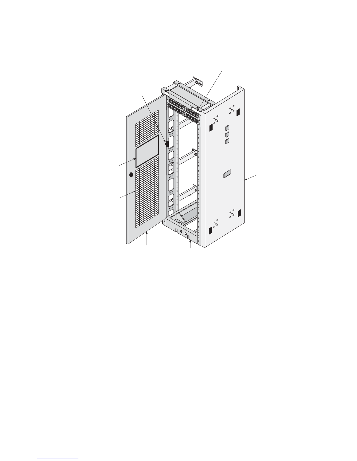
Pre-Installation Site Requirements
Figure 2-4.Door Grounding Strap Placement
EMI shield
(where required)
Perforated door
(where required)
Door
ground strap
Frame number
(label)
Frame information
(label)
End panel
(where required)
04_frame_door-gnd_generic
Door
(rear view)
Frame
(front view)
Power Requirements in a DC Environment
A Direct Current environment must supply four 40Amp feeds from the
customer’s power source. Each frame containing Tekelec products requires that
power be provided from two to four breakers at –48VDC.
Each frame is divided into A and B power buses. In the event of loss of power on
one of the buses, the other bus must be able to supply current for the entire frame.
Therefore, each bus requires wiring sized to handle up to the maximum amps at
–48VDC, with a maximum voltage drop of 0.6 volts. This requirement is met
automatically when power is supplied by breakers.
NOTE: If breakers are tripped by an overload, they must be switched
completely OFF and then ON to reset.
The following table contains detailed information on T1000 AS power
requirements in a DC environment: DC_PowerReqmts.pdf
,
2-10 910-0095-001 Revision J November 2007
Page 31

Pre-Installation Site Requirements
Power Requirements in an AC Environment
An Alternating Current environment must supply two 20 Amp feeds from
separate circuits.
910-0095-001 Revision J November 2007 2-11
Page 32

Pre-Installation Site Requirements
2-12 910-0095-001 Revision J November 2007
Page 33

T1000 AS Hardware System
Overview
T1000 AS Hardware System in a DC Environment.....................................3-3
T1000 AS Hardware Features .........................................................................3-5
3
T1000 AS Rear I/O Panel..........................................................................3-8
T1000 AS Status Indicators .......................................................................3-8
T1000 AS Chassis Installation and Replacement...................................3-9
Breaker Panels.................................................................................................3-11
Breaker Panel LEDs .................................................................................3-12
Breaker Panel Power................................................................................3-13
Breaker Panel Settings.............................................................................3-13
Ethernet Switches, Routers, or Hubs ...........................................................3-13
910-0095-001 Revision J November 2007 3-1
Page 34

Introduction
Introduction
Depending on the applications that run on them, T1000 AS hardware systems are
delivered in one of the following ways:
• Integrated applications
Most applications that run on T1000 AS systems are designed to be
integrated with features that run on a Signal Transfer Point (STP). T1000
AS systems for these applications run in a Direct Current (DC)
environment and are delivered in one of the following ways:
— For all applications, the initial installation of the T1000 AS hardware
system consists of one or more T1000 AS units, along with breaker
panels and Ethernet communication equipment, already installed by
Tekelec manufacturing in a heavy duty frame.
— Some applications allow a single T1000 AS unit to be added to a heavy
duty frame that has been previously installed and already contains
one to four T1000 AS units. To view the maximum configuration
allowed, refer to the DC assembly drawing
.
For more information about these T1000 AS hardware systems, see “T1000
AS Hardware System in a DC Environment” on page 3-3.
• Non-integrated applications
Applications (such as provisioning applications or network management
applications) that do not need to integrate with STP features may not
require a DC environment. If an application is designed to run in an
Alternating Current (AC) environment, a single T1000 AS unit is delivered
along with equipment that converts AC power to DC power.
For more information, see “T1000 AS Hardware System in an AC
Environment” on page 3-5.
To determine which environments are supported by the applications that run on
the T1000 AS systems, refer to the applications documentation.
This chapter provides an overview of T1000 AS hardware systems in each of the
possible environments and an overview of each of the components that can be
part of a T1000 AS hardware system.
3-2 910-0095-001 Revision J November 2007
Page 35

T1000 AS Hardware System in a DC Environment
T1000 AS Hardware System in a DC Environment
In a Direct Current (DC) environment, a T1000 AS hardware system consists of
the following hardware components, which are assembled in a heavy-duty frame
by Tekelec and delivered as one unit when first ordered (some applications allow
additional T1000 AS units, to a maximum of five, to be added later):
• Depending on the applications loaded, from one to five T1000 AS units,
identified as A through E, starting with the topmost server identified as A.
Each server consists of T1000 AS hardware that is loaded at the factory
with platform software and application software. Some applications allow
each server to be installed with different application software. (The
minimum and maximum number of servers in the frame depends on
which applications are loaded; for more information, refer to the
applications documentation and to the DC assembly drawing
overview of the T1000 AS units, see “T1000 AS Hardware Features” on
page 3-5.
NOTE: Some applications allow individual T1000 AS units (to a
maximum of five per frame) to be added later.
.) For an
• Two Breaker Panels (BPs). For an overview, see “Breaker Panels” on page 3-11;
for more information, refer to the documentation delivered with the product.
• Additional equipment, such as consoles and communications switches,
routers, and hubs. For more information on these components, refer to the
documentation delivered with the product.
Figure 3-1 shows an example T1000 AS hardware system in a DC environment.
NOTE: This figure shows the maximum configuration of five servers in the
frame. For more complete information about the configuration used by the
application, refer to the DC assembly drawing
.
910-0095-001 Revision J November 2007 3-3
Page 36

T1000 AS Hardware System in a DC Environment
Figure 3-1. T1000 AS Hardware System in DC Environment
2 Breaker
panels
Drip pan
Site specific
system hardware
A
TekServer Unit Frame
DC Envioronment
TekServer units
(maximum
configuration
shown)
B
C
D
E
03_ts_frame_flat-front
3-4 910-0095-001 Revision J November 2007
Page 37

T1000 AS Hardware System in an AC Environment
T1000 AS Hardware System in an AC Environment
In an Alternating Current (AC) environment, a T1000 AS hardware system
consists of the following hardware components, which are delivered as separate
units and are assembled at the customer site in a frame supplied by the customer
(the frame can be either 19 inches or 23 inches wide):
• One T1000 AS unit, which is loaded at the factory with platform software and
application software. For an overview of the T1000 AS units, see “T1000 AS
Hardware Features” on page 3-5.
• A rectifier, which accepts an AC voltage and produces a regulated DC
voltage output. For an overview, see “Rectifier” on page 3-14; for more
information, refer to the documentation delivered with the product.
Figure 3-2 shows an example T1000 AS hardware system in an AC environment.
Figure 3-2. T1000 AS Hardware System in AC Environment
Rectifier
TekServer
T1000 AS Hardware Features
The Tekelec 1000 Services Platform is a general-purpose application engine (AE)
that offers high transaction rates with low latency. It supports a variety of
application solutions for the wireless and wireline telecommunications
infrastructure to provide the building blocks for next-generation signaling
systems.
Unit
03_ts_ac_frame
The Tekelec 1000 Services Platform is a scalable computing platform constructed
with state-of-the-art components packaged in a compact-size, stand-alone
enclosure. The Tekelec 1000 chassis utilizes dual processors, and has eight PCI
slots, four internally mounted media devices, and expandable memory.
910-0095-001 Revision J November 2007 3-5
Page 38

T1000 AS Hardware Features
Figure 3-3 shows a single Tekelec 1000 Services Platform. For clarity, it is shown
not mounted in a frame.
Figure 3-3. Tekelec 1000 Chassis
CRITICAL
MAJOR
MINOR
EJECT
EJECT
POWER A
POWER B
Tekserver
03_ts_front_iso
Figure 3-4 shows an exploded view of the T1000 AS chassis. This view shows
where the various hardware components, especially the Field Replaceable Units
(FRUs), are located.
3-6 910-0095-001 Revision J November 2007
Page 39

Figure 3-4. Exploded View of T1000 AS Chassis
4
T1000 AS Hardware Features
3
5
6
2
03_ts_expld_frus
6 = the entire
TekServer unit
1
Field Replaceable Units (FRUs)
The following correspond to the Field Replaceable Units shown in Figure 3-4:
1. Air filter
2. Fan assemblies
3. Hard disk assembly (only the assembly on the left side is shown as an
exploded view)
4. Removable media disk drive assembly
5. Peripheral Component Interconnect (PCI) cards
6. Entire T1000 AS chassis
For more information about FRUs, see Chapter 7, “Field Replaceable Units.”
For more information about the hardware components, see Appendix A, “T1000
AS Hardware Feature Information.”
910-0095-001 Revision J November 2007 3-7
Page 40

T1000 AS Hardware Features
T1000 AS Rear I/O Panel
The rear input/output (I/O) panel is perforated to facilitate airflow and forms the
back wall of the Tekelec 1000 enclosure. It has openings for:
• Eight peripheral component interface (PCI) cards' I/O panels
• The I/O connectors on the rear edge of the main board (mouse, keyboard,
VGA, serial port, E1 or T1 clock inputs, and two USB ports)
• The power board I/O (logic ground connection)
Power entry is at the rear of the Tekelec 1000 platform. There are two right angle
power connectors (A and B feeds) on the power board that are accessible through
the rear I/O panel. The power input connectors are keyed and have positive
locking features.
Logic ground is carried on a 15-position, right-angle connector on the power
board. The connector is bulkhead-mounted to the rear I/O panel. There are also
two chassis ground connector studs on the rear I/O panel. See Figure 3-5 for a
detailed view of the rear I/O panel.
NOTE: Figure 3-5 shows empty PCI slots.
Figure 3-5. Rear I/O Panel
Rear Cable arm
connection
Chassis ground
(2) USB
T1000 AS Status Indicators
The T1000 AS platform provides the following light-emitting diode (LED) status
indicators on the front panel of the Tekelec 1000 platform (see Figure 3-6):
• Critical, Major, and Minor visual alarm indicators indicate operational
condition of the Tekelec 1000 platform, including status of the major
subsystems: processors, volatile memory, non-volatile memory (disk drives,
etc.), and interfaces.
USB
RJ45 B
-48 VDC Input B
Logic ground -48 VDC Input A
PWR A
A
B
LOGIC GND
CLK
VGA
VGA Serial
RJ45 A
SERIAL
RS-232
PWR B
Mouse
Keyboard
PCI8 PCI7 PCI6 PCI5 PCI4 PCI3 PCI2 PCI1
PCI slots
PCI 1
slot
03_ts_flat-rear
• Indicators for A and B power inputs.
3-8 910-0095-001 Revision J November 2007
Page 41

Figure 3-6. T1000 AS Status Indicators
Alarm Indicators
Status Indicators
Power Indicators
T1000 AS Hardware Features
03_ts_front_status
For more information about the diagnostics that manage these alarm and status
indicators, see “T1000 AS Diagnostics” on page A-6.
T1000 AS Chassis Installation and Replacement
The T1000 AS chassis is installed in the frame using slides that have inner and
outer rails. The outer slide rail is attached to the frame and the inner slide rail is
attached to the T1000 AS chassis (see Figure 5-1 on page 5-3). The chassis is
installed by sliding the inner rails into the outer rails.
DANGER: Moving a T1000 AS chassis requires two people. Each T1000 AS
chassis weighs approximately 30 kg (65 lbs) and may cause personnel injury or
damage to the internal components due to shock and vibration if not handled
properly.
The Tekelec 1000 chassis is also field replaceable. Tekelec 1000 replacement,
including disconnecting cables, mounting a replacement system (of identical
configuration), and reconnecting cables requires no more than 30 minutes.
NOTE: All I/O connections are at the rear of the Tekelec 1000 chassis.
Table 3-1 lists the dimensions of the Tekelec 1000 chassis.
910-0095-001 Revision J November 2007 3-9
Page 42

T1000 AS Hardware Features
Table 3-1. Tekelec 1000 Chassis Dimensions
Dimension Value Notes for Rack-Mounting
Depth 20.6 inches from front
Height 6.9 inch high (4U)
Width 17.6 inches wide, with
1. Tekelec makes no warranties for servers that are installed without proper clearances or
that are removed from Tekelec-standard frames.
2. The Tekelec 1000 enclosures should be free to slide only during installation, service, or
repair; they should be locked down at all other times.
surface to rear
bulkhead
form factor
slides
Allows over 2.5 inches of depth for cable management
in a Tekelec Heavy Duty Frame. The pull handles on the
front lid protrude 0.75 inches leaving 0.3 inches of
clearance between the handles and a perforated door
assembly. Chassis slide lock brackets are used to anchor
the Tekelec 1000 chassis in position during normal
operation.
Allows for multiple Tekelec 1000 chassis and associated
Ethernet switches to be mounted in a Tekelec Heavy
Duty frame
Allows for a Tekelec 1000 chassis to be installed in 19
inch racks. Adapter plates are required to mount a
Tekelec 1000 chassis with slide rails in 23 inch frames.
Cable Management Arms
The T1000 AS is installed on slides for easy access. When the chassis is slid in or
out, strain on the cables is relieved by one of the following cable management
systems:
• Side Cable Management Arms
These cable management arms are attached to the sides of the frame and
fold inward towards the back of the T1000 AS it is slid out from the frame
(see Figure 3-7 on page 3-11). A T1000 AS chassis that is shipped with
these cable management arms also includes tension bars that are mounted
on the rear of the server to further reduce strain on the cables.
3-10 910-0095-001 Revision J November 2007
Page 43

Figure 3-7. T1000 AS with Side Cable Management Arms
Breaker Panels
• Rear Cable Management Arm
Breaker Panels
Breaker panels are used to provide redundant power paths to T1000 AS units and
other equipment in a heavy duty frame in a DC environment.
Figure 3-8 shows the two breaker panels used to provide redundant power paths:
• An upper breaker panel, called BP-1
• A lower breaker panel, called BP-2
Each breaker panel has two sides: side A and side B. Each side has seven breakers,
although only certain breakers on each side are active (closed). The open position
of each breaker is marked by “O” and “|” marks the closed position.
The Rear Cable Management Arm attaches to the rear of the T1000 AS and
unfolds as the T1000 AS is slid out.
NOTE: Rear Cable Management Arm systems are no longer being
shipped with new T1000 AS installations.
910-0095-001 Revision J November 2007 3-11
Page 44

Breaker Panels
Figure 3-8. Front of Breaker Panel
A
A
Mounting screws
Breaker Panel LEDs
Figure 3-9 shows a close-up of the power module, also called the “Indicator
Panel,” in the center of the front of each breaker panel.
Figure 3-9. Breaker Panel LEDs
A
Breaker Panel 1
Breaker positions A1-A7 Breaker positions B1-B7
1234567 1234567
Front View
BREAKER
ALARM
ALARM
RESET
INPUT
POWER
BREAKER
ON
AB AB
Mounting screwsMounting screws
Breaker Panel 2
Breaker positions A1-A7 Breaker positions B1-B7
1234567 1234567
Front View
BREAKER
ALARM
ALARM
RESET
INPUT
POWER
BREAKER
ON
AB AB
Mounting screws
Front View Detail
BREAKER
LED
Breaker positions A1-A7 Breaker positions B1-B7
1234567 1234567
ALARM
ALARM
RESET
INPUT
BREAKER
AB A B
LEDs
BREAKER
ALARM
INPUT
RESET
BREAKER
AB AB
Front View
POWER
ON
ALARM
POWER
ON
09_breaker_leds
B
B
09_breakers_front
B
The power module contains two pairs of light-emitting diodes (LEDs), each
labeled
A and B with respect to the side of the breaker panel that the LED
represents:
• The pair of LEDs labeled
operation. If one of the rear input breakers opens (pops out), its respective
LED is off (not illuminated).
• The pair of LEDs labeled
operation. If power is lost coming to the breaker panel, the affected LED is off
(not illuminated.)
NOTE: If one of the
BREAKER LED will also be off and the BREAKER ALARM LED will be
illuminated red.
3-12 910-0095-001 Revision J November 2007
INPUT BREAKER is on (illuminated green) for normal
POWER ON is also on (illuminated green) for normal
POWER ON LEDs is off, the respective INPUT
Page 45

Breaker Panel Power
The breakers receive power from the input circuit on their respective side. Each
breaker controls the power to its corresponding power feed on the back of the
breaker panel. The power feeds connect to the individual hardware devices in the
frame.
Power comes into each breaker panel on side A and on side B. Each input power
line connects to the input power feeds in the rear of the breaker panel. Each input
power feed has an input circuit breaker beside it that ensures that the power is
within an acceptable range.
Breaker Panel Settings
To view a table that shows the mapping of breakers to the devices, see
DC_BreakerSettings.pdf
associated breakers should be closed. Inactive breakers are not required to be in
the closed position.
Ethernet Switches, Routers, or Hubs
. When a server is installed and powered up, the
NOTE: The breaker mapping table shows only end-to-end connectivity from
the breaker panel breakers to the servers. For detailed information on wiring,
see the DC interconnect diagram
.
Ethernet Switches, Routers, or Hubs
Ethernet switches, routers, or hubs cross-connect all the components in a heavy
duty frame. To determine which type of Ethernet switch, router, or hub is used,
see the DC assembly drawing
routers, or hubs, refer to the documentation that was delivered with the product.
. For more information about the Ethernet switches,
Console Servers
Some T1000 AS hardware systems contain a console server, which provides access
to the console ports of the T1000 AS units and allows Tekelec Customer Care
Center to access remotely the T1000 AS units. A console server is used only
during maintenance and failure conditions. To determine whether a console
server is used, see the DC assembly drawing
For more information about the console server hardware, refer to the
documentation that was delivered with the product. For information about how
to configure the console server, contact Tekelec Customer Care Center (see
“Customer Assistance” on page 1-7).
.
910-0095-001 Revision J November 2007 3-13
Page 46

Rectifier
Rectifier
In Alternating Current (AC) environment, a rectifier is used to accept AC input
from the environment’s power source and produce DC output that can be used by
the T1000 AS unit.
Rectifier Overview
Figure 3-10 shows an example rectifier.
Figure 3-10. Rectifier
AC power plug
2 amp
rectifier
module
2 amp
rectifier
module
Blank
rectifier
module
Rectifier module
serial number
In a T1000 AS hardware system in an AC environment, the rectifier system
contains two rectifier modules; Figure 3-10 shows two rectifier modules, one each
in Slots 1 and 2, and a blank module in Slot 3. Each rectifier module is
hot-swappable (can be replaced without turning off power to the rectifier
system).
For a more detailed drawing of the rectifier, see AC_PowerSystem.pdf
information about its features, refer to the documentation delivered with the
product.
Rectifier Breaker Settings
Slot 1
Slot 2
Slot 3
2 breakers
03_rectifier-ac_power
Rectifier system
serial number
Door latch
. For more
To turn on power from the rectifier to the T1000 AS unit, open the door at the
right of the rectifier and turn all the breakers to ON.
3-14 910-0095-001 Revision J November 2007
Page 47

4
How to Install a T1000 AS Frame
Introduction.......................................................................................................4-2
How to Unpack the T1000 AS Frame and Conduct Inventory..................4-2
How to Install a T1000 AS Frame...................................................................4-2
Recommended Tools..................................................................................4-3
How to Prepare the Floor for Heavy Duty Frames...............................4-4
How to Anchor the HD Frame to the Floor ...........................................4-6
How to Anchor to Overhead Rack of HD Frame................................4-17
How to Cable a T1000 AS Frame..................................................................4-19
910-0095-001 Revision J November 2007 4-1
Page 48

Introduction
Introduction
This chapter describes how to unpack and install in a DC environment a
heavy-duty frame that contains from one or more T1000 AS units and associated
equipment.
For information about installing a T1000 AS unit in an AC environment and about
installing an additional T1000 AS unit into a heavy-duty frame that already
contains from one to four T1000 AS units, see Chapter 5, “How to Install
Hardware in an Existing Frame.”
NOTE: The total number of T1000 AS units allowed in a frame depends on
the application. For more complete information about the maximum
configuration allowed by the application, refer to the DC assembly drawing
How to Unpack the T1000 AS Frame and Conduct Inventory
When the T1000 AS hardware system frame arrives, perform the following
procedure:
.
Procedure 4-1. How to Unpack Frame and Conduct Inventory
1. Unpack the heavy-duty frame, using the procedure described in 822-0094-02.
2. Ensure that all the parts listed on the packing list have been received.
3. Ensure that the part numbers on the labels on the left and right sides of each
T1000 AS unit match the sales order for each of the following categories:
• Base configuration for hard disk
• Installed memory information
• PCI card configuration
For information about the fields on a label, see “T1000 AS Chassis Part
Number Information” on page B-16.
4. Be sure to return the frame’s shipping container, as described in 822-0094-02.
5. This procedure is complete.
How to Install a T1000 AS Frame
A Heavy Duty (HD) frame is a specific Tekelec frame that has a specific footprint.
It should not be confused with other 19- or 23-inch standard frames.
4-2 910-0095-001 Revision J November 2007
Page 49

To install and anchor a heavy duty frame, perform the following tasks:
• Prepare the floor. See page 4-4.
• Anchor the frame to the floor. See page 4-6.
NOTE: The anchoring procedure and the anchor assembly to use
depend on the type of floor on which the frame is to be installed.
• Anchor the frame to the ceiling using an overhead rack. See page 4-17.
Recommended Tools
All Tekelec tools should be labeled “Property of TEKELEC” with either a press-on
Field Tool Identification label (P/N 658-0941-01) or Field Tool Identification wrap
(P/N 658-0941-02).
•Safety glasses
• Ear protectors
• Mounting hardware kit (P/N 840-0092-01)
How to Install a T1000 AS Frame
• Isolator pad (in mounting hardware kit), also used as template
• Chalk (or chalk line)
• Fiberglass tape measure
• Felt tipped marking pen
• Rotary impact drill
• 18 mm (11/16 inch) masonry drill-bit
• 1 inch (25.4 mm) masonry drill-bit
• Extension cord
• High Efficiency Particulate Air (HEPA) vacuum cleaner
• Masking tape
• File
• 3/4 inch (19mm) box-end wrench
• 3/4 inch (19mm) socket wrench
• Carbide-toothed hole saw
• Sub-floor marking tool (star bit)
•Hammer
910-0095-001 Revision J November 2007 4-3
Page 50

How to Install a T1000 AS Frame
How to Prepare the Floor for Heavy Duty Frames
Frame layout is site specific; Figure 4-1 on page 4-4 shows the most typical frame
layout. The recommended minimum aisle spacing is 3 ft. (91.5 cm) front and rear.
The following subsections provide instructions on marking the floor layout and
preparing raised floors.
How to Mark the Floor Layout
Use the following procedure to mark the floor layout.
Procedure 4-2. Mark Floor Layout
1. Verify with a customer representative that the required area dimensions and
equipment location correspond with the marked floor plan.
2. Use the floor plan provided with the engineering site file specifications to
mark the front base line and the borders of the first frame with the chalk line.
3. Align the frame template (isolator pad) with either of the two sides marked
“This side front” along the front chalk line. Using a felt tip pen, mark Anchor
locations in the middle of each oval anchor slot. Mark the corners of the first
frame as shown in Figure 4-1.
Figure 4-1. Floor Marking Template for HD Frame
25 7/8
inches
Second
template
position
Chalk line
23 5/8
inches
04_floor_mounting_template
Slots
12 inch minimum
from existing telco
equipment
Chalk lines defining front
and starting end of lineup
Rear
First
template
position
This side front
Front
6 inches spacing
4-4 910-0095-001 Revision J November 2007
Page 51

How to Install a T1000 AS Frame
4. Create another chalk line that allows 6 inches between each frame for correct
spacing.
Align the template (isolator pad) again against the front chalk line and
continue the process of aligning, marking, and moving the template (isolator
pad) until the site specific number of frame spaces has been laid out.
5. This procedure is complete.
Next, do one of the following:
• If you are installing the frame on a slab floor, see Procedure 4-4, “Anchor a HD
Frame into a Slab Floor,” on page 4-7.
• If you are installing the frame on a raised floor, see Procedure 4-3, “Create
Cable and Anchor Holes for Raised Floors,” on page 4-5.
Additional Preparations for Raised Floors
Use the procedures in this section to prepare floors for anchoring frames on raised
floors. For raised floors, you must create cable and anchor holes in the raised floor
tiles.
Procedure 4-3. Create Cable and Anchor Holes for Raised Floors
1. Mark the spots where the cable holes are to be drilled. (The spots where the
anchor holes are to be drilled were marked in Procedure 4-2, “Mark Floor
Layout,” on page 4-4.)
2. Mark the corners of the raised floor tiles to ensure the same tiles will be
returned to the same place when the procedure is complete.
3. Remove the tiles from the equipment area.
4. Use a HEPA vacuum cleaner to collect the shavings while drilling. Using a
carbide-toothed hole saw of the appropriate diameter, drill the cable holes
required in the raised floor tiles. For the anchor holes, drill 1 inch (2.54 cm)
diameter holes in the tiles corresponding to the marked anchor locations. Use
a file to remove any sharp edges from the drilled tiles.
5. Return to the equipment area with the drilled tiles and replace the tiles,
making sure the holes match where the frame anchors will be installed.
6. You have completed this procedure.
910-0095-001 Revision J November 2007 4-5
Page 52

How to Install a T1000 AS Frame
Next, perform one of the following procedures, depending on the anchoring
method you choose:
• Procedure 4-5, “Anchor the Frame to the Slab Beneath the Raised Floor,” on
page 4-11
• Procedure 4-6, “Anchor Frame to Raised Floor with Support Channel,” on
page 4-14
• Procedure 4-7, “Anchor Frame with Support Channel/Spring Nut,” on page
4-16
How to Anchor the HD Frame to the Floor
See the following sections for instructions on anchoring heavy duty frames to the
floor. These procedures are for typical installation sites with slab (concrete) floors
and raised floors. You might have to accommodate these procedures to the
unique features of your site. Depending upon your floor, use the procedure in one
of the following sections:
• Anchoring directly to a slab floor (see “How to Anchor Frame to Slab Floor”
on page 4-6)
• Anchoring to a slab floor beneath a raised floor (see “How to Anchor to
Concrete Floor Under a Raised Floor” on page 4-10)
• Anchoring to a raised floor using washer and nut (see “How to Anchor on
Raised Floor Using Support Channel” on page 4-13)
• Anchoring to a raised floor using a unistrut (see “How to Anchor on Raised
Floor Using Support Channel with Spring Nut” on page 4-16)
WARNING: Before drilling holes in any flooring, verify with facilities
personnel that the area is free of gas or water pipes, ventilation plenum, and
electrical wiring conduits.
How to Anchor Frame to Slab Floor
Use the procedure in this section to anchor the frame directly to a concrete slab
floor. If you are anchoring to a raised floor above a slab floor, see “How to Anchor
to Concrete Floor Under a Raised Floor” on page 4-10. Always get permission
from facility personnel before drilling any holes for HD frame installation.
Figure 4-2 shows the components of the Anchor Assembly used for a slab floor.
4-6 910-0095-001 Revision J November 2007
Page 53

Figure 4-2. Anchor Assembly for Slab Floors
How to Install a T1000 AS Frame
5/8 inch rod
5/8 inch nut
Small steel
washer
Large steel
washer
Metal sleeve
Nylon shoulder
washer
Fiber
washer
Nylon collar
Expansion
sleeve
Cone nut
Anchor
Assembly
Exploded View
Note: When an anchor assembly is used on a raised floor,
the anchor assembly must be disassembled and the correct
length of threaded rod of the proper diameter must be used
04_anchor
for the floor height requirement.
See Note
Threaded rod
Twist off nut
Torque nut
(red plastic
cover)
Nylon
shoulder
washer
Hold-down
plate (option)
Fiber
washer
Nylon
shoulder
washer
Anchor
Assembly
Fiber
washer
Nylon collar
Expansion
sleeve
Cone nut
Frame
Isolation pad
Floor
Metal sleeve
Procedure 4-4. Anchor a HD Frame into a Slab Floor
1. Use the HEPA vacuum cleaner to collect the dust while drilling holes. At each
anchor location marked on the concrete floor, drill a hole that is 11/16 inches
(18 mm) in diameter to a depth of 3 inches (7.7 cm). The anchor and frame will
not come together properly if the hole is drilled at an angle other than 90°.
NOTE: If any obstruction is encountered while drilling the hole, fill the
unusable hole with liquid concrete. After allowing sufficient time for the
liquid concrete to set, drill the hole at another spot within the marked area.
Clean out each hole after drilling is completed.
2. Set a fully assembled anchor into each drilled hole.
910-0095-001 Revision J November 2007 4-7
Page 54

How to Install a T1000 AS Frame
3. From each anchor remove all pieces above the metal sleeve. Retain the pieces
for use in step 7.
4. Lay the isolator pad on the floor with the holes in the isolator pad aligned
over the anchor assemblies.
5. Roll the frame (still on the dolly) into position above the isolator pad.
6. Lower the frame onto the floor with the holes in the frame aligned over the
anchor assemblies. For instructions about how to lower the frame, refer to
822-0094-02.
7. Install the three square washers, the round fiberglass washer, the large steel
washer, and the torque nut (with red plastic cover) in the order shown in
Figure 4-3. (The large steel washer, nylon shoulder washer, and round fiber
washer are found in the mounting hardware kit.)
When reassembling the anchor assembly, the bottom of the threaded rod must
be flush with the bottom of the cone nut and the torque nut must be near the
top of the threaded rod.
NOTE: When reassembling any anchor bolt assembly, lightly finger
tighten only.
4-8 910-0095-001 Revision J November 2007
Page 55

How to Install a T1000 AS Frame
Figure 4-3. Anchor Installation of HD Frame into Slab Floor
Bottom of Frame
Anchor
(4 places)
Large steel
washer
Round fiber
(insulator)
washer
Square
metal washer
Qty=3
and isolator pad
04_anchor_frame_4corners
Isolation pad
8. Tighten the top nut of the anchor assembly with a socket wrench until the
twist off nut above the plastic red cover breaks free. Leave the twist off nut on
the threaded rod to indicate that the torque on the nut beneath has been set
properly.
9. This procedure is complete.
Next, go to Procedure 4-8, “Attach Overhead Rack Support,” on page 4-18.
910-0095-001 Revision J November 2007 4-9
Page 56
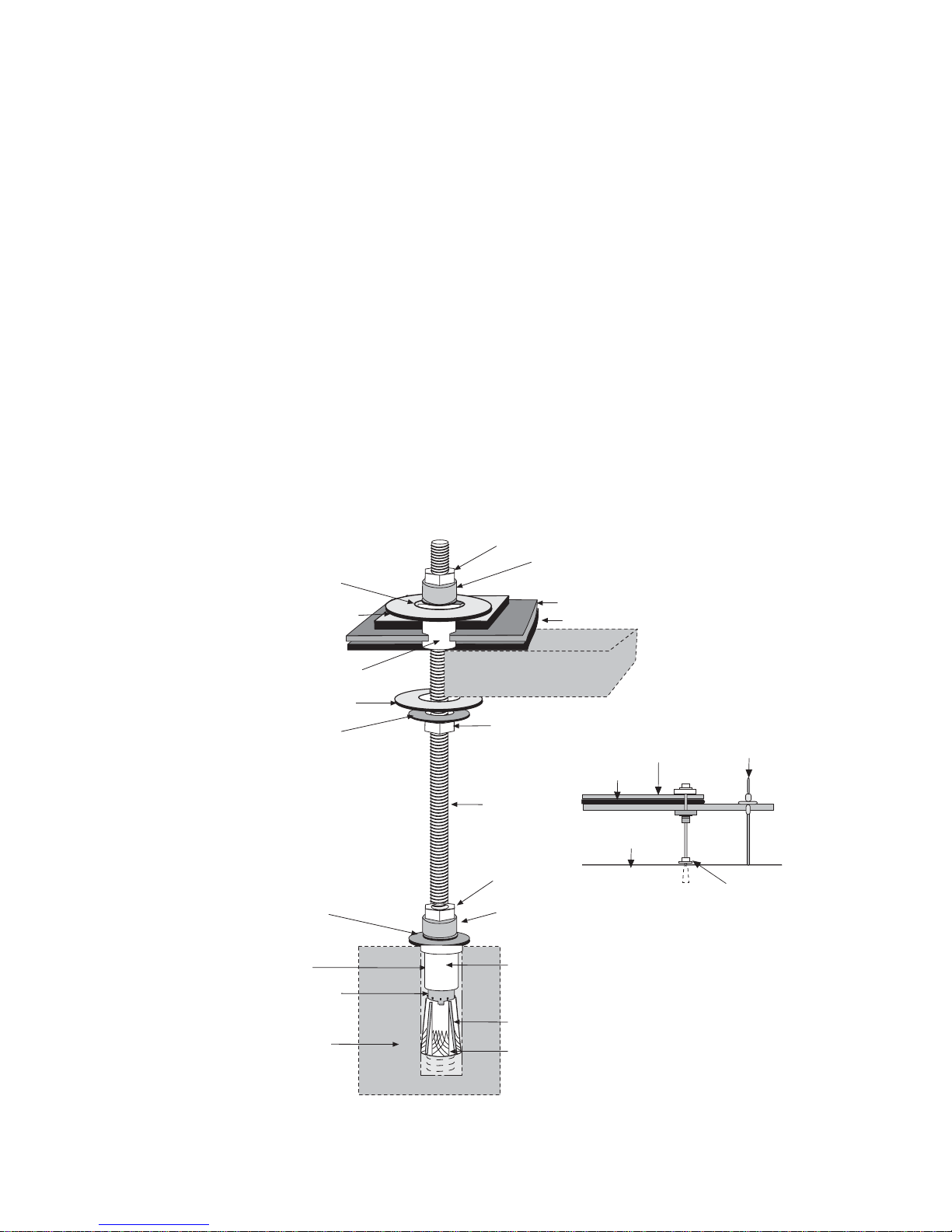
How to Install a T1000 AS Frame
How to Anchor on Raised Floors
To anchor a frame on a raised floor, use the procedure in one of the following
sections :
• “How to Anchor to Concrete Floor Under a Raised Floor” on page 4-10
• “How to Anchor on Raised Floor Using Support Channel” on page 4-13
• “How to Anchor on Raised Floor Using Support Channel with Spring Nut”
on page 4-16
How to Anchor to Concrete Floor Under a Raised Floor
Use the following procedure to anchor a frame on a raised floor to the concrete
slab beneath the raised floor. Figure 4-4 shows the components of the anchor
assembly used for a concrete floor beneath a raised floor.
Figure 4-4. Anchor Assembly for Raised Floor Over Concrete
Large fiber
washer
Hold-down plate
Nylon shoulder
washer
Large washer
Small steel
washer
Note: When an anchor assembly
is used on a raised floor, the anchor
assembly must be disassembled
and the correct length of threaded
rod of the proper diameter must be
used for the floor height
requirement.
Finger tighten nuts above
raised floor before tightening
nut directly below the raised floor
Small steel
washer
Nylon shoulder
washer
Nylon collar
Concrete floor
5/8 inch
Twist off nut
Torque nut
(red plastic
cover)
Raised floor
5/8 inch nut
Threaded rod
(see note)
Twist off nut
Torque nut
(red plastic
cover)
Metal sleeve
(inside)
Expansion
sleeve
Cone nut
Frame floor
Isolation pad
Isolation pad
Raised floor
Concrete floor
Frame floor
Sub-floor
marking
tool
Anchor assembly
with threaded rod
4-10 910-0095-001 Revision J November 2007
anchor_rsdflr
Page 57

How to Install a T1000 AS Frame
Procedure 4-5. Anchor the Frame to the Slab Beneath the Raised Floor
1. Ensure that Procedure 4-3, “Create Cable and Anchor Holes for Raised
Floors,” on page 4-5 has already been performed.
2. Perform the following substeps for each hole associated with each frame to be
installed on the raised floor:
NOTE: The threaded rod must be absolutely perpendicular to the floor.
Using a level is recommended.
a. Insert the threaded rod into the anchor holes in the tiles, making sure that
the threaded rod is perpendicular to the hole.
b. Strike the top of the threaded rod with a hammer using enough force to
mark the concrete floor.
3. Remove the floor tiles for access to the concrete floor.
4. Use a HEPA vacuum cleaner to collect the dust while drilling. Drill an 18 mm
diameter hole in the concrete floor to a depth of 3 inches (7.7 cm).
NOTE: If the hole is drilled at an angle the anchor and frame will not
come together properly.
5. Ensure that each hole is clean after the drilling is complete.
6. For each threaded rod, thread the following components in the order shown
onto one end of the rod (these components are threaded on the rod while the
rod is upside down; see Figure 4-4 on page 4-10 to identify the components
and their orientation):
a. Torque nut
b. Small steel washer
c. Metal sleeve
d. Nylon collar
e. Expansion sleeve
f. Cone nut (thread onto the rod until the end of the threaded rod is flush
with the bottom of the cone nut)
NOTE: These components should be in contact with each other, but do
not tighten the assembly because doing so could prematurely expand the
expansion sleeve.
910-0095-001 Revision J November 2007 4-11
Page 58
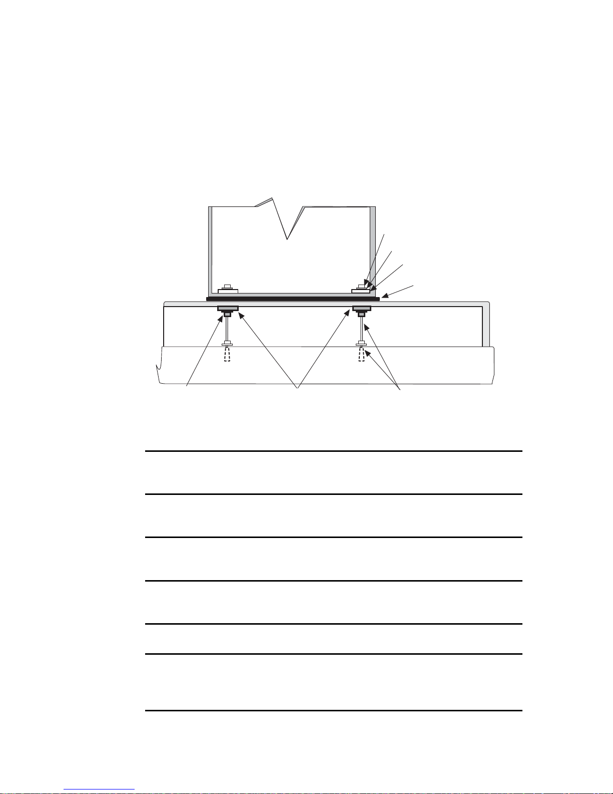
How to Install a T1000 AS Frame
7. Insert each threaded rod/anchor assembly into its hole, with the cone nut at
the bottom, and tighten with a 3/4 inch (19mm) wrench until the top nut of
the torque nut breaks free (this nut is called the twist-off nut in Figure 4-4 on
page 4-10).
Figure 4-5. Anchoring on Raised Floor Over Concrete Slab
Frame
side
Finger tighten nuts above
raised floor before tightening
nuts below raised floor
Locking nut
Washers
Holddown plate
Isolator pad
Raised floor
Concrete floor
04_raised_floor_threaded-rod
Large washer
Small washer
Nut
Flat washers
and nuts
Anchor assembly
with threaded rod
8. At the top end of each threaded rod, thread on a 5/8 inch nut until it is below
the level where the floor tile will meet the threaded rod.
9. On top of the 5/8 inch nut, drop a small steel washer and then a large steel
washer.
10. Return tiles to their original positions, fitting the anchor holes in the tiles over
the threaded rod assemblies.
11. Lay the isolator pad on the raised floor with the holes in the isolator pad
aligned over the threaded rod assemblies.
12. Roll the frame (still on the dolly) into position above the isolator pad.
13. Lower the frame onto the floor with the holes in the frame aligned over the
threaded rod assemblies. For instructions about how to lower the frame, refer
to 822-0094-02.
4-12 910-0095-001 Revision J November 2007
Page 59

How to Install a T1000 AS Frame
14. Over each threaded rod, install the following components in the order shown
(see Figure 4-4 on page 4-10):
a. Nylon shoulder washer (through the holes in the frame and isolator pad
and into the raised floor)
b. Fiber washer (around the nylon shoulder washer)
c. Square holddown plate
d. Large steel washer
e. Small steel washer
f. To r q ue nu t
15. For each threaded rod, finger-tighten the torque nut inside the frame.
WARNING: Finger-tighten nuts on threaded rods inside the frames above
the raised floor before finger tightening the nuts below the raised floor.
16. For each threaded rod, finger-tighten the 5/8 inch nut and washers against the
bottom of the floor tile (see Figure 4-5 on page 4-12).
NOTE: Tighten only until the washers and nuts are flush with the bottom
of the floor tile. DO NOT over tighten, causing the tile or frame to tilt.
17. With a 3/4 inch (19mm) socket wrench, tighten each torque nut inside the
frame until the twist off nut above the plastic red cover breaks free. Leave the
twist off nut on the threaded rod to indicate that the torque on the nut beneath
has been set properly.
18. If any tiles were removed to access the underside of the raised floor, replace
them.
19. This procedure is complete.
Next, go to Procedure 4-8, “Attach Overhead Rack Support,” on page 4-18.
How to Anchor on Raised Floor Using Support Channel
Use the following procedure to anchor the HD frame to the raised floor tiles using
the anchor assembly shown in Figure 4-6.
910-0095-001 Revision J November 2007 4-13
Page 60

How to Install a T1000 AS Frame
Figure 4-6. Anchor Assembly for Use with Support Channel
Note: When an anchor assembly is used on a raised floor, the anchor
assembly must be disassembled and the correct length of threaded rod of the
proper diameter must be used for the floor height requirement. Finger tighten
any nuts above raised floor before tightening nuts below raised floor
Anchor
Raised Floor
Small steel washer
Large steel washer
Fiber washer
Nylon shoulder
washer
Threaded rod
(see note)
Large steel washer
Small steel washer
Torque nut
(red plastic cover)
Frame floor
Isolator pad
Raised floor
Support channel
(example Unistrut)
5/8 inch nut
Frame floor
Raised floor
Concrete floor
04_raised_floor_anchor_unistrut
Support channel
(example Unistrut)
End view
Procedure 4-6. Anchor Frame to Raised Floor with Support Channel
1. Ensure that Procedure 4-3, “Create Cable and Anchor Holes for Raised
Floors,” on page 4-5 has already been performed.
2. For each threaded rod, thread the following components in the order shown
onto one end of the rod (these components are threaded on the rod while the
rod is upside down; see Figure 4-6 on page 4-14 to identify the components
and their orientation):
a. 5/8 inch nut
b. Small steel washer
c. Large steel washer
3. From underneath the raised floor, insert the threaded rod/anchor assembly
through the support channel, the raised floor, the isolator pad, and the frame
floor.
4-14 910-0095-001 Revision J November 2007
Page 61

How to Install a T1000 AS Frame
Figure 4-7. Anchoring Frame to Raised Floor with Support Channel
Tighten nut on
Small washer
Large washer
(4 PLACES)
Nut
Small washer
Large washer
Isolator pad
5 threads of the
threaded rod
must show above
the nut
Frame
side
Finger tighten nuts above
raised floor before tightening
nuts below raised floor
Support channel
(example Unistrut)
Flat washers
Lock washer
and nut
Raised floor
Concrete floor
04_raised_floor_channel-support
4. From inside the frame, drop onto each threaded rod the following
components in the order shown (see Figure 4-7):
a. Metal sleeve inside a nylon shoulder washer
b. Fiber washer (around the nylon shoulder washer)
c. Large steel washer
d. Small steel washer
e. Torque nut
Be sure to leave at least 5 threads of the threaded rod exposed inside the
frame.
5. Finger tighten the nut above the raised floor before finger tightening the nuts
below the raised floor.
6. Finger tighten the nut below the raised floor.
7. Securely tighten all the nuts above the raised floor with a socket wrench.
NOTE: Tighten only until the washer and nuts are flush with the bottom
of the floor tile. DO NOT over tighten.
910-0095-001 Revision J November 2007 4-15
Page 62

How to Install a T1000 AS Frame
8. Replace tiles if necessary.
9. This procedure is complete.
Next, go to Procedure 4-8 on page 4-18.
How to Anchor on Raised Floor Using Support Channel with Spring Nut
Use the following procedure to anchor the HD frame to the raised floor tiles using
the a support channel with spring nut.
Procedure 4-7. Anchor Frame with Support Channel/Spring Nut
1. Ensure that Procedure 4-3, “Create Cable and Anchor Holes for Raised
Floors,” on page 4-5 has already been performed.
2. Insert threaded rods through the frame and the raised floor and into the
spring nut in the support channel as shown in see Figure 4-8.
Figure 4-8. Anchor Assembly for Support Channel with Spring Nut
Anchor
Raised Floor
Note: When an anchor assembly is used on a raised floor, the anchor
assembly must be disassembled and the correct length of threaded rod of the
proper diameter must be used for the floor height requirement. Finger tighten
any nuts above raised floor before tightening nuts below raised floor
Small steel
washer
Large washer
Fiber washer
Nylon shoulder
washer
Threaded rod
(see note)
Torque nut
(red plastic cover)
Frame floor
Isolator pad
Raised floor
Spring nut
Frame floor
Raised floor
Concrete floor
04_anchor_rsdflr_no_cone
4-16 910-0095-001 Revision J November 2007
Support channel
(example Unistrut)
Page 63

How to Install a T1000 AS Frame
3. Finger tighten the rods into the spring nut in the support channels (see
Figure 4-9).
Figure 4-9. Anchoring Frame Using Support Channel/Spring Nut
Tighten nut on
Small washer
Large washer
Threaded
rod
Channel
nut
Spring
5 threads of the
threaded rod
must show above
the nut
Frame
side
Finger tighten threaded rod
through channel nut
Isolator pad
Raised floor
Concrete floor
04_raised_floor_spring-nut
Support channel
(example Unistrut)
P/N 804-0870-01
Sping washer
channel nut
P/N 804-0913-01
Unistrut
Detail
4. Insert the large washer, small washer, and torque nut onto the threaded rod on
the inside of the frame. Be sure to leave at least 5 threads of threaded rod
exposed on the inside of the frame. Tighten the nuts above the raised floor.
NOTE: DO NOT over tighten, causing the tile or frame to tilt.
5. This procedure is complete.
Next, go to Procedure 4-8, “Attach Overhead Rack Support,” on page 4-18.
How to Anchor to Overhead Rack of HD Frame
Frames with shelves that extend must be attached to overhead racks to prevent
toppling.
910-0095-001 Revision J November 2007 4-17
Page 64

How to Install a T1000 AS Frame
Procedure 4-8. Attach Overhead Rack Support
1. Using the Cable Rack Mounting kit with ladder hooks, threaded rods, and
insulators, place the assembly directly above the frame for overhead support.
2. Secure the top of the frame to the overhead racks using threaded rods with
hardware as shown in Figure 4-10 on page 4-18.
Figure 4-10. HD Frame with Overhead Rack
Nut
Auxiliary Bar
Clip
Nut
Kit P/N 804-1571-01
1-1/2
threaded rod
P/N 804-0219-01
Cable rack
3. This procedure is complete.
Mounting Kit
Cable Rack
P/N 804-1571-01
Expanded view
04_cablerack_mounting
4-18 910-0095-001 Revision J November 2007
Page 65

How to Cable a T1000 AS Frame
WARNING: Verify that all breakers are set to the OFF (O) position.
Verify that the cables already attached are connected correctly. (The T1000 AS
hardware system frame is shipped with most of the cables already attached.)
Complete any other required cable connections.
To determine the cables used and how to connect them, refer to the DC system
interconnect diagram, which lists each cable, its quantity, length, how it is used,
and a diagram of how to connect it.
NOTE: Some of the listed cables are used only as required. Actual cables used
may vary by application.
How to Cable a T1000 AS Frame
To view a drawing of a cable, refer to the DC Cable List document
the cables that appear in the system interconnect diagram with a link from each
part number to the drawing for that part number.
, which lists all
910-0095-001 Revision J November 2007 4-19
Page 66

How to Cable a T1000 AS Frame
4-20 910-0095-001 Revision J November 2007
Page 67

How to Install Hardware in an
Existing Frame
Introduction.......................................................................................................5-2
How to Unpack and Conduct Inventory ......................................................5-2
5
How to Unpack a T1000 AS Unit and Conduct Inventory ..................5-2
How to Unpack a Rectifier and Conduct Inventory.............................5-4
How to Install an Individual T1000 AS Unit ................................................5-5
How to Install the Rectifier ...........................................................................5-16
How to Cable Components Added to Existing Frames............................5-16
910-0095-001 Revision J November 2007 5-1
Page 68

Introduction
Introduction
This chapter describes how to unpack install individual T1000 AS hardware
system components and install them in frames that are already installed at
customer sites in the following situations:
For information about installing a T1000 AS hardware system that is delivered in
a frame, see Chapter 4, “How to Install a T1000 AS Frame.”
• In a Direct Current (DC) environment, some applications allow one or
more additional T1000 AS units to be ordered and delivered after the
initial T1000 AS frame has already been installed. For an overview of this
environment, see “T1000 AS Hardware System in a DC Environment” on
page 3-3.To view the maximum configuration allowed for your
application, refer to the DC assembly drawing
• In an Alternating Current (AC) environment, both the T1000 AS unit and
the rectifier are installed in a customer’s frame at the customer site. (This
chapter does not describe how to install the frame in an AC environment.)
.
How to Unpack and Conduct Inventory
To unpack and conduct inventory, see one of the following sections:
• “How to Unpack a T1000 AS Unit and Conduct Inventory” on page 5-2
• “How to Unpack a Rectifier and Conduct Inventory” on page 5-4
How to Unpack a T1000 AS Unit and Conduct Inventory
When the individual T1000 AS unit arrives, perform the following procedure:
Procedure 5-1. Unpack a T1000 AS Chassis
1. Inspect the shipping container for indication of damage. If damage is noted,
go to step 7.
DANGER: Moving a T1000 AS chassis requires two people. Each T1000
AS chassis weighs approximately 30 kg (65 lbs) and may cause personnel
injury or damage to the internal components due to shock and vibration if
not handled properly.
2. Inventory the material in the shipping container. If any discrepancies are
noted, go to step 7.
5-2 910-0095-001 Revision J November 2007
Page 69
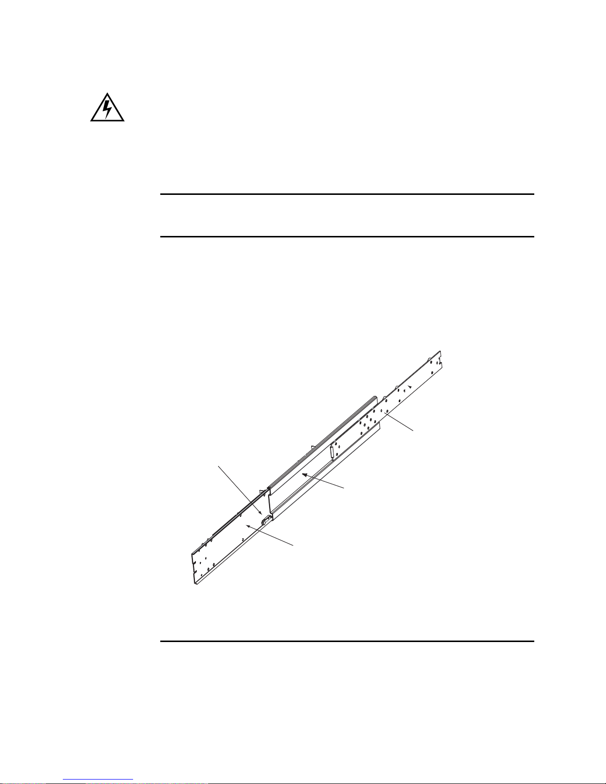
How to Unpack and Conduct Inventory
WARNING: Observe proper ESD procedures when handling the T1000
AS chassis. Always wear an ESD wrist strap connected to a grounded bench
or frame.
3. Unpack the T1000 AS chassis from the shipping container and place the unit
on a secure workbench that is grounded for ESD protection. Discard the
container and packing material.
4. Inspect the T1000 AS chassis for indication of damage. If damage is noted, go
to step 7.
5. Remove the slide assemblies from the shipping container. The slide assemblies
(see Figure 5-1) consist of three sections that will be attached to the T1000 AS
chassis and frame.
Figure 5-1. Slide Assembly
Front
Detent Latch
03_ts_slide_assy
Rear
Inner Slide Member
Release Button
Located on other side
Middle Slide Member
Outer Slide Member
910-0095-001 Revision J November 2007 5-3
Page 70

How to Unpack and Conduct Inventory
6. Inspect the slide assemblies for indication of damage. If damage is noted, go
to step 7.
7. If any damage is noted or parts are missing, contact Tekelec Customer Care
Center (see “Customer Assistance” on page 1-7).
How to Unpack a Rectifier and Conduct Inventory
When a rectifier is received, perform the following procedure:
Procedure 5-2. How to Unpack the Rectifier
1. Inspect the shipping container for indication of damage. If damage is noted,
go to step 6.
DANGER: Moving this equipment requires two people. Improper
handling of this equipment may cause personnel injury or damage to the
equipment’s internal components due to shock and vibration.
2. Inventory the material in the shipping container. If any discrepancies are
noted, go to step 6.
WARNING: Observe proper ESD procedures when handling the T1000
AS chassis. Always wear an ESD wrist strap connected to a grounded bench
or frame.
3. Unpack the rectifier from the shipping container and place the unit on a
secure workbench that is grounded for ESD protection.
4. Remove the documentation from the container and store it where you can
access it for information about the rectifier. Discard the container and packing
material.
5. Inspect the rectifier for indication of damage. If damage is noted, go to step 6.
6. If any damage is noted or parts are missing, contact Tekelec Customer Care
Center (see “Customer Assistance” on page 1-7).
5-4 910-0095-001 Revision J November 2007
Page 71

How to Install an Individual T1000 AS Unit
How to Install an Individual T1000 AS Unit
Use the following procedure to install an individual T1000 AS unit into an
existing frame. (For more information about the situations in which an individual
T1000 AS unit can be installed, see “Introduction” on page 5-2.)
Tools Required:
• #3 Phillips screwdriver
• 3/8 inch nutdriver
• Volt Ohm Meter (VOM)
Procedure 5-3. Installing a T1000 AS Chassis
TOPPLE: Before beginning this procedure, ensure the frame is properly
secured to the floor and cable racks to prevent the frame from tipping over
when the slide assembly and T1000 AS chassis is extended.
topple
DANGER: Moving a T1000 AS chassis requires two people. Each T1000 AS
chassis weighs approximately 30 kg (65 lbs) and may cause personnel injury or
damage to the internal components due to shock and vibration if not handled
properly.
1. Turn OFF the breakers that supply power to the position the T1000 AS chassis
is being installed in. Consult the system interconnect or wiring tables for the
frame or system type the T1000 AS chassis is installed in.
WARNING: A T1000 AS chassis is redundantly powered from both A and
B -48 VDC buses. Ensure that both the circuit breaker supplying A power to
a chassis and the circuit breaker supplying B power to a T1000 AS chassis
are turned OFF by measuring the voltage with a VOM on the cable that
connects the T1000 AS chassis to its breakers. Both A and B power LEDs on
the front panel of the T1000 AS chassis should be OFF.
2. Remove the front door and any plastic panels from the rear of the frame where
the T1000 AS chassis is to be installed. Using an erasable marker indicate the
location of the mounting screw holes on the frame rails reserved for the frame
brackets. T1000 AS chassis are mounted to slide assemblies attached to the
frame brackets for ease of installation and servicing.
910-0095-001 Revision J November 2007 5-5
Page 72

How to Install an Individual T1000 AS Unit
NOTE: Each T1000 AS chassis is 4 U (7 inches) in height and can be
mounted immediately above or below existing components (zero
clearance). Limits to positioning the T1000 AS in a frame are data cable
lengths, lengths of power cables to the breakers, and location of
interconnected components.
3. Locate the slide assemblies, which consist of three sections that will be
attached to the T1000 AS chassis and frame (see Figure 5-2).
4. Separate the inner slide members (with attached rollers) from the other
sections by pulling the inner and outer members apart. When a slide assembly
is approximately halfway extended, a large circular release button, located on
the side of the inner slide member, will pop into a hole in the middle slide
member. Press the release button and continue pulling the slide members
apart until the inner slide member is completely separated. See Figure 5-2 and
Figure 5-3 for details.
NOTE: Only the inner slide member will separate completely; the middle
and outer slide members are permanently connected.
Figure 5-2. Slide Assembly Extended View
Detent Latch
Middle Slide Member
Outer Slide Member
03_ts_slide_assy
Rear
Inner Slide Member
Release Button
Located on other side
5-6 910-0095-001 Revision J November 2007
Page 73

How to Install an Individual T1000 AS Unit
Figure 5-3. Slide Assembly Inner Member Roller Side View
Rear
03_ts_inner_slide_member
Slide Release Button
Front
5. Set the slide members aside for use later in this procedure.
6. Attach the four frame adapter brackets to the frame (23-inch frame only) using
two each of the #12-24 Phillips screws. Orientation is important; see Figure 5-4
and Figure 5-5 for views of the frame adapter brackets with correct
positioning. The small jog in the brackets is directed toward the rear of the
frame.
NOTE: If the frame is 19-inch, do not use the frame adapter brackets. In
19-inch frames, the slide assembly brackets that are attached to the outside
members are attached directly to the frame.
910-0095-001 Revision J November 2007 5-7
Page 74

How to Install an Individual T1000 AS Unit
Figure 5-4. Frame Adapter Bracket Expanded
Slide Assembly
Side
Figure 5-5. Frame Adapter Brackets and Slide Assemblies
Jog Toward
Rear of Frame
03_ts_frame_adapter_bracket
Frame Mounting
Side
03_ts_slides_n_brackets
Front View
Front and Rear
Frame Adapter
Brackets
Slide Assembly
Brackets
Insert Screws Here
#12-24 Phillps
Screws
5-8 910-0095-001 Revision J November 2007
Page 75

How to Install an Individual T1000 AS Unit
7. Loosely attach the rear slide assembly brackets with four #10-32 locknuts to
the outer slide members. This makes it easier when attaching the brackets to
the frame adapters or frames. See Figure 5-6. The front slide assembly brackets
are mounted at the factory.
Figure 5-6. Slide Assembly Outer Member
Inner Slide
Front Slide Assembly
Bracket
Middle Slide
#10-32 Locknuts
Rear Slide Assembly
Bracket
03_ts_outer_member_brackets
8. Attach the front and back slide assembly brackets on each slide assembly with
four #12-24 Phillips screws to the four frame adapters installed in step 6. Both
slide assemblies are identical. Viewed from the rear of the frame, orient the
slide assemblies with the rear detent latches at the bottom on the left slide
assembly and at the top on the right slide assembly. See Figure 5-7 on page
5-10 for positioning.
NOTE: The inner slide members are shown inserted into the middle slide
member in this view for clarity only. In the following steps the inner slide
members will be attached to the T1000 AS chassis and inserted into the
middle slide members.
910-0095-001 Revision J November 2007 5-9
Page 76

How to Install an Individual T1000 AS Unit
Figure 5-7. Slide Assembly Detail Left Side From Rear
Detent Latch
Front of Frame
Inner Slide Member
Middle Slide Member
Outer Slide Member
03_ts_slide_assy_left
Rear of Frame
9. Tighten the four #10-32 locknuts on each of the rear slide assembly brackets.
10. Pull the middle slide members from the outer slide members until the rear
detents latch. This allows access to the release buttons when inserting the
chassis with attached inner slide members.
11. At the workbench, attach the inner slide members that were separated in
step 4 on page 5-6, to both sides of the T1000 AS chassis with four #10-32
Phillips screws each. Orient the inner slide members with the roller bearings
outward and the center tabs toward the front of the chassis. See Figure 5-8 for
a view of the inner member on the left side of the T1000 AS chassis. The inner
slide member orientation on the right side of the chassis is similar.
5-10 910-0095-001 Revision J November 2007
Page 77

How to Install an Individual T1000 AS Unit
Figure 5-8. Slide Assembly Inner Member Mounting
Chassis
Rear
Roller Bearings
Release
Button
Four #10-32
Phillips Screws
Inner Slide Member
03_ts_inner_member_mounting
Front
Chassis Retention
Bracket
Center Tab
12. Lift the T1000 AS chassis with the attached inner slide members and carefully
insert the inner slide member rollers into the middle slide members that were
previously mounted on the frame.
13. Simultaneously press the release buttons on the inner slide members once
when the buttons encounter the middle slide members.
NOTE: The inner slide members will travel approximately two more
inches and the release buttons will detent into the round cutouts of the
middle slide members. This is the standard open position of the slides.
910-0095-001 Revision J November 2007 5-11
Page 78

How to Install an Individual T1000 AS Unit
14. Attach the Cable Management System. Do one of the following:
• For Side Cable Management Systems, attach the cable management arms
to the rear of the frame using the bolts included with the system. Be sure
that the arms can slide in toward the T1000 AS.
Figure 5-9. Detail of a Side Cable Management Arm
5-12 910-0095-001 Revision J November 2007
Page 79

How to Install an Individual T1000 AS Unit
n
Figure 5-10. Side Cable Management Arm Installation
s_cable_mgt_arm
03_t
Attach Left Side
Cable Management
Arm Here
Attach Right Side
Cable Manageme
Arm Here
• For Rear Cable Management Systems, attach the cable management arm
to the chassis and slide assembly using the captive knurled fasteners. See
Figure 5-11 on page 5-14.
910-0095-001 Revision J November 2007 5-13
Page 80

How to Install an Individual T1000 AS Unit
Figure 5-11. Rear Cable Management Arm Installation
Rear Cable
s_cable_mgt_arm
03_t
NOTE: The mounting position for the additional server may vary. The
position shown in Figure 5-11 is for example only.
15. Route and connect the power and data cables through the cable management
arm to the T1000 AS chassis. Check the labels on the cables and attach them to
the appropriate connectors on the rear of the T1000 AS chassis (see
Figure 5-12). For information about cables used, see “How to Cable
Components Added to Existing Frames” on page 5-16.
5-14 910-0095-001 Revision J November 2007
Page 81

Figure 5-12. T1000 AS Rear Detail
How to Install an Individual T1000 AS Unit
Rear Cable arm
connection
Chassis ground
(2) USB
USB
RJ45 B
A
B
CLK
RJ45 A
-48 VDC Input B
Logic ground -48 VDC Input A
PWR A
SERIAL
RS-232
PWR B
PCI 8 PCI 7 PCI 6 PCI 5 PCI 4 PCI 3 PCI2 PCI 1
Mouse
Keyboard
LOGIC GND
VGA
VGA Serial
PCI slots
PCI 1
slot
03_ts_flat-rear
16. From the front of the frame, press the round release buttons and slowly push
the T1000 AS into the frame while observing the cables to avoid binding or
stretching (see Figure 5-13).
Figure 5-13. Frame Mounting Detail
Rear frame
adapter bracket
Front slide
assembly bracket
Front frame
adapter bracket
Release button hole
Front
Retention
Middle slide member
Slide bearings
bracket screws
Inner slide member
Chassis retention
03_ts_front_bracketdetail
bracket
The chassis retention brackets on the front of the T1000 AS will contact the
frame adapters when the chassis is positioned correctly in the frame.
17. Secure the chassis with one #10-32 screw on each side in the chassis retention
brackets.
910-0095-001 Revision J November 2007 5-15
Page 82

How to Install the Rectifier
18. When the breakers that supply power to the T1000 AS chassis are switched
ON, the unit will execute a power up sequence which includes a power-on
self test (POST). For information about initializing T1000 AS applications,
refer to the applications manual.
19. Replace any plastic panels and doors that were removed.
20. This procedure is complete.
Next, perform the procedures described in Chapter 6, “Post Installation
Procedures.”
How to Install the Rectifier
For information about how to install the rectifier, refer to the documentation that
was delivered with the rectifier.
How to Cable Components Added to Existing Frames
To cable equipment added to an existing frame, follow the directions in one of the
following sections:
• “How to Cable a T1000 AS Unit Added to an Existing Heavy Duty Frame”
on page 5-16
• “How to Cable a T1000 AS and Rectifier Installed in Customer-Provided
Frame” on page 5-17
How to Cable a T1000 AS Unit Added to an Existing Heavy
Duty Frame
WARNING: Verify that all breakers are set to the OFF (O) position.
In a Direct Current (DC) environment, after an additional T1000 AS unit has been
installed, attach cables.
To determine the cables used and how to connect them, refer to the DC system
interconnect diagram, which lists each cable, its quantity, length, how it is used,
and a diagram of how to connect it.
NOTE: Some of the listed cables are used only as required. Actual cables
used may vary by application.
To view a drawing of a cable, refer to the DC Cable List document
the cables that appear in the system interconnect diagram with a link from each
part number to the drawing for that part number.
5-16 910-0095-001 Revision J November 2007
, which lists all
Page 83

How to Cable Components Added to Existing Frames
How to Cable a T1000 AS and Rectifier Installed in
Customer-Provided Frame
WARNING: Verify that all breakers are set to the OFF (O) position.
In an Alternating Current (AC) environment, after the T1000 AS unit and the
rectifier have been installed, attach cables.
To determine the cables used and how to connect them, refer to the AC system
interconnect diagram, which lists each cable, its quantity, length, how it is used,
and a diagram of how to connect it.
NOTE: Some of the listed cables are used only as required. Actual cables used
may vary by application.
To view a drawing of a cable, click on the AC Cable List document
, which lists all
the cables that appear in the system interconnect diagram with a link from each
part number to the drawing for that part number.
910-0095-001 Revision J November 2007 5-17
Page 84

How to Cable Components Added to Existing Frames
5-18 910-0095-001 Revision J November 2007
Page 85

Post Installation Procedures
Introduction.......................................................................................................6-2
How to Connect Frame Ground and Logic Ground ...................................6-2
Recommended Tools..................................................................................6-3
6
How to Ground in a DC Environment....................................................6-3
How to Ground in an AC Environment ...............................................6-11
Post-Installation Checklist.............................................................................6-13
How to Power Up...........................................................................................6-14
How to Power Up a Heavy Duty Frame ..............................................6-14
How to Power Up Added T1000 AS Unit in DC Environment.........6-14
How to Power Up a T1000 AS Unit in an AC Environment..............6-14
How to Change Passwords ...........................................................................6-15
910-0095-001 Revision J November 2007 6-1
Page 86

Introduction
Introduction
This chapter describes the activities that should be performed after either of the
following types of installation:
• A heavy duty frame that contains T1000 AS hardware has been installed
• T1000 AS hardware has been installed in an existing frame
How to Connect Frame Ground and Logic Ground
The procedures in this section must be performed before turning on the power to
the frame. To ground a T1000 AS hardware system, the following tasks must be
performed:
• Prepare the ground cables (required only in a DC environment); see “How
to Prepare the Cables” on page 6-3
• Ground the frame (required only in a DC environment); see “How to
Ground the Frame in a DC Environment” on page 6-4.
• Ground the chassis; see either of the following:
— “How to Connect T1000 AS Chassis Ground from T1000 AS Chassis to
Frame in DC Environment” on page 6-7
— “How to Connect Chassis Ground in an AC Environment” on
page 6-11
• Ground the logic for the T1000 AS unit; see “How to Ground the Logic
Connector in a DC Environment” on page 6-8
• Verify the grounding; see one of the following:
— “How to Verify the Ground in a DC Environment” on page 6-11
— “How to Verify the Ground in an AC Environment” on page 6-12
DANGER: Strictly observe all grounding requirements to reduce the risk of
electric shock.
6-2 910-0095-001 Revision J November 2007
Page 87

Recommended Tools
The following tools are recommended for procedures in this chapter:
•Safety glasses
• Multi-meter
• Cable cutters
• Cable stripper
• Socket wrench set with 1/4-inch or 3/8-inch drive or open end wrenches
• Heat-shrink gun (hot air blower)
• Torque wrench
• Fiber paper
• Power knife
• Flush cutters
• Crimping tool with embossing dies (test before using)
How to Connect Frame Ground and Logic Ground
• Non-oxidizing grease
• Lacing cord and nylon cable ties
How to Ground in a DC Environment
In a Direct Current (DC) environment, a T1000 AS hardware system operates as a
digital isolated ground plane in a central ground environment and requires a
single connection to the central ground window. The frame’s ground cables must
provide the sole grounding connection between the entire frame and the central
office grounding.
Perform the procedures in the following sections:
• “How to Prepare the Cables” on page 6-3
• “How to Ground the Frame in a DC Environment” on page 6-4
• For each server in the heavy duty frame, use the procedure in “How to
Connect T1000 AS Chassis Ground from T1000 AS Chassis to Frame in DC
Environment” on page 6-7
• “How to Ground the Logic Connector in a DC Environment” on page 6-8
• “How to Verify the Ground in a DC Environment” on page 6-11
How to Prepare the Cables
Use this procedure to prepare each frame and logic ground cable.
910-0095-001 Revision J November 2007 6-3
Page 88

How to Connect Frame Ground and Logic Ground
Procedure 6-1. Prepare the Ground Cables
1. Butt and strip the ends of the green ground cable (P/N 690-0108-07 for the
frame ground and P/N 690-0131-01 for the logic ground).
2. Slide a clear heat-shrink (P/N 804-0229-01 for the frame ground and
P/N 804-0228-R01 for the logic ground) on the butted end of the cable below
the stripped end. Move the heat-shrink past the stripped portion of the cable
to allow access to the uncovered wire.
3. Apply a thin layer of non-oxidizing grease to the uncovered wires.
4. Slide the cable lug (P/N 804-0977-R01 for the frame ground and
P/N 804-0817-R02 for the logic ground) over the stripped cable. Crimp the
lug on the cable, using an embossing crimper. The stripped cable must fill the
lug completely to the end of the barrel and be visible in the end window of the
lug.
5. This procedure is complete.
Next, go to “How to Ground the Frame in a DC Environment” on page 6-4
How to Ground the Frame in a DC Environment
This section describes how to ground the frame.
Procedure 6-2. Connect Ground Cable: Frame to Ground Window
1. Ensure that Procedure 6-1 on page 6-4 to prepare the frame ground cable
(P/N 690-0108-07) has already been performed.
2. Attach the continuous aisle ground conductor 1/0 to the Ground Window.
Run the conductor to the equipment (see Figure 6-1).
3. Install the branch ground conductor to the frame using screws and washers.
The continuous aisle ground conductor will be H-tapped to the branch (see
Figure 6-1). The separate #6 American Wire Gauge (AWG) cable ground that
runs to the frame will allow removal of a frame from a lineup without
interrupting the grounding of any other frames in the lineup. Torque screws
to 45 inch-pounds.
6-4 910-0095-001 Revision J November 2007
Page 89

How to Connect Frame Ground and Logic Ground
Figure 6-1. Frame Ground Cable Routes in DC Environment
Ground window
Producers
Absorbers
P
Continous
aisle ground
A
Neutral
Isolated
N
I
Clamp amp meter
test area
Branch
P/N 830-0715-03
7 foot frame gnd #6
(cable typical)
Bracket*
Htap
OFF
2000A
400A
400V
AC750V
DC1000V
A reading of 0.01 amps is acceptable
a higher reading is not acceptable
To Ground Window
* = Brackets
(cable rack horns)
Bracket*
Frame 1
Rear View
as required
1/0AWG
on brackets
AC/DC DIGITAL CLAMP METER
Breaker
panels
AC/DC
MAX
MAX RESET
A
TekServer System
Frame Ground
B
C
D
E
03_ts_frame_gnd
NOTE: This figure shows the maximum configuration of five servers in
the frame. For more complete information about the configuration used by
the application, refer to the DC assembly drawing.
4. Label all cables with “TO” and “FROM” location information.
Example: FROM T1000 AS frame ground, TO isolated main ground.
5. Ensure that a bolt through any nut must show at least two threads beyond the
nut, but no more than four threads should be showing.
6. Use the lacing cord to secure a “DO NOT DISCONNECT LEAD” tag at each
end of the cable, just beyond the lug. Apply the 145C cable tags to both ends of
the frame ground cable.
910-0095-001 Revision J November 2007 6-5
Page 90

How to Connect Frame Ground and Logic Ground
Figure 6-2. Frame Ground Cable Attachment Locations in
DC Environment
Cable must fill and
be visible
in lug window
12-24 Phillips head
screw with
captive star washer
(typical)
145C
#6AWG
Frame Ground To Ta p
To PANI Isolated
DO
NOT
DISCONNECT
LEAD
Frame Ground
CHASSIS
GND
CLK
USB
A
B
LOGIC GND
SERIAL
VGA
Frame Rear
Frame Ground
Ground strap
1
PWR A
PWR B
Logic Ground
Terminal Strip
03_ts_frame_logic-gnd
NOTE 1: Main Ground: 1/0 cable from the frame ground to the PANI “I”
(isolated) section of the ground window.
NOTE 2: Frame Ground: A cable #6 AWG from a frame is H-tapped into a
1/0 cable and terminates on the “I” section of the ground window. If no
ground window exists, the customer will designate the termination point.
NOTE 3: The size of the cable is determined by the overall length of the
cable run. Refer to the Site File Book.
7. This procedure is complete.
Next, go to Procedure 6-3, “Connect T1000 AS Chassis Ground: T1000 AS Chassis
to Frame,” on page 6-7.
6-6 910-0095-001 Revision J November 2007
Page 91

How to Connect Frame Ground and Logic Ground
How to Connect T1000 AS Chassis Ground from T1000 AS Chassis to Frame in
DC Environment
In a DC environment, use this procedure for each T1000 AS unit in the heavy duty
frame.
Procedure 6-3. Connect T1000 AS Chassis Ground: T1000 AS
Chassis to Frame
1. Remove the nuts on the T1000 AS chassis ground lugs on the back of the
server (see Figure 6-3 on page 6-7).
Figure 6-3. Chassis Ground Cable Attachment Location in
DC Environment
Frame Rear
Frame Ground
Logic Ground
Terminal Strip
1
03_ts_frame_chassisgnd
#6AWG
12-24 Phillips head
screw with
captive star washer
(typical)
Frame Ground
CHASSIS
GND
USB
CLK
A
B
LOGIC GND
SERIAL
VGA
Ground strap
PWR A
PWR B
2. Attach the ground cable (P/N 830-0977-01) to the server. The ground cable has
a different lug at each end and will terminate only one way.
3. Tighten the nuts to secure the cable to the rear of the T1000 AS.
910-0095-001 Revision J November 2007 6-7
Page 92

How to Connect Frame Ground and Logic Ground
4. Connect the other end of the cable to the side of the frame nearest the T1000
AS chassis (see Figure 6-2 on page 6-6). Be sure that the T1000 AS can slide in
and out on its rails without binding this cable.
5. This procedure is complete.
Next, go to Procedure 6-4, “Connect Logic Ground from Logic Ground Terminal
Strip to Ground Window,” on page 6-8.
How to Ground the Logic Connector in a DC Environment
This section describes how to attach the logic ground cables to the logic connector
at the back of the server.
The logic ground cables are a part of the internal power distribution. They
provide a ground connection between each server and the main ground. The logic
ground is connected from each server to the terminal strip and from the terminal
strip to the system bar or to the ground window by the consolidated power
cables, cable #6 AWG (P/N 690-0131-01), terminal lug (P/N 804-0817-R02), and
heat-shrink (P/N 804-0228-R01).
To complete the logic ground, both of the following procedures must be
performed:
• Attach the logic ground from the logic ground terminal block to the
system bar (EF00) or to the isolated ground of the Ground Window
(Procedure 6-4 on page 6-8).
• Attach the logic ground cable from the logic ground port on the T1000 AS
to the logic ground screws on the logic ground terminal block
(Procedure 6-5 on page 6-11).
Procedure 6-4. Connect Logic Ground from Logic Ground Terminal
Strip to Ground Window
1. Use Procedure 6-1 on page 6-4 to prepare the logic ground cable (P/N
690-0131-01).
NOTE: It may be necessary to drill the central office ground window bar
to accept the 3/8-inch bolts on one-inch centers.
2. Attach one of the ground cables to the logic ground terminal strip and the
other end to the system ground bar (EF00) or the isolated ground of the
ground window (see Figure 6-4 on page 6-9).
6-8 910-0095-001 Revision J November 2007
Page 93

How to Connect Frame Ground and Logic Ground
Figure 6-4. Logic Ground Cable Routes
Ground window
Producers
Absorbers
A
P
Neutral
Isolated
N
I
Clamp amp meter
test area
TekServer Frame
Logic ground
Bracket*
1/0AWG
on brackets
Breaker
panels
A
B
C
D
E
AC/DC
OFF
2000A
400A
400V
AC750V
DC1000V
A reading of 0.01 amps is acceptable
a higher reading is not acceptable
To Ground Window
Bracket*
Logic gnd
Frame 1
MAX
MAX RESET
AC/DC DIGITAL CLAMP METER
* = Brackets
(cable rack horns)
as required
Logic gnd
03_ts_system_logicgnd
NOTE: This figure shows the maximum configuration of five servers in
the frame. For more complete information about the configuration used by
the application, refer to the DC assembly drawing.
3. Apply the 145C cable tag (see Figure 6-5 on page 6-10) to both ends of the logic
ground cable. Also, apply the “Do Not Disconnect” tag to both ends of the
logic ground cable.
910-0095-001 Revision J November 2007 6-9
Page 94

How to Connect Frame Ground and Logic Ground
Figure 6-5. Frame and Logic Ground Cable Attachment Locations
Frame Rear
Frame Ground
Cable must fill and
be visible
in lug window
Frame Ground
Ground strap
1
Logic Ground
To PANI Isolated
DO
NOT
DISCONNECT
LEAD
Logic Ground
Terminal Strip
145C
#6AWG
CHASSIS
GND
USB
CLK
A
B
LOGIC GND
SERIAL
VGA
PWR B
PWR A
03_ts_frame_logicgnd
NOTE 1: DO NOT run Logic Ground or Power Cables on the cable horns
in the top middle of a frame.
NOTE 2: The number of inter-frame Logic Ground connections may vary
from the example shown in Figure 6-5. (One logic ground connection per
T1000 AS.)
4. This procedure is complete.
Next, go to Procedure 6-5, “Connect Logic Ground: T1000 AS Logic Ground Port
to Logic Ground Terminal Strip,” on page 6-11.
6-10 910-0095-001 Revision J November 2007
Page 95

How to Connect Frame Ground and Logic Ground
Procedure 6-5. Connect Logic Ground: T1000 AS Logic Ground Port
to Logic Ground Terminal Strip
1. Connect one end of the logic ground cable with the 15-pin connector to the
port labeled “Logic Ground” at the rear of the T1000 AS chassis. This cable
does not need any special preparation and can be used as delivered with the
server.
2. Connect the other end of the cable to one of the screws on the logic ground
terminal strip at the top right side of the frame. Do this for each server. See
Figure 6-5 on page 6-10.
3. This procedure is complete.
Next, go to “How to Verify the Ground in a DC Environment” on page 6-11.
How to Verify the Ground in a DC Environment
After all frame components and all frame and logic ground cables are installed,
the hardware tester must verify the frame and logic grounds. Power-up the frame
using the procedure described in “How to Power Up” on page 6-14. Then, use the
multi-meter to test the isolated continuous aisle ground at the position show in
Figure 6-1 on page 6-5. The meter reading with the frame powered-up must be
less than 0.01 Amps.
How to Ground in an AC Environment
Perform the procedures in the following sections:
• For each server in the heavy duty frame, use the procedure in “How to
Connect Chassis Ground in an AC Environment” on page 6-11
• “How to Verify the Ground in an AC Environment” on page 6-12
How to Connect Chassis Ground in an AC Environment
Use the following procedure to ground the T1000 AS chassis to the rectifier
chassis in an AC environment.
Procedure 6-6. Connect Chassis Ground: T1000 AS Chassis to
Ground on Rectifier
1. Attach the chassis cable into the back of the T1000 AS chassis. This cable can
be used as delivered with the server.
2. Connect the other end of the cable to the back of the rectifier chassis.
910-0095-001 Revision J November 2007 6-11
Page 96

How to Connect Frame Ground and Logic Ground
Figure 6-6. Ground Cable Attachment Locations for T1000 AS
in AC Environment
Rectifier System Rear View
LOGIC GND
CLK
USB
Chassis ground
A
B
VGA
SERIAL
3. This procedure is complete.
PWR B
Chassis ground
AC grounding
cable
PWR A
PCI 8 PCI 7 PCI 6 PCI 5 PCI 4 PCI 3 PCI 2 PCI 1
05_ts_ac_chassis_gnd
TekServer Rear View
How to Verify the Ground in an AC Environment
Use the following procedure to o verify ground in an AC environment.
Procedure 6-7. Verify AC ground
1. Take the black lead of a VOM and insert it into the ground post on the AC
source plug/outlet being tested.
2. Take the red lead of the VOM and insert it into one of the hot sides of the
plug/outlet. The meter should now read 208 VDC.
3. While keeping the black lead in place, remove the red lead from the branch it
was inserted into in step 2 and insert it into the other branch of the
outlet/plug. Again the meter should read 208 VDC.
4. This procedure is complete.
6-12 910-0095-001 Revision J November 2007
Page 97

Post-Installation Checklist
After you have performed installation procedures in this manual, fill out the
checklist shown in Table 6-1.
Table 6-1. Post-Installation Checklist
Check
When
Done
All items listed in the Equipment Specification have been installed.
Shipping container is properly packed with ramp and frame dollies and shipped to
Tekelec.
This check applies only after a heavy duty frame has been installed.
The site is clean.
Systems are neat, clean, and level.
All cable connections are checked to ensure a tight and complete connection.
Cabling is neatly installed and the labels are correct and easily readable.
Power cabling does not run through a cable rack.
Power cabling is not routed together with any other cables and has at least six inches
of clearance.
Post-Installation Checklist
Verify that:
Racks have protective paper between the rack and any cables that would otherwise
touch the rack.
The main ground cable is correctly labeled and is marked “TO and “FROM” with the
“Do Not Remove” tag installed on both ends of the cable at the grounding.
The -48 VDC power feeds are correctly labeled at the site power distribution panel.
There should be an A feed and a B feed for each breaker panel.
This check applies only in a DC environment.
The rectifier is plugged in to the AC power source.
This check applies only in an AC environment.
Any -48 VDC BATT and RTN cables are correctly labeled.
Earthquake bracing, if any, is properly installed.
Adequate floor clearances have been maintained.
Panels, if any, are correctly installed.
Cable sheets are properly filled out.
Documentation has been received and is properly stored.
Modems, if any, are operational.
910-0095-001 Revision J November 2007 6-13
Page 98

How to Power Up
How to Power Up
WARNING: Only a certified Tekelec test engineer should power up a system
after installation.
To power up, set the appropriate breakers to the ON position as described in one
of the following sections.
• “How to Power Up a Heavy Duty Frame” on page 6-14
• “How to Power Up Added T1000 AS Unit in DC Environment” on
page 6-14
• “How to Power Up a T1000 AS Unit in an AC Environment” on page 6-14
When the breakers that supply power to the T1000 AS unit are switched ON, the
unit will execute a power up sequence which includes a Power On Self Test
(POST). For information about initializing the software that runs on T1000 AS
chassis, refer to the application manuals included with your documentation.
How to Power Up a Heavy Duty Frame
In a Direct Current (DC) environment, to power up the equipment installed in the
heavy duty frame, turn ON (flip the switch toward the | indicator) all the
breakers that correspond to servers in the frame, as shown in
DC_BreakerSettings.pdf
How to Power Up Added T1000 AS Unit in DC Environment
WARNING: Before powering up a server that has been added to an existing
frame in a DC environment, verify that the breakers that correspond to the
position where the server has been added are set to the OFF (O) position.
To power up an added server, turn ON (flip the switch toward the | indicator) the
breakers that correspond to the position where the server was added, as shown in
DC_BreakerSettings.pdf
How to Power Up a T1000 AS Unit in an AC Environment
Use the following procedure to power up a T1000 AS unit in an AC environment.
WARNING: Before powering up, verify that the breakers that all rectifier
output breakers are set to the OFF (O) position.
.
.
6-14 910-0095-001 Revision J November 2007
Page 99

How to Change Passwords
Procedure 6-8. Power Up T1000 AS Unit in an AC Environment
1. Ensure that all AC and DC connections have been secured and checked.
2. Verify the ground at the AC outlet.
3. Plug the rectifier into the AC outlet.
4. Check that the rectifier is operating with no alarms present. The rectifier
controller should display “System OK.” If there are alarms present, refer to the
documentation that came with the rectifier for troubleshooting assistance
before proceeding.
5. Set the rectifier output breakers to “ON” to send power to the T1000 AS unit.
6. This procedure is complete.
How to Change Passwords
For security purposes, Tekelec recommends that all default passwords be changed
to your own passwords. The new passwords should be kept in a secure location.
• To change the passwords for the T1000 AS platforms, refer to the application
manual for the application loaded on each server.
• To change the passwords for the Ethernet switches, refer to the documentation
that accompanies that product.
NOTE: There should always be a person on-site who knows the new
passwords. If there is a need to contact Tekelec Customer Care Center, please
provide the passwords on request.
910-0095-001 Revision J November 2007 6-15
Page 100

How to Change Passwords
6-16 910-0095-001 Revision J November 2007
 Loading...