

Page 1

Tekelec EAGLE® 5
Integrated Signaling System
SIGTRAN User Guide
910-5346-001 Revision A
September 2008
Page 2

Copyright 2008 Tekelec
All Rights Reserved.
Printed in U.S.A.
Notice
Information in this documentation is subject to change without notice. Unauthorized use, copying, or translation of this
documentation can result in civil or criminal penalties.
Any export of Tekelec products is subject to the export controls of the United States and the other countries where Tekelec has
operations.
No part of this documentation may be reproduced, translated, or transmitted in any form or by any means, electronic or
mechanical, including photocopying or recording, for any purpose without the express written permission of an authorized
representative of Tekelec.
Other product names used herein are for identification purposes only, and may be trademarks of their respective companies.
RoHS 5/6 - As of July 1, 2006, all products that comprise new installations shipped to European Union member countries will
comply with the EU Directive 2002/95/EC "RoHS" (Restriction of Hazardous Substances). The exemption for lead-based
solder described in the Annex will be exercised. RoHS 5/6 compliant components will have unique part numbers as reflected
in the associated hardware and installation manuals.
WEEE - All products shipped to European Union member countries comply with the EU Directive 2002/96/EC, Waste
Electronic and Electrical Equipment. All components that are WEEE compliant will be appropriately marked. For more
information regarding Tekelec's WEEE program, contact your sales representative.
Trademarks
The Tekelec logo, EAGLE, G-Flex, G-Port, IP7, IP7 Edge, and IP7 Secure Gateway are registered trademarks of Tekelec.
TekServer, A-Port, and V-FLEX are trademarks of Tekelec. All other trademarks are the property of their respective owners.
Patents
This product is covered by one or more of the following U.S. and foreign patents:
U.S. Patent Numbers:
5,732,213; 5,953,404; 6,115,746; 6,167,129; 6,324,183; 6,327,350; 6,456,845; 6,606,379; 6,639,981; 6,647,113; 6,662,017;
6,735,441; 6,745,041; 6,765,990; 6,795,546; 6,819,932; 6,836,477; 6,839,423; 6,885,872; 6,901,262; 6,914,973; 6,940,866;
6,944,184; 6,954,526;6,954,794; 6,959,076; 6,965,592; 6,967,956; 6,968,048; 6,970,542; 6,987,781; 6,987,849; 6,990,089;
6,990,347; 6,993,038; 7,002,988; 7,020,707; 7,031,340; 7,035,239; 7,035,387; 7,043,000; 7,043,001; 7,043,002; 7,046,667;
7,050,456; 7,050,562; 7,054,422; 7,068,773; 7,072,678; 7,075,331; 7,079,524; 7,088,728; 7,092,505; 7,108,468; 7,110,780;
7,113,581; 7,113,781; 7,117,411; 7,123,710; 7,127,057; 7,133,420; 7,136,477; 7,139,388; 7,145,875; 7,146,181; 7,155,206;
7,155,243; 7,155,505; 7,155,512; 7,181,194; 7,190,702; 7,190,772; 7,190,959; 7,197,036; 7,206,394; 7,215,748; 7,219,264;
7,222,192; 7,227,927; 7,231,024; 7,242,695; 7,254,391; 7,260,086; 7,260,207; 7,283,969; 7,286,516; 7,286,647; 7,286,839;
7,295,579; 7,299,050; 7,301,910; 7,304,957; 7,318,091; 7,319,857; 7,327,670
Foreign Patent Numbers:
EP1062792; EP1308054; EP1247378; EP1303994; EP1252788; EP1161819; EP1177660; EP1169829; EP1135905;
EP1364520; EP1192758; EP1240772; EP1173969; CA2352246
Ordering Information
Your Tekelec Sales Representative can provide you with information about how to order additional discs.
Page 3

Table of Contents
Chapter 1. Introduction ..................................................................................................... 1-1
About this manual .......................................................................................................................
Audience ..................................................................................................................................... 1-2
Updates for this Release ............................................................................................................. 1-2
Manual organization ................................................................................................................... 1-2
Manual conventions .................................................................................................................... 1-3
Documentation Admonishments ................................................................................................ 1-3
Customer Care Center ................................................................................................................ 1-4
Emergency Response .................................................................................................................. 1-4
Related Publications ................................................................................................................... 1-5
Documentation Availability, Packaging, and Updates ............................................................... 1-5
Locate Product Documentation on the Customer Support Site .................................................. 1-6
Chapter 2. SS7-over-IP networks ..................................................................................... 2-1
SS7-over-IP networks overview ................................................................................................. 2-1
SS7 limitations ............................................................................................................................ 2-2
Role of SIGTRAN ...................................................................................................................... 2-2
SCTP (Stream Control Transmission Protocol) .................................................................. 2-3
M2PA (MTP2 User Peer-to-Peer Adaptation Layer) protocol ........................................... 2-4
M3UA (MTP Level 3 User Adaptation Layer) protocol ..................................................... 2-5
SUA (SCCP User Adaptation) protocol .............................................................................. 2-6
SS7-over-IP signaling transport .................................................................................................. 2-6
From SS7 message to IP packet .......................................................................................... 2-7
Communication inside the Wide Area Network (WAN) .................................................... 2-7
Reasons to transition to an SS7-over-IP SIGTRAN network ..................................................... 2-8
Cost effectiveness ................................................................................................................ 2-8
Increased capacity ............................................................................................................... 2-9
Integration ........................................................................................................................... 2-9
Type of network change ........................................................................................................... 2-10
Dedicated network versus converged IP networkt ............................................................ 2-10
Replacement versus expansion .......................................................................................... 2-10
Diversity ............................................................................................................................ 2-11
When to transition to an SS7-over-IP SIGTRAN network ...................................................... 2-11
1-1
Chapter 3. Tekelec solutions ............................................................................................. 3-1
Overview .................................................................................................................................... 3-1
EAGLE 5 ISS ............................................................................................................................. 3-1
IPLIMx, IPGWx and IPSG applications ............................................................................. 3-2
Tekelec Integrated Application Solutions (IAS) ........................................................................ 3-3
910-5346-001 Revision A, September 2008
i
Page 4

Table of Contents SIGTRAN User Guide
Integrated Message Feeder (IMF) .............................................................................................. 3-4
Chapter 4. Transition planning ........................................................................................ 4-1
Transition guidelines
Resolve high-level network design ..................................................................................... 4-1
Collect network information ............................................................................................... 4-2
Analyze data ........................................................................................................................ 4-4
Prepare configurations ......................................................................................................... 4-4
Implement and test .............................................................................................................. 4-4
Refine timers and parameters .............................................................................................. 4-5
.................................................................................................................. 4-1
Chapter 5. Dimensioning ................................................................................................... 5-1
About bandwidth, throughput, transaction units, and TPS ......................................................... 5-1
Transactions versus transaction units and TPS ................................................................... 5-2
Scalability ................................................................................................................................... 5-2
Link equivalency ................................................................................................................. 5-2
Hardware and software requirements .................................................................................. 5-4
System capacity ................................................................................................................... 5-5
Achieving IP Signaling Applications’ Advertised Capacity ...................................................... 5-5
Factors affecting advertised capacity .................................................................................. 5-6
Base transaction unit ........................................................................................................... 5-6
Adjusted transaction unit ..................................................................................................... 5-8
How to calculate transaction units per second (TPS) .......................................................... 5-8
Functionality of configurable SCTP buffer sizes per association ..................................... 5-10
System constraints affecting total IP Signaling capacity .................................................. 5-11
SIGTRAN engineering guidelines ............................................................................................ 5-13
Calculate the number of cards required ............................................................................. 5-15
IPGWx congestion management options ................................................................................. 5-16
Redundancy and link engineering ............................................................................................ 5-16
Unihoming versus multihoming ........................................................................................ 5-17
Choosing a redundancy method for M2PA links .............................................................. 5-18
Mated Signal Transfer Point redundancy .......................................................................... 5-18
IPGWx mateset .................................................................................................................. 5-19
Signaling Link Selection (SLS) routing ............................................................................ 5-20
LAN/WAN considerations ....................................................................................................... 5-20
Retransmission concept ............................................................................................................ 5-21
Retransmissions and destination status ............................................................................. 5-21
SCTP timers ...................................................................................................................... 5-21
Configure Congestion Window Minimum (CWMIN) parameter ..................................... 5-23
Chapter 6. Implementation ............................................................................................... 6-1
Hardware requirements ............................................................................................................... 6-1
EAGLE 5 ISS ...................................................................................................................... 6-1
Integrated Message Feeder (IMF) ....................................................................................... 6-2
Converting non-IPSG-M2PA Linksets to IPSG-M3UA Linksets .............................................. 6-2
Converting IPGWx M3UA Application Servers to IPSG-M3UA Linksets ............................... 6-3
IPGWx to IPSG-M3UA Conversion Example 1 ................................................................. 6-3
IPGWx to IPSG-M3UA Conversion Example 2 ................................................................. 6-5
IPGWx to IPSG-M3UA Conversion Example 2A .............................................................. 6-7
ii
910-5346-001 Revision A, September 2008
Page 5

SIGTRAN User Guide Table of Contents
Configuration .............................................................................................................................. 6-9
Configure the IPSG application
Configure the IPSG Application on the Same Card .......................................................... 6-10
Configure the IPLIMx application .................................................................................... 6-11
Configure the IPGWx application ..................................................................................... 6-12
Refine timers and parameters ................................................................................................... 6-15
Define RTIMES association retransmits ........................................................................... 6-15
Define RTO parameter ...................................................................................................... 6-15
Measure jitter ..................................................................................................................... 6-15
Refine RTO parameter ...................................................................................................... 6-15
System verification ................................................................................................................... 6-16
Verify network connectivity .............................................................................................. 6-16
Verify IPLIMx configuration ............................................................................................ 6-17
Verify IPGWx configuration ............................................................................................ 6-18
.......................................................................................... 6-9
Chapter 7. Troubleshooting .............................................................................................. 7-1
General troubleshooting ............................................................................................................. 7-1
Verify UIMs and UAMs ............................................................................................................. 7-2
Is the card configured correctly? ................................................................................................ 7-2
Connection does not become established ................................................................................... 7-3
Connection bounces and is unstable ........................................................................................... 7-3
AS/PC in route key does not become available or ACTIVE (IPGWx only) .............................. 7-3
IP destination is not informed of SS7 destination status changes; network management is
not working correctly (IPGWx only) .................................................................................. 7-4
Traffic not arriving at IP destination or traffic is lost ................................................................. 7-4
Are connection(s) congesting? ................................................................................................... 7-4
Traffic not load-balanced properly ............................................................................................. 7-5
Link level events ......................................................................................................................... 7-5
Association ................................................................................................................................. 7-5
Appendix A. Additional Deployment Scenarios ............................................................. A-1
IPLIM/M2PA deployment scenarios ......................................................................................... A-1
Simple M2PA A-link configuration (3,000 TPS) ............................................................... A-1
High-throughput M2PA A-link configuration (30,000 TPS) ............................................. A-2
High-throughput M2PA C-link configuration (30,000 TPS) ............................................. A-3
IPLIM/M2PA deployment scenarios ......................................................................................... A-3
Simple M2PA A-link configuration (3,000 TPS) ............................................................... A-3
High-throughput M2PA A-link configuration (30,000 TPS) ............................................. A-4
High-throughput M2PA C-link configuration (30,000 TPS) ............................................. A-5
IPGW/M3UA deployment scenarios ......................................................................................... A-5
Active/standby configurations ............................................................................................ A-5
Two-pair IPGWx ................................................................................................................ A-6
Four IPGWx pairs (two SS7IPW pairs and two IPGWI pairs) .......................................... A-7
Eight IPGWx cards, two mates, three linksets ................................................................... A-8
Four IPGWx cards, one linkset for end office .................................................................... A-9
Unsupported Scenarios ....................................................................................................... A-9
Appendix B. References .................................................................................................... B-1
Tekelec internal references ........................................................................................................ B-1
910-5346-001 Revision A, September 2008
iii
Page 6

Table of Contents SIGTRAN User Guide
External References ................................................................................................................... B-1
Glossary .................................................................................................................. Glossary-1
Index ............................................................................................................................. Index-1
iv
910-5346-001 Revision A, September 2008
Page 7

List of Figures
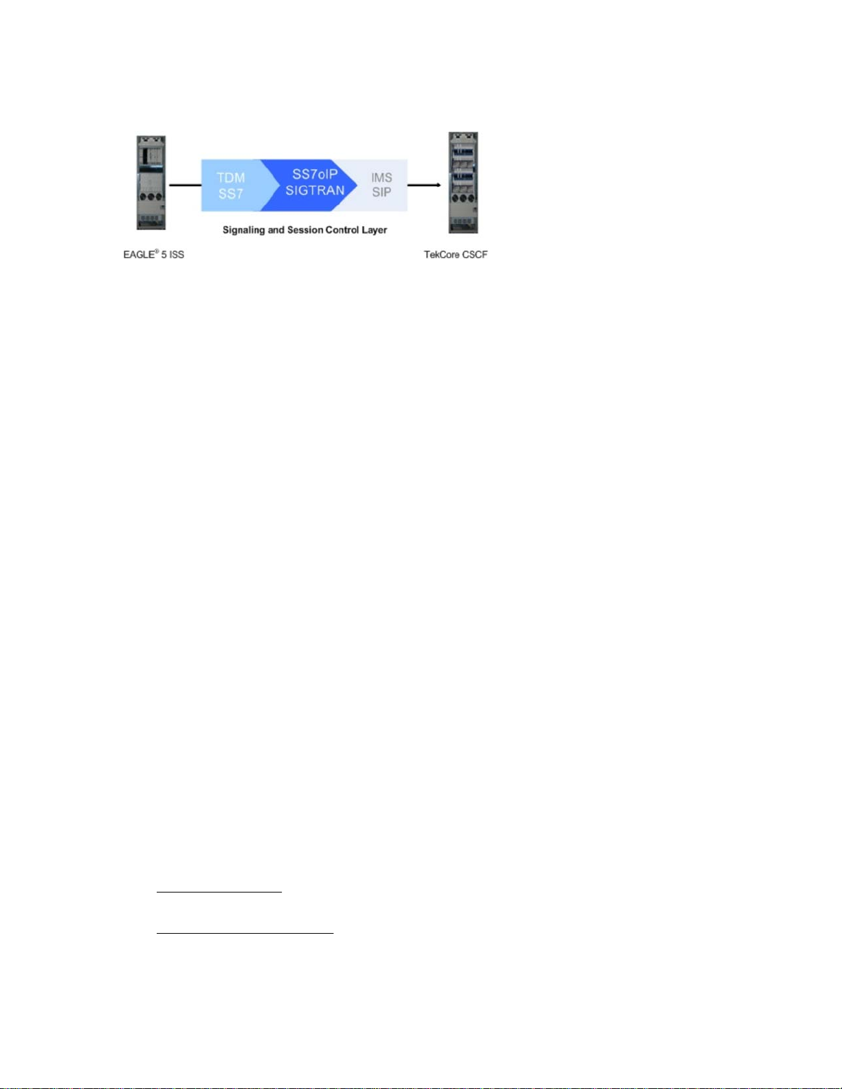
Figure 1-1. Transition from SS7 to IMS............................................................................... 1-2
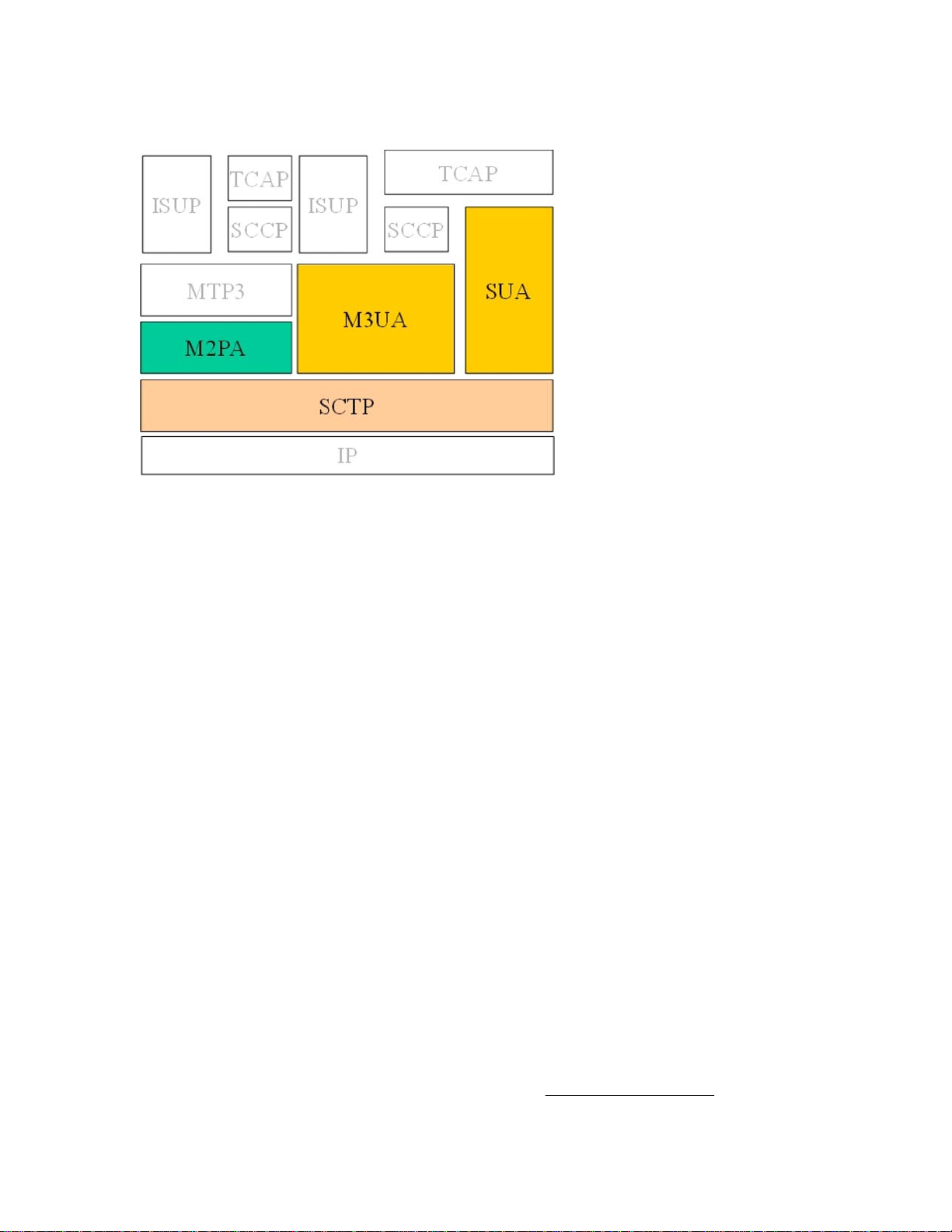
Figure 2-1. SIGTRAN protocols used by Tekelec................................................................. 2-3
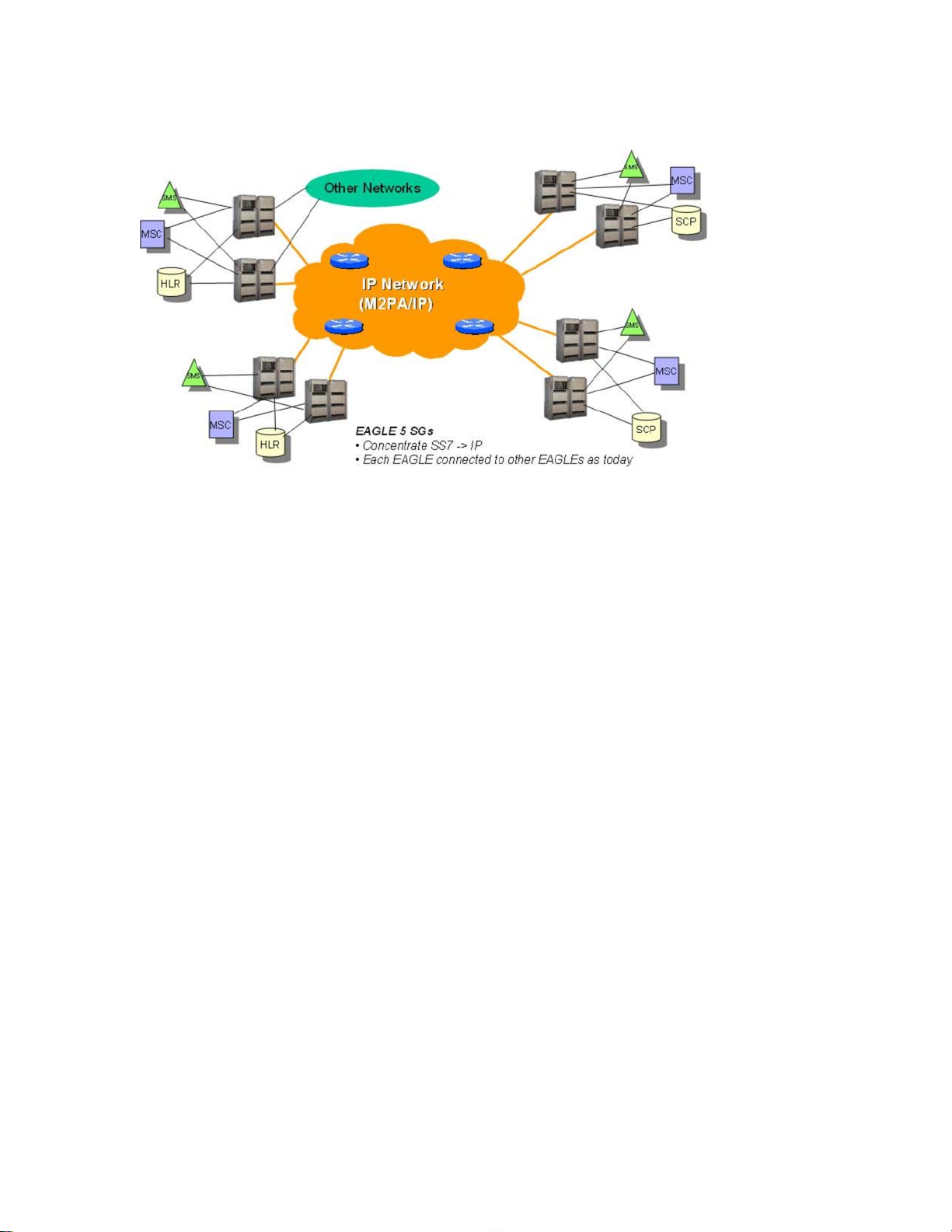
Figure 2-2. M2PA network.................................................................................................... 2-5
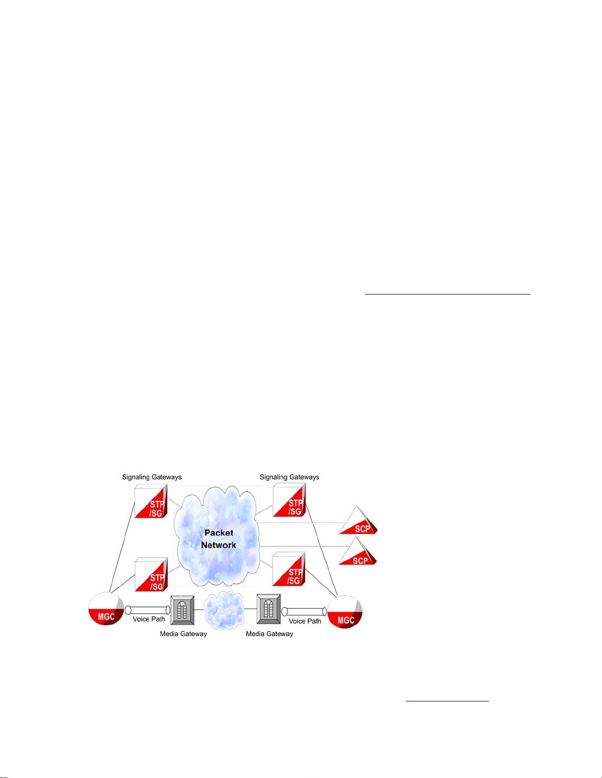
Figure 2-3. SS7-over-IP network........................................................................................... 2-6
Figure 2-4. Change from SS7 message to IP packet.............................................................. 2-7
Figure 2-5. Communication inside the WAN........................................................................ 2-8
Figure 2-6. Typical EAGLE 5 ISS SS7-over-IP deployment.............................................. 2-10
Figure 5-1. SIGTRAN: Every IP link at 0.4 erlang..............................................................
Figure 5-2. SIGTRAN: Failover at 0.8 erlang...................................................................... 5-14
Figure 5-3. SIGTRAN: Every link at 0.4 erlang and 800 MSU/s........................................ 5-14
Figure 5-4. EAGLE 5 ISS: Failover at 0.8 erlang and 1600 MSU/s.................................... 5-15
Figure 5-5. Unihoming versus multihoming........................................................................ 5-18
Figure 5-6. Mated Signal Transfer Point redundancy.......................................................... 5-19
Figure 6-1. PGWx to IPSG-M3UA Conversion Strategy Example 1.................................... 6-4
Figure 6-2. IPGWx to IPSG-M3UA Conversion Strategy Example 2................................... 6-6
Figure 6-3. IPGWx to IPSG-M3UA Conversion Strategy Example 2A .............................. 6-8
Figure A-1. SG connected to IP SEP via two M2PA links................................................... A-2
Figure A-2. SG connected to IP SEP via eleven M2PA links............................................... A-2
Figure A-3. SG connected to IP SEP via eleven M2PA links............................................... A-3
Figure A-4. SG connected to IP SEP via two M2PA links................................................... A-4
Figure A-5. SG connected to IP SEP via eleven M2PA links............................................... A-4
Figure A-6. SG connected to IP SEP via eleven M2PA links............................................... A-5
Figure A-7. IPGWx active/standby configuration................................................................. A-5
Figure A-8. Two-Pair IPGWx for Maximum TPS................................................................ A-6
Figure A-9. Four IPGWx pairs (two SS7IPW pairs and two IPGWI pairs).......................... A-7
Figure A-10. Eight IPGWx cards, two mates, three linksets................................................. A-8
Figure A-11. Four IPGWx cards, one linkset for end office................................................. A-9
Figure A-12. Unsupported deployment scenario: Combined linksets (1)........................... A-10
Figure A-13. Unsupported deployment scenario: Combined linksets (2)........................... A-10
5-14
910-5346-001 Revision A, September 2008
v
Page 8

List of Figures SIGTRAN User Guide
vi
910-5346-001 Revision A, September 2008
Page 9

List of Tables
Table 1-1. Admonishments.....................................................................................................
Table 4-1. M2PA and M3UA configuration parameter data.................................................. 4-3
Table 5-1. EAGLE Link Equivalency for IPLIMx/IPGWx................................................... 5-2
Table 5-2. EAGLE Link Equivalency for IPSG..................................................................... 5-3
Table 5-3. Card limits by application per node...................................................................... 5-5
Table 5-4. Base Advertised Capacity..................................................................................... 5-6
Table 5-5. Base transaction unit cost per MSU SIF size........................................................ 5-7
Table 5-6. Additional IPLIMx/IPGWx Transaction Units for Advanced
Configurations...................................................................................................... 5-8
Table 5-7. IPSG Additional Transaction Units for Advanced Configurations....................... 5-8
Table 5-8. Calculating TPS.................................................................................................... 5-9
Table 5-9. SCTP Buffer Space per Connection, Card and Application............................... 5-10
Table 5-10. IPLIMx and IPGWx connectivity data............................................................. 5-11
Table 5-11. IPSG Connectivity Data.................................................................................... 5-12
Table 5-12. CTP Configuration Data Descriptions for Tekelec EAGLE 5 ISS................... 5-22
Table 6-1. EAGLE 5 ISS IP signaling maximum capacities by card and application........... 6-2
1-3
910-5346-001 Revision A, September 2008
vii
Page 10

List of Tables SIGTRAN User Guide
viii
910-5346-001 Revision A, September 2008
Page 11

1
Introduction
About this manual ...............................................................................................................................................
Audience ............................................................................................................................................................. 1-2
Updates for this Release ..................................................................................................................................... 1-2
Manual organization ........................................................................................................................................... 1-2
Manual conventions ............................................................................................................................................ 1-3
Documentation Admonishments ........................................................................................................................ 1-3
Customer Care Center ........................................................................................................................................ 1-4
Emergency Response .......................................................................................................................................... 1-4
Related Publications ........................................................................................................................................... 1-5
Documentation Availability, Packaging, and Updates ....................................................................................... 1-5
Locate Product Documentation on the Customer Support Site .......................................................................... 1-6
About this manual
An SS7-over-IP network consists of a traditional SS7 network that utilizes an IP network. This document
describes SS7-over-IP networks that use the Signaling Transport (SIGTRAN) protocol suite as an enabler to
access IP networks. IP-enabled or all-IP networks are growing in popularity for both wireline and wireless operators
as they promise higher bandwidth at a lower cost, higher efficiency, and access to an exploding number of
revenue-generating services. Participation in such services becomes increasingly difficult because of the high
bandwidth required and the link restriction imposed by the traditional SS7 network.
1-1
A first step to IP success is an SS7-over-IP or SIGTRAN converged network to make reliable signaling over IP
possible without replacing the entire network. The goal is to eventually move from the converged TDM /IP network
to an all-IP network to take advantage of bandwidth, redundancy, reliability, and access to IP-based functions and
applications. Tekelec is prepared to take customers through this process at their own pace by offering expertise
and tested products that will assist in achieving this goal.
910-5346-001 Revision A, September 2008
1-1
Page 12
Audience SIGTRAN User Guide
Figure 1-1. Transition from SS7 to IMS
This document examines the reasons for transitioning to an SS7-over-IP (SSoIP) network, the considerations that
go into planning and dimensioning, and helpful information for implementing the network. This document does
not attempt to provide a beginning-to-end solution for such a transition; contact your Tekelec Sales Representative
to discuss your specific needs.
Audience
The audience
SIGTRAN-related products, as well as Tekelec customers that require an overview of SS7-over-IP networks,
SIGTRAN, and products that are part of the Tekelec solution.
for this document are Tekelec departments affected by the development, sale, or service of
Updates for this Release
The IP Signaling Gateway (IPSG) feature is introduced in release 38.0. This feature provides a signaling gateway
(SG) application as an alternative to the IPLIM and IPGW applications (the IPLIM and IPGW applications continue
to be supported). The IPSG feature can run the M2PA and M3UA protocols simultaneously on the same card, and
supports ANSI, ITU-N or ITUN-24, and ITU-I simultaneously on one card and one association. The SUA protocol
is not supported by this feature The IPSG feature runs on the E5-ENET cards only.
As part of the IPSG feature, the IPGWx Signaling TPS FAK is removed. Since customers will no longer be required
to purchase IP Signaling TPS, they can allocate as much SLKTPS as needed (up to the card limit) to accommodate
failover scenarios. The Eagle OAM enforces a system-wide IP Signaling TPS limit of 500,000 TPS provisioned
for IPGWx and IPSG link sets.
The IPSG feature works in conjunction with the SIGTRAN Measurements Phase 1 feature. The IPVSHL and the
IPVL link classes introduced in the SIGTRAN feature are used for the M2PA and the M3UA links, respectively.
See the EAGLE 5 ISS 38.0 Feature Manual for more information on these new features.
Manual organization
The manual is organized into these chapters:
Chapter 1 Introduction provides the purpose of this document, the targeted audience, how the manual is
•
organized, and Tekelec contact information.
• Chapter 2 SS7-over-IP networks describes the concept of an SS7- over-IP network and the protocols it uses,
the opportunities it provides now and what it means for future directions. This section takes the reader from
current TDM limitations, to the role of SIGTRAN, to the reasoning of why and when to transition to an
SS7-over-IP network.
1-2
910-5346-001 Revision A, September 2008
Page 13

SIGTRAN User Guide Manual conventions
• Chapter 3 Tekelec solutions describes how Tekelec products are a part of the SS7-over-IP solution. This
section describes how the EAGLE 5 Integrated Signaling System (ISS) functions as a gateway to internet
networks; and the Integrated Application Solution (IAS)
and performance tools including IP traffic monitoring through the Integrated Message Feeder (IMF) .
Chapter 4 Transition planning provides a guideline on how to prepare for a transition to an SS7-over-IP
•
network.
• Chapter 5 Dimensioning describes dimensioning issues and calculations required to maximize the efficiency
of the new network. This section addresses scalability, redundancy schemes, throughput calculations for
both normal and failover mode, LAN
Chapter 6 Implementation ” provides hardware information, high-level configuration steps for the
•
IPLIMx and IPGWx applications, how to refine timers and parameters after the installation, and highlevel system verification steps.
• Chapter 7 Troubleshooting offers troubleshooting procedures based on symptoms occurring in the network.
• Appendix A Additional Deployment Scenarios provides other possible deployment scenarios.
• Appendix B References lists Tekelec-internal and external references used in this manual. Customers
requiring access to Tekelec-internal references should contact their Sales Representative to obtain equivalent
information. This section also provides the location of customer documentation on the Tekelec Customer
Support site.
• “Glossary” defines both acronyms and terminology used in this manual.
/WAN considerations, and retransmission concepts.
, which provides several network management
Manual conventions
Several conventions are used in this document. While certain acronyms are standard in the telecom industry and
are understood by most readers, this document treats network components and feature name as proper names and
spells out their names to improve the reading of this document.
For some process descriptions, figures or tables are displayed at the beginning of the process to allow the reader
to follow most of the process on the same page. This convention is identified with each process.
Tekelec customer documentation is transitioning to sentence-style section headings to accommodate new
documentation development technologies.
Where “end points” are mentioned, the full range is included: Service Switching Points (SSPs)
Points (SCPs), Home Locator Registers (HLRs), Short Message Service Centers (SMSCs) .
, Signaling Control
Documentation Admonishments
Admonishments are icons and text throughout this manual that alert the reader to assure personal safety, to
minimize possible service interruptions, and to warn of the potential for equipment damage.
Table 1-1. Admonishments
DANGER:
910-5346-001 Revision A, September 2008
1-3
Page 14

Customer Care Center SIGTRAN User Guide
(This icon and text indicate the possibility of personal injury.)
WARNING:
(This icon and text indicate the possibility of equipment damage.)
CAUTION:
(This icon and text indicate the possibility of service interruption.)
Customer Care Center
The Tekelec Customer Care Center offers a point of contact for product and service support through highly trained
engineers or service personnel. The Tekelec Customer Care Center is available 24 hours a day, 7 days a week at
the following locations:
•
Tekelec, USA
Phone:
+1 888 367 8552 (US and Canada only)
+1 919 460 2150 (international)
Email: support@tekelec.com
• Tekelec, Europe
Phone: +44 1784 467804
Email:ecsc@tekelec.com
When a call is received, a Customer Service Report (CSR) is issued to record the request for service. Each CSR
includes an individual tracking number.
After a CSR is issued, the Customer Care Center determines the classification of the trouble. If a critical problem
exists, emergency procedures are initiated. If the problem is not critical, information regarding the serial number
of the system, COMMON Language Location Identifier (CLLI), initial problem symptoms (includes outputs and
messages) is recorded. A primary Customer Care Center engineer is also assigned to work on the CSR and provide
a solution to the problem. The CSR is closed when the problem is resolved.
Emergency Response
In the event of a critical service situation, emergency response is offered by the Tekelec Customer Care Center 24
hours a day, 7 days a week. The emergency response provides immediate coverage, automatic escalation, and other
features to ensure that the critical situation is resolved as rapidly as possible.
A critical situation is defined as a problem with an EAGLE 5 ISS that severely affects service, traffic, or
maintenance capabilities, and requires immediate corrective action. Critical problems affect service and/or system
operation resulting in:
• A total system failure that results in loss of all transaction processing capability
• Significant reduction in system capacity or traffic handling capability
1-4
910-5346-001 Revision A, September 2008
Page 15

SIGTRAN User Guide Related Publications
• Loss of the system’s ability to perform automatic system reconfiguration
•
Inability to restart a processor or the system
• Corruption of system databases that requires service affecting corrective actions
• Loss of access for maintenance or recovery operations
• Loss of the system ability to provide any required critical or major trouble notification
Any other problem severely affecting service, capacity/traffic, billing, and maintenance capabilities may be defined
as critical by prior discussion and agreement with the Tekelec Customer Care Center.
Related Publications
For information about additional publications that are related to this document, refer to the Related Publications
document. The Related Publications document is published as a part of the Release Documentation and is also
published as a separate document on the Tekelec Customer Support Site.
Documentation Availability, Packaging, and Updates
Tekelec provides documentation with each system and in accordance with contractual agreements. For General
Availability (GA) releases, Tekelec publishes a complete EAGLE 5 ISS documentation set. For Limited
Availability (LA) releases, Tekelec may publish a documentation subset tailored to specific feature content or
hardware requirements. Documentation Bulletins announce a new or updated release.
The Tekelec EAGLE 5 ISS documentation set is released on an optical disc. This format allows for easy searches
through all parts of the documentation set.
The electronic file of each manual is also available from the Tekelec Customer Support site. This site allows for
24-hour access to the most up-to-date documentation.
Printed documentation is available for GA releases on request only and with a lead time of six weeks. The printed
documentation set includes pocket guides for commands and alarms. Pocket guides may also be ordered as a set
or individually. Exceptions to printed documentation are:
• Hardware or Installation manuals are printed only without the linked attachments found in the electronic
version of the manuals.
• The Release Notice is available only on the Customer Support site.
NOTE: Customers may print a reasonable number of each manual for their own use.
Documentation is updated when significant changes are made that affect system operation. Updates resulting from
Severity 1 and 2 PRs are made to existing manuals. Other changes are included in the documentation for the next
scheduled release. Updates are made by re-issuing an electronic file to the customer support site. Customers with
printed documentation should contact their Sales Representative for an addendum. Occasionally, changes are
communicated first with a Documentation Bulletin to provide customers with an advanced notice of the issue until
officially released in the documentation. Documentation bulletins are posted on the Customer Support site and
can be viewed per product and release.
910-5346-001 Revision A, September 2008
1-5
Page 16

Locate Product Documentation on the Customer Support Site
SIGTRAN User Guide
Locate Product Documentation on the Customer Support Site
To view or download product documentation, log into the Tekelec Customer Support site at:
https://support.tekelec.com/index.asp
1. Log in with your user name and password. (Click on Need an Account? if you need to register).
2. Select EAGLE from the Product Support menu.
3. Select the release number from the Release menu.
4. Locate the Notices section to view the latest Feature Notice.
5. Locate the Manuals section to view all manuals applicable to this release.
The documentation is listed in alphabetical order by the manual name. Only the first three manuals display.
Click more… to see the remaining manuals.
6. Locate the latest revision of the manual name.
Confirm the release number and last available revision.
Select the 936-xxxx-x01 part number to download the complete documentation set with all linked files.
NOTE: The electronic file for this part number is quite large.
7. To view a manual, double-click the manual name.
8. To download a manual, right-click and select Save Target As.
NOTE: Customers may print a reasonable number of each manual for their own use.
1-6
910-5346-001 Revision A, September 2008
Page 17

2
SS7-over-IP networks
SS7-over-IP networks overview ......................................................................................................................... 2-1
SS7 limitations ....................................................................................................................................................
Role of SIGTRAN .............................................................................................................................................. 2-2
SCTP (Stream Control Transmission Protocol) .......................................................................................... 2-3
M2PA (MTP2 User Peer-to-Peer Adaptation Layer) protocol ................................................................... 2-4
M3UA (MTP Level 3 User Adaptation Layer) protocol ............................................................................. 2-5
SUA (SCCP User Adaptation) protocol ...................................................................................................... 2-6
SS7-over-IP signaling transport .......................................................................................................................... 2-6
From SS7 message to IP packet .................................................................................................................. 2-7
Communication inside the Wide Area Network (WAN) ............................................................................ 2-7
Reasons to transition to an SS7-over-IP SIGTRAN network ............................................................................. 2-8
Cost effectiveness ........................................................................................................................................ 2-8
Increased capacity ....................................................................................................................................... 2-9
Integration ................................................................................................................................................... 2-9
Type of network change ................................................................................................................................... 2-10
Dedicated network versus converged IP networkt .................................................................................... 2-10
Replacement versus expansion .................................................................................................................. 2-10
Diversity .................................................................................................................................................... 2-11
When to transition to an SS7-over-IP SIGTRAN network .............................................................................. 2-11
2-2
SS7-over-IP networks overview
An SS7-over-IP network consists of a traditional SS7 network that can integrate IP-enabled or all-IP devices with
protocols defined by the Internet Engineering Task Force (IETF) standards organization.
SS7-over-IP signaling primarily addresses the transport aspect of SS7. Call-control services and other types of
services, therefore, can continue to be offered and deployed without concern for the method of interconnection.
The method of service implementation, however, remains dependent on the particular network element chosen to
support the service rather than the transport chosen.
This section looks at the limitations of the traditional SS7 network and its network components, the role of
SIGTRAN protocols, the purpose of SS7-over-IP networks, the advantages of transitioning to this network, and
when it is time to consider transitioning.
910-5346-001 Revision A, September 2008
2-1
Page 18

SS7 limitations SIGTRAN User Guide
SS7 limitations
SS7 is a signaling network (data traffic) protocol used to send and receive signaling messages between Signaling
End Points over dedicated signaling links. Operators deploy SS7 services over a dedicated network of 56- or 64kbps Time Division Multiplexed (TDM) lines, or utilize high-speed T1 (1.5 Mbps) or E1 (2.048 Mbps) lines. SS7
uses centralized databases and services, achieves reliable connections through
because of its isolation from end users and the dedicated network. SS7 signaling is mature with standards and a
rich feature set, and offers these advantages to both wireline and wireless services.
However, SS7 limitations in scalability, bandwidth, and network availability slow network growth and
opportunities to participate in new IP services:
• Scalability is limited by 16-link linksets consisting of 64 kbps transport
Up to 16 links may be grouped into one circuit, or linkset. Adjacent network elements, such as Signal
Transfer Points (STPs) and Service Control Points (SCPs), may be connected by no more than one linkset.
The protocol further recommends that links and linksets are configured to no more than 40% of their
maximum capacity, so that the alternate path can carry the full load of messages during failover.
• Bandwidth
A traditional SS7 message size is limited to about 272 octets. E1/T1 links allow the transmission of larger
messages, but not without originating, routing, or end points supporting either large messages or message
segmentation.
network management, and is secure
A bandwidth of 56 kbps or 64 kbps per link and dedicated links reduce flexibility and increase cost
significantly when creating sufficient bandwidth for new service applications. In a TDM network, entire
transmission segments must be reserved for each call, even if the TDM connection is idle.
TDM-based SS7 is continuing to evolve, but slowly. Instead, wireline and wireless operators are looking to IP
solutions.
Role of SIGTRAN
SIGTRAN is a working group of the IETF , addressing packet -based Public Switched Telephone Network
(PSTN) signaling over IP networks. A set of signaling transport protocols has been developed out of the group’s
work. For the purposes of this document, the protocols are collectively called the “SIGTRAN” protocols or suite.
The SIGTRAN architecture used by Tekelec includes the following protocols. The figure shows their location
in the protocol stack:
• Stream Control Transmission Protocol (SCTP); RFC 4960
• MTP2 User Peer-to-Peer Adaptation Layer (M2PA) protocol; RFC 4165
• MTP3 User Adaptation Layer (M3UA) protocol; RFC 4666
• SCCP User Adaptation Layer (SUA) protocol; RFC 3868
2-2
910-5346-001 Revision A, September 2008
Page 19
SIGTRAN User Guide Role of SIGTRAN
Figure 2-1. SIGTRAN protocols used by Tekelec
SCTP (Stream Control Transmission Protocol)
SCTP is a new reliable transport protocol that operates on top of a connectionless packet network such as IP,
and operates at the same layer as TCP. It establishes a connection between two endpoints, called an association,
for transmission of user messages. To establish an association between SCTP endpoints , one endpoint provides
the other with a list of its transport addresses (one or more IP addresses in combination with an SCTP port).
These transport addresses identify the addresses that will send and receive SCTP packets. SCTP was developed
to eliminate deficiencies in TCP and offers acknowledged, error-free, non-duplicated user data transport.
IP signaling traffic is usually composed of many independent message sequences between many different signaling
endpoints. SCTP allows signaling messages to be independently ordered within multiple streams (unidirectional
logical channels established from one SCTP end point to another) to ensure in-sequence delivery between
associated end points. By transferring independent message sequences in separate SCTP streams, it is less likely
that the retransmission of a lost message will affect the timely delivery of other messages in unrelated sequences
(called head-of-line blocking). Because TCP does enforce head-of-line blocking, the SIGTRAN Working Group
recommends SCTP rather than TCP for the transmission of signaling messages over IP networks.
Security
SCTP provides certain transport-related security features, such as resistance against blind denial of service attacks,
masquerades, or improper monopolization of services.
SIGTRAN protocols do not define new security mechanisms, as the currently available security protocols provide
the necessary mechanisms for secure transmission of SS7 messages over IP networks.
Tekelec deviations
The following sections summarize the most important deviations from the IETF RFCs that Tekelec has made.
Refer to the Tekelec protocol compliance matrices for details; see
Representative for access to the information contained in these documents.
910-5346-001 Revision A, September 2008
Tekelec internal references . Contact your Sales
2-3
Page 20

Role of SIGTRAN SIGTRAN User Guide
SCTP multiple streams
There are several architectural issues regarding the use of multiple streams as described in the SCTP protocol. The
issues include:
•
Synchronization between data streams
• Synchronization from control stream to data streams
• Load-sharing implementation based on SLS across streams, either within a connection or across all the
connections in an Application Server
Since the underlying SS7 network is connectionless, a stringent requirement for missequenced messages has
been set because it is often easier to recover from the loss of a message by a time-out than from one message
delivered out-of-sequence. The Message Transfer Part (MTP) is able to maintain a high probability of
message sequencing. This is ensured by the MTP user, which generates a value for a Signaling Link Selection
(SLS) field as a parameter for each message. As the message is routed through the network, wherever there
is a choice to be made between alternate routes, the link selection is made based on the SLS value in the
message.
• Connection behavior when a stream becomes congested
A lack of consensus on the IETF SIGTRAN mailing list regarding these issues resulted in Tekelec supporting a
maximum of two streams: a control stream and a data stream.
SCTP timer
Based on experiences in the field, Tekelec has deviated from some RFC-recommended timer settings, especially
related to retransmission, to better accommodate signaling networks.
The Tekelec default mode for the retransmission timer (RMODE) is linear, whereas the RFC-recommended timer
setting is exponential. Tekelec makes both settings available through configuring an association to use either the
Linear (LIN) or the exponential (RFC) method. For more information about both modes and the timer settings,
“SCTP timers” .
see
M2PA (MTP2 User Peer-to-Peer Adaptation Layer) protocol
M2PA is used primarily to replace B-, C-, and D-links. When used with A-links, M2PA connects to Service
Switching Points , Signaling Control Points
replacement for channelized TDM circuits because it has specific controls for assurance of in-sequence delivery
of messages. As such, M2PA is needed to connect points that pass call-related data that is time-sensitive, such
as ISUP calling data.
Congestion procedures conform to those specified by the ANSI/ITU standards. The M2PA protocol can coexist
in a linkset with other link types such as low-speed links and ATM high speed links. When using other link types,
the throughput will always match the lowest-speed link in the linkset.
Tekelec implemented the M2PA protocol through its IPLIMx application. For more information on the IPLIMx
application, see
IPLIMx, IPGWx and IPSG applications .
, Home Locator Registers and other endpoints. M2PA is a direct
2-4
910-5346-001 Revision A, September 2008
Page 21
SIGTRAN User Guide Role of SIGTRAN
Figure 2-2. M2PA network
M3UA (MTP Level 3 User Adaptation Layer) protocol
M3UA seamlessly transports SS7 MTP3 user part signaling messages over IP using SCTP. M3UA-connected
IP endpoints do not have to conform to standard SS7 topology, because each M3UA association does not require
an SS7 link; there are no 16-link-per-linkset restrictions. Each M3UA-connected IP endpoint can be addressed by
an SS7 point code unique from the signaling gateway’s point code. Tekelec offers two types of topologies M3UA:
IPGWx using routing keys, and IPSG using IPSG-M3UA links.
NOTE: A-links for nodes requiring in-sequence delivery of messages should be configured on the IPLIMx
card using M2PA; M3UA does not have sequence numbers to support lossless changeover/changeback. For
more information on the IPLIMx application, see “IPLIMx and IPGWx applications” on page 20.
A routing key defines a set of IP connections as a network path for a portion of SS7 traffic, and is the IETF Signaling
Gateway equivalent of a Signal Transfer Point’s SS7 route. Routing keys are supported by the M3UA protocols
to partition SS7 traffic using combinations of Destination Point Code (DPC), Origination Point Code (OPC),
Service Indicator (SI), Network Indicator (NI), SS7 Subsystem Number (SSN), and/or Circuit Identification Code
(CIC) message fields.
Using IPGWx, M3UA-connected IP endpoints do not have to conform to standard SS7 topology, because each
M3UA association does not require an SS7 link; there are no 16-link-per-linkset restrictions. Each M3UAconnected IP endpoint can be addressed by an SS7 point code unique from the signaling gateway’s point code.
In release 38.0, M3UA can also be implemented using IPSG, supports routing keys in the form of SS7 Routes
referencing IPSG M3UA linksets, rather than as distinct ‘routing key’ managed elements. Instead, it performs
similarly to the M2PA protocol. Each M3UA association is viewed as a link by the core EAGLE, and each IPSG
card can have up to 32 associations/links per card. MTP Origin-Based Routing cannot be used with adjacent point
codes.
M3UA does not have a 272-octet Signaling Information Field (SIF) length limit as specified by some SS7 MTP3
variants. Larger information blocks can be accommodated directly by M3UA/SCTP without the need for an upper
layer segmentation or re-assembly procedure as specified by the SCCP and ISUP standards. However, a Signaling
Gateway will enforce the maximum 272-octet limit when connected to a SS7 network that does not support the
transfer of larger information blocks to the destination.
910-5346-001 Revision A, September 2008
2-5
Page 22
SS7-over-IP signaling transport SIGTRAN User Guide
At the Signaling Gateway, M3UA indicates to remote MTP3 users at IP end points when an SS7 signaling point
is reachable or unreachable, or when SS7 network congestion or restrictions occur.
NOTE: IPGW and IPSG M3UA links cannot be in the same link set at the same time. However, the EAGLE
allows IPGW and IPSG-M3UA link sets to have separate routes to the same AS, aiding in cutover.
SUA (SCCP User Adaptation) protocol
SUA transports any SS7 SCCP signaling messages over IP using SCTP, and is used between a Signaling Gateway
and a signaling end point
SUA is used to direct queries to the correct IP-based Application Server Process . It replaces the SCCP layer with
its own SUA layer and is used when source and destination are both IP.
A Signaling Gateway can determine the “next hop ” using the Global Title Translations delivered in the Called
Party Address of the Message Signaling Unit (MSU) .
NOTE: A-links for nodes requiring in-sequence delivery of messages should be configured on the
IPLIMx card using M2PA; SUA does not have sequence numbers to support lossless changeover/
changeback. For more information on the IPLIMx application, see
.
Routing keys are supported by the SUA protocol as in M3UA. Routing key parameters include DPC, OPC, SI,
and SSN.
or between signaling end points.
IPLIMx, IPGWx and IPSG applications
IPSG does not support SUA.
SS7-over-IP signaling transport
SIGTRAN protocols connect IP-based or IP-enabled Media Gateway Controllers (MGCs)
(SGs) , switches, databases and other Next Generation signaling applications with traditional circuit-switched
signaling architecture.
Figure 2-3. SS7-over-IP network.
, Signaling Gateways
In SS7-over-IP networks, traditional SS7 signals from a telephone company switch are transmitted to a Signaling
Gateway
or to a MGC , other Service Control Points, or Mobile Switching Centers (MSCs) . SIGTRAN protocols define
how the SS7 messages can be transported reliably over the IP network; see also
2-6
, which wraps the signals in an IP packet for transmission over IP to either the next Signaling Gateway
“Role of SIGTRAN” .
910-5346-001 Revision A, September 2008
Page 23
SIGTRAN User Guide SS7-over-IP signaling transport
The Signaling Gateway has a critical role in the integrated network and is often deployed in groups of two or more
to ensure high availability. The Signaling Gateway provides transparent interworking of signaling between TDM
and IP networks. The Signaling Gateway may terminate SS7 signaling or translate and relay messages over an IP
network to a Signaling End Point (SEP)
or integrated in any combination. For example, the EAGLE 5 ISS can perform the functions of a Signal Transfer
Point in addition to those of a Signaling Gateway.
or another Signaling Gateway, which may be separate physical devices
From SS7 message to IP packet
The following figure and description show how SS7 messages are encapsulated and sent over an IP network to a
host in another network.
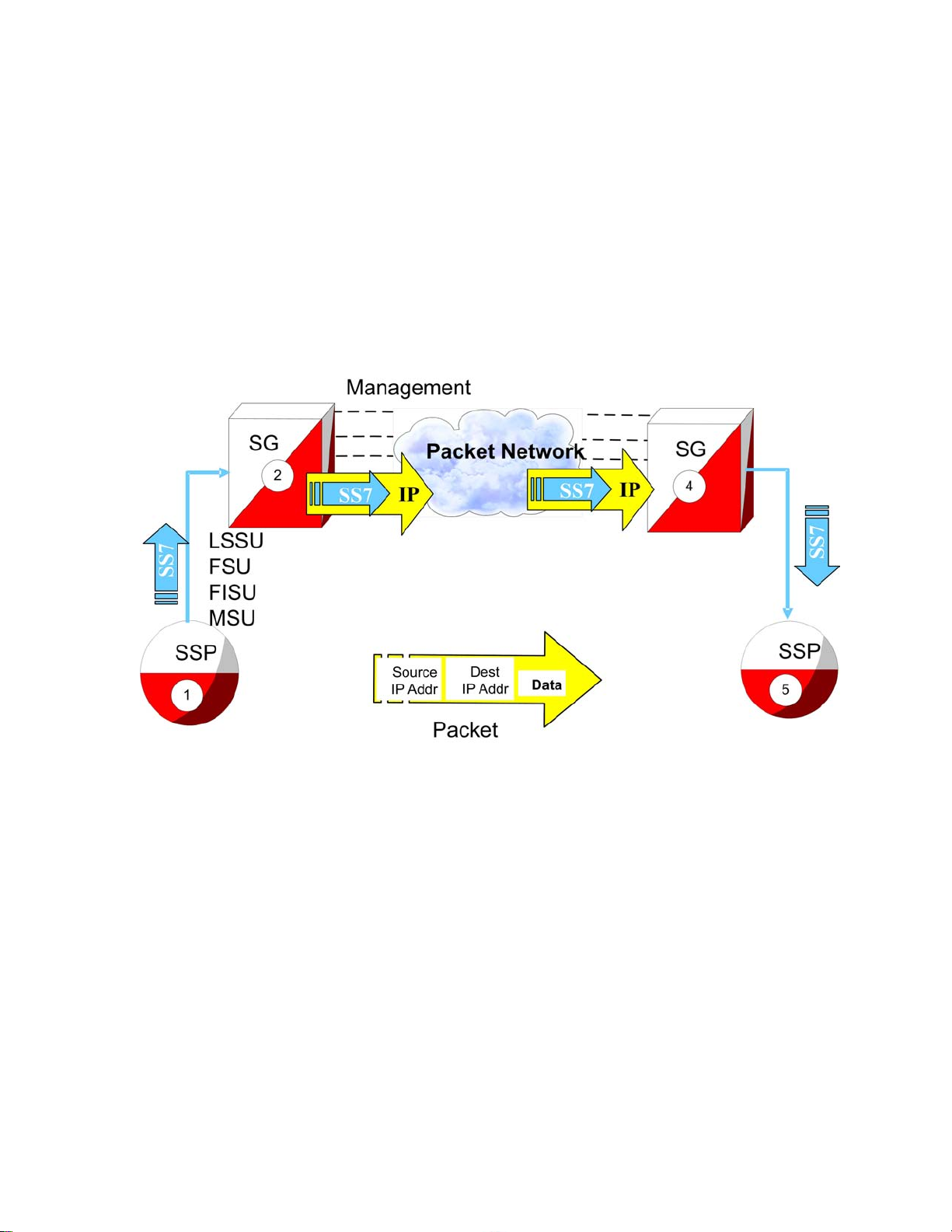
Figure 2-4. Change from SS7 message to IP packet
1. A signaling point issues an SS7 message, unaware that there is IP signaling in the network. The message
contains Link Status Signaling Units (LSSU), Fill In Signal Units (FISU), Final Signal Units (FSU), and
Message Signal Units (MSUs).
2.
The Signaling Gateway receives the SS7 packet and encapsulates all necessary SS7 information into the
data section of the IP packet. The packet includes the data, source and destination IP address.
3. The packet travels across the IP network. The network is unaware that it is delivering SS7 data. There is no
need to modify the routers or gateways along the way.
4. The packet is delivered to the Signaling Gateway on the receiving network. The SS7 information is recovered
from the IP packet.
5. A well-formed SS7 packet is sent to the destination Signaling Point.
Communication inside the Wide Area Network (WAN)
The following figure and description show the routing inside the Wide Area Network (WAN).
910-5346-001 Revision A, September 2008
2-7
Page 24
Reasons to transition to an SS7-over-IP SIGTRAN network
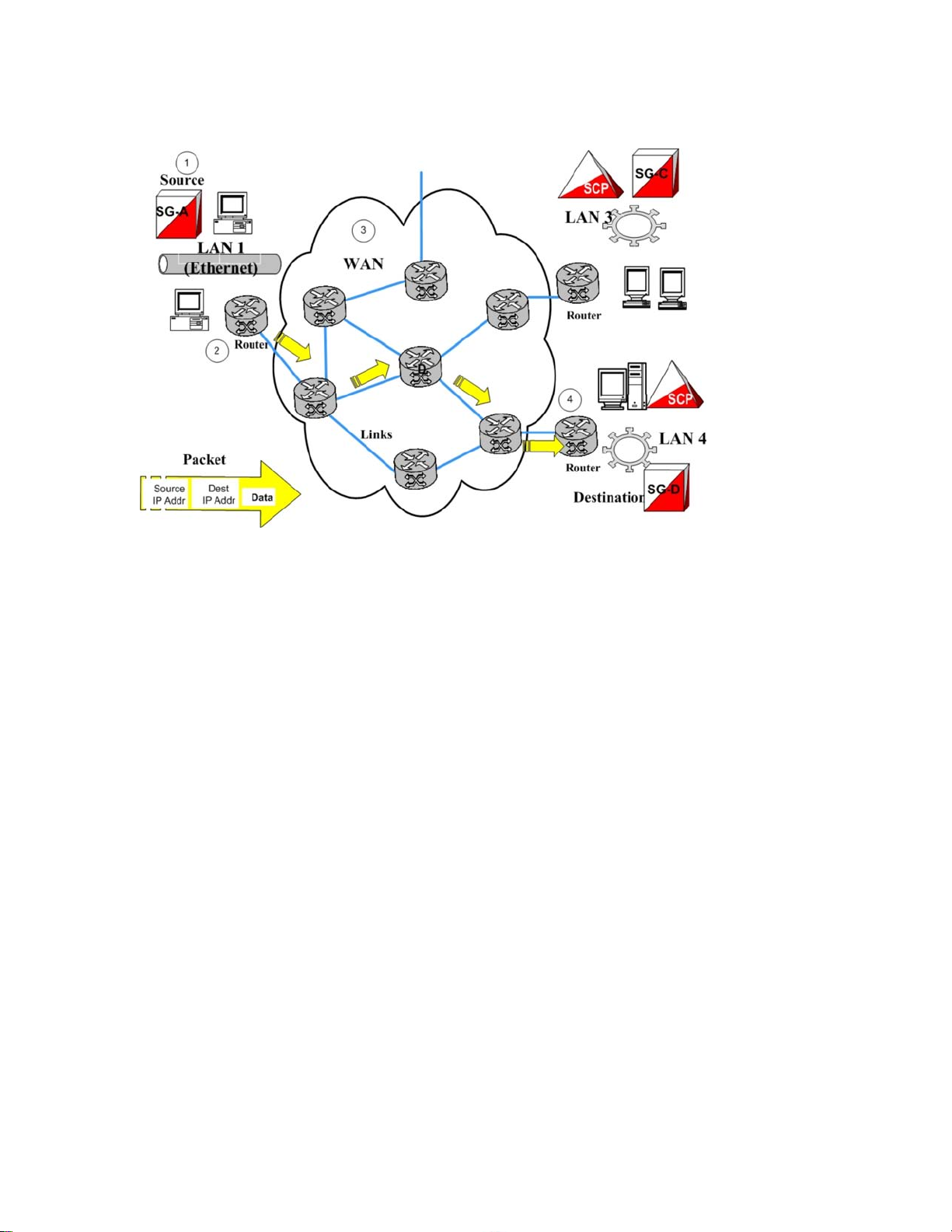
Figure 2-5. Communication inside the WAN
SIGTRAN User Guide
1. The Source Host (Signaling Gateway) builds a packet with a destination IP address.
2.
A router on the LAN converts the packet to the WAN protocol and places it on the WAN.
3. Each router on the WAN looks at the destination IP address and determines the port to which it forwards
the packet. Each router needs to know only how to get the packet closer to the destination.
4. The final router converts the packet to the local LAN format and delivers it to the Destination Host.
Reasons to transition to an SS7-over-IP SIGTRAN network
There are many reasons for transitioning to an SS7-over-IP network. The resulting network offers better cost
effectiveness, increased capacity that can be further scaled as needed, a high Quality of Service (QoS) including
redundancy and security, and efficient deployment using existing equipment.
Cost effectiveness
SS7-over-IP networks lower network capital and operational expenditures. SIGTRAN is based on the IP protocol;
these networks use industry standard, off-the-shelf network interfaces, cables, switches, and software.
Improvements in technology and reductions in cost found in the general computer industry can be applied readily
in signaling applications. As an industry standard, SIGTRAN allows customers to interoperate in a multivendor
environment.
Replacing long-haul point-to-point SS7 links between network elements with IP connectivity can reduce recurring
signaling transport costs and the need for dedicated TDM lines. IP-based network monitoring and provisioning
improve operation efficiencies.
2-8
910-5346-001 Revision A, September 2008
Page 25

SIGTRAN User Guide Reasons to transition to an SS7-over-IP SIGTRAN
network
Increased capacity
SS7-over-IP networks offer increased capacity. The bandwidt overall is greater, both due to inherent capacity
and to dynamic bandwidth sharing. Data traffic including Short Message Service (SMS) can run more efficiently
over SIGTRAN . For example, SMS data is saturating some SS7 networks. Using devices such as the Tekelec
EAGLE 5 ISS with its gateway functions, operators can have a Short Message Service Center communicate
directly to Home Location Registers (HLR) and Mobile Switching Centers (MSCs) using SIGTRAN .
Flexibility
SIGTRAN uses the packet IP network to define logical connections between devices. Because the network
developers, planners, and installers are no longer tied to deploying fixed circuits for signaling, they have the
flexibility to define the network as needs and demands change. Flexibility is key in adapting bandwidth on demand;
redimensioning the SS7-over-IP network can be done completely through software. With legacy SS7, users are
limited to either 56 or 64 kbps links.
There is also flexibility when adding capacity for new IP-based solutions and value-added services ; future
enhancements are more transparent.
Integration
Enabling a network with IP does not require expensive investments or costly upgrades for existing end nodes; it
enables migration to packet-based architecture without adding new point codes or reconfiguring the network.
For M2PA, there are no architectural changes. When using SIGTRAN, SS7 routing translations are the same for
TDM or IP linksets.
An SS7-over-IP network is the first step to an all-IP network. The following figure shows the diversity of solutions
that are possible using SIGTRAN protocols. For example, M3UA and SUA support an IP-enabled Short Message
Service Center (SMSC) or Home Location Register (HLR) . SS7-over-IP solves the throughput limitations that
were inherited from the SS7 standards, thus allowing Short Message Service Center, Home Location Register, and
other equipment to support heavy SS7 traffic needs.
910-5346-001 Revision A, September 2008
2-9
Page 26
Type of network change SIGTRAN User Guide
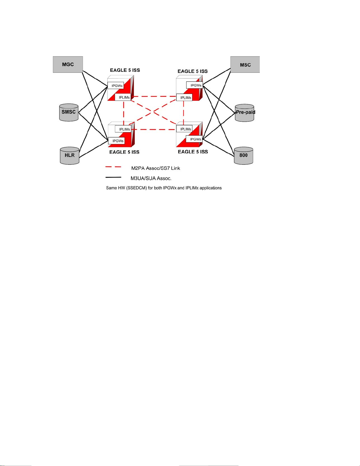
Figure 2-6. Typical EAGLE 5 ISS SS7-over-IP deployment
Type of network change
When considering a transition, determine the type of change to make. Consider the advantages and disadvantages
of a dedicated network versus a converged network. Does the equipment need to be phased out or will new
equipment be added? Does the network require additional protection or supplier integration through diversity? All
these issues should be considered in the initial planning because of their significant impact on the overall network
architecture.
Dedicated network versus converged IP networkt
While a dedicated IP network offers inherent security and minimal routing, a converged network carrying both
voice and data also will satisfy these needs at less cost, provided that the QoS attributes such as Round Trip Time
(RTT) , Packet Loss, andJitter
the IP network.
Implementing SS7-over-IP on an SS7 system creates a converged IP network that allows quick, cost-effective
implementation of IP-based services using existing network elements. The Tekelec EAGLE 5 ISS with its Signaling
Transfer Point and Signaling Gateway functions offers a reliable solution for this transition.
Decisions regarding the customization of the IP network are left up to the customer, but Tekelec Professional
Services can provide recommendations based on their experiences with previous SIGTRAN deployments.
Replacement versus expansion
When transitioning to an SS7-over-IP network, consider these strategies:
are satisfied. These attributes should always be given the highest priority on
• Replacement of out-phased (end of life) TDM equipment
• Gradual replacement, which means coexistence of the two technologies: there is no need to retire an existing
switch if you are deploying purely for additional capacity
2-10
910-5346-001 Revision A, September 2008
Page 27

SIGTRAN User Guide When to transition to an SS7-over-IP SIGTRAN
network
• Full accelerated replacement with a short transition period based on cost, efficiency, and fault management:
even if complete transition is desired, it is unrealistic to expect to instantaneously cut over unless the
subscriber base is very small.
There is enormous leverage when one platform provides both TDM and SS7-over-IP. The issue is more than
cost savings. A combined platform can support new multimodal voice, data and video services that utilize
a combination of IP data with diverse messaging capabilities, location and presence information, voice
connections, speech recognition and Intelligent Network control. Of course, not every application requires
every capability, so flexibility is key
•
Maintaining the existing PSTN network, and use Next Generation Network (NGN) equipment to satisfy
growing demands: legacy switches have many features and services.
• Operators may have to wait until new switches support all required features and services.
• Out-of-region or in-region expansion Traditional services or new features
Diversity
Supporting businesses with critical operations such as banking requires strategies for predictable recovery, not
only from regular network faults, but also from attacks on signaling networks. When planning to move to an SS7over-IP network, the operator should consider diversity to assist in recovery.
The range of diversity will differ from customer to customer and it may include a multitude of factors:
• Entry diversity offers more than one cable entrance into a building
• Pair and cable diversity provides a local loop connection through multiple, nonadjacent pairs in more than
one cable
• Path or route diversity provides end-to-end, physically or logically separate routes for a circuit
• Central office diversity provides local loops that terminate in more than one central office
• Site diversity provides alternative or backup locations
When to transition to an SS7-over-IP SIGTRAN network
Consider transitioning to an SS7-over-IP network if:
• Traffic-volume growth on the network is demanding additional capacity
• New networks are planned or IP services will be added to existing networks
• Traffic volume between signaling points is surpassing the bandwidth of 16-link linksets
• A data or voice-over-IP network is already present
• Signaling traffic is deployed over very high latency or lossier networks, such as satellite links
If signaling messages are transported over a private intranet, security measures can be applied as deemed necessary
by the network operator.
910-5346-001 Revision A, September 2008
2-11
Page 28

When to transition to an SS7-over-IP SIGTRAN
network
SIGTRAN User Guide
2-12
910-5346-001 Revision A, September 2008
Page 29

Tekelec solutions
Overview ............................................................................................................................................................ 3-1
EAGLE 5 ISS ..................................................................................................................................................... 3-1
IPLIMx, IPGWx and IPSG applications ..................................................................................................... 3-2
Tekelec Integrated Application Solutions (IAS)
Integrated Message Feeder (IMF) ...................................................................................................................... 3-4
Overview
Tekelec has set the standard for ultra-reliable, high-performance, scalable signaling in wireless and wireline
networks around the world. Advanced solutions optimize network efficiency and save customer capital and
operational costs. Tekelec addresses network transition by providing the signaling bridge to seamlessly converge
circuit and packet-switched technologies.
................................................................................................ 3-3
3
Operators can leverage existing TDM and ATM network resources as they transition at their own pace to new IPbased transport and services. Tekelec’s innovative switching solutions create cost-effective, fully scalable
networks with built-in flexibility , making it quick and easy to roll out high-margin multimedia services to business
and residential customers.
Tekelec is the IP signaling leader and the first to recognize the value of IP Signaling by developing the TALI
protocol (RFC 3094) in 1998. Tekelec was first to market with an IP Signaling solution (IPLIMx application) in
2000, and has years of IP signaling deployment experience.
There are a variety of Tekelec products available to implement a new IP network or upgrade an existing SS7
network.
EAGLE 5 ISS
The Tekelec EAGLE 5 ISS is a robust SS7-over-IP solution that delivers centralized signaling routing, and bridges
the legacy circuit-switched and packet networks. It provides seamless interworking between TDM resources such
as Service Control Points and IP-enabled elements such as Media Gateway Controllers and next-generation
databases. With its packet-based technology, the EAGLE 5 ISS can handle signaling requirements of the most
complex networks, delivering dynamic bandwidth sharing to support increases in signaling traffic without
additional nodes. The same platform delivers full Signal Transfer Point capabilities and a complete portfolio of
integrated applications.
910-5346-001 Revision A, September 2008
3-1
Page 30

EAGLE 5 ISS SIGTRAN User Guide
Using the EAGLE 5 ISS to structure the network provides a predictable and reliable architecture with all required
interfaces. It is easily scalable
expansion on different parts of the network independent of each other.
The EAGLE 5 ISS provides ease of database management for the SS7-over-IP architecture. Key benefits of using
the Tekelec SS7-over-IP solution are:
• Decreased network congestion. Tekelec’s packet-switched technology delivers dynamic bandwidth
sharing to enable carriers to effectively expand their signaling networks and reduce network bottlenecks. By
replacing TDM links with an IP interface, service providers can significantly increase signaling capacity to
Service Control Points.
• Reduced transport costs. Replacing long-haul, point-to-point SS7 links between network elements with IP
connectivity can reduce recurring signaling transport costs by 40% to 70%.
• More efficient networks. Transitioning to SS7-over-IP signaling does not require expensive equipment
replacement or costly software upgrades for existing end nodes. With Tekelec solutions, carriers can
streamline their networks while reducing administration, without service interruption during installation..
• Migration to next-generation architecture. The EAGLE 5 ISS can appear as an end office to the SS7
network by sharing its point code with the IP endpoints. This allows carriers to migrate to a packet-based
architecture without adding a new point code or reconfiguring the network. Tekelec’s open, multi-protocol
architecture (SS7, SCTP, M2PA, M3UA, and SUA) gives carriers the capability to grow and migrate their
network and the independence to choose best-in-class products.
to cover huge core networks, with an independent control layer that allows
IPLIMx, IPGWx and IPSG applications
The EAGLE 5 ISS implements SIGTRAN with three applications:
• IPLIMx , which represents IPLIM for ANSI networks and IPLIMi for ITU-N and ITU-I networks
• IPGWx , which represents IPGWx for ANSI networks and IPGWi for ITU-N and ITU-I networks
• IPSG in Release 38.0, which represents a unified application for both ANSI and ITU links on a single
association
The IPLIMx application uses SCTP with M2PA protocols to support B-, C-, and D- links; but it can also be used
for A-links to connect to SEPs on other vendor equipment that have M2PA SIGTRAN specifications implemented.
IPLIMx is fully compliant with RFC 4165.
IPLIMx is installed on either an SSEDCM card or an card. Based on the card type, IPLIMx allows up to 8 links
per SSEDCM card and up to 16 links per E5-ENET card, each with one SCTP association per link. IPLIMx can
be implemented with just one card and expanded to 100 cards per system.
The IPGWx application uses SCTP with M3UA and SUA protocols to provide user part support such as SCCP
and ISUP over A-links to IP-resident network elements such as Service Switching Points , Mobile Switching
Centers, Service Control Points and Home Location Registers using SIGTRAN. Since IPGWx applications use
M3UA/SUA to replace MTP3 functions, it cannot be used in mixed linksets of both M3UA/SUA and MTP3, as
the application will not participate in any changeover/changeback procedure. IPGWx supports statically
provisioned routing keys by selecting IP connections based on DPC/OPC/SI/CIC/SSN. The application also
supports the End Office mode where the EAGLE 5 ISS shares its point codes with IP-remote applications.
However, A-links for nodes requiring in-sequence delivery of messages should be configured on the IPLIMx
application using M2PA; M3UA/SUA does not have sequence numbers to support lossless changeover/
changeback procedures.
IPGWx is installed on either an SSEDCM card or an E5-ENET card. IPGWx allows one link per card and up to
50 SCTP associations.The link terminates at a private adjacent point code. IPGWx is installed with just one card,
and can be expanded to 64 cards per system.
3-2
910-5346-001 Revision A, September 2008
Page 31

SIGTRAN User Guide Tekelec Integrated Application Solutions (IAS)
The IPSG application uses SCTP with the M2PA protocol to support A-, B-, C-, D-links as previously mentioned
for IPLIMx. It also uses SCTP with the M3UA protocol to support user part support as IPGWx above. IPSG
supports routing keys in the form of SS7 Routes referencing IPSG M3UA linksets, rather than as distinct ‘routing
key’ managed elements” or End Office capability as IPGWx does. IPSG is installed only on an E5-ENET card.
The IPSG feature provides conformant M3UA functionality that behaves more like other LIMs, providing the
following benefits:
•
The IPSG-application M3UA operational model equates Linkset (LS) and Application Server (AS). it
equates Signaling Link (SLK) with an AS-ASP (Routing Context + Association) instance. This allows each
AS-ASP instance to be administered as a signaling link.
• A new signaling link type, IPSG-M3UA, can be assigned to linksets having up to 16 signaling links. This
is double the 8-link (and card) limitation of the current IPGWx linkset.
• Each IPSG card will host up to 32 signaling links.
• Each IPSG card will host up to 32 SCTP associations. A maximum of 16 IPSG-M3UA signaling links can
be assigned to a single association.
• The adjacent point code (APC) of the IPSG-M3UA linkset is the point code assigned to the Application
Server serviced by the linkset. The IPSG-M3UA linkset does not require a fake adjacent point code as the
current IPGWx application does.
• Each IPSG-M3UA signaling link can have a single IP connection, unlike the current IPGWx signaling link
which can have up to 50 IP connections.
• The state of the IPSG-M3UA signaling link will be based on the states of the assigned IP connection and
AS-ASP instance. If the IP connection is unavailable for traffic, then the IPSG-M3UA signaling link will
also be unavailable. If the AS-ASP instance is not available, then the IPSG-M3UA signaling link will also
be unavailable.
• Multiple IPSG-M3UA signaling links (up to 16) can share one IP connection, as long as all of the IPSG-
M3UA signaling links and corresponding IP connection are hosted by the same card. This enables multiple
SS7 variant support across a single IP connection.
Tekelec Integrated Application Solutions (IAS)
The Tekelec IAS platform, integrated with EAGLE 5 ISS, provides tools to capture network traffic data and
convert it into useful business intelligence for troubleshooting, managing traffic, roamers, services, and revenues.
With its powerful and configurable filtering, IAS sorts through the data to create comprehensive dashboards and
reports for all departments within the service-provider company. IAS includes a comprehensive array of
performance- and revenue-management capabilities that provide reliable real-time or historical information based
on network traffic.
The IAS is based on industry-standard network protocols, and provides one platform for all network technologies
including Voice over Internet Protocol (VoIP) and IMS. It supports many different protocols including SS7,
CLASS, SIGTRAN, IN, INAP, GSM, CDMA, CAMEL, WIN, MMS, SMPP, WAP, POP3, SMTP, FTP, and
HTTP.
For more information on IAS, contact your Tekelec Sales Representative.
910-5346-001 Revision A, September 2008
3-3
Page 32

Integrated Message Feeder (IMF) SIGTRAN User Guide
Integrated Message Feeder (IMF)
The IMF
5 ISS. IMF connects to the EAGLE 5 ISS via Ethernet and monitors signaling links on the EAGLE 5 ISS including
LSL, ATM HSL, SE HSL, M2PA and M3UA.
IMF allows remote access for administration and troubleshooting, and provides backup and upgrade capability,
database management, and traffic management of captured signaling information.
IMF hardware supports NEBS 3 for central office environments. IMF provides a redundant LAN architecture
for interface reliability and an N+1 server architecture in case of a single server failure within the managed
subsystem.
For more information on IMF, contact your Tekelec Sales Representative.
is an integrated site collector that provides integrated data acquisition in conjunction with the EAGLE
3-4
910-5346-001 Revision A, September 2008
Page 33

4
Transition planning
Transition guidelines
Resolve high-level network design ............................................................................................................. 4-1
Collect network information ....................................................................................................................... 4-2
Analyze data ................................................................................................................................................ 4-4
Prepare configurations ................................................................................................................................. 4-4
Implement and test ...................................................................................................................................... 4-4
Refine timers and parameters ...................................................................................................................... 4-5
.......................................................................................................................................... 4-1
Transition guidelines
The transition guidelines consist of these major steps:
Resolve high-level network design
1.
2. Collect network information
3. Analyze data
4. Prepare configurations
5. Implement and test
6. Analyze data
Resolve high-level network design
Determine any issues by looking at the current network design compared to the new network architecture. Consider
the protocols to be used, specific Tekelec implementations, mated-pair redundancy and link engineering,
unihoming versus multihoming, and IP redundancy.
General considerations about the overall network include the following topics:
• Type of network change
— Dedicated network versus converged IP network
— Replacement versus expansion
910-5346-001 Revision A, September 2008
4-1
Page 34

Transition guidelines SIGTRAN User Guide
— Diversity (see Type of network change )
• Security
SIGTRAN protocols were designed to support specific paths between signaling points. The main protocols are
M2PA and M3UA, each of which is built on top of the SCTP protocol. Read about the role of the protocols:
• SCTP (Stream Control Transmission Protocol)
• M2PA (MTP2 User Peer-to-Peer Adaptation Layer) protocol
• M3UA (MTP Level 3 User Adaptation Layer) protocol
• SUA (SCCP User Adaptation) protocol
Be aware of Tekelec-specific implementations or deviations and how they will impact your new network. Read
about these implementations:
•
Protocol deviations
SCTP timers
—
— SCTP (Stream Control Transmission Protocol)
— Multihoming
— M3UA (MTP Level 3 User Adaptation Layer) protocol
• Overview of products
• Scalability
• IPGW/M3UA deployment scenarios , IPLIM/M2PA deployment scenarios , and IPLIM/M2PA
deployment scenarios
• IPGWx congestion management options
• IPGWx mateset
• Signaling Link Selection (SLS) routing
Redundancy is achieved through linkset engineering, leveraging unihoming or multihoming, and IP network
redundancy. Read about redundancy, links, linksets, and associations:
• Redundancy and link engineering
— Unihoming versus multihoming
— Mated Signal Transfer Point redundancy
— IPGWx mateset
— Signaling Link Selection (SLS) routing
• Appendix A Additional Deployment Scenarios
• Scalability
Collect network information
Developing a physical and logical diagram of the network will help organize the information clearly. Detailed
documentation should include:
4-2
910-5346-001 Revision A, September 2008
Page 35

SIGTRAN User Guide Transition guidelines
• Hardware data of the infrastructure's physical structure
•
Software data including the existence and configuration of protocols used on the network
• Logical organization of the network
• Name and address resolution methods
• The existence and configuration of services used
• Location of the network sites and the available bandwidth
The physical network diagram should present the following information about your existing network:
• Details of physical communication links, such as cable length, grade, and approximation of the physical
paths of the wiring, analog, and ISDN lines
• Servers with name, IP address (if static), server role, and domain membership. A server can operate in many
roles.
• Location of devices such as hubs, switches and routers that are on the network
• WAN communication links and the available bandwidth between sites (this could be an approximation or
the actual measured capacity)
The logical network diagram should show the network architecture, including the following information:
• Domain architecture including the existing domain hierarchy, names, and addressing scheme.
• Server roles including primary and backup
IP addresses, subnet masks, default gateways and LAN parameters (e.g. Full/Half Duplex, 10/100 Speed, MAC
Layer) will also be needed for implementation. Refer to the Database Administration - IP7 Secure Gateway Manual
of the current EAGLE 5 ISS documentation for affected parameters and detailed information.
Before an association is established, the exact RTT is impossible to measure accurately because only the
transmitter’s SCTP will be able to measure the exact amount of elapsed time from each transmit until the
acknowledgment. A good estimate can be gained using a number of ping requests at different times of the day or
from a network analyzer. Remember, however, that ping uses ICMP echo packets that are often given a lower
QoS in IP networks.
To gather the information required to determine configuration parameters of the M2PA and M3UA association(s)
between an EAGLE 5 ISS node and each Signaling End Point (SEP), a spreadsheet per EAGLE 5 ISS node can
be very helpful. Every node connected by a SIGTRAN link should appear as a row in the spreadsheet, with the
headings listed in the table along the top row.
Table 4-1. M2PA and M3UA configuration parameter data
Heading Text
Node Name The unique network name for the node
Node ID The unique network ID for the node
Site Name The unique network name for the site in which the node resides
Node Type STP, MSC, HLR, SMSC, IN, MSS, MGC, etc.
Connected SGW(s) The EAGLE 5 ISS node connection to which this data refer
Total # SGWs Total number of STPs to which this node connects
SIGTRAN Protocol M2PA, M3UA or SUA
RTT to STP Measured or estimated RTT between the two nodes
Jitter % The percentage variation in RTT
Explanation
910-5346-001 Revision A, September 2008
4-3
Page 36

Transition guidelines SIGTRAN User Guide
Heading Text Explanation
Dim % The normal designed maximum utilization of a link (20%, 40%, etc.)
Avg. MSU Size The expected average MSU size between this node and the EAGLE 5 ISS
% SCCP Class 1 The percentage of SCCP Class 1 traffic expected to be sent to this node
Peak MSU/s The planned number of MSU/s expected to be sent to this node from all EAGLE 5 ISSs in worst-case conditions
Max Assoc The maximum number of associations that this node supports to this EAGLE 5 ISS
See also:
• Configure the IPGWx application
• Configure the IPLIMx application
• Configure the IPSG application
• Database Administration - IP7 Secure Gateway Manual of your current EAGLE 5 ISS documentation
Analyze data
Follow the guidelines in Tekelec internal references (TR005007) to determine expected throughput from
IPLIMx and IPGWx applications, and for details on other criteria to achieve these advertised capacities.
Additional information on card throughput (MSU/s) can be found in Achieving IP Signaling Applications’
Advertised Capacity .
Tekelec has guidelines for implementing SS7-over-IP, which can be found at:
• SIGTRAN engineering guidelines
• Calculate the number of cards required
To determine association configuration parameters, see:
• Define RTO parameter
• Configure Congestion Window Minimum (CWMIN) parameter
Prepare configurations
Once card and association throughput
for signaling end points (from customers) to determine the number of linksets to use, number of cards in a linkset,
and number of associations per card. Consider other factors such as limitations enforced by the connected node
(e.g., limits to the number of supported associations).
NOTE: Combining IP links and low-speed links in same linkset will limit bandwidth availability and
scalability . Creating dedicated linksets for IP links and low-speed links also can cause load sharing issues
(load sharing across more than two linksets).
are determined, they can be compared to the traffic dimensioning required
Implement and test
Configuration
•
• Retransmission concept
• Define RTIMES association retransmits
• Define RTO parameter
4-4
910-5346-001 Revision A, September 2008
Page 37

SIGTRAN User Guide Transition guidelines
• System verification
• Chapter 7 Troubleshooting
Refine timers and parameters
Refine timers and parameters
910-5346-001 Revision A, September 2008
4-5
Page 38

Transition guidelines SIGTRAN User Guide
4-6
910-5346-001 Revision A, September 2008
Page 39

5
Dimensioning
About bandwidth, throughput, transaction units, and TPS
Transactions versus transaction units and TPS ........................................................................................... 5-2
Scalability ........................................................................................................................................................... 5-2
Link equivalency ......................................................................................................................................... 5-2
Hardware and software requirements .......................................................................................................... 5-4
System capacity ........................................................................................................................................... 5-5
Achieving IP Signaling Applications’ Advertised Capacity .............................................................................. 5-5
Factors affecting advertised capacity .......................................................................................................... 5-6
Base transaction unit ................................................................................................................................... 5-6
Adjusted transaction unit ............................................................................................................................. 5-8
How to calculate transaction units per second (TPS) .................................................................................. 5-8
Functionality of configurable SCTP buffer sizes per association ............................................................. 5-10
System constraints affecting total IP Signaling capacity .......................................................................... 5-11
SIGTRAN engineering guidelines .................................................................................................................... 5-13
Calculate the number of cards required ..................................................................................................... 5-15
IPGWx congestion management options ......................................................................................................... 5-16
Redundancy and link engineering .................................................................................................................... 5-16
Unihoming versus multihoming ................................................................................................................ 5-17
Choosing a redundancy method for M2PA links ...................................................................................... 5-18
Mated Signal Transfer Point redundancy .................................................................................................. 5-18
IPGWx mateset .......................................................................................................................................... 5-19
Signaling Link Selection (SLS) routing .................................................................................................... 5-20
LAN/WAN considerations ............................................................................................................................... 5-20
Retransmission concept .................................................................................................................................... 5-21
Retransmissions and destination status ..................................................................................................... 5-21
SCTP timers .............................................................................................................................................. 5-21
Configure Congestion Window Minimum (CWMIN) parameter ............................................................. 5-23
................................................................................. 5-1
About bandwidth, throughput, transaction units, and TPS
Bandwidth is the maximum amount of data that can pass through a network at any given time; it is the Advertised
Capacity of a card.
910-5346-001 Revision A, September 2008
5-1
Page 40

Scalability SIGTRAN User Guide
Throughput is the amount of data that is actually transmitted in that given time. Throughput reflects an end-toend rate, which is affected by various conditions during the transmission. Throughput is always lower than
bandwidth.
Transactions versus transaction units and TPS
In SS7 signaling, a transactiont is typically defined as one MSU
transmitted and one MSU received, and assumes
a worst-case scenario of that many MSUs both transmitted and received simultaneously per second.
IP signaling capacity is not usually constrained by the IP network (bandwidthbandwidth), but rather by the
processing platform (CPU or memory). The cost of a given transaction varies based upon the feature set triggered
by the transaction. Not all MSUs are the same, and not all configurations are the same. Rather than to continue to
engineer product capacity for the worst case and thereby penalizing customers who are not using worst-case
scenarios, Tekelec is providing the Transaction Unit (TU) model to allow customers flexibility in how to use
application or card capacity.
Under the TU model, a transaction unit indicates the relative cost of an IP signaling transaction; the base
transaction unit is 1.0. Some transactions are more expensive than others in terms of IP signaling card capacity.
A transaction that is less expensive than the base has a transaction unit less than 1.0, and a transaction that is more
expensive is greater than 1.0. The total transaction units consumed by an MSU are the sum of the base transaction
unit value and the additional transaction unit value . Transaction Units per Second (TPS) are then calculated
with the total transaction unit value and the Advertised Card capacity.
For detailed information on how to calculate IP signaling TPS and the number of cards required to carry MSU
traffic, see
How to calculate transaction units per second (TPS) and Calculate the number of cards required ”.
Scalability
Scalability
such as hardware or software. For example, to add traffic and to increase throughput in a current system, the
operator can replace low-speed links with IP-based links; IP-based links are much more efficient than standard
TDM links. This change requires at least one card that runs the IPGWx, IPLIMx or IPSG application.
is the ability to increase total throughput under an increased load proportionally to added resources
Link equivalency
The figure shows that a single IPLIMx application can take the place of 52 to 80 56K DS0 low-speed links; a
single application (M3UA) can take the place of 12 to 80 56K DS0 low-speed links.
Table 5-1. EAGLE Link Equivalency for IPLIMx/IPGWx
ATM <->Low speed link
Average
MSU
size
(MTP 2
Eagle
ATM
link
5-2
56K links
ATM
equivalent
64K links
ATM
equivalent
M2PA<-> ATM <->Low speed link M3UA<-> ATM <->Low speed link
Eagle
M2PA
ATM link
Equivalent
56K links
IP
equivalent
64K links
IP
equivalent
Eagle
M3UA
ATM links
Equivalent
56K links
IP
equivalent
910-5346-001 Revision A, September 2008
64K links
IP
equivalent
Page 41

SIGTRAN User Guide Scalability
ATM <->Low speed link M2PA<-> ATM <->Low speed link M3UA<-> ATM <->Low speed link
+ MTP3)Msu/
Sec
20 2000 6 5 4000 2 12 10 4000 2 12 10
30 2000 9 8 4000 2 18 15 4000 2 18 15
40 1800 11 9 4000 3 23 20 4000 3 23 20
50 1800 13 12 4000 3 29 25 4000 3 29 25
60 1800 16 14 4000 3 35 30 4000 3 35 30
70 1800 18 16 4000 3 40 35 4000 3 40 35
80 1800 21 18 4000 3 46 40 4000 3 46 40
90 1200 16 14 4000 4 52 45 4000 4 52 45
100 1200 18 15 4000 4 58 50 4000 4 58 50
110 1200 19 17 4000 4 63 55 4000 4 63 55
120 1200 21 18 4000 4 69 60 4000 4 69 60
130 1200 23 20 4000 4 75 65 4000 4 75 65
140 900 18 16 4000 5 80 70 4000 5 80 70
150 900 20 17 4000 5 86 75 2800 4 60 53
160 900 21 18 4000 5 92 80 2800 4 64 56
170 900 22 20 4000 5 98 85 2800 4 68 60
180 900 24 21 4000 5 103 90 2800 4 72 63
190 720 20 18 4000 6 109 95 2800 4 76 67
200 720 21 18 4000 6 115 100 2800 4 80 70
210 720 22 19 4000 6 120 105 2800 4 84 74
220 720 23 20 4000 6 126 110 2800 4 88 77
230 720 24 21 4000 6 132 115 2800 4 92 81
240 600 21 18 4000 7 138 120 2800 5 96 84
250 600 22 19 4000 7 143 125 2800 5 100 88
260 600 23 20 4000 7 149 130 2800 5 104 91
270 600 24 21 4000 7 155 135 2800 5 108 95
Msu/
Sec
Msu/
Sec
Table 5-2. EAGLE Link Equivalency for IPSG
ATM <->Low speed link M2PA<-> ATM <->Low speed link M3UA<-> ATM <->Low speed link
Average
MSU
size
(MTP 2
Eagle
ATM
link
56K links
ATM
equivalent
64K links
ATM
equivalent
Eagle
M2PA
ATM link
Equivalent
56K links
IP
equivalent
64K links
IP
equivalent
Eagle
M3UA
ATM links
Equivalent
56K links
IP
equivalent
910-5346-001 Revision A, September 2008
64K links
IP
equivalent
5-3
Page 42

Scalability SIGTRAN User Guide
ATM <->Low speed link M2PA<-> ATM <->Low speed link M3UA<-> ATM <->Low speed link
+ MTP3)Msu/
Sec
20 2000 6 5 5000 3 15 13 5000 3 15 13
30 2000 9 8 5000 3 22 19 5000 3 22 19
40 1800 11 9 5000 3 29 25 5000 3 29 25
50 1800 13 12 5000 3 36 32 5000 3 36 32
60 1800 16 14 5000 3 43 38 5000 3 43 38
70 1800 18 16 5000 3 50 44 5000 3 50 44
80 1800 21 18 5000 3 58 50 5000 3 58 50
90 1200 16 14 5000 5 65 57 5000 5 65 57
100 1200 18 15 5000 5 72 63 5000 5 72 63
110 1200 19 17 5000 5 79 69 5000 5 79 69
120 1200 21 18 5000 5 86 75 5000 5 86 75
130 1200 23 20 5000 5 93 82 5000 5 93 82
140 900 18 16 5000 6 100 88 5000 6 100 88
150 900 20 17 5000 6 108 94 5000 6 108 94
160 900 21 18 5000 6 115 100 5000 6 115 100
170 900 22 20 5000 6 122 107 5000 6 122 107
180 900 24 21 5000 6 129 113 5000 6 129 113
190 720 20 18 5000 7 136 119 5000 7 136 119
200 720 21 18 5000 7 143 125 5000 7 143 125
210 720 22 19 5000 7 150 132 5000 7 150 132
220 720 23 20 5000 7 158 138 5000 7 158 138
230 720 24 21 5000 7 165 144 5000 7 165 144
240 600 21 18 5000 9 172 150 5000 9 172 150
250 600 22 19 5000 9 179 157 5000 9 179 157
260 600 23 20 5000 9 186 163 5000 9 186 163
270 600 24 21 5000 9 193 169 5000 9 193 169
Msu/
Sec
Msu/
Sec
Hardware and software requirements
For SS7-over-IP networks, Tekelec uses two cards to achieve IP connectivity
• Single-slot EDCM (SSEDCM) card
• EPM-based Ethernet (E5-ENET) card
Either of these cards can be loaded with the IPLIMx or IPGWx application, but IPSG can be loaded only on the
E5-ENET card:
• The IPLIMx application implements the M2PA protocol, which is used mainly for B-, C-, and D-links.
Once either of the cards is loaded with the IPLIMx application, the card is referred to as the IPLIMx card.
• The IPGWx application implements the M3UA and SUA protocols, which are used for A-links. Once either
of the cards is loaded with the IPGWx application, the card is referred to as the IPGWx card.
• The IPSG application implements the M2PA and M3UA protocols, which are used for A-links (IPSG-
M3UA) and B-, C-, and D-links (IPSG-M2PA) signaling links. Once the card is loaded with the IPSG
application, it is referred to as an IPSG card.
5-4
910-5346-001 Revision A, September 2008
Page 43

SIGTRAN User Guide Achieving IP Signaling Applications’ Advertised
Capacity
Each of these cards has a different maximum capacity for the number of TPSs that they will support. The older
SSEDCM supports up to 2,000 TPS, while the E5-ENET card supports up to 4,000 TPS (5,000 TPS using
IPSG). The number of MSU/s supported by each of these cards is dependent on various factors including MSU
size, percentage of MSUs triggering the SCCP Class 1 sequencing feature
, and the Integrated Monitoring feature.
System capacity
Each of the IP7 applications may have a unique set of TPS ratings based on the card type used. System capacity
for the EAGLE is defined as 500,000 TPS with 160-byte average message size, including up to 150,000 Class-1
Sequenced SCCP TPS. This capacity is equivalent to 100 E5- ENET cards running the IPSG application (rated at
5000 TPS). While this limit is not enforced by the provisioning sub-system, the rated capacity of all IP7 applications
running in an EAGLE must not exceed the available system capacity. Note that other features, such as Integrated
Monitoring, will also require system capacity and must be considered when calculating the available system
capacity.
The EAGLE system is engineered to support a system total capacity as defined above where:
• Each IPLIM-SSEDCM consumes 2000 TPS
• Each IPLIM-E5-ENET consumes 4000 TPS
• Each IPGW-SSEDCM consumes the minimum of the card’s configured linkset TPS or 2000 TPS
• Each IPGW-E5-ENET consumes the minimum of the card’s configured linkset TPS or 4000 TPS
• Each IPSG-E5-ENET consumes the total SLKTPS of the SLKs hosted by the card up to a maximum of 5000
TPS
Although IPSG is not supported on SSEDCM cards, the EAGLE allows mixing of E5-ENET and SSEDCM cards
when SSEDCM is used for IPGW or IPLIM, and E5-ENET is used for IPGW, IPLIM or IPSG.
The system total depends on card limits. Table 3 “Card limits by Application per Node” list limits when combining
cards and/or applications on a node
Table 5-3. Card limits by application per node
Application Type
IPLIMx 100 100 100
IPGWx 64 64 64
Combined IPLIMx/IPGWx 100 164 *
IPSG 100 NA NA
* Contact your Sales Representative for IPLIMx configurations at or over 100
Card Type
E5-ENET SSEDCM Mixed E5-ENET and SSEDCM
When considering other factors or additional configurations that impact the IMT, contact your Sales
Representative for more information.
Achieving IP Signaling Applications’ Advertised Capacity
A goal of properly engineered networks is to eliminate congestion
. Advertised Capacity refers to the maximum
TPS that can be sustained without congestion. Several factors affect TPS calculations and must be considered
when calculating the expected throughput for the IPLIMx, IPGWx and IPSG applications.
The IPGWx application implements traffic flow contro based upon the TPS value allocated to its signaling link,
which is derived from the iptps parameter setting of its linkset. Presenting a load in excess of the signaling link
TPS value will result in congestion.
910-5346-001 Revision A, September 2008
5-5
Page 44

Achieving IP Signaling Applications’ Advertised
Capacity
Factors affecting advertised capacity
The following factors affect the IP application’s Advertised Capacity :
• Host card
Some cards have different performance characteristics than others. For example, the E5-ENET card has
much more memory for buffering traffic than the SSEDCM card.
• CPU utilization
A wide variety of factors determine the processing resources required by IP applications to manage a given
traffic load, and cause the processing of each MSU to be more expensive. For example, the EAGLE 5 ISS
provides a feature that enables support of Class-1 Global Title traffic. When the feature is enabled and a
triggering message is received by an IP signaling application, the application sends the MSU to an SCCP
card for translation, and after translation, the MSU is sent back to the originating IP signaling card for posttranslation routing. This extra IMT hop results in significant processing overhead in the receiving IP
signaling card.
• Message buffers
The amount of memory allocated for traffic buffers determines the maximum traffic rate and average message
size that can be sustained for a certain network configuration . The buffer size is configurable through
associations. For example, within the constraints of memory on the card, each association can have from 8
kb up to 400 kb of send-and-receive buffer space for SCTP.
SIGTRAN User Guide
• Card communication interfaces
The capacity of the card's external interfaces can become a constraint for certain configurations . For
example, the IMT interface capacity is affected by high-utilizing features, or the Ethernet interface
configurable capacity is set to half-duplex (not 100Mb/sec full-duplex).
For detailed descriptions of factors that affect advertised card capacity, see Tekelec internal references .
Base transaction unit
The base IP signaling transaction unit involves an MSU
Information Field (SIF) of less than or equal to 140 bytes, with the Data Feed feature disabled and a minimum
set of features in use. A larger MSU, or an MSU that is monitored as part of the Data Feed feature , has a transaction
unit cost of greater than 1.0.
The base Advertised Capacity of EAGLE 5 ISS IP signaling cards assumes an average transaction unit cost of
1.0, so a TPS rating of 2,000 = 2,000 Transaction Units per Second (TPS) , each having a cost of 1.0. If the
average transaction cost increases above 1.0, then the Advertised Capacity (TPS rating) of the IP signaling card
decreases proportionally.
The table shows the base Advertised Capacity for the SSEDCM and E5-ENET cards.
Table 5-4. Base Advertised Capacity
Card
SSEDCM 2,000
E5-ENET
Base Advertised Capacity (TPS)
5,000 for IPSG
sent and an MSU received, each having a Service
4,000 for IPGWx/IPLIMx
Exceeding the Advertised Capacity may result in signaling congestion , and in combination with the Data Feed
feature, may result in the application discarding Data Feed messages.
5-6
910-5346-001 Revision A, September 2008
Page 45

SIGTRAN User Guide Achieving IP Signaling Applications’ Advertised
Capacity
Base transaction unit rules
The base transaction unit rules are applied to establish the base transaction unit costs:
1. Sufficient IP TPS is assigned to the linkset to which the IPGWx signaling link is assigned. (IPGWx only)
2. The traffic is not monitored via the E5IS feature .
3. For IPGWx and IPLIMx. the percentage of received traffic that triggers the enabled EAGLE SCCP Class-1
Sequencing feature is less than or equal to 50%.
4. The IP packet loss rate is 25 per 100,000 or less.
5. IP connection message buffer memory is of a sufficient size on the IPGWx application and the peer network
elements to sustain traffic for the network's RTT and worst-case packet loss.
6. The IP connection retransmission mode must be linear (RMODE=LIN) for SCTP associations.
7. The IP connection retransmit time-out is configured to a value that is appropriate for the expected network
latency (RMIN for SCTP associations).
8. M2PA Timer T7 (Excess Delay in ACK) is configured to have a value appropriate for the expected network
latency (IPLIMx only).
9. For IPSG, none of the received traffic triggers the enabled Eagle SCCP Class-1 Sequencing feature.
Base transaction unit costs
The base transaction unit cost is based on the configuration rules shown in Base transaction unit rules . Any
additional configurations
Table 5-5. Base transaction unit cost per MSU SIF size
MSU SIF
0..140 1 1 1.33
141..272 1 1.4 2
273..544 2 2 N/A
545..816 3 3 N/A
817..1088 4 4 N/A
1089..1360 5 5 N/A
1361..1632 6 6 N/A
1633..1904 7 7 N/A
1905..2176 8 8 N/A
2177..2448 9 9 N/A
2449..2720 10 10 N/A
2721..2992 11 11 N/A
2993..3264 12 12 N/A
3265..3536 13 13 N/A
3537..3808 14 14 N/A
3809..4080 15 15 N/A
4081..4095 16 16 N/A
M2PA M3UA SUA
are applied to the adjusted transaction unit .
910-5346-001 Revision A, September 2008
5-7
Page 46

Achieving IP Signaling Applications’ Advertised
SIGTRAN User Guide
Capacity
Adjusted transaction unit
The adjusted transaction unit is the value calculated and tested by Tekelec that represents additional cost per
base transaction unit when the configuration deviates from the base configuration.
The table shows adjusted configuration scenarios and their TU values for IPGWx (M3UA), IPLIMx (M2PA)
and IPSG (M3UA and M2PA) . For more information on calculating throughput based on transaction units,
see How to calculate transaction units per second (TPS) ”.
Table 5-6. Additional IPLIMx/IPGWx Transaction Units for Advanced Configurations
MSU SIF
Size
0..140 M3UA Yes <= 8 No 1.0 0.43 1.43 1400 2800
0..140 M3UA Yes <= 8 Yes 1.0 0.67 1.67 1200 2400
0..140 M3UA Yes > 8 No 1.0 0.82 1.82 1100 2200
0..140 M3UA Yes > 8 Yes 1.0 1.00 2.00 1000 2000
141..272 M3UA Yes <= 8 No 1.43 0.80 2.22 900 1800
141..272 M3UA Yes <= 8 Yes 1.43 1.24 2.67 750 1500
141..272 M3UA Yes > 8 No 1.43 1.65 3.08 650 1300
141..272 M3UA Yes > 8 Yes 1.43 1.91 3.33 600 1200
0..140 M2PA Yes <= half max
0..140 M2PA Yes <= half max
0..140 M2PA Yes > half max
0..140 M2PA Yes > half max
141..272 M2PA Yes <= half max
141..272 M2PA Yes <= half max
141..272 M2PA Yes > half max
141..272 M2PA Yes > half max
Adapter Monitored by
E5IS
Number of
Open Conns
per card
per card
per card
per card
per card
per card
per card
per card
SLAN or SCCP
Conversion
No 1.0 0 1.00 2000 4000
Yes 1.0 0.38 1.38 1450 2900
No 1.0 0.11 1.11 1800 3600
Yes 1.0 0.54 1.54 1300 2600
No 1.0 0.54 1.54 1300 2600
Yes 1.0 1.00 2.00 1000 2000
No 1.0 0.67 1.67 1200 2400
Yes 1.0 1.11 2.11 950 1900
Base TU TU Adjustment Total TU Max
MSU/s
2000
Max
MSU/s
4000
Table 5-7. IPSG Additional Transaction Units for Advanced Configurations
Configuration Attribute Average MSU SIF Size Transaction Unit Adjustment (per
More than 16 active SLKs 0..272 0.135 1.35
SCCP Class-1 Sequencing feature 0..272 0.2 1.2
SLAN or SCCP conversion 0..140 0.2 1.2
IMF 141..272 0.4 1.4
IMF 0..140 1.0 2.0
IMF 141..272 1.4 2.4
MSU with attribute)
How to calculate transaction units per second (TPS)
Refer to Table 5-8 to follow the process :
5-8
910-5346-001 Revision A, September 2008
Transaction Unit Cost (per MSU
with attribute)
Page 47

SIGTRAN User Guide Achieving IP Signaling Applications’ Advertised
Capacity
1. Determine which application will carry the traffic (IPGWx, IPLIMx or IPSG).
2.
Determine the type of card that will host the application (SSEDCM or E5-ENET).
3. Determine the adapter protocol type of the association(s) that will carry the traffic (in the table, the adapter
is always M3UA).
4. Determine how many distinct categories of traffic will be carried by the card. Characteristics that distinguish
categories include:
• Average SIF size (1)
• Whether or not the traffic is monitored (in the table, all rows have monitoring by E5IS)
• How many connections per card will carry the traffic (2)
• Whether Signal Transfer Point SLAN or SCCP Conversion is applied to the traffic (3)
Distinct traffic categories are identified by rows in the table (A), (B).
5. Select the TU value that applies to each distinct category of traffic. (6)
6. If the total bi-directional MSU rate of each category ((A7), (B7)) is known in advance, then the:
• Total TU rate for a category = MSU rate x TU value ((A7) x (A6))
• Total TU rate to be carried by the card = Sum of all TU rates of the traffic categories ((A6) x (A7) +
(B6) x (B7))
Then compare that value to the Base Card Capacity (7).
7. If you know the fraction of total traffic that applies to each category, then you can determine maximum total
MSU rate, that is, the actual Advertised Capacity, by dividing the Base Advertised Capacity (7) by the total
TU value of the traffic mix (6).
Table 5-8. Calculating TPS
1
MSU SIF Size2# of Open Conns3Conversion4Base TU5Adjustment6Total TU7Max MSU/s
2000
A 0..140 <=8 No 1.0 0.43 1.43 1400 2800 3500
0..140 <=8 Yes 1.0 0.67 1.67
0..140 >8 No 1.0 0.82 1.82
0..140 >8 Yes 1.0 1.00 2.00
141..272 <=8 No 1.43 0.80 2.22
B 141..272 <=8 Yes 1.43 1.24 2.67 750 1500 1875
141..272 >8 No 1.43 1.65 3.08
141..272 >8 Yes 1.43 1.91 3.33
Max MSU/s
4000
Max MSU/s
5000
Calculation example
Refer to Table 5-8 to follow this calculation:
•
The signaling link is being monitored by E5IS (Data Feed ) (A3, B3).
• Fail traffic uses M3UA adapter (A2, B2).
• Eight IP connections are open and allowed (A4, B4).
910-5346-001 Revision A, September 2008
5-9
Page 48

Achieving IP Signaling Applications’ Advertised
SIGTRAN User Guide
Capacity
• Eighty percent of traffic involves ISUP MSUs having a SIF size less than or equal to 140 bytes (80% of
A8).
• Twenty percent of traffic involves SCCP-converted MSUs having a SIF size greater than 140 bytes and less
than or equal to 272 bytes (20% of B8).
(Base Advertised Capacity) =
((0.80 * (1.43)) + (0.20 * (2.67)) * (Actual Advertised Capacity)=
(1.14 + 0.53) * (Actual Advertised Capacity)=
1.67 * (Actual Advertised Capacity)
(Actual Advertised Capacity)= (Base Advertised Capacity) / (1.14 + 0.53)=
4000 / 1.67 = 2395
Once the needed throughput is established, calculate the number of cards required to support this need (see
Calculate the number of cards required ).
Rules for Integrated Datafeed using STC cards
Tekelec internal references contains additional rules related to Integrated Datafeed (for IMF using STC cards).
Follow the guidelines and consult the tables in Tekelec internal references :
•
Effects of different Integrated Monitoring configurations
• Association buffer sizes
• Throughput per association
• Congestion Window Minimum size
Functionality of configurable SCTP buffer sizes per association
The amount of memory allocated for traffic buffers determines the maximum traffic rate and average message
size that can be sustained for a specific network configuration. Memory is a constraint in achieving advertised
capacity due to queuing, message storing and packetpacket retention for retransmission over the Ethernet physical
transport. As a general rule, the greater the Round Trip Time (RTT) for a packet, the greater the need for memory
to store the unacknowledged packets being sent to the peer. Since each card has a finite amount of memory, the
allocation is spread across all the links or connections on the card. This means that as a card’s hosted-association(s)
buffer sizes increase, the maximum number of associations that can be hosted by the card decrease.
The SCTP buffer size is configurable per association. Within the constraints of memory on the card, each
association can have 8 kb to 400 kb of send-and-receive buffer space for SCTP.
The table lists the maximum memory available for SCTP buffers on each card type
Table 5-9. SCTP Buffer Space per Connection, Card and Application
Application
IPLIMx SSEDCM 8 200KB 400KB 1600KB
IPLIMx E5-ENET 16 200KB 400KB 3200KB
IPGWx SSEDCM 50 16KB 400KB 800KB
IPGWx E5-ENET 50 16KB 400KB 3200KB
IPSG E5-ENET 32 200KB 400KB 6400KB
Card Max # Conns Default Conn Buffer Max Conn Buffer Max Total Buffer
5-10
910-5346-001 Revision A, September 2008
Page 49

SIGTRAN User Guide Achieving IP Signaling Applications’ Advertised
Capacity
NOTE: No card or application combination supports the maximum number of connections with each
connection having the maximum buffer size.
System constraints affecting total IP Signaling capacity
Previous sections focused on the Maximum and Advertised Capacity of particular applications on particular cards
for various configurations. This section focuses on constraints involved in using multiple IP signaling cards and
applications.
Table 5-10 and Table 5-11 shows constraints involved in using multiple IP signaling cards and applications.
Table 5-10. IPLIMx and IPGWx connectivity data
Feature IPLIM (SSEDCM/ E5-ENET) IPGWx (SSEDCM/ E5-ENET) Notes
Cards per system 100 64 Worst-case inter-shelf IMT
Link connectivity type Point to point (1 connection per
Link type replacement Any A ---
Typical application Interconnect transfer point Interconnect a front-end SS7
Links per card 8/16 1/1 Worst-case inter-shelf IMT
Links per link set 16 8 Assumes unmated configuration.
Supports combined link sets Yes No ---
IP connections per system 4000 4000 ---
IP connections per card 8/16 50/50 SCTP associations
Routing keys per system --- 2,500 ---
IP connections per routing key --- 16 ---
Application Servers per system --- 250 ---
Associations per Application
Server
Ethernet interfaces per card 2 2 Unihomed connection on either
EAGLE 5 ISS Hardware
Redundancy Model
Capacity (TPS) 2000/4000 MSU/s 2000/4000 MSU/s 2.5/5K is the goal
Failure mode (80%) 1600/3200 MSU/s 1600/3200 MSU/s Capacity growth required at this
Multihoming support Yes Yes ---
Connection model Peer to peer Server ---
SS7 routing Traditional least-cost based Two-step traditional SS7 least-
link)
--- 16 ---
2N 2N ---
Point to multipoint ---
gateway to a backend service
element
cost plus route keys
utilization is a key factor. Total
number of E5-ENET cards for
IPLIMx cannot exceed 100.
---
utilization is a key factor. Virtual
signaling link. Terminates SS7
network (IPGWx)
Link set defines the scope of a
mateset/SG. If mated, then only
one link is allowed in the link set.
interface, multihomed using both
interfaces
point
---
910-5346-001 Revision A, September 2008
5-11
Page 50

Achieving IP Signaling Applications’ Advertised
SIGTRAN User Guide
Capacity
Feature IPLIM (SSEDCM/ E5-ENET) IPGWx (SSEDCM/ E5-ENET) Notes
Supports lossless Yes No IPGWx relies on SCTP
Supports network management Yes Yes ---
Number of DTA Point Codes 1 1 Implies one IPGWx mateset if
Number of internal point codes
per network
IPTPS for System --- Purchase quantity Total pool of capacity distributed
IPTPS per IPGWx link set --- System IPTPS ---
IPTPS per IPGWx signaling link --- Link set IPTPS ---
IMT Inter-Shelf Capacity, each
bus, ring topology
1 1 Implies one IPGWx mateset per
1 Gb/sec 1 Gb/sec Full-Duplex
changeover for sequencing
DTA PC route involves IPGWx
link set
network domain for end-office
mode of operation
by user across IPGWx link sets
Table 5-11. IPSG Connectivity Data
Feature M2PA M3UA Notes
Cards per system 100 100 Worst-case inter-shelf IMT
Link connectivity type Point to point (1 connection per
Link type replacement Any Any ---
Typical application Interconnect transfer point Interconnect a front-end SS7
Links per card 32 32 Worst-case inter-shelf IMT
Links per link set 16 16 Assumes unmated configuration.
Supports combined link sets Yes Yes ---
IP connections per system 4000 4000 ---
IP connections per card 32 32 SCTP associations
Routing keys per system --- --- ---
IP connections per routing key --- --- ---
Application Servers per system --- --- ---
Associations per Application
Server
Ethernet interfaces per card 2 2 Unihomed connection on either
EAGLE 5 ISS Hardware
Redundancy Model
Capacity (TPS) 5000 MSU/s 5000 MSU/s 2.5/5K is the goal
link)
--- --- ---
2N 2N ---
Point to multipoint ---
gateway to a backend service
element
utilization is a key factor. Total
number of E5-ENET cards for
IPLIMx cannot exceed 100.
---
utilization is a key factor. Virtual
signaling link. Terminates SS7
network (IPGWx)
Link set defines the scope of a
mateset/SG. If mated, then only
one link is allowed in the link set.
interface, multihomed using both
interfaces
5-12
910-5346-001 Revision A, September 2008
Page 51

SIGTRAN User Guide SIGTRAN engineering guidelines
Feature M2PA M3UA Notes
Failure mode (80%) 4000 MSU/s 4000 MSU/s Capacity growth required at this
Multihoming support Yes Yes ---
Connection model Server Server ---
SS7 routing Peer to peer Traditional least-cost based ---
Supports lossless Yes No ---
Supports network management Yes Yes ---
Number of DTA Point Codes 1 1 ---
Number of internal point codes
per network
IPTPS for System --- --- Total pool of capacity distributed
IPTPS OR M3UA link set --- System IPTPS ---
IPTPS Signaling link --- Link set IPTPS ---
IMT Inter-Shelf Capacity, each
bus, ring topology
1 1 ---
1 Gb/sec 1 Gb/sec Full-Duplex
point
by user across IPSG link sets
SIGTRAN engineering guidelines
This section provides general SIGTRAN
engineering guidelines with examples of normal and failover scenarios
and resulting MSU calculations. Some overall guidelines to keep in mind include:
• Perform SIGTRAN engineering like TDM links
• Utilize Transaction Unit (TU/MSU) mapping
• For an IPGWx, IPLIMx or IPSGcard, the total capacity per card is considered one erlang
Erlang is a statistical measure of the volume of telecommunications traffic. Traffic of one erlang refers to a
single resource being in continuous use, or two channels being at 50% use, and so on.
• In a normal scenario, run the card at a maximum of 40% total capacity or 0.4 erlang
• In failover scenarios, the card runs at 80% of total capacity or 0.8 erlang
The IPx (IPGWx, IPLIMx, and IPSG) applications can be configured as either an IPLIMx or IPSG supporting
M2PA B-, C-, and D-Links; or as an IPGWx or IPSG card supporting A- and E-Links (see the note under
“M3UA
(MTP Level 3 User Adaptation Layer) protocol” for more information about A-links).
Every IP link should carry 0.4 erlang (or 40% TU) in normal operation. For an SSEDCM card with a maximum
of 2,000 TU per card, 40% is 800 TU.
910-5346-001 Revision A, September 2008
5-13
Page 52

SIGTRAN engineering guidelines SIGTRAN User Guide
Figure 5-1. SIGTRAN: Every IP link at 0.4 erlang
If the linkset to STP2 fails, another linkset to STP1 now carries 0.8 erlang. For an card with a maximum of 2,000
TU per card, 80% is 1,600 TU.
Figure 5-2. SIGTRAN: Failover at 0.8 erlang
If the link is IPGWx M3UA with an SSEDCM, a 100-byte MSU, no IMF, and 4 or less connections at 0.4 erlang,
each link carries 800 MSU/s (2000*0.4).
Figure 5-3. SIGTRAN: Every link at 0.4 erlang and 800 MSU/s
If the linkset to STP2 fails, another linkset to STP1 now carries 0.8 erlang. If the link is IPGWx M3UA with an
SSEDCM, a 100-byte MSU, no IMF, and 4 or less connections at 0.8 erlang, each link carries 1600 MSU/s
(2000*0.8).
5-14
910-5346-001 Revision A, September 2008
Page 53

SIGTRAN User Guide SIGTRAN engineering guidelines
Figure 5-4. EAGLE 5 ISS: Failover at 0.8 erlang and 1600 MSU/s
Calculate the number of cards required
Below are examples of calculations to determine how many cards are needed. These are somewhat simplified;
precise calculations require data about the specific network and the traffic running over it.
Example (without monitoring)
Assumptions:
• Mated pair of Signal Transfer Points
• Customer needs 10,000 MSU /s from Mobile Switching Center to Signal Transfer Point
• Average MSU size is 100 bytes/MSU over M3UA
• Less than 5 connections per IP SSEDCM card
• No monitoring is required
Calculation:
• During normal operation, each Signal Transfer Point should handle 5000 MSU/s
• During failover operation, each Signal Transfer Point should handle 10,000 MSU/s
• Each SSEDCM over M3UA with up to 4 connections and 100 byte/MSU without monitoring can support
2000 MSU/s
So 2,000 is 1 erlang
@40% = 800 MSU/card
To support 5,000 MSU/sec @ 40% rate, we need 7 cards per Signal Transfer Point.
Example (with monitoring)
Assumptions:
• Mated pair of Signal Transfer Points
• Customer needs 10,000 MSU/s from Mobile Switching Center to Signal Transfer Point
910-5346-001 Revision A, September 2008
5-15
Page 54

IPGWx congestion management options SIGTRAN User Guide
• Average MSU size is 100 bytes/MSU over M3UA
•
Less than 5 connections per IP SSEDCM card
• Monitoring is required
Calculation:
• During normal operation, each Signal Transfer Point should handle 5000 MSU/s
• During failover operation, each Signal Transfer Point should handle 10,000 MSU/s
• Each SSEDCM over M3UA with up to 4 connections and 100 byte/MSU with monitoring can support 1400
MSU/s
So 1,400 is 1 erlang
@40% = 560 MSU/card
To support 5,000 MSU/sec @ 40% rate, we need 9 cards per Signal Transfer Point.
IPLIMx linksets are permitted up to 16 links or, if one link per card, 16 cards. linksets are permitted up to 8
links; at one per card, 8 cards are allowed. An Application Server (i.e., in M3UA, a point code) is not permitted
to span linkset boundaries, so the prescribed traffic rate would require a different architecture. For example, two
Application Servers with different point codes could be used, one with 4 cards and one with 5 cards. A better
solution, however, would be to segregate the traffic by type prior to reaching the SS7-over-IP cards, using smaller
multiple servers and smaller linksets.
IPGWx congestion management options
There are two options for congestion management : either discard new messages (which is how MTP3 congestion
is handled) or fail a connection.
The IPGWxI application is designed to match MTP3 congestion procedures. With this option, the connection
congestion status is not shared, and altering routing strategy based on congestion events is stopped. Instead, new
messages destined to the congested connection are discarded, a new measurement is pegged, and response-method
Transfer Controlled (TFC) messages are generated. This routing strategy only changes due to adapter state events.
A configurable timer (False Connection Congestion Timer ) sets the maximum amount of time that a connection
can remain congested before it is failed. This timer is similar to the MTP3 False Link Congestion timer (T31).
This Match MTP3 Congestion Procedures option has several advantages: it is simple to implement, prevents
missequencing during connection congestion, and notifies the originator of a discarded MSU due to the congestion.
The primary disadvantage is that MSUs may be discarded that otherwise may have been transmitted (which is the
same as for link congestion).
The configurable UA Parameter Set (UAPS) Timer ‘False Connection Congestion Timer’ allows the user to specify
the maximum amount of time an association can remain congested before it is taken out of service. The default
setting for the timer is 3,000 ms, the minimum is 0 ms, and the maximum setting (enforced by the IPGWx L2
software, not by the chg-uaps command) is 30,000 ms.
Redundancy and link engineering
A properly designed SS7 network always provides at least two physically separate ways to transmit user data. To
provide the same level of redundancy using the IP-based solution, node and card redundancy can be used.
5-16
910-5346-001 Revision A, September 2008
Page 55

SIGTRAN User Guide Redundancy and link engineering
The EAGLE 5 ISS can be deployed with completely redundant IP network paths, each of which must be capable
of sustaining the worst-case traffic load; or a redundancy model that relies on a mate Signal Transfer Point for IP
path redundancy, although this option is less robust (and less expensive).
Unihoming versus multihoming
The EAGLE 5 ISS can be deployed with completely redundant IP network paths, each of which must be capable
of sustaining the worst-case traffic load. Either of these two methods can be applied, depending on the application
used:
•
Unihomed links (for M2PA links)
• Multihomed links (for M2PA, M3UA and SUA links)
Unihoming
For unihoming , a set of IPLIMx or IPSG cards, which are configured for worst-case traffic load, hosts one
signaling link per linkset. Each signaling link is assigned to a unihomed SCTP association, where half of the
associations are assigned to one independent IP network path, and the other half are assigned to another independent
IP network path. Each network path must have dedicated bandwidth sufficient to sustain the worst-case traffic
load.
Multihoming
For multihoming , a set of IPLIMx or IPSG cards, which are configured for worst-case traffic load, is hosting
one signaling link per linkset. Each signaling link is assigned to a multihomed SCTP association, which is mapped
to an IP network having at least two completely redundant paths. Each network path must have dedicated bandwidth
sufficient to sustain the worst-case traffic load.
Multihoming is very important for M3UA and SUA connections because it is the only means of lossless handover
in the event of a path failure.
Multihoming provides network-level resilience for SCTP associations by providing information on alternate paths
to a signaling end point for a single association.
SCTP multihoming supports only communication between two end points, of which one or both are assigned with
multiple IP addresses on possibly multiple network interfaces. Each IPx card maintains a single static IP route
table, utilized by both Ethernet interfaces or ports. By checking the destination address in this IP route table, the
router determines the port from which the message is transmitted by the IPx card.
This means that it is not possible to have a route to a single destination from both ports of an IP card – it must be
one port or the other. SCTP multihoming does not support communication ends that contain multiple end points
(i.e., clustered end points) that can switch over to an alternate end point in case of failure of the original end point.
910-5346-001 Revision A, September 2008
5-17
Page 56

Redundancy and link engineering SIGTRAN User Guide
Figure 5-5. Unihoming versus multihoming
Choosing a redundancy method for M2PA links
Unihoming is simpler to configure but more expensive than multihoming , in terms of computational power and
network bandwidth to handle worst-case failure. Unihoming requires change-over procedures and rerouting if a
network path is interrupted, whereas a multihomed SCTP association will simply switch to the alternate network
path.
SCTP multihoming in general is less mature than MTP3 change-over procedures. In addition, the lack of ARHOST
configurability in the EAGLE 5 ISS can result in asymmetrical traffic on a multihomed connection when both
paths are available, which may be undesirable for the operator.
The EAGLE 5 ISS fully supports both options for M2PA, but Tekelec recommends unihoming.
Mated Signal Transfer Point redundancy
If a completely redundant IP network path is not available, then a redundancy model that relies on a mate Signal
Transfer Point for IP path redundancy is supported by Tekelec. This model is less robust but also less expensive.
5-18
910-5346-001 Revision A, September 2008
Page 57

SIGTRAN User Guide Redundancy and link engineering
Figure 5-6. Mated Signal Transfer Point redundancy
IPGWx mateset
An IPGWx mateset is an IPGWx card linkset configuration
• Mated : Two IPGWx or IPSG linksets are allowed in a mateset by using the matelsn linkset parameter. The
limitation of this approach is that each linkset can have only one card. This configuration for IPGWx is
supported to be backward compatible with previous EAGLE 5 ISS software versions.
with two mutually exclusive settings:
IPGWx status sharing
Each IPGWx and IPSG card supports up to 50 IP connections, each of which can be available or unavailable for
SS7 traffic. Expanding the number of cards in a mateset also means that the worst-case number of status messages
to be communicated during run-time grows by the square of the number of cards. The exponential increase in
status messages can have a significant impact on IMT bus utilization.
IP destination status
Proper implementation of SS7 network management on behalf of IP-based point codes requires that the cards
comprising an IPGWx linkset have a common view of destination availability . Destination availability status is
based upon the availability of IP connections assigned to various routing keys . Each card must know which other
cards in the linkset have connections available for a given destination. When the total count of available connections
for a destination changes from 0 to 1, then a Transfer Allowed (TFA) needs to be generated. When the total count
changes from 1 to 0, then a Transfer Prohibited (TFP) needs to be generated.
SS7 network status
IPGWx cards within a mateset must maintain a shared view of SS7 network status and inform IP Signaling Points
of changes in this shared view. There are three kinds of SS7 network status:
• SS7 destination availability
• Route congestion status
910-5346-001 Revision A, September 2008
5-19
Page 58

LAN/WAN considerations SIGTRAN User Guide
• User part unavailability
Signaling Link Selection (SLS) routing
A Signaling Link Selection (SLS)
the linkset and link to which a message is to be transported.
The SLS value is included in the SLS field, which is part of the MSU ’s MTP routing label. The SLS is used to
evenly distribute traffic across routes and links, assuming that the SLS values are randomly distributed by the
originating node.
The Tekelec SS7-over-IP solution follows standard SLS load sharing with IPLIMx. With IPGWx, SLS values
are distributed over the associations in the Application Servers.
value is a 5- or 8-bit integer (ANSI) or 4-bit integer (ITU) that is used to identify
LAN/WAN considerations
The operational characteristics of the LAN /WAN need to be quantified. Following is a list of general rules for
the LAN/WAN environment devoted to SS7-over-IP traffic.
• Keep the number of nodes per LAN subnet as low as possible.
The number of nodes attached to a LAN segment is a major influence in overall LAN performance. As the
number of nodes increases on a LAN segment, the performance will tend to decrease due to contention for
the LAN resource. For optimal performance, this number should be kept as low as possible.
• Be aware of all the node and traffic types on the LAN.
• Dedicate sufficient bandwidth to your IP Signaling traffic.
From the SS7-over-IP perspective, there are two types of nodes: SS7-over-IP-related nodes (which are IP-
equipped nodes involved in the overall signaling solution, such as the EAGLE 5 ISS, IP Service Control
Points , Media Gateway Controllers and Media Gateways , and any management platforms doing work
directly related to the SS7-over-IP solution); and non-SS7-over-IP nodes. Non-SS7-over-IP nodes are any
other devices that could be on the LAN using LAN bandwidth, such as file servers or other hosts not directly
involved in the signaling solution. If non-SS7-over-IP nodes are deployed on the same LAN as SS7-overIP nodes, then the nodes will have to share the LAN resources.
• Restrict, or severely limit, the number of non-SS7-over-IP nodes .
If non-SS7-over-IP nodes are on the network, their LAN throughput needs to be well understood, and the
worst-case traffic from these sources needs to be considered. Normally it is easier to monitor (baseline) and
predict network behavior when the nodes are similar. This is an important factor that will influence network
performance.
• Plan for and allocate LAN capacity to handle worst-case scenarios.
Consider all traffic sources and compute worst-case numbers that estimate LAN throughput, including failure
scenarios that may switch traffic from one LAN to another. The evaluation of throughput should always
be based on the worst-case traffic for each device.
• Monitor LAN performance and make adjustments as necessary.
Once the network is implemented, the LAN throughput and utilization should be monitored for a period of
time sufficient to fully understand the traffic on that LAN. Measure the LAN utilization over time and
ensure that it is always at an acceptable limit (<= 35 percent of maximum LAN throughput).
• Once the network is implemented, the RTT should be checked.
5-20
910-5346-001 Revision A, September 2008
Page 59

SIGTRAN User Guide Retransmission concept
Confirm that the RTT is appropriate to achieve the maximum desired throughput, and that the RTT is
acceptable from the viewpoint of the applications that are originating the traffic.
IP network planning
assist with characterizing your LAN/WAN QoS parameters and engineering an SS7-over-IP solution. Contact
your Tekelec Sales Representative for more information related to this Professional Service.
must be executed carefully to realize the benefits of SS7-over-IP deployments. Tekelec can
Retransmission concept
The Tekelec-recommended IP network environment for signaling traffic has:
• RTTs set according to traffic (see
•
Minimal errors (< 0.01%)
• Minimal jitter
A transport protocol provides transport reliability through two mechanisms:
1. Explicit Data Acknowledgements: the sending side retains transmitted data until the receiving side explicitly
acknowledges its receipt
2. Retransmission Timer: the sending side maintains a timer, and if the timer expires prior to receiving an
acknowledgement for the transmitted data, then the sender will “retransmit” the data to the receive end
Retransmissions and destination status
When transmitting data on a multihomed association , the initial transmission is made to the primary address on
the primary path . If the initial transmission times out, then the first retransmission is made to an alternate
destination in a round-robin, consecutive fashion. The SCTP layer will continue to send the initial transmission
of new data arriving for transmission from upper layers on the primary path.
Refine RTO parameter )
If a unihomed SCTP endpoint is not in contact after RTIMES errors, the end point address is marked as
unreachable. For multihomed associations, if an endpoint’s address is not in contact after RTIMES/2 errors, the
address is marked as unreachable.
An error is a failure to Selectively Acknowledge (SACK) a transmitted packet or acknowledge a heartbeat within
a Retransmission Time Out (RTO). Alternate paths exchange heartbeats as a means of confirming connectivity ,
and failure to acknowledge heartbeats would cause an alternate destination to be marked as unreachable.
SCTP timers
Tekelec provides two retransmission modes: RFC and Linear. The SCTP retransmission control feature allows
the tailoring of retransmissions to detect a network fault in a timely fashion through these configuration
parameters:
• RMODE: Selects desired retransmission mode (RFC or LIN)
• RTIMES: Maximum number of retransmits attempted before the connection is declared lost (3 to 12); the
default is 10
• RTO: Time to wait before the current retransmit attempt is declared a failure. This time is dynamic because
it is a moving average of the network.
• RMAX: Upper bound of calculated RTO (10 ms to 1,000 ms); the default is 800; Tekelec suggests 3 * RMIN
910-5346-001 Revision A, September 2008
5-21
Page 60

Retransmission concept SIGTRAN User Guide
• RMIN: Lower bound of calculated RTO (10 ms to 1,000 ms). The default is 120; Tekelec suggests the greater
of (1.2 * average RTT) or (10 ms + average RTT).
•
CWMIN: Minimum Congestion Window Size (1,500 to 192K); the default is 3K
RFC timer setting
With an exponential timer setting, the RTO value is doubled for each retransmit attempt. When transmitting a
packet , the RTO has to expire before attempting to retransmit. With the second attempt, the last RTO value is
doubled (RTO * 2) before retransmitting; with the third attempt, the last RTO value is doubled again (RTO * 4);
and so on. This method significantly increases the time to determine that a link is lost.
For example, if data is being transmitted for five retransmits, the time to determine a lost link is:
RTO.min * Path.Max.Retransmits (or 1 + 2 + 4 + 8 + 16 + 32) = 63 sec
The table shows RFC timers and their RFC and Tekelec-recommended default values.
Table 5-12. CTP Configuration Data Descriptions for Tekelec EAGLE 5 ISS
RFC Name
RTO.initial
Description RFC Recommended
Initial
Default Value
3 seconds 120 ms
Tekelec Default
Value
Tekelec Configurable? Tekelec
Yes
Ranges
1-1000 ms
RTO Value
RTO.max Upper limit of
RTO
RTO.min Lower limit of
RTO
Max.Init. Retransmits Maximum
Initial
Retransmit
Attempts
Association.max.retrans Maximum
Association
Data Retransmit
Attempts
Path.max.retrans Maximum Data
Retransmit
attempts per
Destination
(used for multihoming only)
Acknowledge- ment timer SACK Transmit User Configurable not
60 seconds 800 ms
1 second 120 ms
8 attempts 10 attempts
10 attempts 10 attempts
5 attempts 5 attempts Indirectly ½ of the assoc RTIMES
to exceed 500 ms
½ RTO or 200
ms, whichever is
less
Assoc RMIN parameter
Yes
Assoc RMAX parameter
Yes
Assoc RMIN parameter
Yes
Assoc RTIMES parameter.Not
configurable independently of
Assoc.max. retrans
Yes
Assoc RTIMES parameter
parameter
Indirectly
RTO is bound by the assoc RMIN and
RMAX parameters
1-1000 ms
1-1000 ms
1-12
1-12 ms
1-6 ms
5-200 ms
T3-rtx Timer Data
5-22
Retransmit
RTO
(see RTO.initial for
initial value
)
RTO
(see RTO.initial
for initial value)
910-5346-001 Revision A, September 2008
Yes
RTO is bounded by the assoc RMIN
and RMAX parameters
10-1000
ms
Page 61

SIGTRAN User Guide Retransmission concept
RFC Name Description RFC Recommended
T1-init Timer Init
retransmit timer
HB.Interval Heart Beat
Interval
Shutdown timer Shutdown timert2RTO RTO
Cookie Timer Cookie-t1 –
Cookie Echo
retransmit timer
Cookie life Cookie Life 60 seconds 5 seconds No 5 seconds
Default Value
Initially 3 seconds
RTO thereafter
30 seconds 500 ms No 500 ms
Initially 3 seconds
RTO thereafter
Tekelec Default
Value
Initially 1
second, RTO
thereafter
Initially 1
second
RTO thereafter
Tekelec Configurable? Tekelec
No for initial value
Indirectly thereafter via RMIN/
RMAX bounding of RTO
Indirectly
RTO is bound by the assoc RMIN and
RMAX parameters
No for initial value
Indirectly thereafter via RMIN/
RMAX bounding of RTO
Ranges
10-1000
ms
10-1000
ms
10-1000
ms
LIN timer setting
Tekelec has implemented a more aggressive timer method called Linear (LIN), in which the RTO between attempts
is constant. Tekelec recommends this setting to detect a failure more quickly than the RFC method.
With the LIN timer setting, the time to declare the association down is at least
RMIN * RTIMES
For very high throughput associations, RTIMES (and if possible, RMIN) should be lowered and CWMIN
increased. CWMIN is the parameter that sets the minimum size of the congestion window, which determines the
number of packets that can be sent without having received the corresponding ACK packets.
On the far end, the LIN mode can coexist with RFC mode, but in contrast to the Signaling Gateway, the far-end
may experience congestion in the ASP -to-SGP direction because of network impairments.
Jitter effects
Since the RTO is a moving average of network RTT samples, as the jitter range increases, bounding the lower
limit of the RTO at or near the average will cause the amount of unnecessary retransmissions to increase, since
for each transmission that takes longer than the current RTO to acknowledge a retransmission will occur, wasting
bandwidth .
If the lower limit of the RTO is bounded to the upper end of the jitter range to minimize retransmits, then connection
failure detection time is similarly increased.
So, minimizing jitter in the network translates into a small range for network RTT, and the RTO can be bounded
to minimize retransmissions while being able to detect a loss of connection in a timely fashion.
Configure Congestion Window Minimum (CWMIN) parameter
The CWMIN parameter is important in managing traffic flow and retransmissions under varying network
conditions. Changing the congestion window by setting CWMIN to a higher value affects how long it takes to
recover from the retransmit event. This limits how far the window gets closed in a retransmit-event condition. In
the extreme case, one could set CWMIN to the configured buffer size, which allows the entire buffer bandwidth
910-5346-001 Revision A, September 2008
5-23
Page 62

Retransmission concept SIGTRAN User Guide
to be used. As a general rule, setting CWMIN to a value equal to half of the traffic rate in an RTT interval should
allow adequate retransmit-recovery time while preventing excessive load to the peer:
CWMIN = (Bytes/Sec * RTT) / 2 bytes
NOTE: Setting CWMIN to a value much higher than MTU will result in periodic intermediate node
overloads. CWMIN can’t be set less than 3K and should normally be set to ~64K or greater. The specific
value chosen for the sender should take into account network latency, configuration , packet loss, capacity,
and traffic characteristics. It is important that RMIN be set to a value greater than the expected average
RTT to minimize false retransmissions.
5-24
910-5346-001 Revision A, September 2008
Page 63

6
Implementation
Hardware requirements .......................................................................................................................................
EAGLE 5 ISS .............................................................................................................................................. 6-1
Integrated Message Feeder (IMF) ............................................................................................................... 6-2
Converting non-IPSG-M2PA Linksets to IPSG-M3UA Linksets ...................................................................... 6-2
Converting IPGWx M3UA Application Servers to IPSG-M3UA Linksets ....................................................... 6-3
IPGWx to IPSG-M3UA Conversion Example 1 ......................................................................................... 6-3
IPGWx to IPSG-M3UA Conversion Example 2 ......................................................................................... 6-5
IPGWx to IPSG-M3UA Conversion Example 2A ...................................................................................... 6-7
Configuration ...................................................................................................................................................... 6-9
Configure the IPSG application .................................................................................................................. 6-9
Configure the IPSG Application on the Same Card .................................................................................. 6-10
Configure the IPLIMx application ............................................................................................................ 6-11
Configure the IPGWx application ............................................................................................................. 6-12
Refine timers and parameters ........................................................................................................................... 6-15
Define RTIMES association retransmits ................................................................................................... 6-15
Define RTO parameter .............................................................................................................................. 6-15
Measure jitter ............................................................................................................................................. 6-15
Refine RTO parameter .............................................................................................................................. 6-15
System verification ........................................................................................................................................... 6-16
Verify network connectivity ...................................................................................................................... 6-16
Verify IPLIMx configuration .................................................................................................................... 6-17
Verify IPGWx configuration .................................................................................................................... 6-18
6-1
Hardware requirements
Some of the hardware requirements specific for a Tekelec SS7-over-IP network are described here. However, for
a full list customized for your planned network, contact your Sales Representative.
EAGLE 5 ISS
An EAGLE 5 ISS fully configured for SS7-over-IP consists of at least one IPLIMx, IPLIMx, or IPSG application.
The applications can be installed on either an SSEDCM (if IPLIMx or IPGWx) or an E5-ENET card.
910-5346-001 Revision A, September 2008
6-1
Page 64

Converting non-IPSG-M2PA Linksets to IPSG-M3UA Linksets
A HIPR card is required in shelves equipped with E5-ENET cards. If a HIPR card is installed, all other shelves
must be equipped with either all HMUX cards or all HIPR cards in one shelf; no shelf can contain a mix of HMUX
and HIPR cards.
SIGTRAN User Guide
The table shows the cards and their Advertised Capacity in TPS. Also, review
Table 6-1. EAGLE 5 ISS IP signaling maximum capacities by card and application
EAGLE 5 ISS Card Name IPLIMx Capacity IPGWx Capacity IPSG Capacity
Single-Slot Enhanced Database Communication Module (SSEDCM) 2,000 2,000 N/A
EAGLE 5 ISS Ethernet (E5-ENET) 4,000 4,000 5,000
The capacities listed in this table are achieved when the traffic carried by the application involves no feature or
network attribute that requires excessive CPU, memory, or transport capacity. Rates in excess of the values shown
will result in signaling link or IP connection congestion.
Table 5-3 .
Integrated Message Feeder (IMF)
When monitoring IPx links using IMF, Tekelec requires that HIPR
on the same shelf as the IPx cards. Only M2PA links that are RFC 4165 compliant can be monitored. A minimum
of two STC cards are required per system to turn on the monitoring feature in the EAGLE 5 ISS.
When monitoring M2PA, M3UA and SUA links, the Data Feed or monitoring subsystem requires a significant
amount of CPU and memory resources from the IPx cards. When enabled, this capability causes the of the IPx
applications to drop well below the maximum capacity of the platform. For a detailed analysis of IP7 throughput
for provisioning purposes, refer to
Installation of the SS7-over-IP system includes both hardware installation and software provisioning, and is
detailed in the EAGLE 5 ISS customer documentation.
Tekelec internal references .
cards and at least one STC card are configured
Converting non-IPSG-M2PA Linksets to IPSG-M3UA
Linksets
IPSG-M2PA signaling links can reside in a linkset with other non-IPGWx, non-IPSG-M3UA links. Having nonIPSG-M2PA links in a IPSG-M2PA linkset is supported to allow non-IPSG-M2PA linksets to be converted to
IPSG-M2PA linksets, and should be a temprary condition. In the case of IPSG-M2PA linksets that contain other
link types, the non-IPSG-M2PA links will not be subject to the configured SLKTPS. The rept-stat-iptps command
will not report any link IP TPS data or raise link IP TPS alarms for the non-IPSG links that are not reporting IP
TPS information.
Steps to convert an existing non-IPSG-M2PA linkset to an IPSG-M2PA linkset are:
1.
Existing linkset (LINKSETA) with IPGWAPC=NO and IPSG=NO (i.e. contains links of any type except
IPGW or IPSG)
2. Enter chg-ls:lsn=LINKSETA:ipsg=YES:slktps=XXXX
3. Provision new IPSG cards and M2PA associations
4. Add new IPSG-M2PA links to linkset and remove non-IPSG-M2PA links from linkset, soaking
modifications as required
To back out the above conversion:
1. Remove IPSG-M2PA links from linkset and add original non-IPSG-M2PA links to linkset
6-2
910-5346-001 Revision A, September 2008
Page 65

SIGTRAN User Guide Converting IPGWx M3UA Application Servers to
IPSG-M3UA Linksets
2. Enter chg-ls:lsn=LINKSETA:ipsg=NO
Converting IPGWx M3UA Application Servers to IPSG-
M3UA Linksets
IPGWx links and IPSG-M3UA links cannot co-exist in the same linkset for the following reasons:
•
IPGWx linksets require provisioning of Routing Keys and Application Server (AS) table entries in the
EAGLE to communicate with M3UA ASs; IPSG-M3UA linksets require only SS7 routes since the IPSGM3UA linkset defines the scope of the AS.
• The M3UA AS’s point code is a non-adjacent route accessed by a provisioned EAGLE Routing Key for an
IPGWx linkset; this point code is the adjacent point code of an IPSG-M3UA linkset. This results in significant
differences in network management behavior between IPGWx and IPSG-M3UA.
• IPSG implements IP TPS control with subtle differences from IPGWx that result in incompatibilities.
IPGWx M3UA AS must have the following attributes to qualify for conversion to IPSG-M3UA linksets:
• The Routing Key(s) used by the M3UA AS must be DPC-only; or the use of DPC-only Routing Key(s)
would not degrade current or planned capability
• M3UA AS-Pending procedure using a non-zero value for T(recovery) must not be a critical function provided
by the Signaling Gateway
• M3UA ASP Failure notifications must not be a critical function provided by the Signaling Gateway
• The number of IPGWx-M3UA Application Servers to be converted to IPSG-M3UA linksets must not result
in the total EAGLE link or linkset limits being exceeded. A maximum of 2,000 links and 1,024 linksets are
supported in EAGLE 5 ISS 38.0.
• IPGWx cards that will be redeployed as IPSG cards MUST be E5-ENET.
The method by which a customer migrates from existing IPGWx M3UA deployments to IPSG-M3UA deployments
will vary based primarily on the following:
• The number of Routing Keys and ASs provisioned on the IPGWx linkset being converted
• The IPGWx redundancy model used
• The connected AS’s reliance on AS procedures
• The connected AS’s maximum supported number of connections and attached Signaling Gateways
Examples of typical deployments and possible conversion strategies are listed below, but contact your Tekelec
sales representative to assist in planning an actual conversion.
Since this feature does not initially provide any automated IPGWx-to-IPSG conversion functionality, it is highly
recommended that ProComm scripts or other automated EAGLE provisioning functionality be used to further
mitigate risk.
IPGWx to IPSG-M3UA Conversion Example 1
Figure "PGWx to IPSG-M3UA Conversion Strategy Example 1" depicts one strategy to convert a simple IPGWx
deployment to IPSG-M3UA.
910-5346-001 Revision A, September 2008
6-3
Page 66

Converting IPGWx M3UA Application Servers to
IPSG-M3UA Linksets
Figure 6-1. PGWx to IPSG-M3UA Conversion Strategy Example 1
SIGTRAN User Guide
The IPGWx deployment shown in #1 of Figure "PGWx to IPSG-M3UA Conversion Strategy Example 1" has the
following attributes:
•
Each STP in the mated pair of STPs utilizes a single IPGWx card to provide connectivity to AS1
6-4
910-5346-001 Revision A, September 2008
Page 67

SIGTRAN User Guide Converting IPGWx M3UA Application Servers to
IPSG-M3UA Linksets
• Each IPGWx card hosts a single M3UA association referenced by AS1
•
AS1 is referenced by a single DPC-only Routing Key with DPC=X in each STP
The configuration shown in #2 of Figure "PGWx to IPSG-M3UA Conversion Strategy Example 1 is a result of
the following steps:
• The IPGWx signaling link in the top EAGLE is gracefully removed from service
• The Routing Keys for AS1/DPC=X and AS1 are deleted from the EAGLE database
• The M3UA association settings are recorded for use when the association is re-entered on the IPSG card
• The M3UA association is deleted from the EAGLE database
• The SS7 routes to DPC X and the IPGWx APC are deleted from the EAGLE database
• The IPGWx Signaling Link and Linkset is deleted from the EAGLE database
• The IP-CARD, IP-LNK, and IP-RTE settings for the IPGWx card are recorded. These settings are not
preserved when the IPGWx card is deleted.
• The IPGWx card is deleted from the EAGLE database and entered as an IPSG card (assumes that there is
an E5-ENET card in the slot)
• The IP-CARD, IP-LNK, and IP-RTE entries are updated in the EAGLE database for the new IPSG card
with the setting recorded for the IPGWx card prior to its deletion
• An M3UA association is entered into the EAGLE database and is updated with any non-default settings
recorded for the IPGWx association prior to its deletion
• A new IPSG-M3UA linkset with APC=X is provisioned in the EAGLE database with the appropriate
SLKTPS
• A single IPSG-M3UA SLK is added to the IPSG-M3UA linkset referencing the M3UA association that is
hosted by the IPSG card
• An SS7 route to DPC X over the IPSG-M3UA linkset is entered into the EAGLE database. The relative cost
of this route is determined by the customer’s requirements and approach to proving and soaking the IPSGM3UA link. Initially, it may be desirable for the cost of the route over the IPSG-M3UA linkset to be higher
than the cost of the route over the C-linkset; however, it should be noted that this approach will not prevent
the AS from sending SS7 traffic over the IPSG-M3UA link once the IPSG-M3UA link becomes IS-NR.
• The IPSG-M3UA association is opened and SCTP connectivity is confirmed. The state of the IPSG-M3UA
SLK should be OOS-MT-DISABLED. The state of the AS-ASP instance should be ASP-INACTIVE,
assuming the ASP is not administratively blocked at the AS.
• The IPSG-M3UA SLK is activated; it's state should become IS-NR. The state of the AS-ASP instance should
be ASP-ACTIVE, assuming the ASP is not administratively blocked at the AS.
• The cost of the SS7 route to DPC X in EAGLE A is adjusted as appropriate to allow/prevent EAGLE A
from using the IPSG-M3UA linkset to deliver MSU traffic destined for DPC X
The configuration shown in #3 of Figure "PGWx to IPSG-M3UA Conversion Strategy Example 1" is a result of
utilizing the same steps used in EAGLE A to convert the IPGWx linkset in EAGLE B to IPSG-M3UA.
IPGWx to IPSG-M3UA Conversion Example 2
Figure 6-2 depicts one strategy to convert a more complex IPGWx deployment to IPSG-M3UA.
910-5346-001 Revision A, September 2008
6-5
Page 68

Converting IPGWx M3UA Application Servers to
IPSG-M3UA Linksets
Figure 6-2. IPGWx to IPSG-M3UA Conversion Strategy Example 2
SIGTRAN User Guide
6-6
910-5346-001 Revision A, September 2008
Page 69

SIGTRAN User Guide Converting IPGWx M3UA Application Servers to
IPSG-M3UA Linksets
It should be noted that the IPGWx deployment shown in #1 of Figure 6-2 has the following attributes:
•
Each STP in the mated pair of STPs utilizes two IPGWx cards to provide connectivity to AS1
• Each IPGWx card hosts a single M3UA association referenced by AS1
• AS1 is referenced by a single DPC-only Routing Key with DPC=X in each STP
The configuration shown in #2 of
A to be a single-link IPSG-M3UA linkset with an APC of X, while leaving one of the original IPGWx links in
place. From the M3UA AS’s perspective, provisioning the IPSG-M3UA link in EAGLE A while the remaining
IPGWx links in EAGLE A and EAGLE B are still provisioned may be viewed as:
•
effectively connecting a third Signaling Gateway to the AS; this will be true if the AS relies on AS
Notifications to operate correctly, since EAGLE treats AS1 over IPGWx linkset as a separate AS than AS1
over the IPSG-M3UA linkset.
OR
• no configuration change; this will be true if the AS does not rely on AS Notifications to operate correctly.
In this case, AS notifications sent by EAGLE A are ignored by the AS and the IPSG-M3UA link is simply
used as a path to the SS7 network if it is ACTIVE. The fact that the AS notifications sent by EAGLE A are
not scoped across the IPGWx and the IPSG-M3UA linkset is not applicable. For ASs with this attribute, it
may be desirable to disable AS notifications on the IPSG-M3UA linkset by setting the asnotif linkset
parameter to NO.
Similar to the earlier example, the relative cost of the route to DPC X over the IPSG-M3UA linkset in #2 of
Figure 6-2 is dependent on the customer’s cutover strategy. It is important to note here again that the AS may
begin sending SS7 traffic over the IPSG-M3UA link once the ASP becomes ACTIVE and the IPSG-M3UA link
becomes IS-NR regardless of the relative cost of this route in the EAGLE.
The configuration shown in #3 of Figure 6-2 is a result of re-provisioning the remaining IPGWx card in EAGLE
A to be an IPSG card hosting a single IPSG-M3UA link and adding the link to the existing IPSG-M3UA linkset
connected to AS1. From the AS’s perspective, this change may be viewed as 1) reducing the number of connected
Signaling Gateways back to the original two OR 2) no change. In either case, once the second IPSG-M3UA link
is brought into service in EAGLE A, conversion activities are complete for EAGLE A.
Figure 6-2 is a result of re-provisioning one of the IPGWx cards in EAGLE
The configuration shown in #4 of Figure 6-2 is a result of performing the same steps in EAGLE B as described
for EAGLE A in steps #2 and #3.
IPGWx to IPSG-M3UA Conversion Example 2A
Figure 6-3 depicts an alternative strategy to convert the IPGWx configuration from example 2 above to IPSG-
M3UA.
910-5346-001 Revision A, September 2008
6-7
Page 70

Converting IPGWx M3UA Application Servers to
IPSG-M3UA Linksets
Figure 6-3. IPGWx to IPSG-M3UA Conversion Strategy Example 2A
SIGTRAN User Guide
6-8
910-5346-001 Revision A, September 2008
Page 71

SIGTRAN User Guide Configuration
The strategy shown in Figure "PGWx to IPSG-M3UA Conversion Strategy Example 1" can be used to minimize
risk and increase the flexibility in switching traffic between the IPGWx and IPSG-M3UA links and is dependent
on: •
• The customer’s willingness and ability to provision new E5-ENET cards and associated cabling and network
connectivity for the IPSG links while leaving the existing IPGWx cards and associated cabling and network
connectivity in place during the soak period
• The AS’s ability to support the configuration shown in #2 and #3 of Figure 6-3 . As described earlier, the
IPSG-M3UA linksets may be viewed by the AS as additional Signaling Gateway instances or simply
additional M3UA connections to the SS7 network.
In #2 and #3 of Figure 6-3 above, the SS7 route cost for the routes to DPC X over the IPGWx linkset, the
IPSG-M3UA linkset, and the C-linkset provides maximum control over which path is used to deliver MSUs
destined for DPC X to the M3UA AS. It should be noted that multiple-link IPGWx linksets were not designed to
be in combined linksets (i.e having SS7 routes to the connected ASs with equal cost to other SS7 routes in the
same EAGLE) and so there exists the potential for the loadsharing across associations in a multiple link IPGWx
linkset to be uneven when the IPGWx and IPSG-M3UA route costs are the same, especially if one or more SLKs
or connections is not IS-NR.
Configuration
This section describes the configuration sequence for the
IPLIMx, IPGWx and IPSG applications.
Configure the IPSG application
This section provides a basic overview of the steps involved to provision the IPSG application for M3UA. For
detailed procedures, see the Database Administration Manual - IP7 Secure Gateway of your current EAGLE 5
ISS documentation suite.
1. Declare the E5-ENET card application to be ipsg (ent-card).
2. Define the IP settings for the Ethernet port (chg-ip-lnk):
a. Declare what card and port you are defining with this command
b. Associate an IP address to that card and port
c. Set the Ethernet settings for the card and port
3. Associate an IP address to a host name that will be used in configuring the Association (ent-iphost).
This step sets up a static IP address Host Table, which associates Domain Names to IP addresses so that the
computer can look up Domain Names and place the corresponding IP address in the packet header. The
alternative is to use a DNS server.
4. Enter an Application Server Process and bind an SCTP association with it (ent-assoc).
This command configures the SCTP association in the Internet Protocol Application Socket (IPAPSOCK)
table. This command permits the association to transport protocol data units and adaptive layer peer
messages. Each association is connected to a process at the far end. The IPAPSOCK table is used to associate
the Local Host/Local Port to a Remote Host/Remote Port.
5. Define the Site ID (chg-sid).
6. Enter adjacent point code (ent-dstn)..
910-5346-001 Revision A, September 2008
6-9
Page 72

Configuration SIGTRAN User Guide
7. Define capacity and use alarm (ent-ls).
ent-ls:lsn=ls1201:apc=10-10-10:lst=a:adapter=m3ua:ipsg=yes:rcontext=1:slktps=100
8. Tell the EAGLE 5 ISS that this is a SIGTRAN M3UA link (ent-slk).
9. Enter route (ent-rte).
10. Allow and open the SCTP association (chg-assoc).
11. Activate signaling link (act-slk).
Configure the IPSG Application on the Same Card
The following series of commands may be used to provision an IPSG-M2PA link on the same card, assuming the
card, IP addresses and hosts are already configured.
1. Enter an Application Server Process and bind an SCTP association with it (ent-assoc).
2. Enter adjacent point code (ent-dstn).
3. Define capacity and use alarm (ent-ls).
4. Tell the EAGLE 5 ISS that this is a SIGTRAN M2PA link (ent-slk).
5. Enter route (ent-rte).
6-10
910-5346-001 Revision A, September 2008
Page 73

SIGTRAN User Guide Configuration
6. Allow and open the SCTP association (chg-assoc).
7. Activate signaling link (act-slk).
Configure the IPLIMx application
This section provides a basic overview of the steps involved to provision the IPLIMx
detailed procedures, see the Database Administration Manual - IP7 Secure Gateway of your current EAGLE 5
ISS documentation suite.
1. Declare the DCM to be iplim or iplimi (ent-card).
2. Enter adjacent point code (ent-dstn).
3. Define capacity and use alarm (ent-ls).
4. Tell the EAGLE 5 ISS that this is a SIGTRAN M2PA link (ent-slk).
5. Enter route (ent-rte).
application for M2PA. For
6. Define the IP settings for the Ethernet port (chg-ip-lnk):
1.
Declare what card and port you are defining with this command
2. Associate an IP address to that card and port
3. Set the Ethernet settings for the card and port
7. Associate an IP address to a host name that will be used in configuring the Association (ent-ip-host).
This step sets up a static IP address Host Table, which associates Domain Names to IP addresses so that the
computer can look up Domain Names and place the corresponding IP address in the packet header. The
alternative is to use a DNS server.
8. Define the network devices that the DCM card will access, for example, DNS or router (chg-ip-card).
910-5346-001 Revision A, September 2008
6-11
Page 74

Configuration SIGTRAN User Guide
9. Define routes through routers other than the default router defined in the ent-ip-rte command (optional).
Limits:
•
64 routes per card
• 1,024 routes per EAGLE 5 ISS
10. Enter an Application Server Process and bind an SCTP association with it (ent-assoc).
This command configures the SCTP association in the Internet Protocol Application Socket (IPAPSOCK)
table. This command permits the association to transport protocol data units and adaptive layer peer
messages. Each association is connected to a process at the far end.
The IPAPSOCK table is used to associate the Local Host/Local Port to a Remote Host/Remote Port.
11. Allow card (alw-card).
12. Activate signaling link (act-slk).
Configure the IPGWx application
1. Enable the feature with the part number and feature access key (FAK) (enable-ctrl-feat).
IPGWx IP TPS implies a true system limit. Each IPGWx linkset will have a configurable “linkset IP TPS”,
and the total of all the provisioned linkset IP TPS values must be less than or equal to the IPGWx system IP
TPS.
2. To help manage IPGWx system IP TPS, view the system wide IP TPS usage (rept-stat-iptps).
3. Declare the DCM to be ipgwx (ent-card).
4. Enter the virtual point code (ent-dstn).
To create a virtual IPGWx SS7 link, first create an SS7 linkset and an Adjacent Point Code (APC).
The adjacent node functionality for an IPGWx linkset is performed by the IPGWx software to provide SS7to-IP interworking. For this reason, IPGWx APCs are referred to as “adjacent” point codes. Syntaxes that
are normally not allowed for point codes, such as 0-0-1, are allowed for virtual adjacent point codes to
minimize depletion of point code space. In addition, beginning with EAGLE 5 ISS 34.0, private point codes
can be utilized (and are recommended by Tekelec) for IPGWx APCs. Private point codes are used for internal
routing within the EAGLE 5 ISS and are not known outside of the EAGLE 5 ISS. By making APCs private,
it is possible to have a point code value indicated as private and still have the same point code value (as not
private) available for network configuration.
6-12
910-5346-001 Revision A, September 2008
Page 75

SIGTRAN User Guide Configuration
5. Define bandwidth and use alarm (ent-ls).
6. Tell the EAGLE 5 ISS that this is a SIGTRAN M3UA link (ent-slk).
7. Enter SEP point codes (ent-dstn).
8. Enter route (ent-rte).
910-5346-001 Revision A, September 2008
6-13
Page 76

Configuration SIGTRAN User Guide
9. Define the IP settings for the Ethernet port (chg-ip-lnk).
10. Associate an IP address to a host name that will be used in configuring the association (entip- host)
11. Define the network devices that the DCM card will access (chg-ip-card).
12. Enter an Application Server Process and bind an SCTP association with it (ent-assoc).
13. Define the IP settings for the Ethernet port (chg-ip-lnk).
.
Enter an Application Server Process and bind an SCTP association with it (ent-assoc).
Multihomed end points are SCTP associations configured with both the LHOST and ALHOST parameters
specified. In this case, the LHOST represents an IP address corresponding to one of the network interfaces
(A or B) of the IP application card, while the ALHOST represents an IP address corresponding to the other
network interface of the same IP application card.
This command includes the rmin and rmax parameters.
14. Associate a routing key to an association name (ent-as).
6-14
910-5346-001 Revision A, September 2008
Page 77

SIGTRAN User Guide Refine timers and parameters
An Application Server is a logical entity serving a specific routing key or set of routing keys. The first entas command entered creates the Application Server, and subsequent ent-as commands add additional
associations to the existing Application Server.
15. Set the network context for the message, either for the
server process (ent-na)..
16. Allow card (alw-card).
17. Activate signaling link (act-slk).
Signaling Gateway process (SGP) or application
Refine timers and parameters
Define RTIMES association retransmits
Set RTIMES such that an association will be marked unavailable after a reasonable amount of time based on
RMODE, RMIN and RMAX.
For M2PA, this should be just after M2PA T7 expires (default 1.2 sec).
For example, consider a unihomed M2PA link with RMIN set to 100 msec and RMODE is LINEAR:
Time to mark as failed = RMIN * RTIMES 1200 msec = 100 msec * 12
As long as RTIMES = 12, the association will fail at about the same time MTP3 starts changeover procedures (12
is the maximum for RTIMES).
In this case, decrease M2PA T7 slightly using the chg-m2pa-tset command to guarantee that it will expire before
the association is taken down.
For M3UA connections, make this a reasonable amount of time for the network, remembering that multihomed
associations could be taken down after only RTIMES/2 retransmits.
Define RTO parameter
Use the ping-result average RTT measurement for calculation of RMIN.
RMIN should be set to whichever is greater of 1.2 * (Avg. RTT) or (Avg. RTT) + 10 ms.
If errors are greater than 1 per 250,000, then investigate to determine if this can be improved in the network.
RMAX can be set to the worst recorded RTT and further tuned after the association has been established and
assocrtt measured.
Measure jitter
Measure jitter by ping samples taken from the network; ideally, a relatively small subset of the samples deviate
from the overall Average RTT for the network. The SCTP RMIN parameter value should be adjusted during
deployment such that RMIN is approximately equal to 1.2 * Average RTT time in the network. RTT in the network
should not exceed 70 ms for SSEDCMs and 120 ms for E5-ENETs.
Refine RTO parameter
After an association is established, the EAGLE 5 ISS pass command should be used to get the true RTT as
experienced by the association.
910-5346-001 Revision A, September 2008
6-15
Page 78

System verification SIGTRAN User Guide
1. Reset the counters: pass:loc=XXXX:cmd=“assocrtt –r <assoc name>.
2.
Wait a reasonable interval (preferably 24 hours) before collecting the measurements:
pass:loc=XXXX:cmd=“assocrtt <assoc name>.
3. Perform the sctp –g pegs or sctp –a assocname command to determine if any retransmissions have occurred.
4. Use the values reported to further tune RMIN and RMAX. Use the Weighted Average RTT in this case for
defining RMIN.
;
pass:loc=1105:cmd="assocrtt c7000"
Command Accepted - Processing
rlghncxa03w 00-01-27 08:10:00 EST EAGLE5 31.6.0
pass:loc=1105:cmd="assocrtt c7000"
Command entered at terminal #1
rlghncxa03w 00-01-27 08:10:00 EST EAGLE5 31.6.0
PASS: Command sent to card
rlghncxa03w 00-01-27 08:10:00 EST EAGLE5 31.6.0
ASSOCRTT: Association round trip time report (in milliseconds)
Retransmission Configuration
Retransmission Mode : LIN
Minimum RTO : 120
Maximum RTO : 800
Traffic Round-Trip Times
Minimum round-trip time : 5
Maximum round-trip time : 120
Weighted Average round-trip time : 10
Last recorded round-trip time : 10
Measured Congested Traffic Round-Trip Times
Minimum round-trip time : 0
Maximum round-trip time : 0
Weighted Average round-trip time : 0
Last recorded round-trip time : 0
rlghncxa03w 00-01-27 08:10:00 EST EAGLE5 31.6.0
ASSOCRTT command complete
System verification
Once you have finished configuring the EAGLE 5 ISS for SS7-over-IP, use the following steps to verify that it is
correct. For details on the commands, see the EAGLE 5 ISS Command Manual.
Verify network connectivity
1. Is the IPLIM/IPGWx card IS-NR (In-service Normal)?
rept-stat-card:mode=full:loc=<IP CARD location>
2. Is the Ethernet port up or down?
rept-stat-card:mode=full:loc=<IP CARD location>
6-16
910-5346-001 Revision A, September 2008
Page 79

SIGTRAN User Guide System verification
3. Are there errors on the Ethernet Interfaces? Are there collisions? CRC errors? Alignment errors?
Retransmits?
pass:loc=<IP card location>:cmd=netstat -d 0 <For Ethernet Interface A>
pass:loc=<IP card location>:cmd=netstat -d 1 <For Ethernet Interface B>
4. Are there checksum errors?
pass:loc=<IP card location>:cmd="netstat -p sctp
Change the SCTP checksum if there are errors, rtrv-sg-opts will show you what checksum is set at; this must
match on both ends.
5. Is the far end reachable? Does ping or traceroute work? Is the RTT acceptable? Is there Packet loss?
pass:loc=<IP card location>:cmd=ping <far-end IP address>
pass:loc=<IP card location>:cmd="traceroute <far-end IP Address>"
6. What is the delay or jitter of the network?
pass:loc=<IP card location>:cmd="assocrtt <association>"
7. What is the far end advertising?
pass:loc=<IP card location>:cmd="sctp -a association>"
Verify IPLIMx configuration
1. Is there an IPLIMx application in the system?
rtrv-card
2. Is the IP-LNK table data filled properly? Duplex? 10 or 100 Mbps? Auto=no? IP address Correct? Subnet
Mask Correct?
3. Is the IP-CARD table correct? Def router?
4. Is the IP-HOST table data filled? Local hosts specified? Remote hosts specified?
5. Are the Signaling Links built?
rtrv-card:loc=<IP Card location>
rtrv-slk:loc=<ip card location>:port=<SS7 port>
6. Is the IPLIMx linkset built?
pass:loc=<IP card location>:cmd="assocrtt <association>"
7. Is the adjacent point code built in the destination and route table?
rtrv-dstn:dpc=<far end point code>
rtrv-rte:dpc=<far end point code>
8. Are there associations using the IPLIMx application?
rtrv-assoc:display=all
9. What is the status of the associations?
rept-stat-assoc
10. What is the status of the linkset?
910-5346-001 Revision A, September 2008
6-17
Page 80

System verification SIGTRAN User Guide
rept-stat-ls:lsn=<IPLIM linkset>
11. What is the status of the SLKs?
rept-stat-slk:loc=<ip card location>:port=<SS7 port>
12. What is the status of the adjacent point code?
rept-stat-rte:mode=full:dpc=<adjacent point code
Verify IPGWx configuration
1. Is there an IPGWx application in the system?
rtrv-card
2. Is the IP-LNK table data filled properly? Duplex? 10 or 100 Mbps? Auto=no? IP address Correct? Subnet
Mask Correct?
3. Is the IP-CARD table correct? Def router?
4. Is the IP-HOST table data filled? Local hosts specified? Remote hosts specified?
5. Are the signaling links built?
rtrv-card:loc=<IP Card location>
rtrv-slk:loc=<ip card location>:port=<SS7 port>
6. Is the IPGWx linkset built? Does it have sufficient TPS?
pass:loc=<IP card location>:cmd="assocrtt <association>"
7. Is the virtual adjacent point code built in the destination and route table?
rtrv-dstn:dpc=<virtual adjacent point code>
rtrv-rte:dpc=<virtual adjacent point code>
8. Are the far-end point codes built in the destination and route table?
rtrv-dstn:dpc=<far-end point code>
rtrv-rte:dpc=<far-end point code>
9. Are there associations using the IPGWx application?
rtrv-assoc:display=all
10. Is an Application Server using the associations?
rtrv-as
11. Is routing built in the APPL-RTKEY table for the far end nodes? SI of 0 is not necessary.
rtrv-appl-rtkey:display=all
12. What is the status of the associations?
rept-stat-assoc
13. What is the status of the Application Servers?
rept-stat-as
NOTE:
unsupported configuration.
14. What is the status of the linkset?
Having associations from two different IPGWx linksets in the same Application Server is an
6-18
910-5346-001 Revision A, September 2008
Page 81

SIGTRAN User Guide System verification
rept-stat-ls:lsn=<IPLIM linkset>
15. What is the status of the adjacent point code?
rept-stat-rte:mode=full:dpc=<adjacent point code
16. What is the status of the far-end point code?
rept-stat-rte:mode=full:dpc=<far-end point code>
910-5346-001 Revision A, September 2008
6-19
Page 82

System verification SIGTRAN User Guide
6-20
910-5346-001 Revision A, September 2008
Page 83

7
Troubleshooting
General troubleshooting
Verify UIMs and UAMs ..................................................................................................................................... 7-2
Is the card configured correctly? ........................................................................................................................ 7-2
Connection does not become established ........................................................................................................... 7-3
Connection bounces and is unstable ................................................................................................................... 7-3
AS/PC in route key does not become available or ACTIVE (IPGWx only) ...................................................... 7-3
IP destination is not informed of SS7 destination status changes; network management is not working
correctly (IPGWx only) .............................................................................................................. 7-4
Traffic not arriving at IP destination or traffic is lost ......................................................................................... 7-4
Are connection(s) congesting? ........................................................................................................................... 7-4
Traffic not load-balanced properly ..................................................................................................................... 7-5
Link level events ................................................................................................................................................. 7-5
Association ......................................................................................................................................................... 7-5
..................................................................................................................................... 7-1
General troubleshooting
1. Work from the bottom of the protocol stack up: first, IP Network; then the SS7 link or connection; then
traffic routing
2. Review provisioning and verify configuration in this order:
• Card
• Signaling (SS7) link
• Linkset
• IP link or IP network
• Association or Application Server (IPGWx only)
• Traffic routing or SS7 route and route key (IPGWx only
General troubleshooting tools include the following:
• Ethereal – PC-based network analyzer (sniffer) – www.ethereal.com/www.wireshark.com
• netstat/sctp pass commands to display TCP/IP or SCTP/IP network statistics
910-5346-001 Revision A, September 2008
7-1
Page 84

Verify UIMs and UAMs SIGTRAN User Guide
• ualog/asplog/linkinfo pass command to retrieve logs of events in stack and control messages
transmitted or received
• msucount pass command to display traffic counts of MSUs that have been transmitted, received,
rerouted, or discarded, and the discard reason
Verify UIMs and UAMs
1. If there are any Unsolicited Information Messages (UIMs)
occurring related to the SIGTRAN configuration, refer to the Corrective Maintenance section in the EAGLE
5 ISS Maintenance Manual.
Is the card configured correctly?
1. Card in system?
rtrv-card
rept-stat-card
• IP link configured correctly? (rtrv-ip-lnk; preferred settings are 100/full duplex on card AND switch
- no AUTO configure)
• IP link configured correctly? (rtrv-ip-lnk; preferred settings are 100/full duplex on card AND switch
- no AUTO configure)
• IP host table configured? (rtrv-ip-host; check for local and remote addresses)
• Signalling links (SLKs) and linksets configured correctly? (rept-stat-slk/rept-stat-ls)
2. IP link configured correctly?
rtrv-ip-lnk
Preferred settings are 100/full duplex on card AND switch - no AUTO configure
or Unsolicited Alarm Messages (UAMs)
3. IP routing configured?
rtrv-ip-rte
rtrv-ip-card
4. IP host table configured?
rtrv-ip-host
Check for local and remote addresses.
5. Signalling links (SLKs) and linksets configured correctly?
rept-stat-slk
rept-stat-ls
7-2
910-5346-001 Revision A, September 2008
Page 85

SIGTRAN User Guide Connection does not become established
Connection does not become established
1. Card up and stable?
rept-stat-card
2. Association status?
rept-stat-assoc
3. Network connectivity
netstat -I
rept-stat-card:mode=full
4. Errors (collisions, etc.) on the network interface?
netstat -d 0/1t
5. Far end reachable?
ping
traceroute
6. Near end and far end use same SCTP CRC?
netstat –p
sctp/rtrv-sg-opts
?
Connection bounces and is unstable
1. Transport stable?
netstat –i
netstat –d
2. RMIN set too low?
ping
assocrtt
rtrv-assoc
Rule of thumb is above 1.2 * average RTT
AS/PC in route key does not become available or ACTIVE
(IPGWx only)
1. Connection in correct AS?
rtrv-as
910-5346-001 Revision A, September 2008
7-3
Page 86

IP destination is not informed of SS7 destination status changes; network management is not working correctly (IPGWx only)
2. Routing key provisioned for AS?
rtrv-appl-rtkey
SIGTRAN User Guide
3. Network appearance/
rtrv-appl-rtkey
ualog
4. AS/ASP activated at far end?
aslog
ualog
5. SS7 APC/SAPC and associated route exists in the same network (and group code) as the PC?
rtrv-rte
rtrv-ls
routing context required and matched?
IP destination is not informed of SS7 destination status
changes; network management is not working correctly
(IPGWx only)
1. Route key is not provisioned for IPGWx linkset virtual APC, but SS7 route is?
rtrv-rte
rtrv-appl-rtkey/display-=all
2. AS connections hosted by cards in different linksets/matesets; is the mateset equivalent to linkset?
rtrv-as
rtrv-assoc
rtrv-ls
Traffic not arriving at IP destination or traffic is lost
1. Route to destination’s PC entered and available?
rept-stat-dstn
2. Traffic being received/discarded on IP card? IPGWx application has numerous discard reasons!
msucount -l
Are connection(s) congesting?
1. Is SCTP buffering set correctly for network RTT?
7-4
rtrv-assoc
910-5346-001 Revision A, September 2008
Page 87

SIGTRAN User Guide Traffic not load-balanced properly
assocrtt,
sctp
2. Is IPTPS set correctly for IPGWx ?
rept-stat-iptps
rtrv-ls
3. Is an interface set to half-duplex somewhere in the path to the far end, causing excessive retransmissions?
rtrv-ip-lnk
sctp
Traffic not load-balanced properly
1. Source traffic has uneven SLS distribution?
2. All cards in linkset or mateset do not host a connection to the IP Application Server
rtrv-assoc
rtrv-as
(IPGWx only)?
3. IPGWx cards in mateset with no established connections have signaling link deactivated to minimize
‘double-hopping ’ (IPGWx only)?
rept-stat-card
msucount -l
Link level events
1. IPLIM pass command
linkinfo -l
2. IPLIMx linkinfo has other interesting options?
-c
-m
3. IPGWx pass command
ualog
aslog
4. Both commands have event filtering (link events vs. traffic), so look at options
Association
1. IPLIM / pass command
910-5346-001 Revision A, September 2008
7-5
Page 88

Association SIGTRAN User Guide
sctp -a
7-6
910-5346-001 Revision A, September 2008
Page 89

A
Additional Deployment Scenarios
IPLIM/M2PA deployment scenarios ................................................................................................................. A-1
Simple M2PA A-link configuration (3,000 TPS) .......................................................................................
High-throughput M2PA A-link configuration (30,000 TPS) ..................................................................... A-2
High-throughput M2PA C-link configuration (30,000 TPS) ..................................................................... A-3
IPLIM/M2PA deployment scenarios ................................................................................................................. A-3
Simple M2PA A-link configuration (3,000 TPS) ....................................................................................... A-3
High-throughput M2PA A-link configuration (30,000 TPS) ..................................................................... A-4
High-throughput M2PA C-link configuration (30,000 TPS) ..................................................................... A-5
IPGW/M3UA deployment scenarios ................................................................................................................. A-5
Active/standby configurations .................................................................................................................... A-5
Two-pair IPGWx ........................................................................................................................................ A-6
Four IPGWx pairs (two SS7IPW pairs and two IPGWI pairs) .................................................................. A-7
Eight IPGWx cards, two mates, three linksets ........................................................................................... A-8
Four IPGWx cards, one linkset for end office ............................................................................................ A-9
Unsupported Scenarios ............................................................................................................................... A-9
A-1
IPLIM/M2PA deployment scenarios
Simple M2PA A-link configuration (3,000 TPS)
The following figure shows a Signaling Gateway (SG) connected to an IP-based Signaling End Point (SEP)
via two M2PA links , one per IPLIMx card. Each M2PA link involves an SCTP association that is
multihomed across two Ethernet interfaces. This configuration provides for 2,000 TPS with a single failure.
910-5346-001 Revision A, September 2008
A-1
Page 90

IPLIM/M2PA deployment scenarios SIGTRAN User Guide
Figure A-1. SG connected to IP SEP via two M2PA links
High-throughput M2PA A-link configuration (30,000 TPS)
The following figure shows a Signaling Gateway (SG) connected to an IP-based SEP via eleven M2PA links, one
per IPLIMx card. Each M2PA link involves an SCTP association that is multihomed across two Ethernet interfaces.
This configuration provides for 2,000 TPS with a single failure (N+1 redundancy). Up to 16 M2PA links can reside
in a linkset, but the 30K TPS constraint still applies, even if 16 SSEDCMs are used.
Figure A-2. SG connected to IP SEP via eleven M2PA links
A-2
910-5346-001 Revision A, September 2008
Page 91

SIGTRAN User Guide IPLIM/M2PA deployment scenarios
High-throughput M2PA C-link configuration (30,000 TPS)
The following figure shows two mated Signaling Gateways connected to an IP-based SEP. The C-links between
the Signaling Gateways and the A-links to the IP signaling end point of the M2PA type. Enough C-links are
provisioned to handle the case where one Signaling Gateways loses all connectivity to X. In this situation, 15K
TPS unidirectional occurs for a short period of time across the C-links.
Figure A-3. SG connected to IP SEP via eleven M2PA links
IPLIM/M2PA deployment scenarios
Simple M2PA A-link configuration (3,000 TPS)
The following figure shows a Signaling Gateway (SG)
via two M2PA links , one per IPLIMx card. Each M2PA link involves an SCTP association that is
multihomed across two Ethernet interfaces. This configuration provides for 2,000 TPS with a single failure.
connected to an IP-based Signaling End Point (SEP)
910-5346-001 Revision A, September 2008
A-3
Page 92

IPLIM/M2PA deployment scenarios SIGTRAN User Guide
Figure A-4. SG connected to IP SEP via two M2PA links
High-throughput M2PA A-link configuration (30,000 TPS)
The following figure shows a Signaling Gateway (SG) connected to an IP-based SEP via eleven M2PA links, one
per IPLIMx card. Each M2PA link involves an SCTP association that is multihomed across two Ethernet interfaces.
This configuration provides for 2,000 TPS with a single failure (N+1 redundancy). Up to 16 M2PA links can reside
in a linkset, but the 30K TPS constraint still applies, even if 16 SSEDCMs are used.
Figure A-5. SG connected to IP SEP via eleven M2PA links
A-4
910-5346-001 Revision A, September 2008
Page 93

SIGTRAN User Guide IPGW/M3UA deployment scenarios
High-throughput M2PA C-link configuration (30,000 TPS)
The following figure shows two mated Signaling Gateways connected to an IP-based SEP. The C-links between
the Signaling Gateways and the A-links to the IP signaling end point of the M2PA type. Enough C-links are
provisioned to handle the case where one Signaling Gateways loses all connectivity to X. In this situation, 15K
TPS unidirectional occurs for a short period of time across the C-links.
Figure A-6. SG connected to IP SEP via eleven M2PA links
IPGW/M3UA deployment scenarios
Active/standby configurations
Figure A-7. IPGWx active/standby configuration
• Active/standby configurations should be implemented at the IP Signaling Points (IPSPs) rather than at
the EAGLE 5 ISS.
•
All DCMs assigned to an IPGWx mateset should host connections to nodes comprising an Application
Server and should loadshare traffic in the absence of failures. Deployments of active/standby DCMs result
in excessive IMT utilization in the absence of failures due to double-hopped outbound traffic.
910-5346-001 Revision A, September 2008
A-5
Page 94

IPGW/M3UA deployment scenarios SIGTRAN User Guide
Two-pair IPGWx
Figure A-8. Two-Pair IPGWx for Maximum TPS
• Two IPGWx cards are deployed as a mateset. No more than two cards for each application are allowed.
•
Each card has one signaling link, represented by a hatched line. Each IPGWx signaling link is alone in a
linkset, represented by an ellipse.
• Each card has a fake adjacent signaling point represented by a hatched circle and having an IPGWx Adjacent
Point Code. Each of the IPGWx linksets has an IPGWAPC.
• Two equal cost routes are provisioned for X, thereby combining the two SS7IPGW linksets. Two equal cost
routes are provisioned for Y, thereby combining the two IPGWI linksets.
• Each card has one or more IP connections to the IPSP, represented by a solid line. Each IP connection has
only an indirect relationship to a signaling link.
• If each card is rated at 2,000 TPS, then the maximum transaction rate to/from a point code is 2,000 TPS (1+1
redundancy), and the total system-wide TPS supported is 4,000 TPS.
• This feature will continue to allow the preceding deployment (two pairs, combined linksets) to be used, and
will expand the number of deployment variations supported. It will do this by modifying the definition of a
SS7IPGW or IPGWI mateset.
A-6
910-5346-001 Revision A, September 2008
Page 95

SIGTRAN User Guide IPGW/M3UA deployment scenarios
Four IPGWx pairs (two SS7IPW pairs and two IPGWI pairs)
Figure A-9. Four IPGWx pairs (two SS7IPW pairs and two IPGWI pairs)
• There are four IPGWx matesets, each comprised of two linksets (a combined linkset).
•
Each IPSP is only connected to cards within an IPGWx mateset. No IPSP (or Application Server) crosses
IPGWx mateset boundaries.
• This deployment is 1+1 redundancy.
• Another supported variation of this deployment would involve different numbers pairs or linksets, and
possibly one linkset per pair.
910-5346-001 Revision A, September 2008
A-7
Page 96

IPGW/M3UA deployment scenarios SIGTRAN User Guide
Eight IPGWx cards, two mates, three linksets
Figure A-10. Eight IPGWx cards, two mates, three linksets
• Eight IPGWx cards are present, each having a single signaling link. IPGW1 and IPGW2 have their links
assigned to distinct linksets. The remaining IPGWx cards have their links assigned to a common linkset.
•
The route-set to PC X involves a combined linkset, i.e. two equal-cost routes
• Connectivity to the IPSPs does not cross IPGWx mateset boundaries.
• More than two IPSPs can be supported in either IPGWx mateset. The actual limit is based on IP connections
and routing keys .
• Other supported variations of this deployment involve different numbers of cards in the Mateset2 or different
numbers of IPSPs.
A-8
910-5346-001 Revision A, September 2008
Page 97

SIGTRAN User Guide IPGW/M3UA deployment scenarios
Four IPGWx cards, one linkset for end office
Figure A-11. Four IPGWx cards, one linkset for end office
• Four IPGWx cards are present, each having a single signaling link. All of the IPGWx signaling links are
assigned to a linkset having an IPGWAPC (virtual point code) of Q.
• Two IP-based signaling points or Application Servers are each connected to the full set of IPGWx cards and
are distinguished by user part (SI).
•
Because the IPGWx signaling links are part of a single linkset, each card cannot use TFP/TFA to divert
traffic to other IPGWx cards.
• The EAGLE 5 ISS is operating in End Office Mode. This means that the IPSPs are IP-attached remote user-
parts that share the true and secondary point codes of EAGLE 5 ISS (PC=A). In order to route from the
inbound LIMs to the outbound IPGWx cards, an internal point code (IPC) is used.
• Because only one IPC is currently supported, only one IPGWx mateset is supported for End Office mode
traffic. There can be other IPGWx matesets, but only one can serve End Office remote applications.
• Other supported variations of this deployment involve different numbers of cards in the mateset or different
numbers of IPSPs.
Unsupported Scenarios
The following figure shows that the route to IPGWx linksets 1 and 2 are combined. Combined linksets are not
supported.
910-5346-001 Revision A, September 2008
A-9
Page 98

IPGW/M3UA deployment scenarios SIGTRAN User Guide
Figure A-12. Unsupported deployment scenario: Combined linksets (1)
The following figure shows that the route to IPGWx linksets 1 and 2 are combined for AS1; and linksets 2 and 3
are combined for AS2. Combined linksets are not supported.
Figure A-13. Unsupported deployment scenario: Combined linksets (2)
A-10
910-5346-001 Revision A, September 2008
Page 99

B
References
Tekelec internal references
External References ........................................................................................................................................... B-1
................................................................................................................................ B-1
Tekelec internal references
1. Sigtran Implementation, David Prince, April 2007,
2. Tekelec Engineering Rules for Determining IP7 Application Throughput, Tekelec, TR005007
3. Engineering Rules for IP Networks for IP7 Application Deployment, Tekelec, TR002826
4. TK149 V4.1 Student Guide.ppt
5. SCTP RFC 2950 Compliance Matrix, Tekelec, CM005012
6. M2PA RFC 4165 Compliance Matrix, Tekelec, CM005086
7. M3UA RFC 4666 Compliance Matrix, Tekelec, CM005022
8. SUA RFC 3868 Compliance Matrix, Tekelec, CM005002
9. Increase System-Wide IPGWx TPS, FD005446
10. Site Survey: Message Feeder on T1000 Platform
11. SigTran_Training_24 October 06 for Customers.ppt, Tekelec
12. TK149-SIGTRAN IPLIM and IPGW Provisioning Student Guide, Rev. 4.1, Tekelec, 2007
External References
1. Database Administration - IP7 Secure Gateway Manual of your current EAGLE 5 ISS documentation set.
Log in here to locate the manual for your specific release:
2. IETF RFCs http://tools.ietf.org/wg/sigtran/
3. Site Security Handbook, RFC 2196 http://tools.ietf.org/html/rfc2196#section-1.5
4. BITS GUIDE TO BUSINESS-CRITICAL TELECOMMUNICATIONS SERVICES http://www.bitsinfo.org/
downloads/Publications%20Page/bitstelecomguide.pdf
910-5346-001 Revision A, September 2008
https://support.tekelec.com/index.asp
B-1
Page 100

External References SIGTRAN User Guide
5. Quality of Service Technical White Paper http://www.microsoft.com/technet/prodtechnol/
windows2000serv/plan/qosover2.mspx
6. Linux Bandwidth http://www.skywayradio.com/tech/linux/bandwidth.html
7. SS7 over IP Signaling Transport & SCTP http://www.iec.org/online/tutorials/ss7_over/index.html
B-2
910-5346-001 Revision A, September 2008
 Loading...