

Page 1
Quick Start Guide
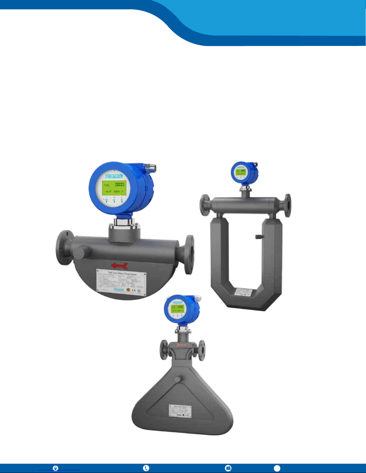
Tek-Cor 1100A
796 Tek Drive, Crystal Lake, IL 60014 USA
+1 847 857 6076 |+1 847 655 7428 +1 847 655 6147
www.tek-trol.com
Page 2
Quick Start Guide
Quick Start Guide
Quick Start Guide
Quick Start Guide
Quick Start Guide
Quick Start Guide
1. Before You Begin
This guide provides basic guidelines to assist you in quickly getting started.
Installation of the transmitter in an explosive environment must be undertaken in accordance with the
appropriate local, national, and international standards, codes, and practices. Review the approvals
section of the Tek-Cor 1100A reference manual for any restrictions associated with a safe installation.
2. Unpack
Tek-Cor 1100A Coriolis Mass Flowmeter x 1
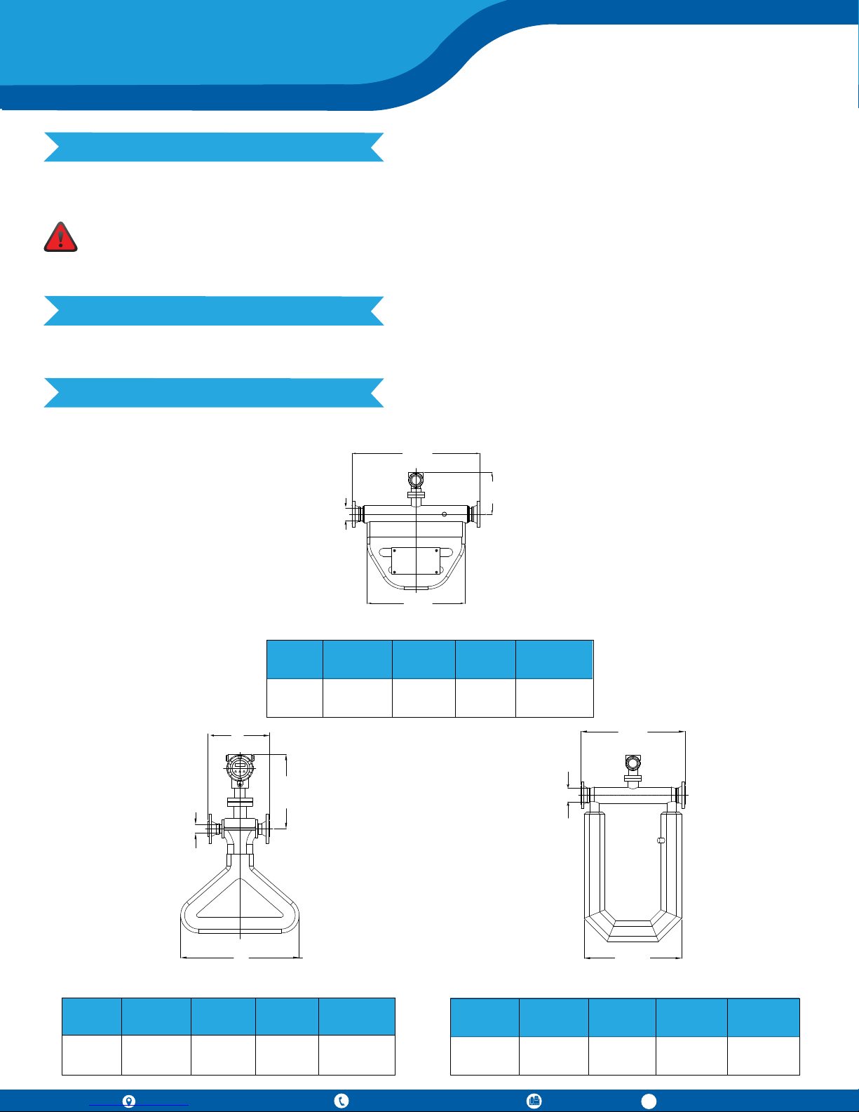
3. Dimensional View
Note: For additional dimensions refer to the detailed manual.
8"
(0.66 ft)
Size
4"
(0.33 ft)
11.02"
(0.91 ft)
4"
(0.33 ft)
L
44.48"
(3.70 ft)
44.48"
(3.70 ft)
33.85"
(2.82 ft)
Micro-Bend
L1
33.85" 25.98"
(2.82 ft)
14.56"
(1.21 ft)
H H1
(2016 ft)
Integrated
14.56"
(1.21 ft)
4"
(0.33 ft)
36.02"
(3 ft)
1"
(0.08 ft)
18"
(1.5 ft)
Triangle-Shaped
Size Size
(0.08 ft) (1.33 ft)
L
8"1"
(0.66 ft)
796 Tek Drive, Crystal Lake, IL 60014 USA
L1 H
18" 16"
(1.5 ft)
H1
Integrated
11.02"
(0.91 ft)
+1 847 857 6076 |+1 847 655 7428 +1 847 655 6147
4"
(0.33 ft)
36.02"
(3 ft)
33.85"
(2.82 ft)
U-Shaped
L
L1 H H1
Integrated
33.85" 50.78" 14"
(2.82 ft)
(4.25 ft)
www.tek-trol.com
(1.16 ft)
Page 3
Technology Solutions
4. Display
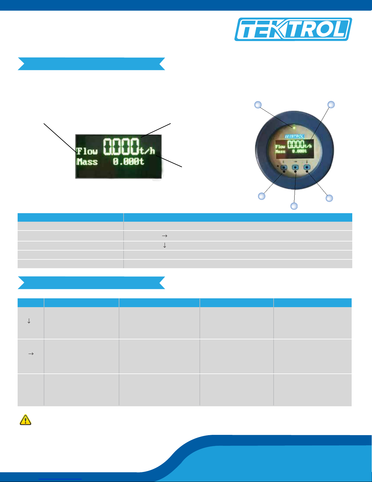
Please use the operation panel of the transmitter to set the configuration, such as basic configuration parameters, zero calibration, and cut-off value of low flow and output range of current frequency.
The panel of the transmitter is shown as below:
Indication of Title
No. Notes
1
2
3
4
5
Indication of Numeric Value
Indication of Units
E key : Enter
key : Move Cursor or Return
key : Page Down
Light for Working Status
Two Line LED
54
1
2
3
5. Key Functions
Key Menu State
E
Measurement State
Show the Measurement
Result and State on Page
1/2/3 of the Display.
Page Down to Menu State.
Return to the Last Screen
-
Next Menu
Return to the Upper-Level
Menu, Press the Key Several
Times to Return to the
Measurement State
Enter the Menu
Operation point of Photoelectric Key is located right behind the glass panel. It is better to operate the
Photoelectric Key in a vertical direction, not a horizontal direction.
Function State
Next Function
Select Function Move the Cursor Right
Confirm and Save the
Function
Date State
Change Number
Change Unit
Change Character
Save the Input Select Yes
or No then Back to Function
Menu
Tek-Cor 1100A
Page 4
Quick Start Guide
Quick Start Guide
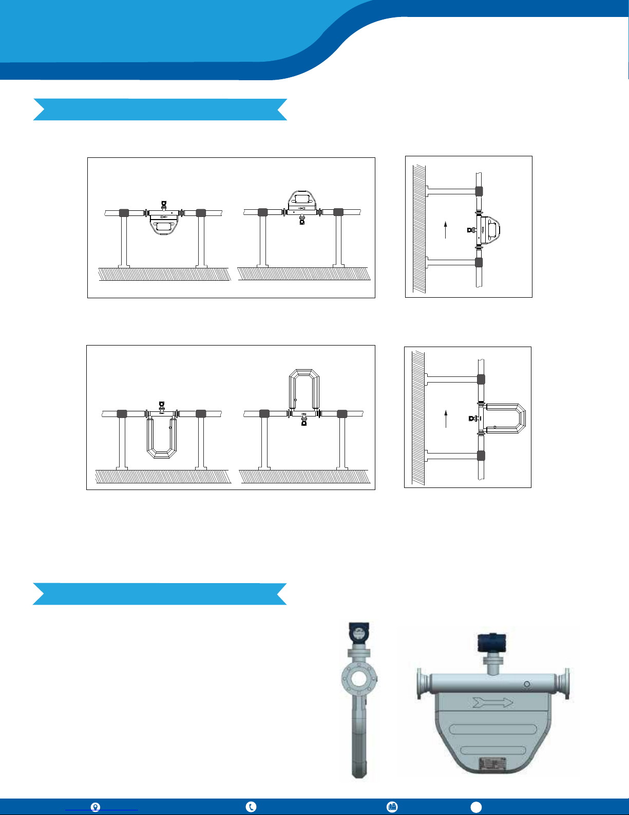
6. Sensor Mounting
Micro-Bend Sensor Mounting
Position A
Recommended Horizontal Installation
U-Shaped Sensor Mounting
Position A
Position B
Position B
FLOW
Vertical Mounting
FLOW
Recommended Horizontal Installation
Vertical Mounting
If the medium contains solid particles, mount the meter as shown in position “A”, and in all other cases mount
the meter as shown in position “B”. Vertical Mounting is recommended, if the medium contains gas bubbles and
solid particles.
7. Transmitter Mounting
Integral Mount
Install the sensor and the transmitter on the pipeline.
The transmitter can be mounted with 90 ° revolutions
depending on the requirement of sensor installation.
796 Tek Drive, Crystal Lake, IL 60014 USA
+1 847 857 6076 |+1 847 655 7428 +1 847 655 6147
www.tek-trol.com
Page 5
Technology Solutions
Remote Mount
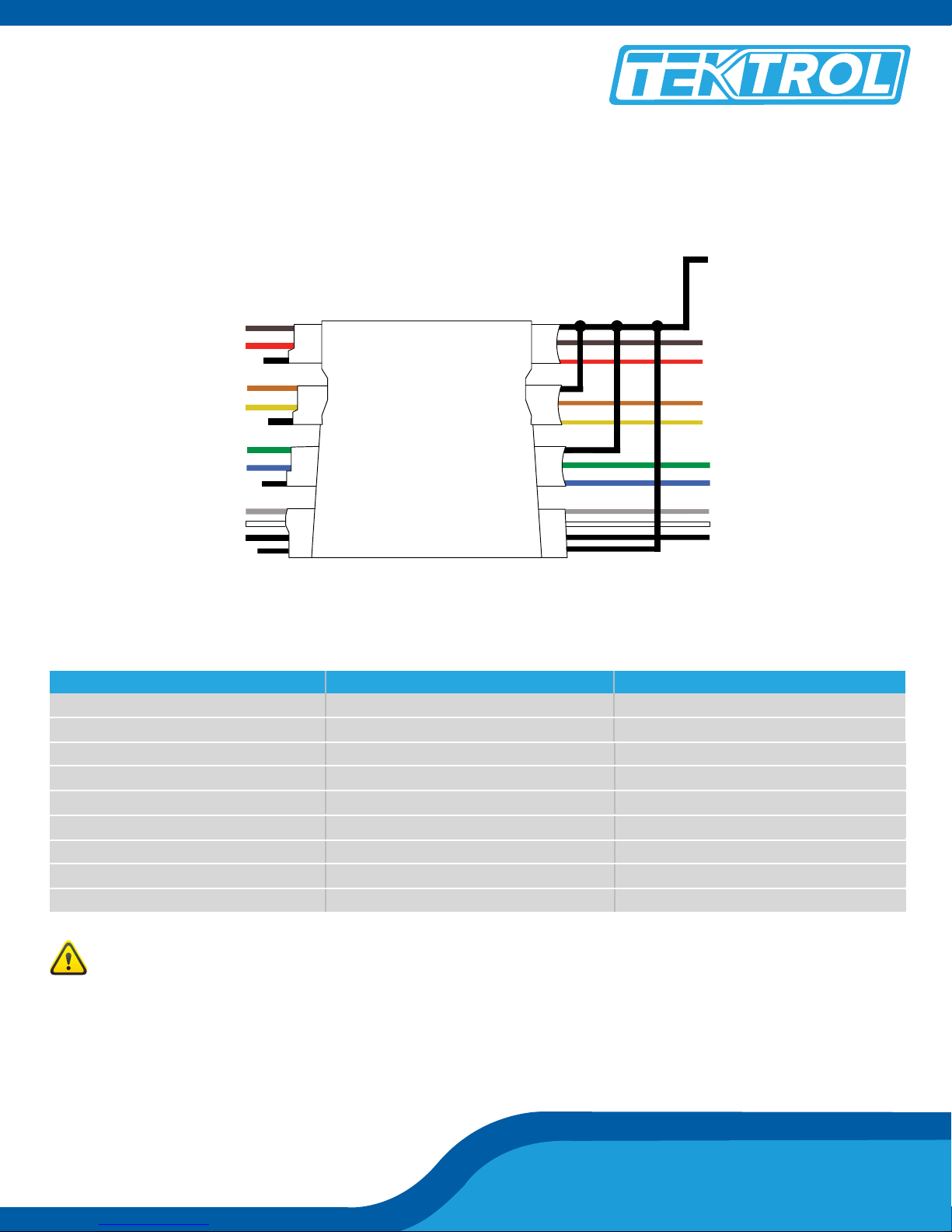
When Tek-Cor 1100A is mounted separately, the sensor and the transmitter should be connected through
special 9-core cable.
Shielded all
wires
Brown
Red
Orange
Yellow
Green
Blue
Gray
White
Black
Brown
Red
Orange
Yellow
Green
Blue
Gray
White
Black
Note: In case of remote mounting, the sensor and the transmitter should be respectively matched with junction
box for connecting the special 9-core cable.
Line No. Line Color Function
1
2
2
3
4
5
6
8
9
Brown
Red
Orange
Yellow
Green
Blue
Grey
White
Black
The Left Coil +
The Left Coil -
The Left Coil +
The Left Coil -
Driving Coil +
Driving Coil -
Temperature +7
Temperature -
Temperature Compensation
Cut off power before connecting cables. The power voltage must match that indicated in the junction
box of the transmitter and the earth connector must be well connected with the earth wire to ensure
its correct safety performance.
Tek-Cor 1100A
Page 6
Quick Start Guide
Quick Start Guide
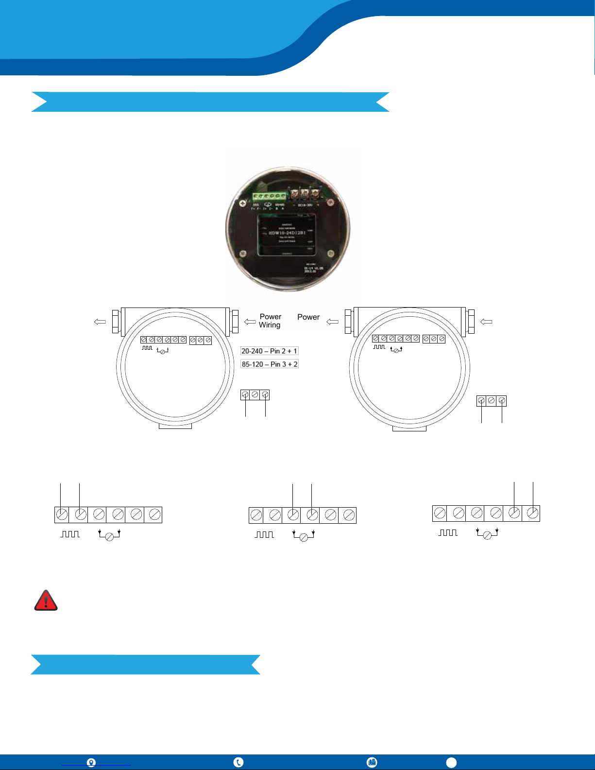
8. Power Supply and Signal Output Wiring
The transmitter can be connected to 85 to 220 VAC or 18 to 28 VDC power supply.
2 1
3
-DC18-30U+
4-20
Power
Wiring
RS 485
Power
Wiring
±20
F+ F - I+ I- B A L N FG
2 1
3
RS 485 - AC85 - 265U
3
AC85-265U
L N FG
AC Power Wiring
4-20
RS 485
F+ F - I+ I- B A
Pulse Output Wiring
F+ F - I+ I- B A
Current Output Wiring
Power
Wiring
2 1
Power
Wiring
4-20
RS 485
2 1
3
±20
RS 485 - DC18-30U +
F+ F- I+ I- B A
DC Power Wiring
F+ F - I+ I- B A
RS485 Output Wiring
Before powering up the flowmeter in a dangerous area, please confirm that the flowmeter’s explosion-proof class is consistent with the environmental requirements in order to avoid potential danger.
Make sure that the power is shut off to avoid electric shock when installing the transmitter. Follow the
installation and operation instruction manualto ensure safe operation.
9. Grounding
Both the sensor and the transmitter have to be grounded correctly; failure to do so may cause a measurement
error and the sensor may not work. If the pipeline is connected with the ground, the transmitter can be grounded through the pipeline; if the pipeline is not connected with the ground, the transmitter should be grounded
independently.
796 Tek Drive, Crystal Lake, IL 60014 USA
+1 847 857 6076 |+1 847 655 7428 +1 847 655 6147
www.tek-trol.com
Page 7
10. Installation
Technology Solutions
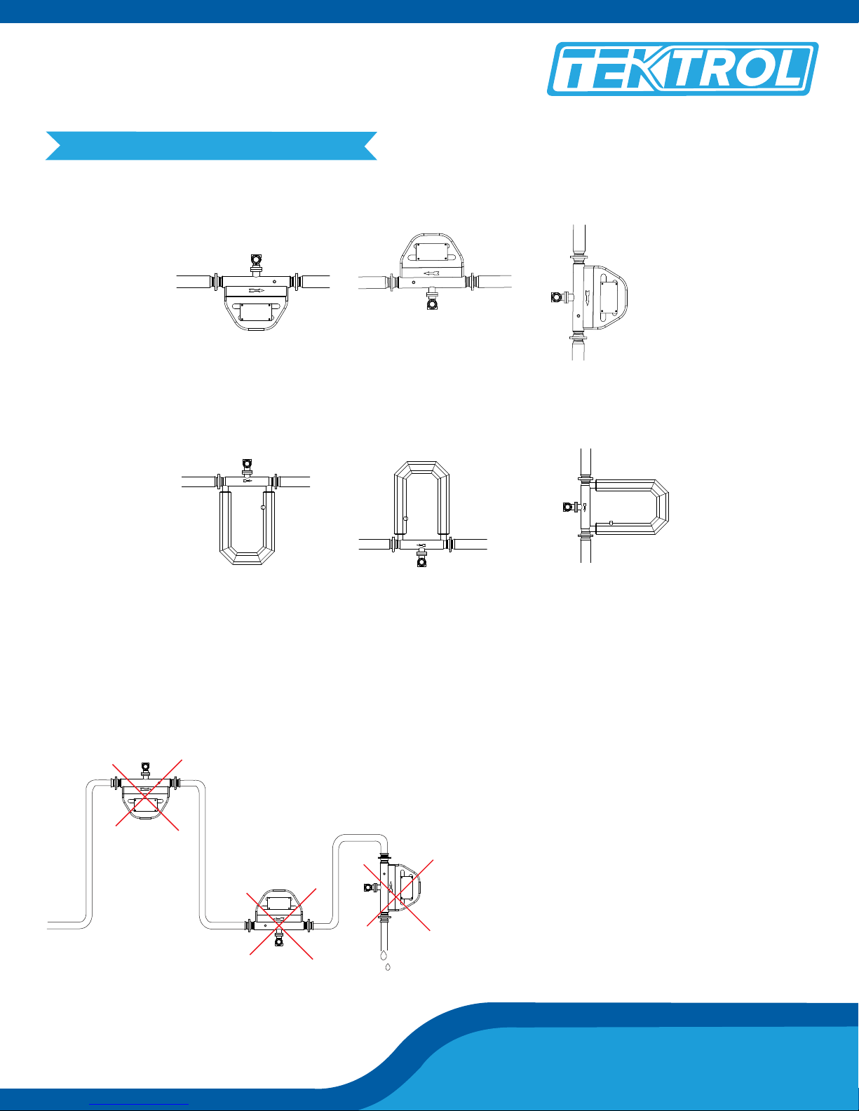
Micro-Bend Series Installation
Picture-1 Picture-2
For Liquid or Slurry
U-Shaped Series Installation
Picture-1 Picture-2
For Liquid or Slurry
For Gas
For Gas
Picture-3
For Liquid or Slurry or Gas
Picture-3
For Liquid or Slurry or Gas
For the horizontal installation, the measuring tube should be installed on the downside of the pipeline when the
process medium is liquid or slurry (shown in Picture 1); on the upside of the pipeline when the process medium
is gas (shown in Picture 2). For vertical installation, the measuring tube should be installed alongside the pipeline when the process medium is liquid, slurry, or gas (shown in Picture 3).
A
The meters must not be mounted at the highest
point of the tubing (A), if gas bubbles are expected.
If solid particles expected, then it should not be
installed at the lowest point (B).
B
C
The meters must not be mounted in a drop line near
the open end (C), as this may cause the meter to run
empty.
Tek-Cor 1100A
Page 8
Quick Start Guide
Quick Start Guide
11. Flow Direction
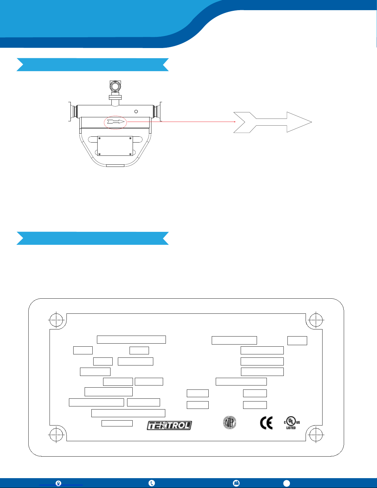
There is a flow arrow which indicates the flow direction in front of the sensor; install the Tek-Cor 1100A accordingly; failure to do may result in the transmitter not displaying the mass flow correctly. If the process medium is
liquid or slurry, the flow direction is down-up; if the process medium is gas, the flow direction can be either
down-up or up-down.
Note: It is recommended that sensor of Tek-Cor 1100A is supported using a rubber connector as the buffer.
12. Calibration
The Tek-Cor 1100A does not need field calibration; it has been calibrated before delivery. Each set of Tek-Cor
1100A has its own instrumental coefficient, including one flow coefficient and four density coefficients (high
density D1, high period K1, low density D2, and low period K2), which will be shown in the nameplate of the
Sensor or Calibration certificate.
Tek-Cor Mass Flowmeter
Model 1100A
Size
1"
Connection
IP Class
Supply Voltage
Ambient
V17101601T5562 2017.06
SN
Ex Marking
2-2-025A-1-1-150-1-G
Accuracy
1.5
IP67
24 VDC 0.4A
4F to 131F
-
Class 1, Div.1,Gr.B,C,D
Tag No.
www.tek-trol.com Crystal Lake, IL60014, USA
0.2
ANSI 300 RF
Flow Range
37 to 881 lb/min
Material (Wetted)
Nominal Pressure
Temperature Range
Flow Cal
D1
0.0012
3663.21
K1
915.740 G/S/US
D2
K2
NTEP CC NO.45-033 E360841
MMQ
316 SS
928 PSI
-58F to 257F
0.9965
3975.42
14 lb.
GPS NJ,USA
GPE 1100A ENGL
796 Tek Drive, Crystal Lake, IL 60014 USA
+1 847 857 6076 |+1 847 655 7428 +1 847 655 6147
www.tek-trol.com
Page 9
Technology Solutions
Zero Calibration
Zero Calibration provides the reference point for the flowmeter. It is necessary to conduct the zero calibration
whenever the Coriolis Meter is installed.
For Zero Calibration, follow the following procedure after installation:
• Warm-up the flowmeter for 30 minutes.
• Once the warm-up is complete, continue the flow through the flowmeter until the temperature of the
flowmeter is same as the working temperature of the fluid.
• When the flowmeter has reached the required temperature, close the downstream valve, and make the
fluid pass through the flowmeter under normal temperature, density and, pressure. Then close the
upstream valve to ensure the sensor is full of liquid during the process of Zero Calibration.
• Carry out the Zero Calibration of the flowmeter.
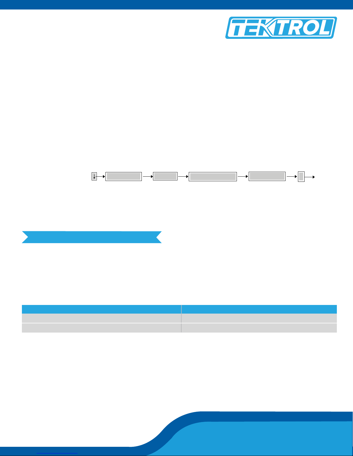
Finally, press
Input password to start zero calibration.
The default password is 000000
Note: Each Zero Calibration lasts 30 seconds and must be repeated at least 10 times.
Configuration
Zero-Cal
Flow Configuration
Zero Correction
E
13. Error Indication
The user can detect a fault in the flowmeter using the LED indicator and LCD displays. Different colors of the
LED lights indicates the working condition of the flowmeter, while the LCD displays can show the self-diagnostic alarm information of the transmitter, which is useful for detecting the malfunctions.
LED Indication
LED Condition Working Condition
Green Light
Red Light
Normal Operation
Error
Note: For additional information refer to the detailed manual.
Tek-Cor 1100A
Page 10
Quick Start Guide
Quick Start Guide
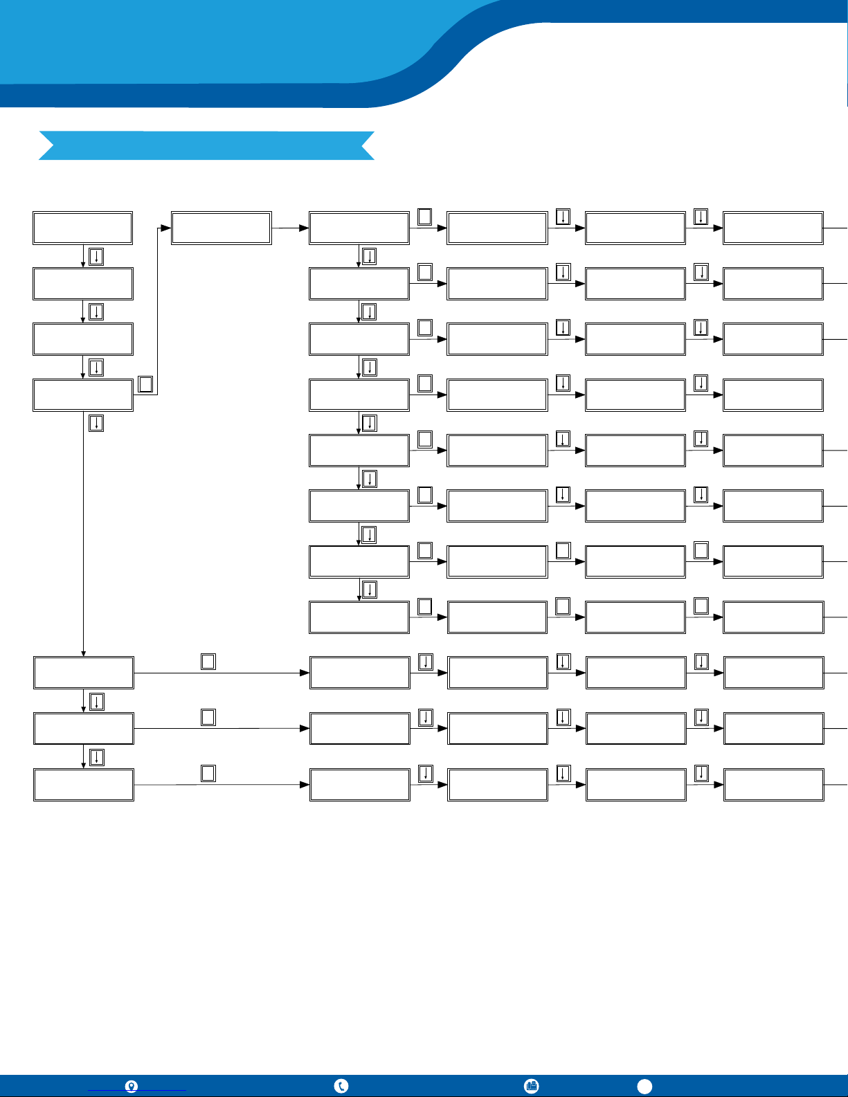
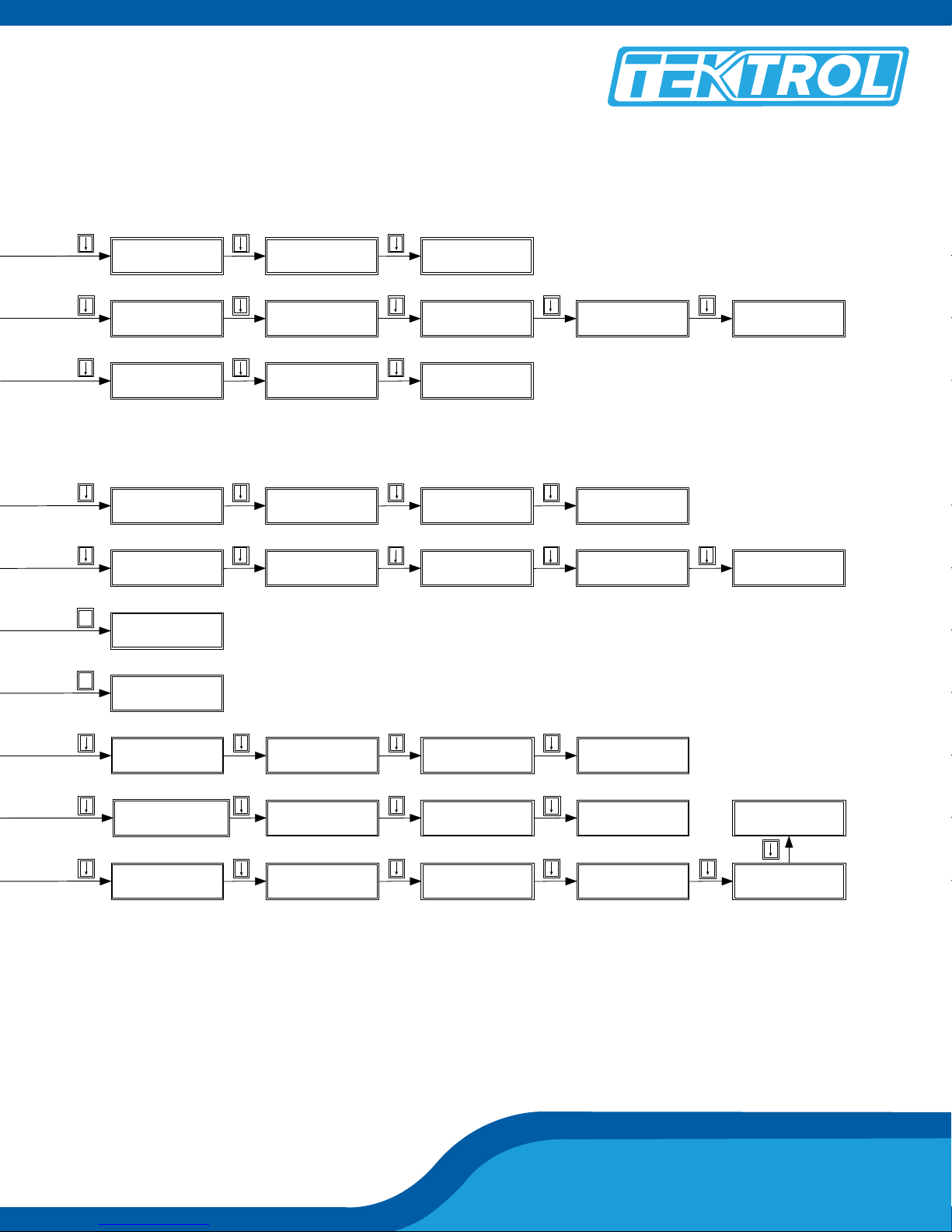
14. Menu Tree
Mass x.xxx t
Flow x.xxx t/h
Volm x.xxx m3
Flow x.xxx m3/h
Den x.xxx g/mL
Temp x.xxx ºC
Configuration
Press E to enter
181716
26 2524
3432 33
414039
4654
5453
898887
8
E
Zero Calibration
x.xxx us
Low Flow Cut off
xxx.x kg/h
Reset Totalizer
Press E to enter
9
E
Pulse Weight
x.xx
Pulse Output
Mass
20mA Value
xxx.x
10
E
Mass Unit
t
Mass Flow Unit
t/h
Volume Unit
m3
11
E
12
13
14
Press Comp Mode
None
44
E
Output AUTO Sim
Press E to enter
52
E
OW AnalyseS witch
OFF
E E E
Enter Old Password
000000
Flow Press Comp Coe
x.xx
Flow Simulate t/h
x.xx
20 °C Oil Den g/mL
x.xxx
Enter New Password
000000
Input Press MPa
xx.xx
Flow Sim Start
Press E to enter
20°C Water Deng/mL
x.xxx
New Password Again
000000
1
Password?
000000
86
Flow Config
Press E to enter
2
Output Config
Press E to enter
3
Unit Config
Press E to enter
4
E
Pressure Comp
Press E to enter
Other
Press E to enter
Add-ons Function
Press E to enter
Change Password
Press E to enter
11010910815
Gas compensation
Press E to enter
E
Gas CompenSwitch
OFF
Gas Compen K1
X.XXXX
EE
Gas Compen K2
X.XXXX
Calibration
Press E to enter
Inner Para
Press E to enter
System Para
Press E to enter
5
E
FlowCal g/s/us
xxx.xx
6
E
Freq xx.xxx Hz
Time x.xxx us
7
E
Temperature Cal
x.xxxx
60
68
76
Temp Correction
x.xx
Drv %
L R V
Temperature Zero
x.xx
H.DensityD2 g/mL
x.xxx
Pred xxxxx.x us
Ind xx.x °C
Density Cal
x.xxxx
H. Period K2 us
xxxxxx.x
PUL: xxxx.x Hz
CUR: xx.x mA
Density Zero
x.xx
636261
717069
797877
796 Tek Drive, Crystal Lake, IL 60014 USA
+1 847 857 6076 |+1 847 655 7428 +1 847 655 6147
www.tek-trol.com
Page 11
Technology Solutions
E
E
Flow Direction
Fwd
Current Output
Mass
Volume Flow Unit
m
Gas Contain Corre
x.xx
PWD Succeed
New PWD 000000
Expect Water Cut
X.XX
3
First Menu
Mass
/h
35
90
111
Mass Inventory t
x.xxx
MODBUS Address
xx
Density Unit
g/mL
4847
Check System State
OFF
W Contain Corre
x.xx
36
VolmInventory m
x.xxx
28 27
Baud Rate
9600
3
29
Parity Bit
None
30
31
Stop Bits
One
37
Temperature Unit
°C
21 2019
Flow Filtering s
1.5
Density Range
OFF
49
Den Filtering s
3.0
Upper Den g/mL
x.xxxx
50
58575655
59
Lower Den g/mL
x.xxxx
L.DensityD1 g/mL
x.xxx
72
Water x.xxx g/mL
Oil x.xxx g/mLL
Menu Language
Eng.
L. Period K1 us
xxxxxx.x
Pressure Comp Coef
Mutipoint Correct
OFF
73
Density Temp Comp
x.xx
YN En kg c 1. 16
9600, 8, N, 1 t 2. 20
Restore Para
Press E to enter
74
67666564
Zero Correction
0
75
Other
83828180
Correction Point
x
85
No X Correct Value
x.xxxx
84
No X Time Value
xxx.x
Tek-Cor 1100A
Page 12

Quick Start Guide
Technology Solutions
796 Tek Drive
Crystal Lake, IL 60014
USA
Tel : +1 847 857 6076, +1 847 655 7428
Fax : +1 847 655 6147
Email: [email protected]
www.tek-trol.com
Tek-Cor 1100A
 Loading...