

Page 1

V1.4
1
TBTC0/1/2/3
OPEN TEM CELLS FOR EMC PRE-COMPLIANCE TESTING
1 Introduction
Radiated emission tests are typically carried out in anechoic chambers, using antennas to pick up the radiated
signals. Due to bandwidth limitations, several antennas are required to cover the complete frequency range.
Furthermore, it requires much space and the cost of the equipment for a standard conformant setup is immense.
An engineer of a small or medium size enterprise usually has to rely on his experience and on best practice
methods in order to design an EMC compliant product. Nevertheless, it is estimated that > 50% of products fail
testing first time around. Anytime an engineer sends a new product for compliance testing, it is a shot in the dark.
Failing is very expensive. Not only that re-testing costs are high, but also the project schedule and market
introduction gets delayed.
What is needed is an affordable laboratory set up to measure radiated emissions in the own lab, prior to compliance
testing. A TEM cell is the right piece of equipment for desktop testing of radiated emissions. Tekbox developed
open TEM cells to cover the complete frequency range up to 2GHz and with usability even at frequencies beyond.
Combined with a spectrum analyzer, products can be tested before and after EMC related design modifications.
A set up with a TEM cell will not deliver exactly the same quantitative results as a measurement in a certified test
house, however it will give an excellent indication on whether the design suffers from excessive radiated noise or
not. The engineer will clearly see, whether his changes improved or deteriorated the EMC performance or whether
it remained unchanged. Using TEM cells eliminates the guesswork.
2 TEM cell
A TEM cell is a stripline device for radiated emissions and immunity testing of electronic devices. It is not a
replacement, but due to its size and cost it is a convenient alternative to measurements in an anechoic chamber.
A TEM cell consists of a septum, the conductive strip in the centre section and walls which are connected to
ground. The geometry is designed to present a 50Ω stripline. The device under test (DUT) is placed in between
the bottom wall and the septum.
The TBTC1/2/3 are so called “open TEM cells”, which got no side walls for convenient placement of the DUT. It
may pick up RF background noise, which however can be taken into account by doing a measurement of the cell
output signal before powering on the DUT.
Tekbox open TEM cells got a better frequency response compared to standard TEM cells of similar size. TEM
cells suffer from higher order wave modes which limit the usable bandwidth. A unique design feature of the Tekbox
TEM cells implements resistance perpendicular to the desired propagation direction of the wave. Consequently
higher order wave modes and resonances are supressed.
The device is supplied together with a 50Ω/25W RF termination and a DC block to protect the spectrum analyzer
or RF receiver input.
Application of TEM cells
Radiated emission tests:
The septum of the TEM cell picks up radiated noise from the DUT, similar to a broadband antenna, and presents
it to the spectrum analyzer or to a receiver input.
Page 2
V1.4
2
TBTC0/1/2/3
OPEN TEM CELLS FOR EMC PRE-COMPLIANCE TESTING
Radiated immunity tests:
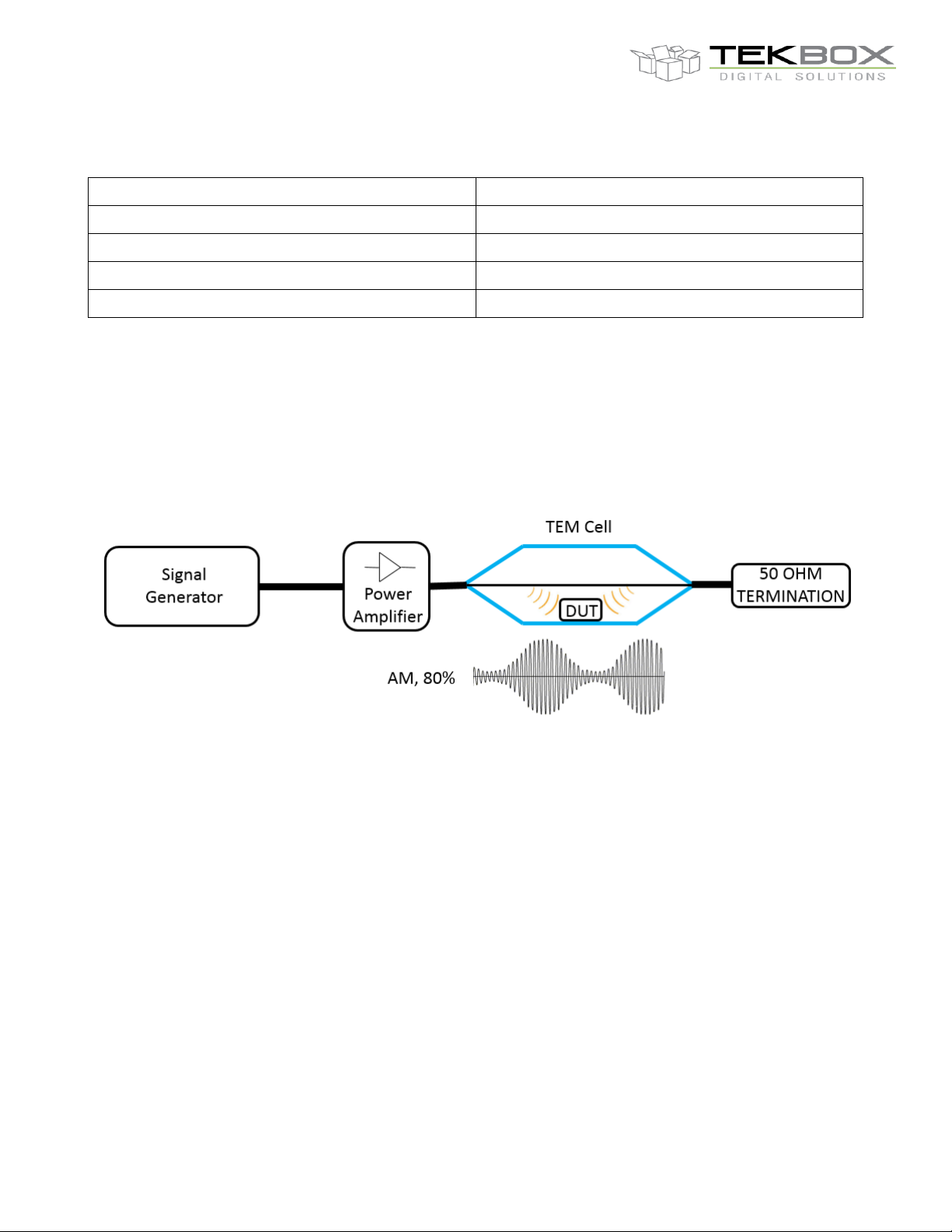
The TEM cell will be connected to the output of a swept signal generator + RF amplifier. The septum radiates the
RF signal into the DUT. The RF signal is typically amplitude or pulse modulated.
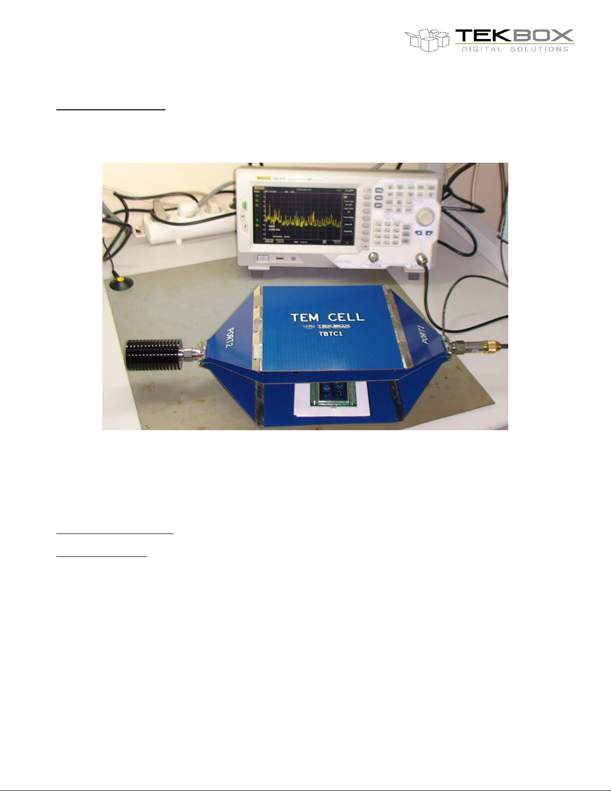
Picture 1 – radiated emission measurement of a controller board using the TBTC1 TEM cell and a Rigol DSA815 spectrum
analyzer
Complete solutions
Following additional equipment may be used for a complete and low cost setup:
Radiated emission testing: Spectrum analyzers such as the RIGOL DSA815 or SIGLENT SSA 3021X
RF immunity testing: RF power amplifiers
Tekbox offers a range of modulated driver / power amplifiers which are ideal for a low cost immunity testing set
up. These amplifiers have built in modulators to generate the required modulation formats and consequently can
be driven by the tracking generator output of spectrum analyzer. Hence, there is no necessity to invest into an RF
signal generator.
Depending on the chosen modulated driver / power amplifier and on the involved TEM cell, fieldstrengths of up to
several hundred Volt can be generated by such a set up.
Refer to the datasheets of the modulated amplifiers for additional information.
Consider that the electric field is oriented orthogonally to the septum. To create a worst case scenario for the DUT,
orient it inside the TEM cell, in order to have the PCB traces oriented orthogonally to the Septum in order to expose
it to the maximum field gradient.
Page 3
V1.4
3
TBTC0/1/2/3
OPEN TEM CELLS FOR EMC PRE-COMPLIANCE TESTING
3 EMC pre-compliance testing with the TBTC0/1/2/3- radiated emissions
Combined with a spectrum analyzer, products can be tested before and after EMC related design modifications.
The engineer will clearly see, whether his changes improved or deteriorated the EMC performance or whether it
remained unchanged. Tem cells eliminate the guesswork.
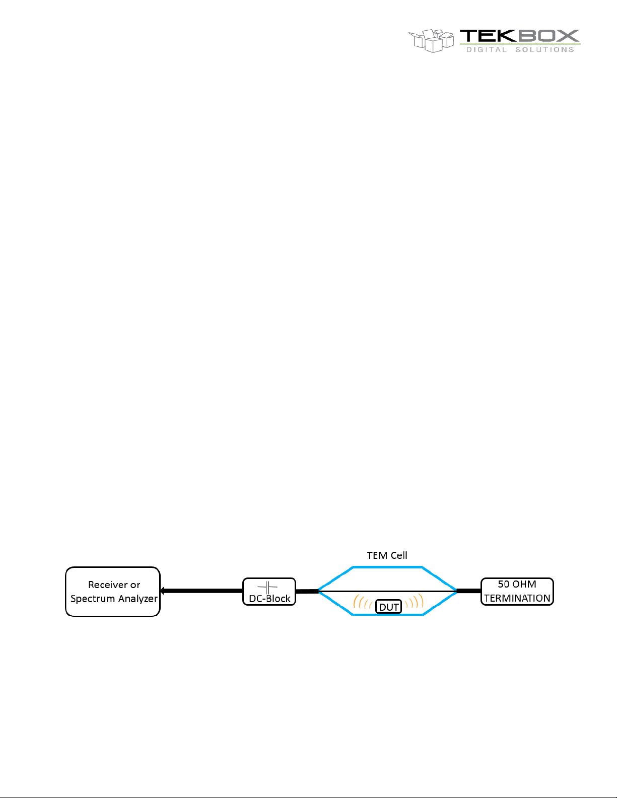
Terminate any of the two ports of the TEM cell with the 50Ω load, connect the DC-Block to the other port and
connect it to the input of the spectrum analyzer or test receiver. Place the DUT under the septum and power it on.
Reduce the input attenuation of the analyzer to 0dB and if available turn on the pre-amplifier to increase the
dynamic range of the measurement. Reduce the resolution bandwidth to 9 kHz or whatever specified in the
corresponding standard. Set the trace to max hold and let the analyzer run as many sweeps as may be necessary
to catch pulsed or sporadic signals from your DUT.
EMC measurements are typically started by performing scans using a peak detector to find problem areas.
Spurious suspected to exceed the limits should then be measured using a quasi-peak detector, if available on
your receiver or spectrum analyzer. A quasi peak detector measures the weighted peak value of the envelope of
a signal. Signals are weighted according to their duration and repetition rate. Signals that occur less frequently will
result in a lower quasi peak value than frequent signals. Due to the nature of this measurement method, quasi
peak measurements consume much more time than simple peak measurements and are often carried out with
reduced span in frequency regions with high amplitude spurious.
The TEM cell can be very effectively used to identify potential issues that may result in failing the compliance test.
As a rule of thumb, given that the PCB is positioned not much higher than 1-2cm above the bottom wall, any
spurious with amplitudes higher than 40dµV are a threat.
A quick check to ensure that spurious are not picked up from outside is done by powering off the DUT. Despite its
construction, the TEM cell is not very sensitive to signals from outside. However cables connected to the DUT
may pick up background noise and guide it into the TEM cell. This signals are usually also present with the DUT
powered off and consequently can be easily identified. Take a screenshot of the radiated spectrum, modify your
design, and check if it improved. Any reduction of spurious level measured in the TEM cell, will also translate into
a reduction of the spurious level measured in the test house.
When failing a compliance test, measure it in the TEM cell and save the results before carrying out any
modifications. Compare the spurious levels documented in the compliance test report versus the spurious levels
measured in the TEM cell. Check how many dB´s are missing to pass the test. Modify/improve the device until the
spurious level measured inside the TEM cell dropped accordingly.
Picture 2 – radiated emission measurement set up
Page 4
V1.4
4
TBTC0/1/2/3
OPEN TEM CELLS FOR EMC PRE-COMPLIANCE TESTING
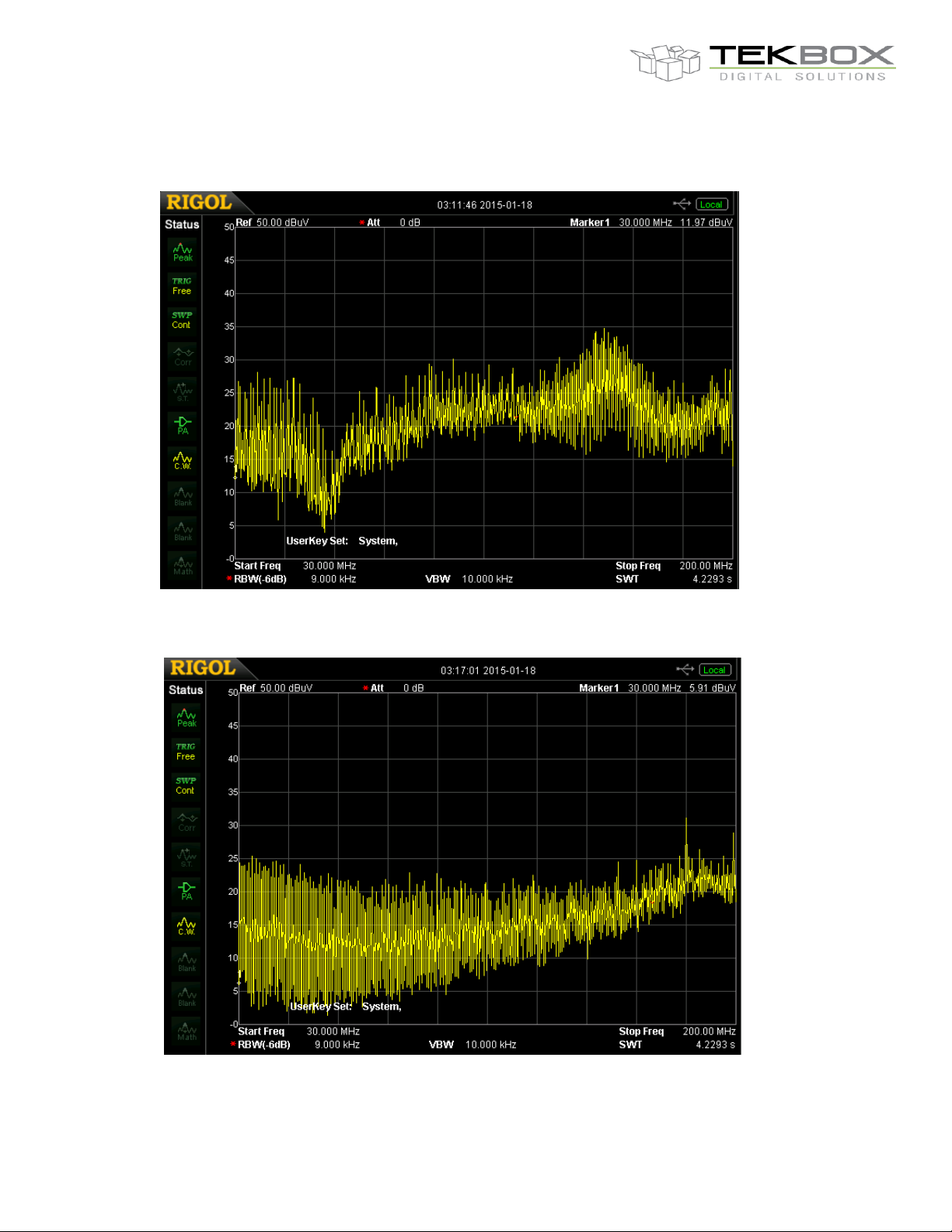
Example of radiated emission measurements before and after modification
Picture 3 – TBTC1, radiated emissions of a LED lamp prototype
Picture 4 – TBTC1, radiated emissions of a LED lamp prototype after modification. The spurious level in the measured
frequency range could be reduced by 10dBµV. The spurious crossing 30dBµV was identified as picked up from outside.
Page 5
V1.4
5
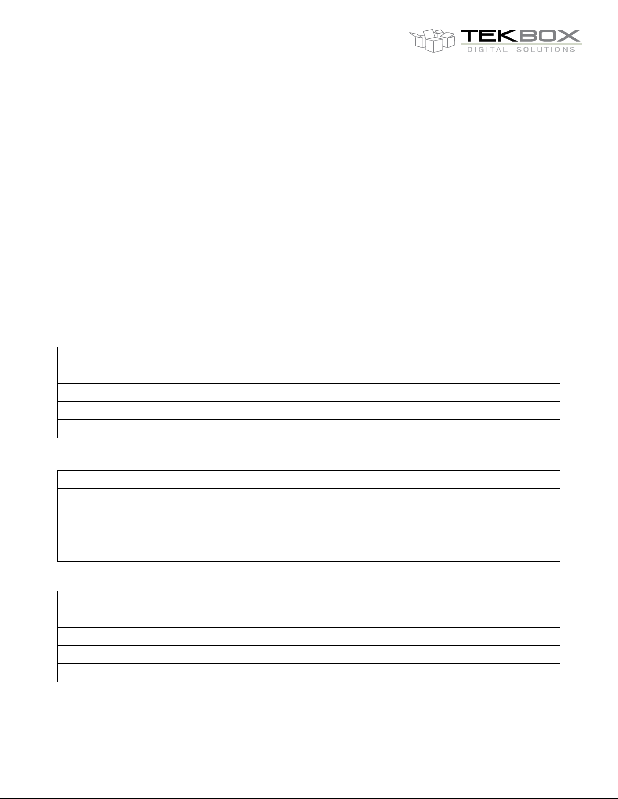
TBTC0, applied RF power
Maximum field strength between septum and wall
10W (40 dBm)
799 V/m
1 W (30 dBm)
253 V/m
0.1 W (20 dBm)
82 V/m
0.01 W (10dBm)
25 V/m
TBTC1, applied RF power
Maximum field strength between septum and wall
10W (40 dBm)
447 V/m
1 W (30 dBm)
141 V/m
0.1 W (20 dBm)
44 V/m
0.01 W (10dBm)
14 V/m
TBTC2, applied RF power
Maximum field strength between septum and wall
10W (40 dBm)
224 V/m
1 W (30 dBm)
71 V/m
0.1 W (20 dBm)
22 V/m
0.01 W (10dBm)
7 V/m
TBTC0/1/2/3
OPEN TEM CELLS FOR EMC PRE-COMPLIANCE TESTING
4 EMC pre-compliance testing with the TBTC1/2/3 - immunity to radiated
signals
The E-field (V/m) between septum and lower (upper) wall of the TBTC1 is
E = V/d where V is the RMS voltage of the applied signal and d is the distance between septum and lower (upper)
wall. This is based on the simplified assumption that the E field would be perfectly homogenous/evenly distributed.
A more practical formula is E = V*Cor/d where Cor is a correction factor for the average field strength over the
volume of the DUT derived from the analysis of the field distribution over the cross section of the cell.
Assuming the DUT is placed in the center of the cell and in the middle between bottom wall and septum, we can
however use the simplified formula with sufficient accuracy.
d = 2.8 cm E = (√(P*50Ω))*35.7
d = 5 cm E = (√(P*50Ω))*20
d = 10 cm E = (√(P*50Ω))*10
d = 15 cm E = (√(P*50Ω))*6.66
Table 1 – TBTC0, field strength vs. RF power
Table 2 – TBTC1, field strength vs. RF power
Table 3 – TBTC2, field strength vs. RF power
Page 6
V1.4
6
TBTC3, applied RF power
Maximum field strength between septum and wall
10W (40 dBm)
148 V/m
1 W (30 dBm)
47 V/m
0.1 W (20 dBm)
14 V/m
0.01 W (10dBm)
5 V/m
TBTC0/1/2/3
OPEN TEM CELLS FOR EMC PRE-COMPLIANCE TESTING
Table 4 – TBTC3, field strength vs. RF power
Terminate any of the two ports of the TEM cell with the 50Ω RF-termination, and connect the other port to a swept
frequency generator / RF power amplifier. Place the DUT under the septum and power it on. Sweep the frequency
and observe the behavior of the DUT. The field decreases with approximately 30dB/m outside the cell, hence it is
uncritical to operate it in ordinary facilities.
Picture 5 – RF immunity measurement set up
Picture 3 shows a “minimum set-up” for immunity testing. Test houses would furthermore insert a directional
coupler in between the power amplifier and the TEM Cell and monitor forward and reflected power.
EMC standards differ largely with respect to the applied field strength. Standards for industrial electronics such as
EN61000-6-4 specify 10V/m (prior to the application of modulation) whereas individual standards of automotive
manufacturers may specify a field strength as high as 400V/m. The required field strength determines the
requirements for the RF power amplifier as listed in tables 1 to 3. Certain standards specify the RF signal to be
amplitude modulated, others specify pulse modulation.
Page 7

V1.4
7
TBTC0/1/2/3
OPEN TEM CELLS FOR EMC PRE-COMPLIANCE TESTING
5 Technical data
TEM Cell TBTC0
TEM cell dimensions:
Length: 390 mm Width: 100 mm Height: 62 mm Septum height: 28 mm
Rectangular area under the septum: 19 cm x 7 cm x 2.8 cm
TEM cell connectors: N-female
Nominal cell impedance: 50 Ohm
Wave impedance: 377 Ohm
Maximum RF input power: 10W (limited by supplied 50 Termination)
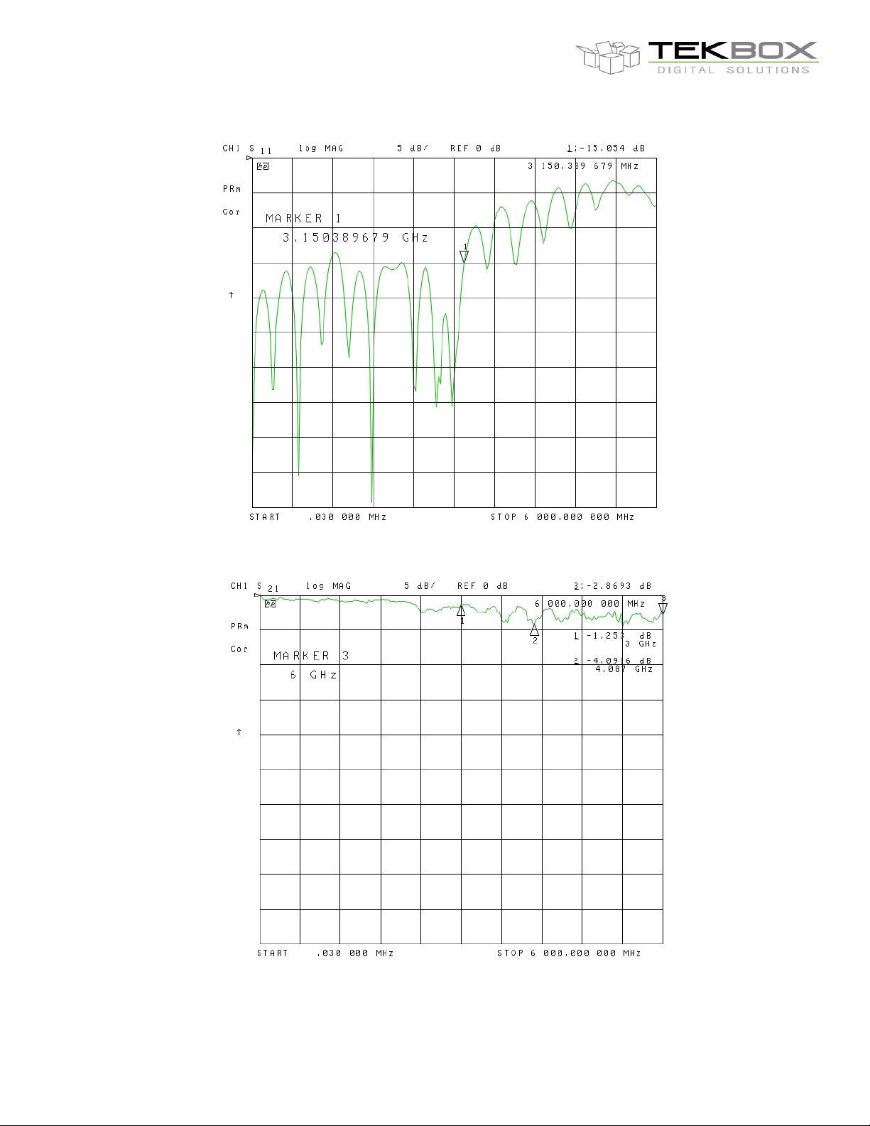
Input return loss: S11 up to 3.15 GHz < -15dB
Transmission loss: up to 3 GHz < 3 dB, up to 6 GHz < 4dB
TEM Cell TBTC1
TEM cell dimensions:
Length: 390 mm Width: 200 mm Height: 108 mm Septum height: 50 mm
Rectangular area under the septum: 19 cm x 13 cm x 5 cm
TEM cell connectors: N-female
Nominal cell impedance: 50 Ohm
Wave impedance: 377 Ohm
Maximum RF input power: 25W (limited by supplied 50 Termination)
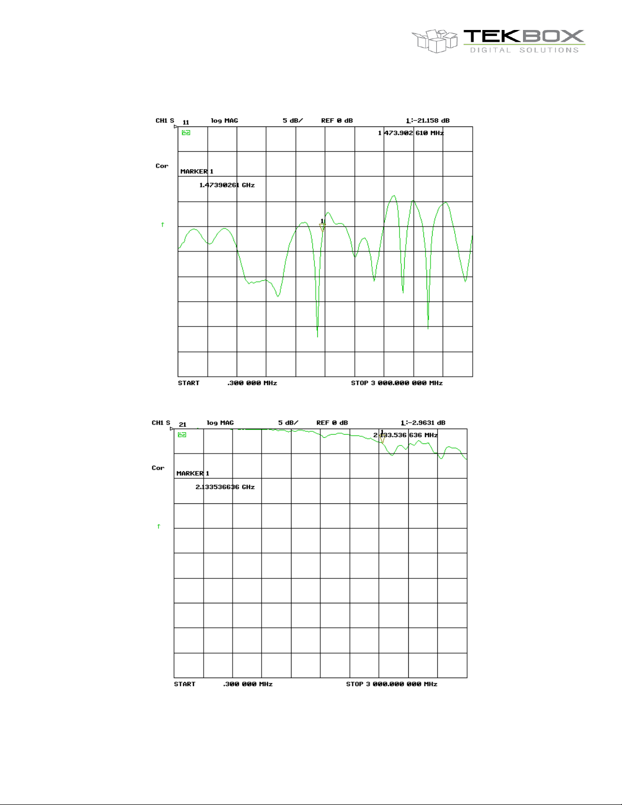
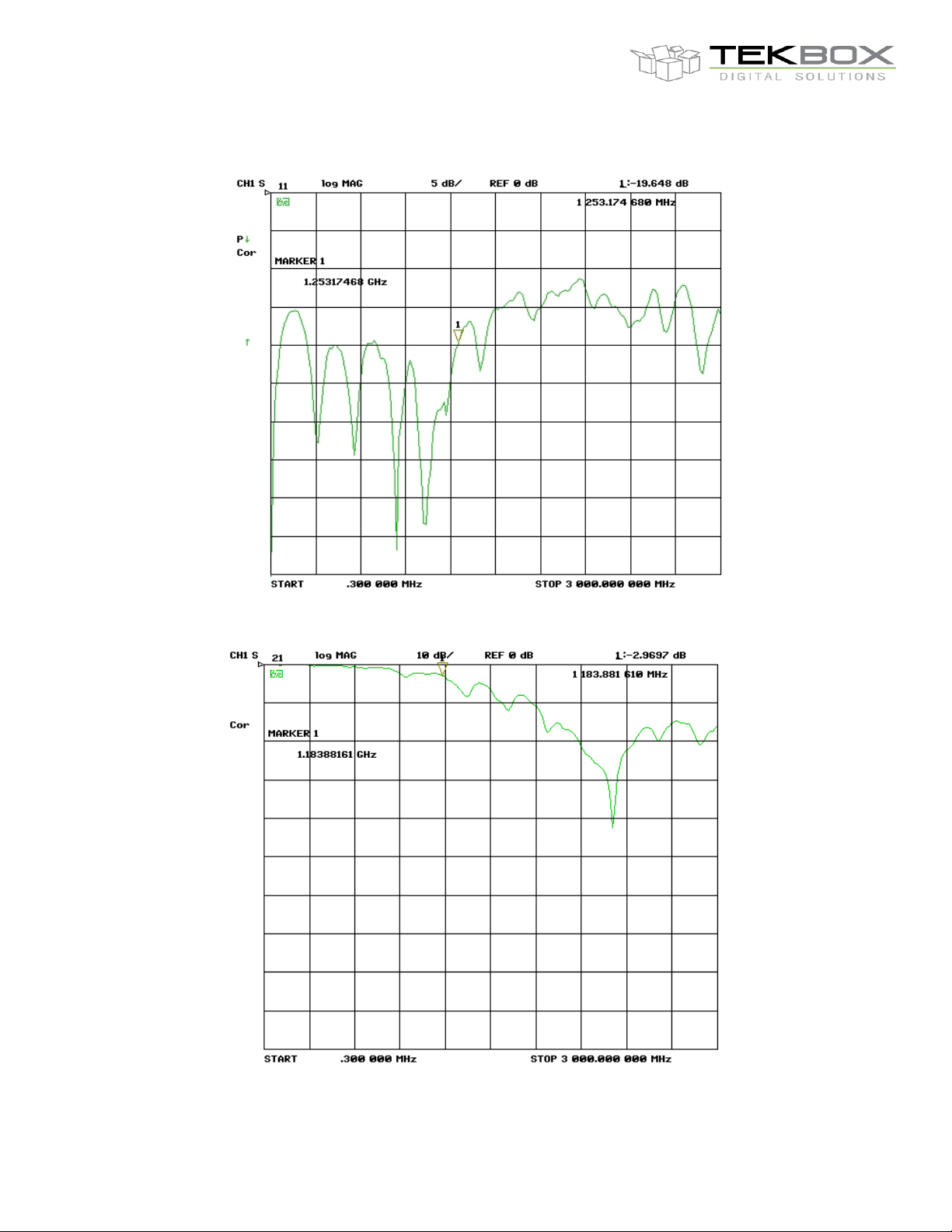
Input return loss: S11 up to 1.2 GHz < -20dB, up to 2.1 GHz < -17dB, up to 3GHz < -14dB
Transmission loss: up to 1.4 GHz < 1 dB, up to 2.1 GHz < 3dB, up to 3 GHz < 6dB
TEM Cell TBTC2
TEM cell dimensions:
Length: 636 mm Width: 300 mm Height: 205mm Septum height: 100 mm
Rectangular area under the septum: 23 cm x 28 cm x 10 cm
TEM cell connectors: N-female
Nominal cell impedance: 50 Ohm
Wave impedance: 377 Ohm
Maximum RF input power: 25W (limited by supplied 50 Termination)
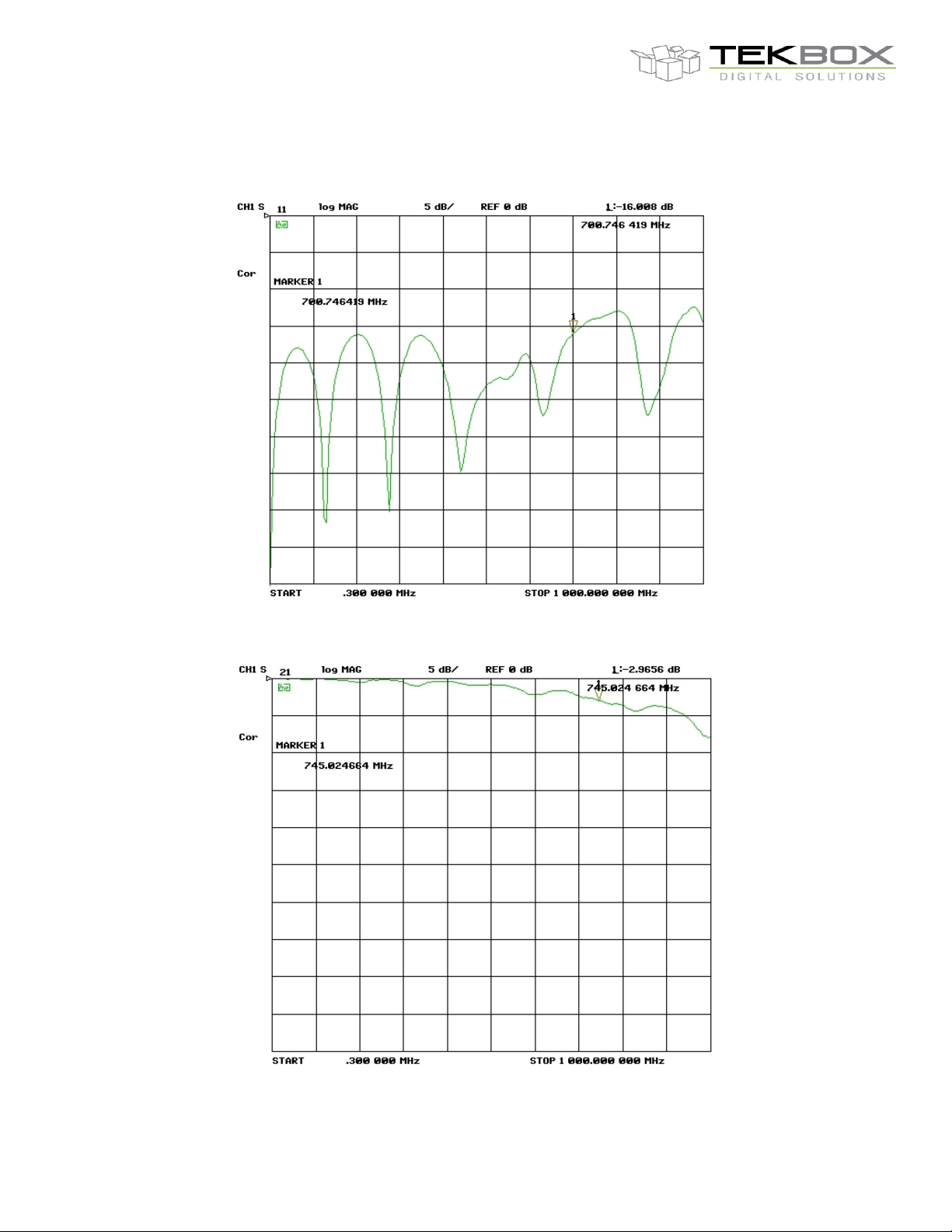
Input return loss: S11 up to 800 MHz < -15dB, up to 1.5 GHz < -10dB, up to 3GHz < -8dB
Transmission loss: up to 800 MHz < 1 dB, up to 1.15 GHz < 3dB
Page 8
V1.4
8
Frequency [MHz]
0.3
0.7 1 10
100
1000
3000
Insertion loss [dB]
7.5 3 1.5
0.02
0.02
0.06
0.2
TBTC0/1/2/3
OPEN TEM CELLS FOR EMC PRE-COMPLIANCE TESTING
TEM Cell TBTC3
TEM cell dimensions:
Length: 1038 mm Width: 501 mm Height: 305mm Septum height: 150 mm
Rectangular area under the septum: 36 cm x 48 cm x 15 cm
TEM cell connectors: N-female
Nominal cell impedance: 50 Ohm
Wave impedance: 377 Ohm
Maximum RF input power: 25W (limited by supplied 50 Termination)
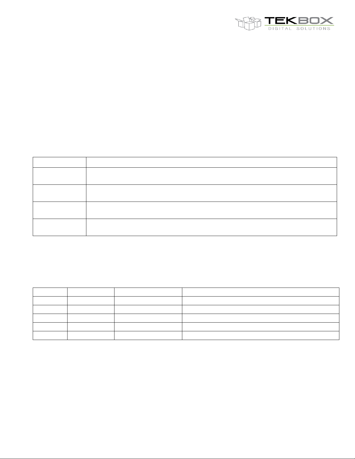
Input return loss: up to 700 MHz < -16 dB
Transmission loss: up to 730 MHz < 3dB
DC-Block 50V-6GHz-N
Connectors: N-Male/Female
Nominal impedance: 50 Ohm
Max. continuous RF power: 2W
Max. continuous RF voltage: 50V RMS
Frequency: 500kHz to 6 GHz VSWR: ≤ 1.2
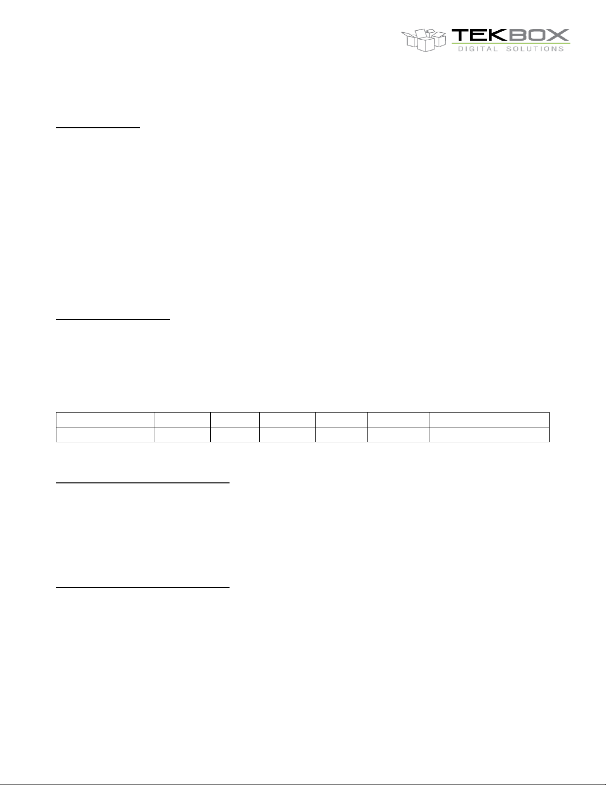
Insertion loss:
Table 1 – DC-Block frequency response
RF-Termination 50Ω-3GHz-25W-N
Connector: N-Male
Nominal impedance: 50 Ohm
Max. continuous RF power: 25W
Frequency: DC to 3 GHz VSWR: ≤ 1.2
Third order intermodulation: ≤ 120 dBc
RF-Termination 50Ω-6GHz-10W-N
Connector: N-Male
Nominal impedance: 50 Ohm
Max. continuous RF power: 25W
Frequency: DC to 6 GHz VSWR: ≤ 1.2
Third order intermodulation: ≤ 120 dBc
Page 9
V1.4
9
TBTC0/1/2/3
OPEN TEM CELLS FOR EMC PRE-COMPLIANCE TESTING
Picture 6 – TBTC0, input return loss
Picture 7 – TBTC0, transmission loss
Page 10
V1.4
10
TBTC0/1/2/3
OPEN TEM CELLS FOR EMC PRE-COMPLIANCE TESTING
Picture 8 – TBTC1, input return loss
Picture 9 – TBTC1, transmission loss
Page 11
V1.4
11
TBTC0/1/2/3
OPEN TEM CELLS FOR EMC PRE-COMPLIANCE TESTING
Picture 10 – TBTC2, input return loss
Picture 11 – TBTC2, transmission loss
Page 12
V1.4
12
TBTC0/1/2/3
OPEN TEM CELLS FOR EMC PRE-COMPLIANCE TESTING
Picture 12 – TBTC3, input return loss
Picture 13 – TBTC3, transmission loss
Page 13
V1.4
13
Part Number
Description
TBTC0
Open TEM cell, 28mm septum height, Termination 50Ω-6GHz-10W-N, DC-Block 50V-6GHz-N,
N-Male to N-Male coaxial cable
TBTC1
Open TEM cell, 50mm septum height, Termination 50Ω-3GHz-25W-N, DC-Block 50V-6GHz-N,
N-Male to N-Male coaxial cable
TBTC2
Open TEM cell, 100mm septum height, Termination 50Ω-3GHz-25W-N, DC-Block 50V-6GHz-N,
N-Male to N-Male coaxial cable
TBTC3
Open TEM cell, 150mm septum height, Termination 50Ω-3GHz-25W-N, DC-Block 50V-6GHz-N,
N-Male to N-Male coaxial cable
Version
Date
Author
Changes
V1.0
14.04.2016
Mayerhofer
Creation of the document
V1.1
30.06.2016
Mayerhofer
Update TBTC3
V1.2
12.02.2016
Mayerhofer
Update TBTC0
V1.3
2.06.2018
Mayerhofer
Information concerning amplifiers for immunity testing
V1.4
17.06.2019
Mayerhofer
Chapter 2 and chapter 5 updated
TBTC0/1/2/3
OPEN TEM CELLS FOR EMC PRE-COMPLIANCE TESTING
6 Warning
Keep the DUT insulated from the septum and cell walls. Insert the
DC-block to get additional input protection for the spectrum
analyzer or measurement receiver.
7 Ordering Information
8 History
Table 2 – Ordering Information
Table 3 – History
 Loading...