

Page 1
V1.4
1
TBST-120/60/60/2; -86/49/45/1; -86/49/45/2
Shielded Tents
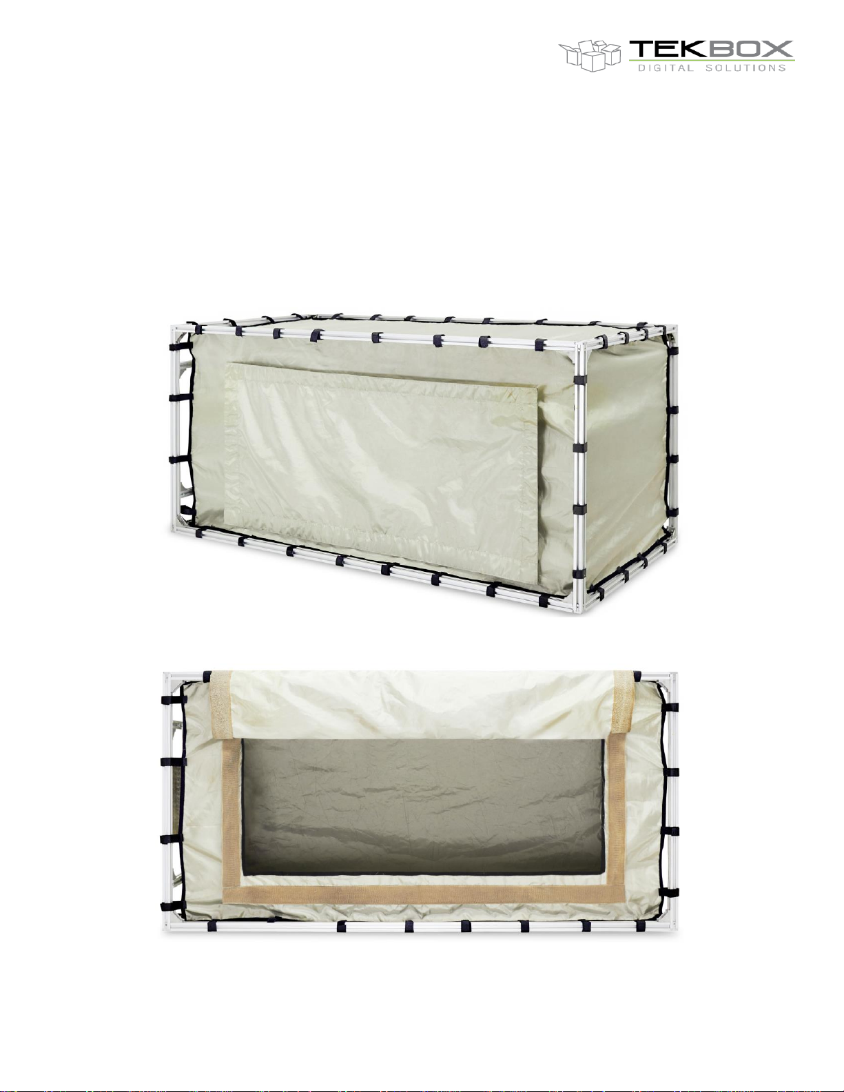
The TBST line of shielded tents is designed to suppress interference from ambient noise
when carrying out EMC pre-compliance measurements. With sizes of 120 cm x 60 cm x 60
cm or 86 cm x 49 cm x 45 cm, it can accommodate any Tekbox pre-compliance test
equipment such as LISNs or TEM-cells.
The shielded tents are composed of two layers of conductive fabrics. It is supported by rigid
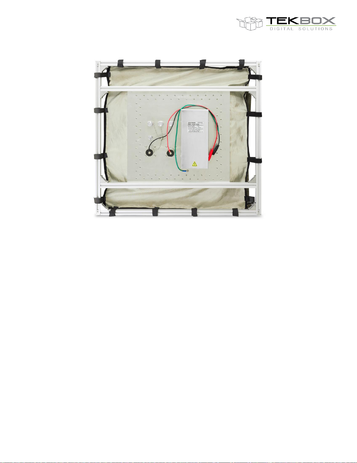
aluminium profiles. The filter panel at the side provides a 240V/10A mains AC filter (optional
for the smaller tent), two general purpose 240V/10A AC/DC filters and four coaxial feed
through adapters with screw caps. The access opening is sealed with conductive Velcro tape.
Picture 1: shielded tent with closed opening
Picture 2: shielded tent with access opening
Page 2
V1.4
2
TBST-120/60/60/2; -86/49/45/1; -86/49/45/2
Shielded Tents
Picture 3: side view with filter panel
1 Warning
Make sure that your set up prevents main phase getting into contact with the metal
parts/fabrics of the tent. Always connect protective earth to avoid any hazard of electrical
shock.
2 Specification
Outer dimensions: 120 cm x 60 cm x 60 cm (86 cm x 49 cm x 45 cm)
Opening dimensions: 85 cm x 35 cm (40 cm x 22 cm)
Frame: 20 mm x 20mm extruded aluminium profiles
Shielding: 2 layers of conductive fabrics
Seal: conductive Velcro tape
Suspension: Velcro stripes
Filter panel: 1 x 240V/10A AC filter; IEC socket (optional for the smaller tent)
2 x 240V/10A AC/DC filter; cables with female Banana couplers
3 x N- female feed through connector with screw caps
1 x BNC-female feed through connector with screw caps
Internal AC socket: pigtail cable with detachable female Schuko
Attenuation: ~ 50 dB in the range DC to 1.5 GHz
Weight: 10.8 kg (6.7 kg / 8.7 kg)
Page 3
V1.4
3
TBST-120/60/60/2; -86/49/45/1; -86/49/45/2
Shielded Tents
3 Sample Plots
3.1 Example: Whip antenna
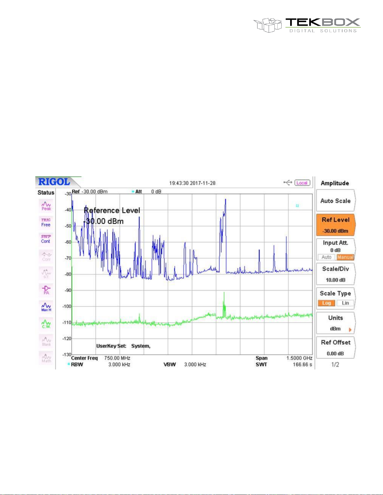
The ambient noise spectrum plot below was taken with a whip antenna outside of the shielded tent (blue graph)
and inside of the shielded tent (green graph). The green graph was taken with lower resolution bandwidth in
order to reduce the base noise level of the spectrum analyzer.
The spectrum plot clearly shows the attenuation of the shielded tent.
Picture 4: ambient noise outside (blue) and inside the tent (green)
Page 4
V1.4
4
TBST-120/60/60/2; -86/49/45/1; -86/49/45/2
Shielded Tents
3.2 Example: Conducted noise measurement
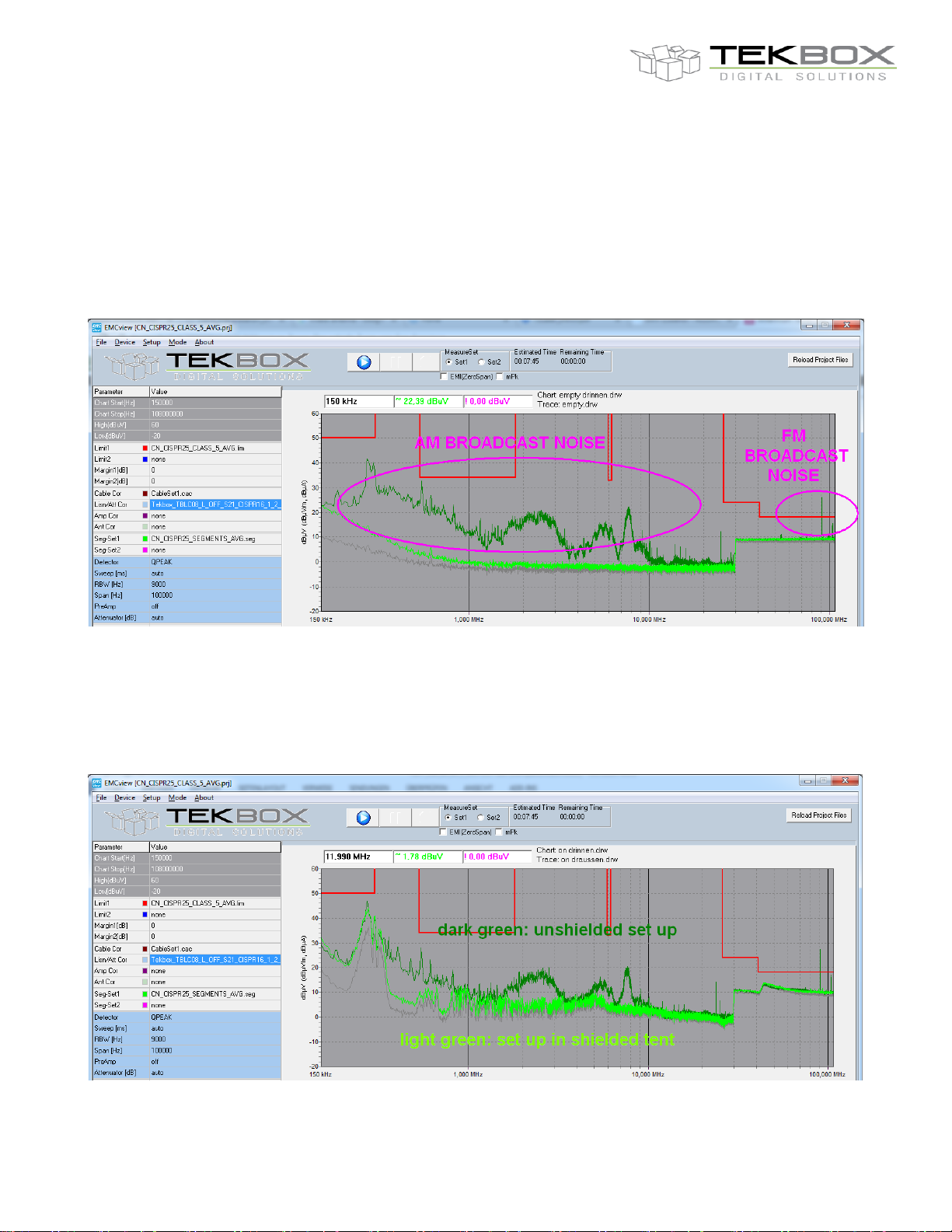
The dark green graph below shows the measured spectrum of a non-powered DUT in a CISPR 25 conducted
noise measurement setup. The DUT connects to the TBOH01 5µH LISN with a very short supply cable (10cm).
The cable between LISN and DUT and the DUT PCB itself already pick up significant ambient noise from AM
and FM broadcast stations.
The light green line shows the results of the same arrangement, with the DUT and LISN placed inside the
shielded tent.
Picture 5: CISPR 25 conducted noise measurement; DUT not powered
The graphs below show the conducted noise spectrum of the powered DUT. In the unshielded set up, all
emissions, except the first harmonic of the DUT and conducted noise between 40MHz and 50MHz, are hidden
under the ambient noise level. An accurate measurement would not be possible without a shielded set up.
Picture 6: CISPR 25 conducted noise measurement; DUT powered
Page 5
V1.4
5
TBST-120/60/60/2; -86/49/45/1; -86/49/45/2
Shielded Tents
4 Assembly
Note that it is not necessary to slide the profile nuts into the profile groves upfront. The nuts can be positioned
and inserted in-line with the groves. When tightening the nuts, they rotate 90° and lock in a right angle with
respect to the direction of the grove.
The frame consists of 10 pieces aluminum profiles with 60 (45) cm length and 4 pieces aluminum profiles with
120 (82) cm length.
Note that there are two types of screws. The shorter type is used to attach the filter plate to the frame.
Step 1:
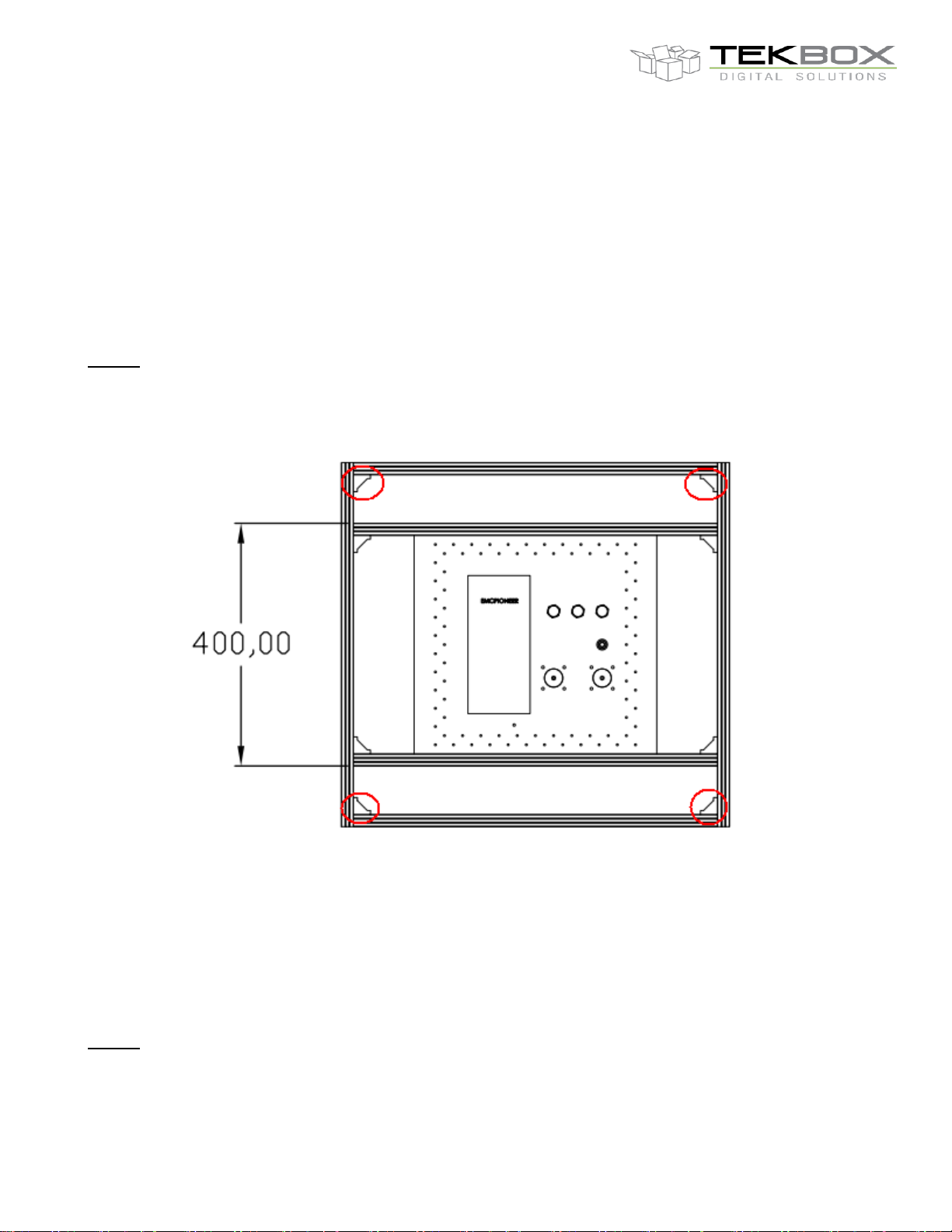
Assemble the left side frame which supports the filter plate first. Attach six pieces 60 (44) cm aluminum profiles
to each other according to the picture below.
Picture 7: left side frame
Note that the filter plate is just displayed for reference purpose. The filter plate comes pre-assembled with the
tent fabrics and is attached after completion of the frame.
80 cm tent: Do not assemble the edge elements highlighted in picture 7. Assemble the top and bottom profiles
in step 3. They will be fastened with edge elements in the horizontal plane only.
Step 2:
Assemble the right side frame similar as in step 1, using 4 pieces 60 (44) cm aluminum profiles
Page 6
V1.4
6
TBST-120/60/60/2; -86/49/45/1; -86/49/45/2
Shielded Tents
Step 3:
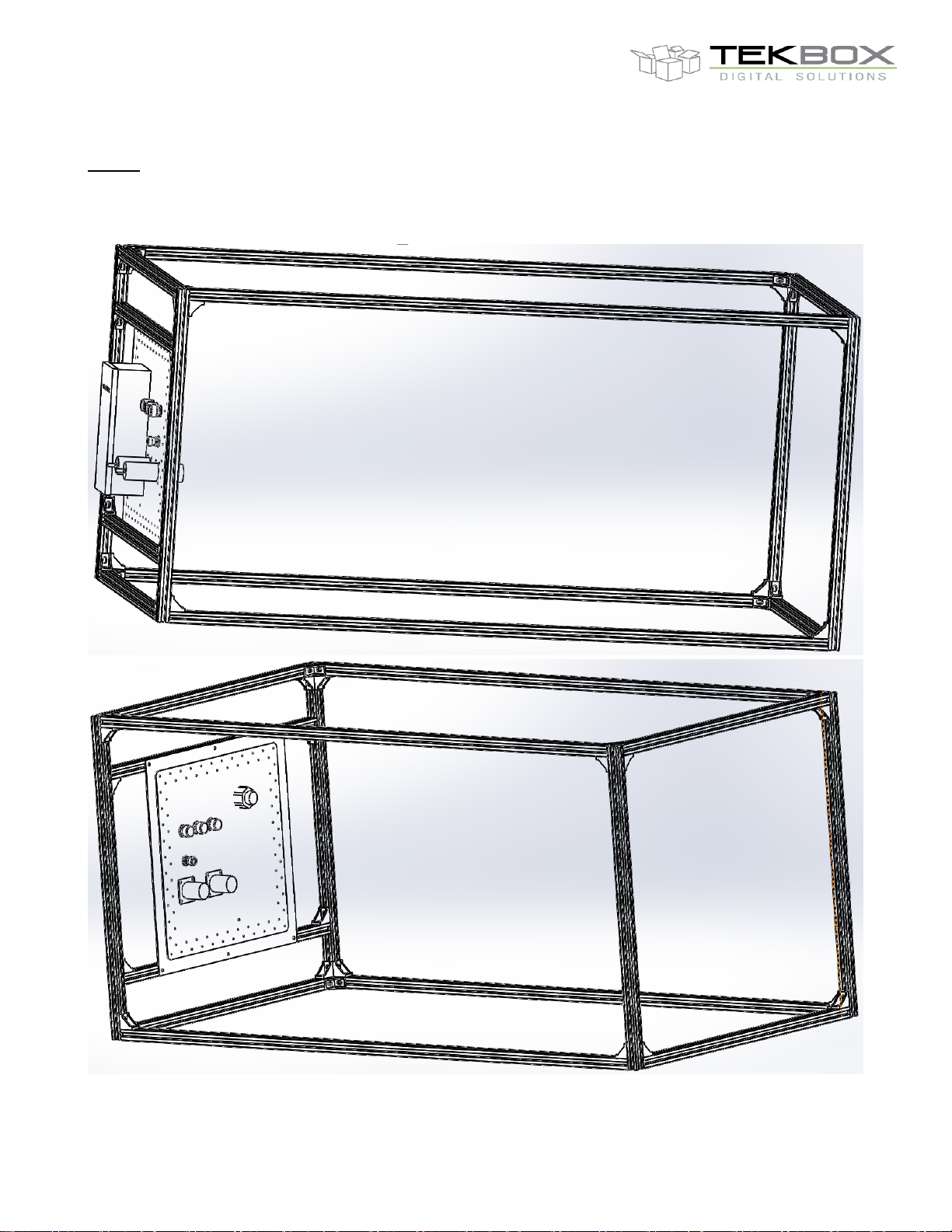
Complete the frame by connecting the two side frames with 4 pieces 120 (84) cm aluminum profiles.
Picture 8: completed frame
Page 7
V1.4
7
TBST-120/60/60/2; -86/49/45/1; -86/49/45/2
Shielded Tents
Step 4:
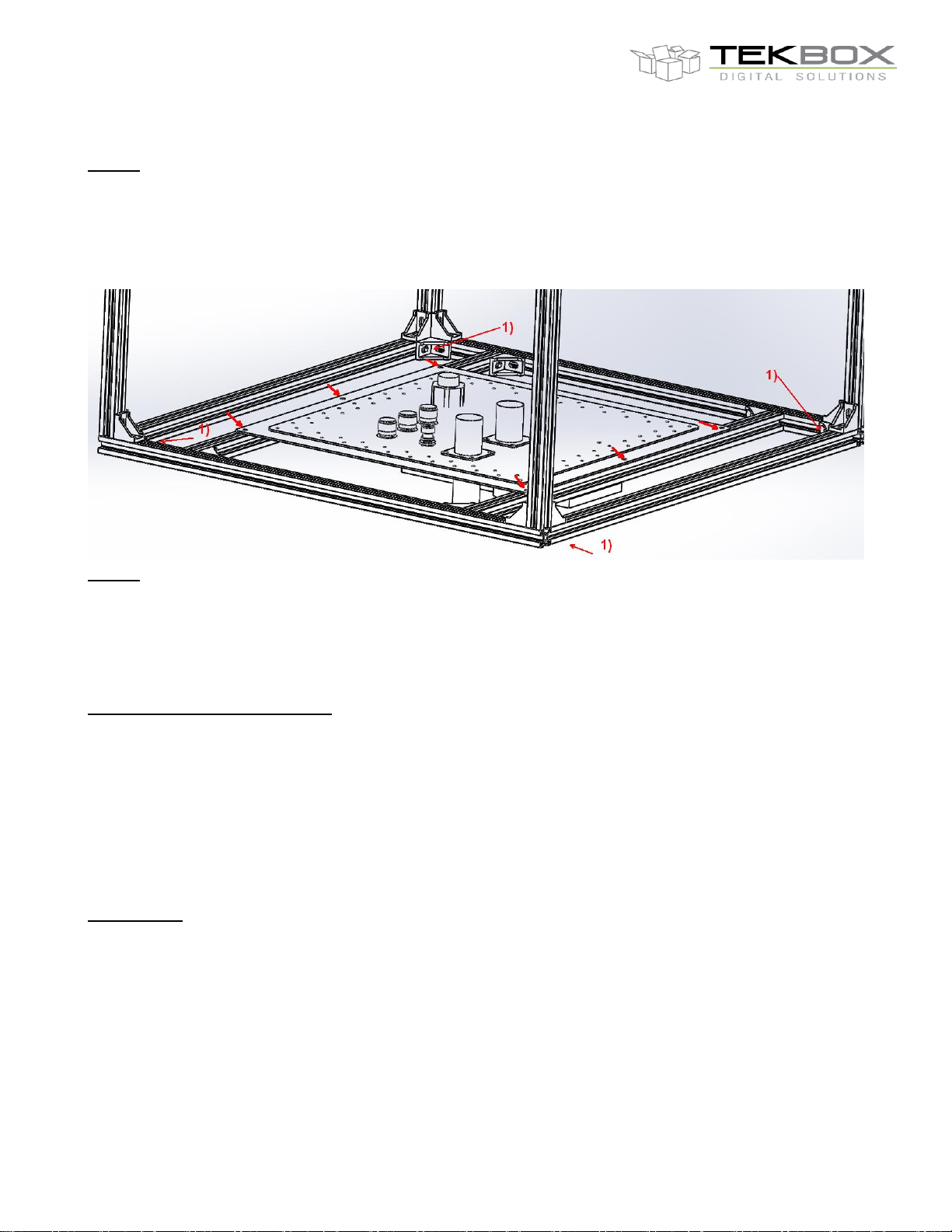
Unpack the fabrics and remove the outer foam protection of the filter plate.
Place the frame with the left side at the bottom and support the four corners to get clearance for the filters.
Attach the filter plate with six screws to the frame.
1) These edge elements are not used in case of the 80cm tent
Step 5:
Unfold the fabrics and fasten it to the frame with the attached Velcro strips.
5 Hints
Minimize residual ambient noise:
Ensure that there are no gaps between the conductive Velcro hook and loop tapes when closing the access
opening. Start closing it at the left or right upper corner and work your way through to the diagonally opposite
corner. Then start at the other upper corner and check if you can finalize without any big wave or gap. In case
that there is a gap, tear the tapes apart at the respective lower corner and re-attach it until it fits.
Use a RG223 or better cable to connect the spectrum analyzer to the outer connector of the tent. Avoid using
RG58 cables, as it may pick up additional ambient noise.
DUT control:
If your DUT requires connectivity to outside control devices or additional multiple voltages, use shielded control
cables and feed it through any unused filter or coaxial connector at the filter panel of the shielded tent. You can
also use the AC-filter to feed DC supply voltages into the tent. Similarly, the DC filters are capable of carrying
AC. Should you need multiple control cables or a USB or HDMI interface, you can feed it sideways through the
Velcro tape: use shielded cables and remove a section of the outer jacket to expose the shielding mesh of the
respective cable where it would pass the Velcro tape. Then close the tape tightly, ensuring that the cable shield
gets has good electrical contact with the tape. Ensure good ground of the set up and avoid connecting mains
phase to GND of the filter panel or surface of the tent.
Page 8
V1.4
8
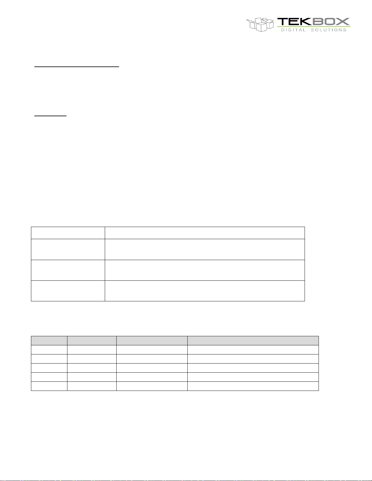
Part Number
Description
TBST-120/60/60/2
Shielded tent 120 cm x 60 cm x 60 cm, RF cable RG223/Nmale to N-male/1m, repair patch fabrics
TBST-86/49/45/1
Shielded tent 86 cm x 49 cm x 45 cm, RF cable RG223/Nmale to N-male/1m, repair patch fabrics, without mains filter
TBST-86/49/45/2
Shielded tent 86 cm x 49 cm x 45 cm, RF cable RG223/Nmale to N-male/1m, repair patch fabrics
Version
Date
Author
Changes
V 1.0
17.12.2017
Mayerhofer
Creation of the document
V 1.1
22.02.2018
Mayerhofer
All chapters updated
V 1.2
09.01.2019
Mayerhofer
All chapters updated
V 1.3
15.05.2019
Mayerhofer
Updated chapter 4, step 1
V 1.4
23.05.2019
Mayerhofer
Updated chapter 6
TBST-120/60/60/2; -86/49/45/1; -86/49/45/2
Shielded Tents
Internal AC mains connector:
The output of the AC filter is connected to a pigtail with detachable (non over molded) female Schuko connector.
Use a travel adapter or similar, to match it with any other country specific connector. Alternatively detach the
Schuko connector from the pigtail cable and mount a connector that fits your specific requirements.
Protection:
The main body of the tent is made of two layers of conductive fabrics, which may be damaged by sharp tools or
sharp edges of equipment. Handle with care.
For additional protection, insert a cardboard, foam or other suitable material at the bottom.
You may also attach MDF or plywood panels to the aluminum frame to protect the bottom or/and to stack
equipment on top of the tent.
In case of cuts, patch it with the supplied fabrics remnant. You can stitch it with any thread, provided that
stitching establishes a tight contact with the overlapping fabric.
6 Ordering Information
7 History
 Loading...