

Page 1

V1.18
Datasheet TBS12B/TBS12S
LoRaWAN RTU for SDI-12 sensors
© 2021 Tekbox Digital Solutions
Factory 4, F5, Lot I-3B-1 | Saigon Hi-Tech Park | Tan Phu Ward, District 9 | Ho Chi Minh City | Tel +84 (83)5471340
E-mail office@tekbox.net| www.tekbox.net
The TBS12B/TBS12S SDI-12 to LoRaWAN RTU bring LoRa wireless connectivity to SDI-12
compliant sensors to achieve long range communication. These RTU embed a low power
LoRaWAN certified modem, with dual antennas connectors to operate on low
(434MHz/470MHz) and high (868MHz/915MHz) ISM bands. They also integrate a fully SDI12 compatible data logger, that sends configurable SDI-12 commands to the sensors and
transmits the measurements over LoRa. TBS12B and TBS12S share the same features but
differ at power supply side: integrated solar panel and rechargeable battery (TBS12S) or
batteries powered only (TBS12B). They offer low current consumption, small footprint and
easy integration with SDI-12 sensors.
The TBS12B/TBS12S have been engineered specifically for applications where cost,
performance, range, time to market and ease of integration are prime considerations.
Features
▪ LoRaWAN 1.02 Class A – ABP/OTAA
▪ SDI-12 Standard V1.3
▪ Selectable frequency schemes:
EU, US, AU, AS, CN, Custom
▪ Easy configuration with PC tool through
TBS12’s UART port
▪ Low quiescent current
▪ TBS12S: integrated solar panel with
3.6V rechargeable battery
▪ TBS12B: 3*D cells batteries powered
▪ More than 15km range with clear line of
sight
▪ Configurable measurements and
transmission intervals.
▪ Operating Temperature Range:
-40°C - +85°C
Target Applications
▪ Any usual agricultural application (eg
crop yield optimization, precision
irrigation, etc…) where deploying SDI12 cables is an issue.
▪ Acts as a range extender for SDI-12 (up
to 15km instead of 60m)
▪ SDI-12 sensors network capacity
increase (thousands of nodes can be
deployed with only one gateway).
A
Page 2

V1.18
Datasheet TBS12B/TBS12S
LoRaWAN RTU for SDI-12 sensors
© 2021 Tekbox Digital Solutions
Factory 4, F5, Lot I-3B-1 | Saigon Hi-Tech Park | Tan Phu Ward, District 9 | Ho Chi Minh City | Tel +84 (83)5471340
E-mail office@tekbox.com| www.tekbox.com
2
Contents
1 PLATFORM OVERVIEW 3
1.1 MODULE OVERVIEW 3
1.2 VARIANTS OVERVIEW 4
1.2.1 TBS12B variant 4
1.2.2 TBS12S variant 4
2 SYSTEM OVERVIEW 5
2.1 HW SPECIFICATION 5
2.1.1 Platform characteristics 6
2.1.2 Sensors support 7
2.1.3 LoRaWAN modem 7
2.1.4 Power supply 7
3 PLATFORM CONNECTIVITY 8
3.1 TBS12S CONNECTIVITY 8
3.2 TBS12B CONNECTIVITY 10
3.3 SDI-12 CONNECTOR 10
4 FUNCTIONAL DESCRIPTION 11
4.1 INTERFACE FUNCTION 11
4.1.1 SDI-12 11
4.1.2 LoRa modem and radio 11
4.2 SYSTEM 12
4.2.1 Time intervals 13
4.2.2 Communication outage 14
4.2.3 Data format 14
5 TBS12B/TBS12S CONFIGURATION 17
6 POWER MANAGEMENT STRATEGY 17
7 TECHNICAL REFERENCES 18
7.1 SDI-12 18
7.2 LORAWAN 18
8 MECHANICAL SPECIFICATIONS 20
9 SDI-12 BASICS 20
10 LORAWAN NETWORK BASICS 21
10.1 OVERVIEW 21
10.2 INTEGRATING TBS12B/TBS12S IN A LORAWAN ECOSYSTEM 23
10.3 DEPLOYING TBS12B/TBS12S ON THE FIELD 24
11 ENVIRONMENTAL SPECIFICATIONS 24
12 ESD SAFETY 24
13 ROHS COMPLIANCE 24
14 ORDERING INFORMATION 25
15 HISTORY 25
Page 3

V1.18
Datasheet TBS12B/TBS12S
LoRaWAN RTU for SDI-12 sensors
© 2021 Tekbox Digital Solutions
Factory 4, F5, Lot I-3B-1 | Saigon Hi-Tech Park | Tan Phu Ward, District 9 | Ho Chi Minh City | Tel +84 (83)5471340
E-mail office@tekbox.com| www.tekbox.com
3
1 Platform overview
1.1 Module overview
The TBS12B/TBS12S RTU implement three main components:
• A SDI-12 controller, used to control SDI-12 sensors and send back measurements to internal host
• A LoRaWAN modem, used to transmit the SDI-12 measurements to the remote application server over
LoRa.
• An application host, that controls:
o SDI-12 commands configuration
o SDI-12 measurements
o LoRaWAN transmission
o Measurement and transmission intervals
o Measurements storage
o Power management
TBS12B/TBS12S functional block diagram
SDI-12 Controller
Application Host
LoRaWAN Modem
& Radio
ANTENNA
SDI-12
SENSORS
Page 4
V1.18
Datasheet TBS12B/TBS12S
LoRaWAN RTU for SDI-12 sensors
© 2021 Tekbox Digital Solutions
Factory 4, F5, Lot I-3B-1 | Saigon Hi-Tech Park | Tan Phu Ward, District 9 | Ho Chi Minh City | Tel +84 (83)5471340
E-mail office@tekbox.com| www.tekbox.com
4
1.2 Variants overview
The RTU based on that design exists in 2 variants depending on the power supply:
• TBS12B
o LoRaWAN RTU for SDI-12 sensors, powered by batteries
• TBS12S
o LoRaWAN RTU for SDI-12 sensors powered by rechargeable battery and solar panel
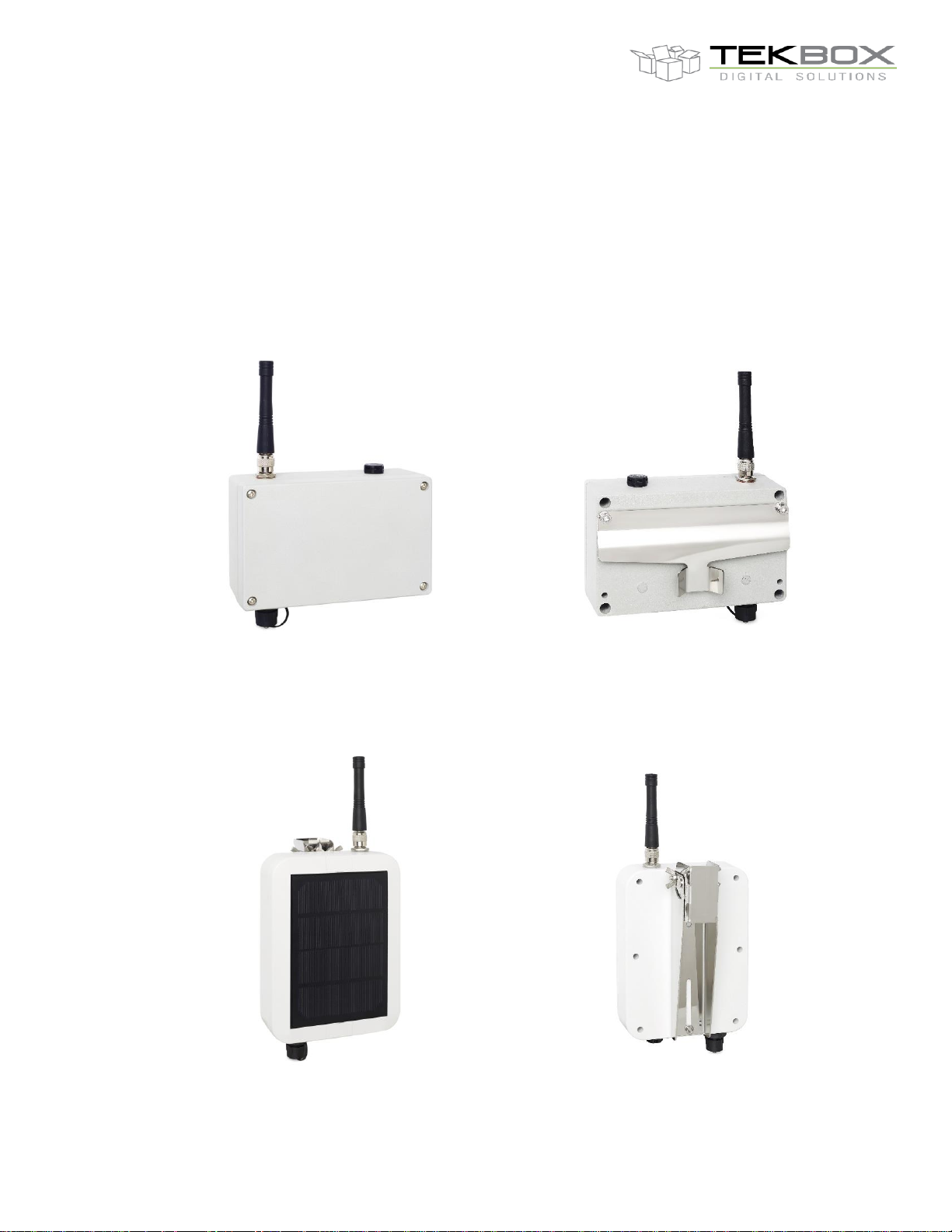
1.2.1 TBS12B variant
TBS12B: front view and rear view with fixture
1.2.2 TBS12S variant
TBS12S front view and rear view with fixture
Page 5
V1.18
Datasheet TBS12B/TBS12S
LoRaWAN RTU for SDI-12 sensors
© 2021 Tekbox Digital Solutions
Factory 4, F5, Lot I-3B-1 | Saigon Hi-Tech Park | Tan Phu Ward, District 9 | Ho Chi Minh City | Tel +84 (83)5471340
E-mail office@tekbox.com| www.tekbox.com
5
2 System overview
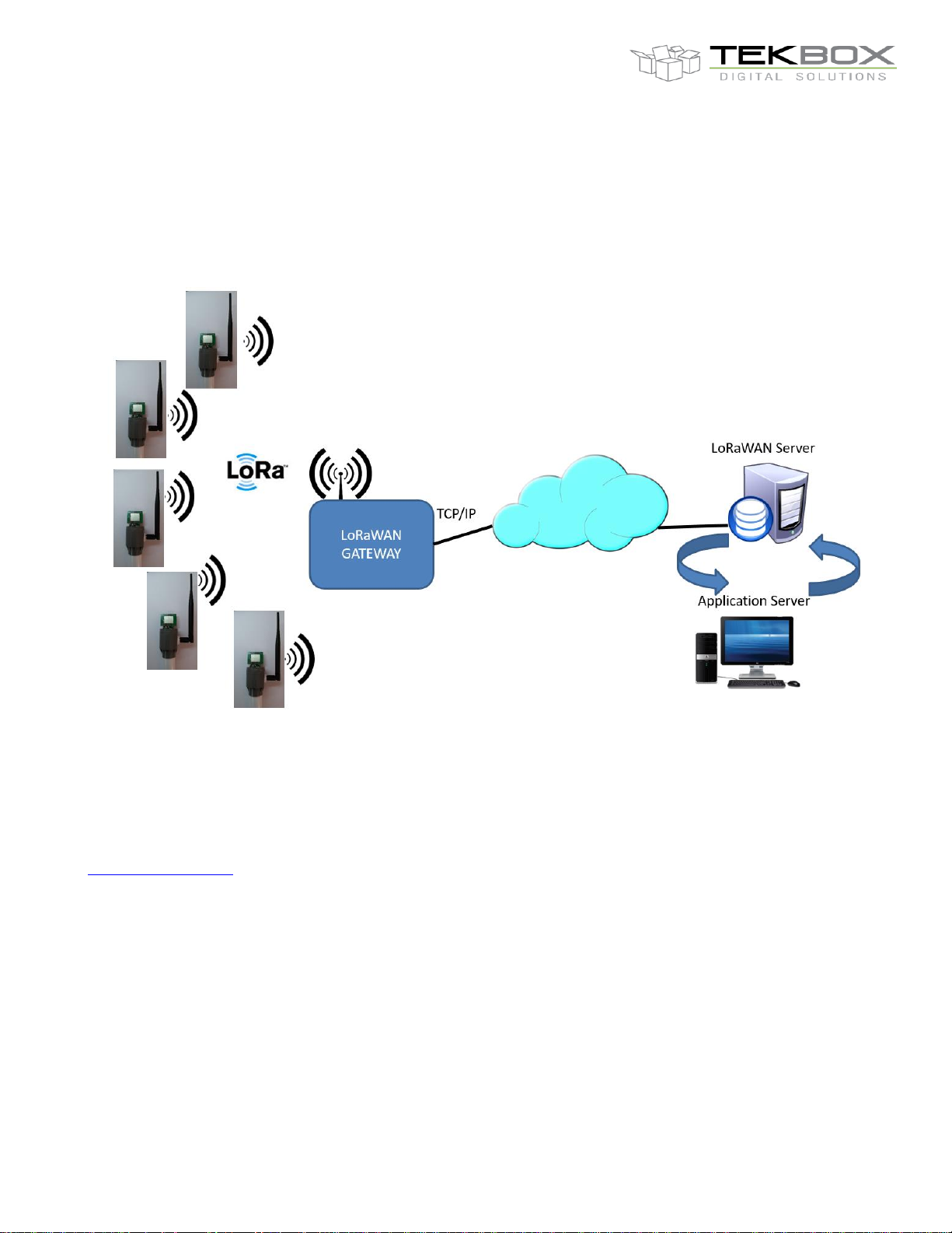
TBS12B/TBS12S integrate within a typical LoRaWAN ecosystem: each TBS12B/TBS12S LoRaWAN RTU is seen
as a unique end node within a LoRaWAN private network (ie including at least one LoRaWAN gateway and a
LoRaWAN server).
Deployment of a private LoRaWAN network
Before being used, TBS12B/TBS12S must go through a configuration and provisioning phase to initialize system,
SDI-12 and LoRaWAN parameters.
Device configuration is achieved by connecting TBS12B/TBS12S to a PC and running the configuration tool
provided along with this product. Further details pertaining to TBS12B/TBS12S configuration are found in
configuration chapter.
2.1 HW specification
The TBS12B/TBS12S are based on a low power controller and LoRaWAN modem, and a robust SDI-12 interface
hardware.
Page 6
V1.18
Datasheet TBS12B/TBS12S
LoRaWAN RTU for SDI-12 sensors
© 2021 Tekbox Digital Solutions
Factory 4, F5, Lot I-3B-1 | Saigon Hi-Tech Park | Tan Phu Ward, District 9 | Ho Chi Minh City | Tel +84 (83)5471340
E-mail office@tekbox.com| www.tekbox.com
6
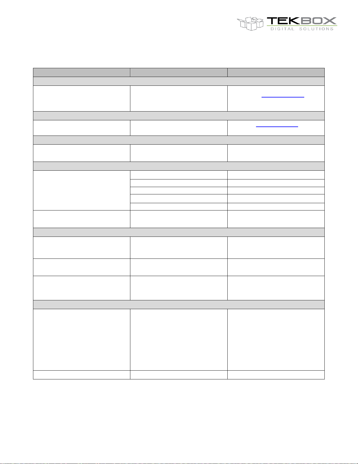
2.1.1 Platform characteristics
Feature
Description
Additional information
Sensors
SDI-12
V1.3
Refer to Sensors support for
further information.
Modem
Modem
LoRaWAN
Refer to wireless modem section
for further information.
Platform
Platform reset
Internally: reset button
Externally: reed switch
Not accessible for outdoor use
Hover a magnet over reed switch
Power supply (**)
Power supply
TBS12S
Outdoor use only
Solar panel
Integrated to the unit
Rechargeable battery
Not provided
TBS12B
Indoor/Outdoor use
Non rechargeable batteries
Not provided
Current in idle mode
TBS12B: 5-7 µA
TBS12S: 35 µA
Connectors
Connectors
3 pins (UART (RX, TX, GND)
internal connector
Used for TBS12B/TBS12S
configuration (requires TBS12 PC
configuration tool)
1 * 7 pins external connector
LLT-M14BMF07
For SDI-12 sensors connection
Antenna
Suitable for LoRaWAN
communication
Provided (868 – 915 MHz)
For 433/470MHz contact
sales@tekbox.com
Mechanical details
Housing
TBS12B:
IP67 aluminium housing: SP-AG-FA3-1
family, single piece gasket, IP67, TNC
antenna connector, Gore-Tex vent, IP67
circular panel connector
TBS12S:
Takachi enclosure, IP67 UV-Protect ASA
plastic box
Suitable for outdoor use.
Operating temperature range
-40 to +85°C
Page 7
V1.18
Datasheet TBS12B/TBS12S
LoRaWAN RTU for SDI-12 sensors
© 2021 Tekbox Digital Solutions
Factory 4, F5, Lot I-3B-1 | Saigon Hi-Tech Park | Tan Phu Ward, District 9 | Ho Chi Minh City | Tel +84 (83)5471340
E-mail office@tekbox.com| www.tekbox.com
7
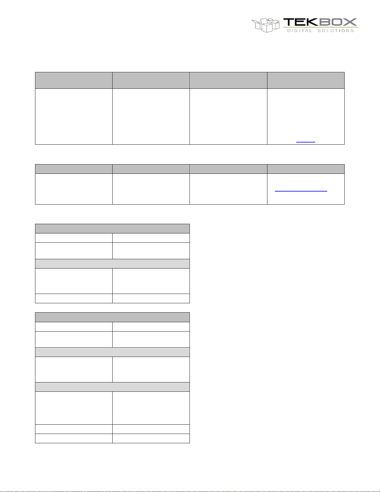
2.1.2 Sensors support
Sensor
Support
Electrical
characteristics
Additional information
SDI-12
Yes
1 port available
12V, 1200 baud SDI-12
data interface with
transient protection
SDI-12 v1.3 compliant
Limitation: aRx! not
supported
More sensors can be
connected by using a
SDI-12 junction box
(TBS04)
2.1.3 LoRaWAN modem
Modem
Frequencies
Protocol
Additional information
LoRa
EU868 US915
US915HYBRID CN779
EU433 AU915 CN470
AS923 KR920 IN865
LoRaWAN 1.02B
Class A
Contact
sales@tekbox.com for
433 MHz band support.
2.1.4 Power supply
TBS12B
Use
Indoor / Outdoor
Maximum delivered
current
3.2 A
Non rechargeable battery
Type
3 * 1.5V D cells
(ex. Duracell Ultra
Alkaline D battery)
Included
No
TBS12S
Use
Outdoor
Maximum delivered
current
3.2 A
Solar panel
Included
Yes
(integrated to the
housing)
Rechargeable battery
Type
3.7V LiIon
Size must fit the battery
holder 0.72” Dia * 2.56’’
H (18.2mm * 65.0mm)
Capacity
2000-3000 mAh
Included
No
Page 8
V1.18
Datasheet TBS12B/TBS12S
LoRaWAN RTU for SDI-12 sensors
© 2021 Tekbox Digital Solutions
Factory 4, F5, Lot I-3B-1 | Saigon Hi-Tech Park | Tan Phu Ward, District 9 | Ho Chi Minh City | Tel +84 (83)5471340
E-mail office@tekbox.com| www.tekbox.com
8
3 Platform connectivity
TBS12B/TBS12S provide following connectivity:
• 1 UART to control SDI-12 sensor
• 1 UART port for PC connection
• 1 SWIM port for FW update and connection to an emulator
• 1 slot for battery (form factor is variant dependant)
• 1 port for solar panel (TBS12S only – embedded on the housing)
• 2 internal antenna connectors (low and high LoRaWAN frequencies) linked to external antenna.
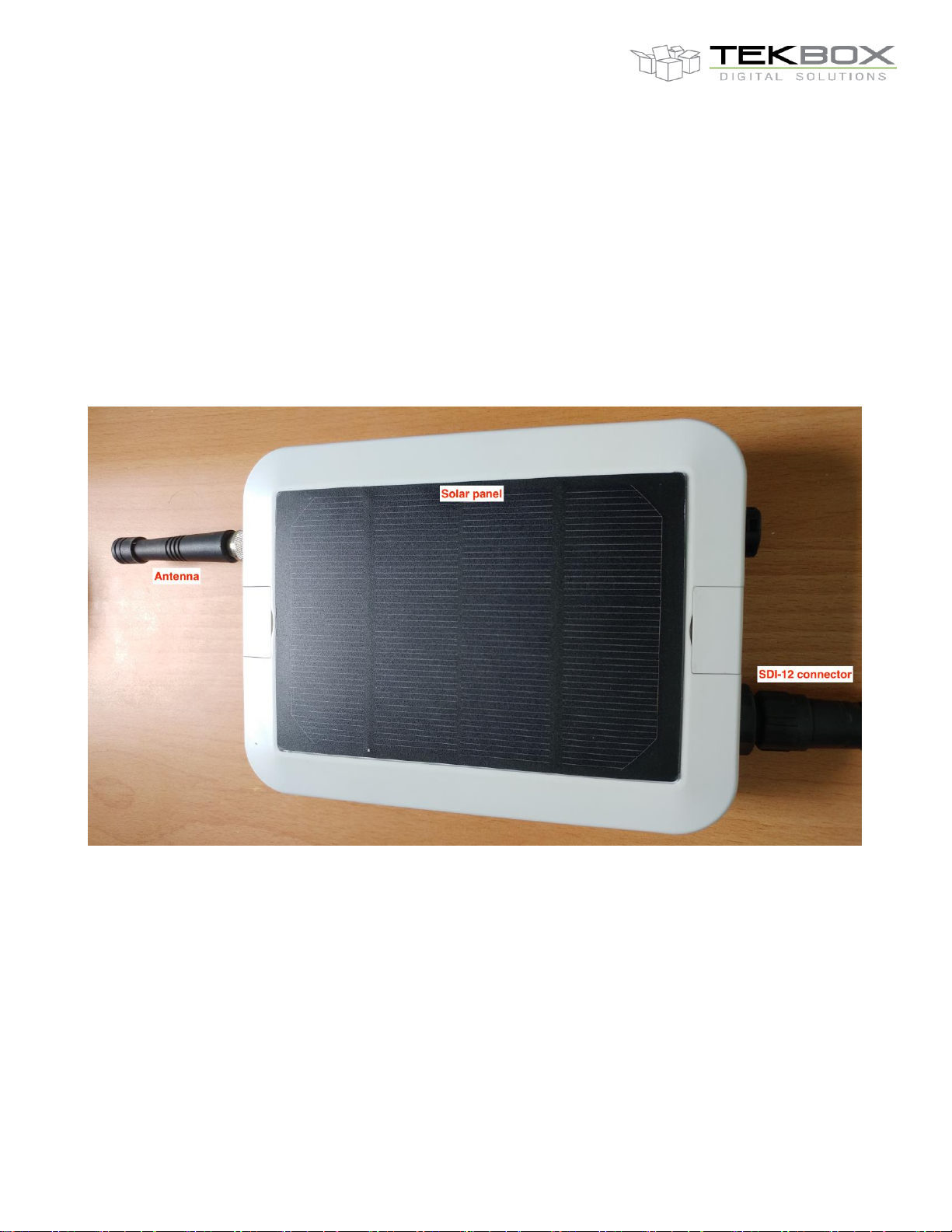
3.1 TBS12S connectivity
TBS12S – Housing closed
Page 9

V1.18
Datasheet TBS12B/TBS12S
LoRaWAN RTU for SDI-12 sensors
© 2021 Tekbox Digital Solutions
Factory 4, F5, Lot I-3B-1 | Saigon Hi-Tech Park | Tan Phu Ward, District 9 | Ho Chi Minh City | Tel +84 (83)5471340
E-mail office@tekbox.com| www.tekbox.com
9
TBS12S – Lid open
Page 10

V1.18
Datasheet TBS12B/TBS12S
LoRaWAN RTU for SDI-12 sensors
© 2021 Tekbox Digital Solutions
Factory 4, F5, Lot I-3B-1 | Saigon Hi-Tech Park | Tan Phu Ward, District 9 | Ho Chi Minh City | Tel +84 (83)5471340
E-mail office@tekbox.com| www.tekbox.com
10
3.2 TBS12B connectivity
3.3 SDI-12 connector
Both TBS12B and TBS1S have an external 7 pins connector to connect SDI-12 sensor:
Page 11

V1.18
Datasheet TBS12B/TBS12S
LoRaWAN RTU for SDI-12 sensors
© 2021 Tekbox Digital Solutions
Factory 4, F5, Lot I-3B-1 | Saigon Hi-Tech Park | Tan Phu Ward, District 9 | Ho Chi Minh City | Tel +84 (83)5471340
E-mail office@tekbox.com| www.tekbox.com
11
Pin
Description
GND (Pin 2)
Ground
To SDI-12 sensor GND
SDI-12 Data (Pin 5)
SDI-12 data line
To SDI-12 sensor data line
SDI-12 Power (Pin 6)
SDI-12 power
To SDI-12 sensor power line
Shield (Pin 7)
Cable’s shield (optional)
To be connected to SDI-12 sensor cable shield if any
4 Functional Description
4.1 Interface function
4.1.1 SDI-12
The SDI-12 standard defines a set of commands to configure sensors and to initiate measurements. Upon
receiving specific commands, the sensor may carry out internal tasks, respond with information on conversion
time or send measurement data.
SDI-12 commands are typically ASCII strings generated by the data recorder/controller firmware. The
TBS12B/TBS12S are connected to the TX output of the data recorder controller UART and converts the command
strings to the logic levels and baud rate specified by the SDI-12 standard. Furthermore, TBS12B/TBS12S module
handles breaks, marks and all other details of the SDI-12 protocol.
o Note: aRx! Commands are not supported by TBS12B and TBS12S.
Upon receiving data or status information originated by a Sensor, TBS12B/TBS12S extract the corresponding
ASCII strings and presents it to the RX input of the data recorder controller UART.
4.1.2 LoRa modem and radio
TBS12B/TBS12S embed a LoRaWAN compatible modem and a dual band LoRa radio.
Depending on the frequency plan that is used (country specific), either low or high ISM band will be needed. It is
therefore crucial to connect the antenna to the right connector:
Page 12

V1.18
Datasheet TBS12B/TBS12S
LoRaWAN RTU for SDI-12 sensors
© 2021 Tekbox Digital Solutions
Factory 4, F5, Lot I-3B-1 | Saigon Hi-Tech Park | Tan Phu Ward, District 9 | Ho Chi Minh City | Tel +84 (83)5471340
E-mail office@tekbox.com| www.tekbox.com
12
As LoRaWAN uses free ISM bands, useable frequencies are subject to local regulation, and TBS12B/TBS12S
must be configured accordingly:
- To use supported LoRaWAN frequency plans for countries where this has been defined
- To use custom plans for other countries
Refer to latest LoRaWAN specification on www.lora-alliance.org
TBS12B/TBS12S must be then used along with a LoRaWAN gateway that operates on the same frequency band:
for example, if they are deployed in Europe, both RTU and gateway must be configured to use EU868 frequency
plan.
The following LoRAWAN parameters are fully configurable:
• Device activation: ABP / OTAA
• Frequency plans: EU868 US915 US915HYBRID CN779 EU433 AU915 CN470 AS923 KR920 IN865;
configurable frequencies and data rates.
• Uplink communication – selectable confirmed or unconfirmed messages, repeat feature
• Downlink communication: not supported.
• Reconfigurable LoRaWAN parameters: identifiers (DevAddr, DevEUI) and security keys (NwkSKey,
AppSKey, AppKey)
Both TBS12B and TBS12S have a UART port used to connect to a PC that runs the configuration tool. For further
information about the configuration process refer to the documentation embedded within the PC configuration tool
delivered by Tekbox.
4.2 System
TBS12B/TBS12S act as a RTU: they are designed to trigger SDI-12 measurements on a regular basis, and
transmit the measurements over LoRa to application server on defined time interval.
SDI-12 measurements are stored inside the RTU internal memory until they’re transmitted.
All of these parameters are configurable:
• Fully configurable set of SDI-12 commands to be executed (up to 40 Measurement/Data commands pairs)
• Programmable measurement and transmission intervals (from 1 minute to 24 hours)
• Configurable battery information reporting interval
• Configurable transmission delay: allow to stagger the transmission of multiple TBS12B/TBS12S units
deployed in the same vicinity, contributing then to reduce the collision rate.
• 2 modes of operation while connected to TBS12 PC application:
o Logging mode: TBS12B/TBS12S operates normally but outputs debug information to the PC tool
o Console mode: TBS12B/TBS12S is in configuration mode, its system, SDI-12 and LoRaWAN
parameters can be checked and updated. Moreover, it is possible to directly access connected
SDI-12 sensors and LoRaWAN modem by sending any supported SDI-12 commands/LoRaWAN
modem AT command (this is an advanced diagnosis feature).
Page 13

V1.18
Datasheet TBS12B/TBS12S
LoRaWAN RTU for SDI-12 sensors
© 2021 Tekbox Digital Solutions
Factory 4, F5, Lot I-3B-1 | Saigon Hi-Tech Park | Tan Phu Ward, District 9 | Ho Chi Minh City | Tel +84 (83)5471340
E-mail office@tekbox.com| www.tekbox.com
13
4.2.1 Time intervals
Three different time intervals are defined in the system:
- Measurement interval
o Period in minutes to perform SDI-12 measurements and store data into internal memory.
- Transmission interval
o Period in minutes to transmit measurements stored in the RTU internal memory over LoRa
- Monitoring interval
o Period in minutes to transmit monitoring information (eg battery level) over LoRa to the application
server. This must be a multiple of the Transmission Interval.
These parameters are configured with the TBS12 Configuration Tool.
Intervals are set in minutes from 1min to 1440 minutes (ie 24 hours).
A transmission delay can be set in case multiple RTU are deployed in the same area. Having several RTU sending
data at the same time will result in numerous packets collisions, therefore staggering the transmission of each
units over the transmission interval will help reducing this effect.
The staggering delay should be carefully chosen so there’s no overlap with the next transmission interval.
Following sequence shows 6 TBS12B/TBS12S units transmitting their data on a 30s slot basis spread over a 6
minutes transmission interval:
Below diagram shows how TBS12B/TBS12S operate with a 1 hour measurement interval and 3 hours transmission
interval:
Page 14

V1.18
Datasheet TBS12B/TBS12S
LoRaWAN RTU for SDI-12 sensors
© 2021 Tekbox Digital Solutions
Factory 4, F5, Lot I-3B-1 | Saigon Hi-Tech Park | Tan Phu Ward, District 9 | Ho Chi Minh City | Tel +84 (83)5471340
E-mail office@tekbox.com| www.tekbox.com
14
Note: it is strongly recommended to use same interval for both measurements and transmission (e.g. each
15 minutes) to ensure smooth operation of the RTU.
4.2.2 Communication outage
Communication outage situations can be mitigated by using LoRaWAN confirmed messages and setting the retry
counter accordingly to minize the risk of not getting the ACK from the LoRaWAN server.
4.2.3 Data format
Each measurement stored in internal memory is time stamped, and one packet of data corresponds to one sensor.
As an example, if 5 SDI-12 sensors are connected to TBS12B/TBS12S, 5 packets of data are stored in memory
upon each measurement interval.
Page 15

V1.18
Datasheet TBS12B/TBS12S
LoRaWAN RTU for SDI-12 sensors
© 2021 Tekbox Digital Solutions
Factory 4, F5, Lot I-3B-1 | Saigon Hi-Tech Park | Tan Phu Ward, District 9 | Ho Chi Minh City | Tel +84 (83)5471340
E-mail office@tekbox.com| www.tekbox.com
15
TBS12B/TBS12S transmits 4 types of messages:
- Measurement message
- Battery reporting message
- Common reporting message
- LinkCheckReq
Measurement message
This message is a string formatted as follows:
PSYY:MM:DD:HH:MM:00<Sensor_ID><SubSensor_ID><Nb_values> Value1 Value2 … ValueN
Where:
• <PS>: packet header for SDI-12 parameters
• <YY:MM:DD> is the date with <YY> being the last 2 digits of the year, <MM> the month number and <DD>
the date. For example, <18:06:01> is the 1rst of June 2018.
• <HH:MM:00> is the time represented as hours/minutes/seconds, eg 16:25:00.
o Note: time is 24h format (ie no AM/PM representation)
o Number of seconds is always 00 (time alignment with round hour).
• <Sensor_ID>: virtual ID corresponding to a physical sensor that has its own specific SDI-12 address.
• <SubSensor_ID>: index of the SDI-12 commands that is executed for a specific Sensor_ID.
• <Nb_values>: number of measurements returned by the SDI-12 sensor, coded over 2 bytes.
• Space character: separator
• <Value1>… <ValueN>: SDI-12 measurements formatted as per SDI-12 standard (pd.d).
Example:
A TBS12S has 4 SDI-12 sensors attached, the following tables shows the programmed SDI-12 commands and
the Sensor_ID/SubSensor_ID allocation (automatically handled by the platform):
SDI-12 command index
SDI-12 command
Sensor_ID
SubSensorID
0
0M! 0 0
1
0C! 0 1
2
1M! 1 0 3 1C1! 1 1 4 3M1! 2 0 5 eM! 3 0 6 eM1! 3 1 7 eC! 3 2
PS18:06:01:16:25:003202 +37.37 +29.65
- Time stamp: 1rst of June 2018 (date) 16:15:00 (time)
- ‘3’: Sensor_ID is 3
- ‘2’: SubSensor_ID is 2
- ‘02’: 2 SDI-12 measurements returned by the sensor
- SDI-12 measurements: +37.37 and +29.65
Page 16

V1.18
Datasheet TBS12B/TBS12S
LoRaWAN RTU for SDI-12 sensors
© 2021 Tekbox Digital Solutions
Factory 4, F5, Lot I-3B-1 | Saigon Hi-Tech Park | Tan Phu Ward, District 9 | Ho Chi Minh City | Tel +84 (83)5471340
E-mail office@tekbox.com| www.tekbox.com
16
Battery measurement message
This message is a string formatted as follows:
PBYY:MM:DD:HH:MM:00 <Battery_voltage>Where:
• <PB>: packet header for battery voltage parameter
• <YY:MM:DD> is the date with <YY> being the last 2 digits of the year, <MM> the month number and <DD>
the date. For example, <18:06:01> is the 1rst of June 2018.
• <HH:MM:00> is the time represented as hours/minutes/seconds, eg 16:25:00.
o Note: time is 24h format (ie no AM/PM representation)
• Space character: separator.
• <Battery_voltage>: battery voltage in V coded over 5 digit including the decimal separator.
Example:
PB18:06:01:17:00:00 3.600
- Time stamp: 1rst of June 2018 (date) 17:00:00 (time)
- Battery voltage: 3.6V
Common reporting message
This message is a string formatted as follows:
CYY:MM:DD:HH:MM:SS<BoardID><FW><PowerID><SensorsNb><Status> <RSSI> Where:
• <C>: packet header for common reporting message
• <YY:MM:DD> is the date with <YY> being the last 2 digits of the year, <MM> the month number and <DD>
the date. For example, <20:08:19> is the 19th of August 2020
• <HH:MM:SS> is the time represented as hours/minutes/seconds, eg 16:25:00.
o Note: time is 24h format (ie no AM/PM representation)
• <BoardID>: board ID coded over 8 characters
• <FW>: FW version coded over 8 characters
• <PowerID>: power supply identifier, set to 0 (reserved for future use)
• <SensorsNb>: number of connected sensors
• <Status>: TBS12x status, ‘S’: startup, ‘R’: running
• Space character: separator
• <RSSI>: signed RSSI value
Example:
C20:08:18:22:12:00000001010200010705R -105
C: common reporting message
Date: 18th of August 2020
Time: 22:12:00 (10:12PM)
BoardID: 00000101
FW version: 02.00.01.07
PowerID: 0
Number of connected sensors: 5
TBS12S status: Running (‘R’)
Page 17

V1.18
Datasheet TBS12B/TBS12S
LoRaWAN RTU for SDI-12 sensors
© 2021 Tekbox Digital Solutions
Factory 4, F5, Lot I-3B-1 | Saigon Hi-Tech Park | Tan Phu Ward, District 9 | Ho Chi Minh City | Tel +84 (83)5471340
E-mail office@tekbox.com| www.tekbox.com
17
RSSI: -105 dB
LinkCheckReq
This message doesn’t hold any payload as this is a LoRaWAN MAC layer command.
It is used by the platform to measure the RSSI and check the connectivity with the LoRaWAN gateway.
5 TBS12B/TBS12S configuration
Before being used, TBS12B/TBS12S must be configured:
- With ad hoc LoRaWAN ID and ciphering keys to operate on the selected LoRaWAN service provider.
- With LoRa frequencies and data rates corresponding to the area where the RTU is deployed (subject to
loca regulation and as per LoRaWAN standard)
- With optional LoRaWAN parameters like ADR, confirmed/unconfirmed messages, …
- With measurement and transmission intervals
TBS12B/TBS12S configuration is achieved through a PC application that accesses the device through its external
UART port.
When the RTU is connected to PC application, its internal date and time are automatically updated.
TBS12B/TBS12S are designed so they can’t operate until its date and time have been set through the PC
application.
A maximum of 16 SDI-12 commands can be programmed.
Refer to the TBS12B/TBS12S PC configuration tool user guide for further information.
6 Power Management strategy
TBS12B/TBS12S integrate automatic power management feature. When the device neither measures nor
transmits, the MCU goes to deep sleep mode, SDI-12 HW stage is disabled and LoRaWAN modem is in ultra low
power mode.
Following screenshot mirrors the current consumption in a typical TBS12B/TBS12S operating sequence, where
measurement and transmission intervals occur at the same time: the platform wakes up from sleep mode, then
performs SDI-12 measurements, and finally transmit all measurements stored since last transmission over LoRa.
Page 18

V1.18
Datasheet TBS12B/TBS12S
LoRaWAN RTU for SDI-12 sensors
© 2021 Tekbox Digital Solutions
Factory 4, F5, Lot I-3B-1 | Saigon Hi-Tech Park | Tan Phu Ward, District 9 | Ho Chi Minh City | Tel +84 (83)5471340
E-mail office@tekbox.com| www.tekbox.com
18
7 Technical references
7.1 SDI-12
SDI-12 is a standard for interfacing data recorders with microprocessor-based sensors. SDI-12 stands for
serial/digital interface at 1200 baud. It can connect multiple sensors with a single data recorder on one cable. It
supports up to 60 meters of cable between a sensor and a data logger.
The SDI-12 standard is prepared by
SDI-12 Support Group
(Technical Committee)
165 East 500 South
River Heights, Utah
435-752-4200
435-752-1691 (FAX)
http://www.sdi-12.org
The latest standard is version V1.3 and dates from July 18th, 2005. The standard is available on the web site of
the SDI-12 Support Group. More information on SDI-12 is presented in chapter 6.
7.2 LoRaWAN
LoRaWAN is a MAC layer radio protocol for LoRa (technology owned by Semtech, www.semtech.com) developed
and maintained by LoRa Alliance:
Page 19

V1.18
Datasheet TBS12B/TBS12S
LoRaWAN RTU for SDI-12 sensors
© 2021 Tekbox Digital Solutions
Factory 4, F5, Lot I-3B-1 | Saigon Hi-Tech Park | Tan Phu Ward, District 9 | Ho Chi Minh City | Tel +84 (83)5471340
E-mail office@tekbox.com| www.tekbox.com
19
www.lora-alliance.org
LoRa™ Alliance
2400 Camino Ramon, #375
San Ramon, CA 94583
Phone: +1 925-275-6611
Fax: +1 925-275-6691
“LoRaWAN™ is a Low Power Wide Area Network (LPWAN) specification intended for wireless battery operated Things in a regional,
national or global network. LoRaWAN targets key requirements of Internet of Things such as secure bi-directional communication, mobility
and localization services. The LoRaWAN specification provides seamless interoperability among smart Things without the need of complex
local installations and gives back the freedom to the user, developer, businesses enabling the roll out of Internet of Things.”
Further details available on LoRa Alliance website (https://www.lora-alliance.org/What-Is-LoRa/Technology).
Page 20

V1.18
Datasheet TBS12B/TBS12S
LoRaWAN RTU for SDI-12 sensors
© 2021 Tekbox Digital Solutions
Factory 4, F5, Lot I-3B-1 | Saigon Hi-Tech Park | Tan Phu Ward, District 9 | Ho Chi Minh City | Tel +84 (83)5471340
E-mail office@tekbox.com| www.tekbox.com
20
8 Mechanical Specifications
TBS12B TBS12S
Product
Dimensions
Weight
TBS12B
100*160*60 mm
0.9 kg
TBS12S
130*175*45 mm
0.5 kg
9 SDI-12 Basics
SDI-12 is a serial data communication standard for interfacing multiple sensors with a data recorder The SDI-12
uses a shared bus with 3 wires: power (12V), data, ground
Data rate: 1200 baud
Each sensor at the bus gets a unique address which is in the range ASCII [0-9, a-z, A-Z]. The default address of
every sensor is ASCII[0]. When setting up a SDI-12 sensor network, every sensor needs to be configured with a
unique address. This can be done using the “Change Address Command”.
Page 21

V1.18
Datasheet TBS12B/TBS12S
LoRaWAN RTU for SDI-12 sensors
© 2021 Tekbox Digital Solutions
Factory 4, F5, Lot I-3B-1 | Saigon Hi-Tech Park | Tan Phu Ward, District 9 | Ho Chi Minh City | Tel +84 (83)5471340
E-mail office@tekbox.com| www.tekbox.com
21
A sensor typically can measure one or more parameters. Sensor manufacturers usually specify “Extended
Commands” to configure or calibrate sensors. These commands are specified by the manufacturer, but they follow
the command structure specified by SDI-12.
A typical recorder/sensor measurement sequence proceeds as follows:
1) The data recorder wakes all sensors on the SDI-12 bus with a break.
2) The recorder transmits a command to a specific, addressed sensor, instructing it to make a measurement.
3) The addressed sensor responds within 15.0 milliseconds returning the maximum time until the measurement
data will be ready and the number of data values it will return.
4) If the measurement is immediately available, the recorder transmits a command to the sensor instructing it to
return the measurement result(s). If the measurement is not ready, the data recorder waits for the sensor to send
a request to the recorder, which indicatesthat the data are ready. The recorder then transmits a command to get
the data.
5) The sensor responds, returning one or more measurement results.
SDI-12 command structure:
Each SDI-12 command is an ASCII string with up to 5 characters, starting with the sensor address and terminated
by a ! character.
Example:
Send Identification Command 0I!
0 is the sensor address (sensor zero). Upon receiving this command, the sensor will send an ASCII string
containing sensor address, a SDI-12 compatibility number, company name, sensor model number, sensor version
number and sensor serial number.
The standard process to carry out a measurement is to send a measurement request upon which the sensor
responds with the time that is required to carry out the measurement and the number of data items being returned.
After waiting the time that the sensor requires to carry out the measurement, the data recorder sends a “Read
Command” to get the measurement results.
Example:
Start Measurement Command 0M1!
Sensor 0 might respond 00302 which means the measurement will take 30 seconds and deliver 2 values.
After min. 30 seconds, the data recorder can send the Read Data Command 0D0! To which Sensor 0 might reply
0+27+1050. +27+1050 is the two measurement results which may be 27°C and 1050 milibar.
The response string of a sensor is always in ASCII format and may contain up to 40 or up to 80 characters,
depending on the type of command. Out of 40 or 80 characters, the values part of the response string may
contain up to 35 or 75 characters.
The response string of a sensor is always in ASCII format and may contain up to 40 or up to 80 characters,
depending on the type of command. Out of 40 or 80 characters, the values part of the response string may contain
up to 35 or 75 characters.
10 LoRaWAN network basics
10.1 Overview
This section provides TBS12B/TBS12S user a basic understanding of LoRaWAN key features, so they can be
integrated smoothly in such ecosystem.
LoRa Alliance describes a LoRaWAN network as follows:
Page 22

V1.18
Datasheet TBS12B/TBS12S
LoRaWAN RTU for SDI-12 sensors
© 2021 Tekbox Digital Solutions
Factory 4, F5, Lot I-3B-1 | Saigon Hi-Tech Park | Tan Phu Ward, District 9 | Ho Chi Minh City | Tel +84 (83)5471340
E-mail office@tekbox.com| www.tekbox.com
22
“
LoRaWAN network architecture is typically laid out in a star-of-stars topology in which gateways is a transparent bridge relaying
messages between end-devices and a central network server in the backend. Gateways are connected to the network server via standard
IP connections while end-devices use single-hop wireless communication to one or many gateways. All end-point communication is
generally bi-directional, but also supports operation such as multicast enabling software upgrade over the air or other mass distribution
messages to reduce the on air communication time.
Communication between end-devices and gateways is spread out on different frequency channels and data rates. The selection of the
data rate is a trade-off between communication range and message duration. Due to the spread spectrum technology, communications
with different data rates do not interfere with each other and create a set of “virtual” channels increasing the capacity of the gateway.
LoRaWAN data rates range from 0.3 kbps to 50 kbps. To maximize both battery life of the end-devices and overall network capacity, the
LoRaWAN network server is managing the data rate and RF output for each end-device individually by means of an adaptive data
rate (ADR) scheme.
“
This leads then to a network where each TBS12B/TBS12S is a unique end node communicating with a gateway
as highlighted in below schematics:
Several components are involved in the LoRaWAN network:
- End nodes: this is any end-user device integrating a LoRaWAN modem and communicating with a
LoRaWAN gateway. With respect to this, TBS12B/TBS12S are end nodes.
- Gateway: it acts as a packet forwarder between end nodes and LoRaWAN server. It communicates
through LoRa radio with end nodes, and through a TCP/IP connection with LoRaWAN server (depending
on the gateway capability, this can be achieved with an Ethernet, wifi or cellular connection). One gateway
Page 23

V1.18
Datasheet TBS12B/TBS12S
LoRaWAN RTU for SDI-12 sensors
© 2021 Tekbox Digital Solutions
Factory 4, F5, Lot I-3B-1 | Saigon Hi-Tech Park | Tan Phu Ward, District 9 | Ho Chi Minh City | Tel +84 (83)5471340
E-mail office@tekbox.com| www.tekbox.com
23
can accommodate thousands of end nodes, and typical range is 2km in urban areas and around 15km in
rural areas with clear line of sight.
- LoRaWAN server: this is a service provided by a 3rd party company (hence the user needs to subscribe
to such service). As LoRaWAN packets are encrypted, the LoRaWAN server proceeds with deciphering
of LoRaWAN packets and make them available to user’s application server through various
communication protocols (this is totally dependant on the LoRaWAN service provider, but HTTPS,
WebSocket and REST are widely used protocols besides direct integration with IoT platforms like
Microsoft Azure or AWS IoT). An API is then provided to access deciphered data, device EUI and other
radio parameters (usually in JSON or XML format).
10.2 Integrating TBS12B/TBS12S in a LoRaWAN ecosystem
To build a private network of TBS12B/TBS12S, it is first required to choose a LoRaWAN gateway (eg
www.kerlink.com, www.multitech.com, …) and a LoRaWAN services provider (eg www.loriot.io, …).
TBS12B/TBS12S are compatible with any LoRaWAN certified gateway and network service provider.
This choice is dependant on several criteria:
- Geographic area where the sensors will be deployed: this determines the LoRaWAN frequency plan to be
used. The gateway must then have required HW to support these frequencies (eg 868MHz, 915MHz,
etc…)
- Gateway connectivity: depending on where the gateway will be installed, next options need to be
considered,
o Indoor / outdoor model
o Connectivity: Ethernet, cellular, wifi
- The LoRaWAN service provider:
o Needs to support the chosen gateway (because it will be programmed to access the selected
LoRaWAN service provider)
o Must support the frequency plans required by the user
o Must support the LoRaWAN features required by the user (eg LoRaWAN downlink, Class C,
OTAA, etc…)
o Provides a suitable interface for the user so the application server can collect deciphered data (eg
JSON/XML API reachable through Websocket, REST, etc…)
o Must be ideally located in the same region where end nodes are deployed, to avoid latenties (eg
end nodes in Vietnam, LoRaWAN server in Singapore but not in Germany)
o Support of multiple applications/accounts, scalability of the server, …
o Pricing model: subscription based, billing per gateway and end nodes, etc…
The next step is to activate each end node so they are identified and can communicate with the LoRaWAN network.
LoRaWAN standard defines 2 ways of activating end nodes:
- Activation By Personalization (ABP): with this configuration, the end node is bound to a specific LoRaWAN
network. This mode is supported by default in TBS12B/TBS12S, and can be compared to a smartphone
that is SIM-locked to a specific cellular network.
Page 24

V1.18
Datasheet TBS12B/TBS12S
LoRaWAN RTU for SDI-12 sensors
© 2021 Tekbox Digital Solutions
Factory 4, F5, Lot I-3B-1 | Saigon Hi-Tech Park | Tan Phu Ward, District 9 | Ho Chi Minh City | Tel +84 (83)5471340
E-mail office@tekbox.com| www.tekbox.com
24
- Over the Air Activation (OTAA): this configuration is optional on TBS12. It gives the end node the “roaming”
capability, ie the end node is not bound to a specific network, and can be re-activated on different
LoRaWAN network through OTAA procedure.
Both activation modes require following identifiers & keys configuration:
Note: the generation of DevAddr in ABP mode is dependant on the LoRaWAN service provider. It can be any
random value generated by the user, or can be generated from EUI (or other mean) by the LoRaWAN service
provider.
Good practice is to define an EUI for an end node, whether it is activated by ABP or OTAA.
10.3 Deploying TBS12B/TBS12S on the field
It is key having the gateway installed as high as possible to get increased communication range.
11 Environmental Specifications
Symbol
Parameter
Conditions
Min
Max
Unit
TA
Operating Ambient
Temperature Range
-40
+85
°C
T
STG
Storage Temperature
Range
-40
+85
°C
Humidity level
Ta=60°C; no condensation
-
95
% R.H
Table 1 – Environmental Specifications
12 ESD Safety
TBS12B/TBS12S are static-sensitive electronic devices. Do not operate or store near strong electrostatic fields.
Follow guidelines as per EIA/JESD22-A115-A.
13 RoHS Compliance
TBS12B/TBS12S modules are compliant with the European Union Directive 2002/95/EC Restriction on the Use of
Hazardous Substances (RoHS). All designated products have Pb-free terminals.
Page 25

V1.18
Datasheet TBS12B/TBS12S
LoRaWAN RTU for SDI-12 sensors
© 2021 Tekbox Digital Solutions
Factory 4, F5, Lot I-3B-1 | Saigon Hi-Tech Park | Tan Phu Ward, District 9 | Ho Chi Minh City | Tel +84 (83)5471340
E-mail office@tekbox.com| www.tekbox.com
25
14 Ordering Information
Part Number
Description
TBS12B
LoRaWAN RTU for SDI-12 sensors
TBS12S
LoRaWAN RTU for SDI-12 sensors + integrated solar panel
TBSBR02
Mounting bracket for TBS12B
TBSBR03
Mounting bracket for TBS12S
Contact: sales@tekbox.com
15 History
Version
Date
Author
Changes
V1.0
02.11.2016
Philippe Hervieu
Creation of the document
V1.1
03.11.2016
Philippe Hervieu
Remove soldering profile and packaging chapters / Update
power management, Electrical specifications and
Mechanical Specification sections.
V1.2
06.02.2017
Philippe Hervieu
Battery information updated
V1.3
06.02.2017
Philippe Hervieu
Details about date and time programming in the unit
V1.4
03.08.2017
Philippe Hervieu
Update current consumption in sleep mode
V1.5
02.10.2017
Philippe Hervieu
Add Tekbox/Takachi variants descriptions
V1.6
10.04.2018
Philippe Hervieu
Update products names
V1.7
01.06.2018
Philippe Hervieu
Update power consumption section and messages format
V1.8
25.06.2018
Philippe Hervieu
Add TBS12S connectivity
V1.9
24.08.2018
Philippe Hervieu
Update TBS12 variants
V1.10
02.10.2018
Philippe Hervieu
Update configuration section.
V1.11
18.10.2018
Philippe Hervieu
Recommendation about using same measurement and
transmission intervals.
V1.12
19.11.2018
Philippe Hervieu
Update PS message format (size of returned parameters).
V1.13
19.08.2020
Philippe Hervieu
Add C message description
V1.14
03.09.2020
Philippe Hervieu
Update UART speed for PC-TBS12x communication
V1.15
04.09.2020
Philippe Hervieu
Fix typo in packets frame format / Add LinkCheckReq
description
V1.16
09.11.20
Philippe Hervieu
Update communication outage chapter
V1.17
27.11.20
Philippe Hervieu
Remove LoRaWAN head
V1.18
14.01.21
Philippe Hervieu
Rework HW description and remove LoRaWAN head.
 Loading...