

Page 1

V1.8
TBS09S Modbus Master to SDI 12 Slave Converter
TBS09S_ModbusMaster
Modbus Master to SDI 12 Slave Converter
The TBS09S is a converter to connect SDI-12 sensors to a Modbus master. It can control multiple
SDI12 sensors in parallel by individually addressing the connected SDI-12 sensors.
Features
Modbus Master to SDI 12 Slave Converter
Multiple SDI-12 sensors can be connected
SDI-12 Standard V1.3
Modbus RTU, 19200 baud
Switched sensor supply voltage output
5 - 16V supply voltage
6mA current consumption when active
© 2020 Tekbox Digital Solutions
Factory 4, F5, Lot I-3B-1, Saigon HiTech Park, Q.9 | Ho Chi Minh City | Tel +84 287 1099865| office@tekbox.com| www.tekbox.com
20µA in idle, 4mA in active mode
Operating Temperature Range:
- 40°C … + 80°C
Target Applications
SDI-12 sensor networks with Modbus
controller
Page 2

V1.8
2
TBS09S
Modbus Master to SDI-12 Slave Converter
Contents
1 INTRODUCTION 3
2 PRODUCT SPECIFICATION 3
3 CALIBRATION AND SETTINGS 4
4 CONNECTIONS 5
5 SENDING SDI-12 COMMANDS THROUGH TBS09S 6
5.1 SUPPORTED SDI-12 COMMANDS 6
5.2 MODBUS DEFAULT CONFIGURATION AND FRAMES FORMAT 7
5.2.1 Default configuration 7
5.2.2 Modbus master to TBS09S: Modbus request format 7
5.2.3 TBS09S to Modbus master: Modbus response format 7
5.3 TBS09S MODBUS REGISTERS MAPPING 8
5.4 TBS09S MODBUS REQUESTS DETAILED DESCRIPTION 10
5.4.1 Modbus slave address change 10
5.4.2 Query sensor’s SDI-12 address (SDI-12 command: ?!) 11
5.4.3 Change sensor’s SDI-12 address (SDI-12 command: aAb!) 12
5.4.4 SDI-12 Measurement (SDI-12 commands: aM!/aMC!/aMx!/aMCx!/aC!/aCC!/aCCx!)12
5.5 TBS09S / SDI-12 SENSOR COMMUNICATION FLOW EXAMPLE 15
6 SDI-12 16
7 HISTORY 16
Page 3

V1.8
3
TBS09S
Modbus Master to SDI-12 Slave Converter
1 Introduction
The TBS09S is a converter to connect one or multiple SDI-12 sensors to a Modbus device such as a data logger
or telemetry unit. The converter is inserted in between the data logger or RTU with Modbus interface and the
sensor(s) with SDI-12 interface. The designation Modbus Master to SDI-12 Slave is ambiguous. Looking purely
at the converter, the device got a Modbus slave interface on one side and a SDI-12 master output at the other
side. However looking at its application, the device is a converter between a Modbus master (data logger, RTU,
etc.) and a SDI-12 slave (sensor with SDI-12 interface).
The following diagrams describe a typical use of TBS09S module that bridges a Modbus telemetry unit with a
SDI-12 sensor and highlight how the internal TBS09S Modbus/SDI-12 layers interact with them.
TBS09S application
2 Product specification
Application: converter used to interface Modbus master devices (eg RTU) with SDI-12 slave devices (eg
sensors)
o The converter embeds a Modbus slave and a SDI-12 master modules
SDI-12 compatibility:
o Version: v1.3
o SDI-12 commands not supported: aI!, a!, aV!, aRx!, aRCx!
o Data command supports up to 10 measurements maximum
Modbus compatibility:
Page 4
V1.8
4
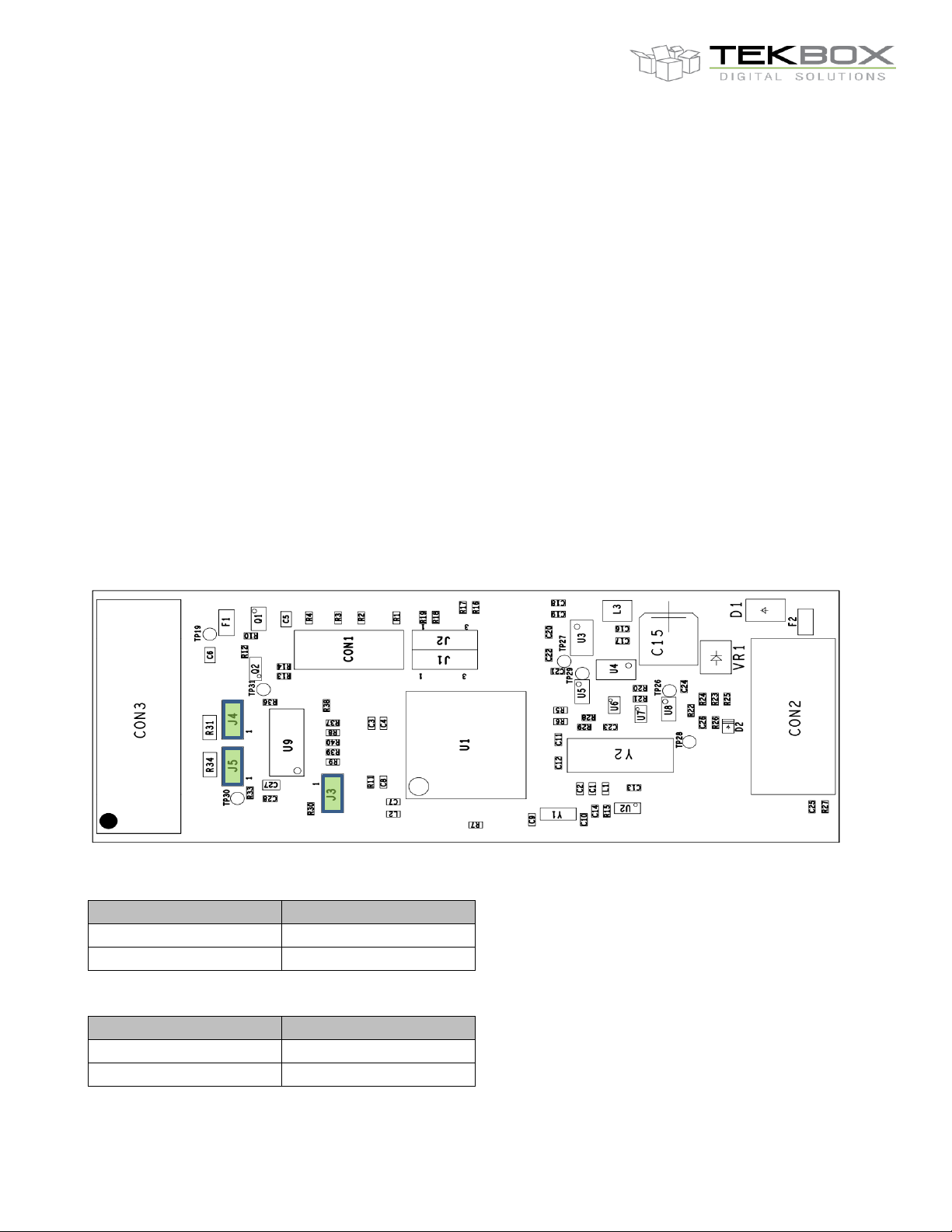
Configuration
J3
Half Duplex
Full Duplex
Configuration
J4 – J5
120 Ω termination
No termination
TBS09S
Modbus Master to SDI-12 Slave Converter
o Modbus RTU
o Baud rate: 19200
o Half or full duplex (configurable)
o 120 Ω termination (configurable)
Supply voltage: 5 – 16 V
Power consumption
o Active mode: 4 mA
o Idle mode: 20µA
Form factor: DINRAIL
3 Calibration and settings
TBS09S doesn’t require any calibration.
It comes factory-configured to operate by default in half duplex with no termination.
This configuration can be changed by the user by setting related jumpers J3/J4/J5 after lifting the housing:
Communication mode:
Modbus termination:
Page 5
V1.8
5
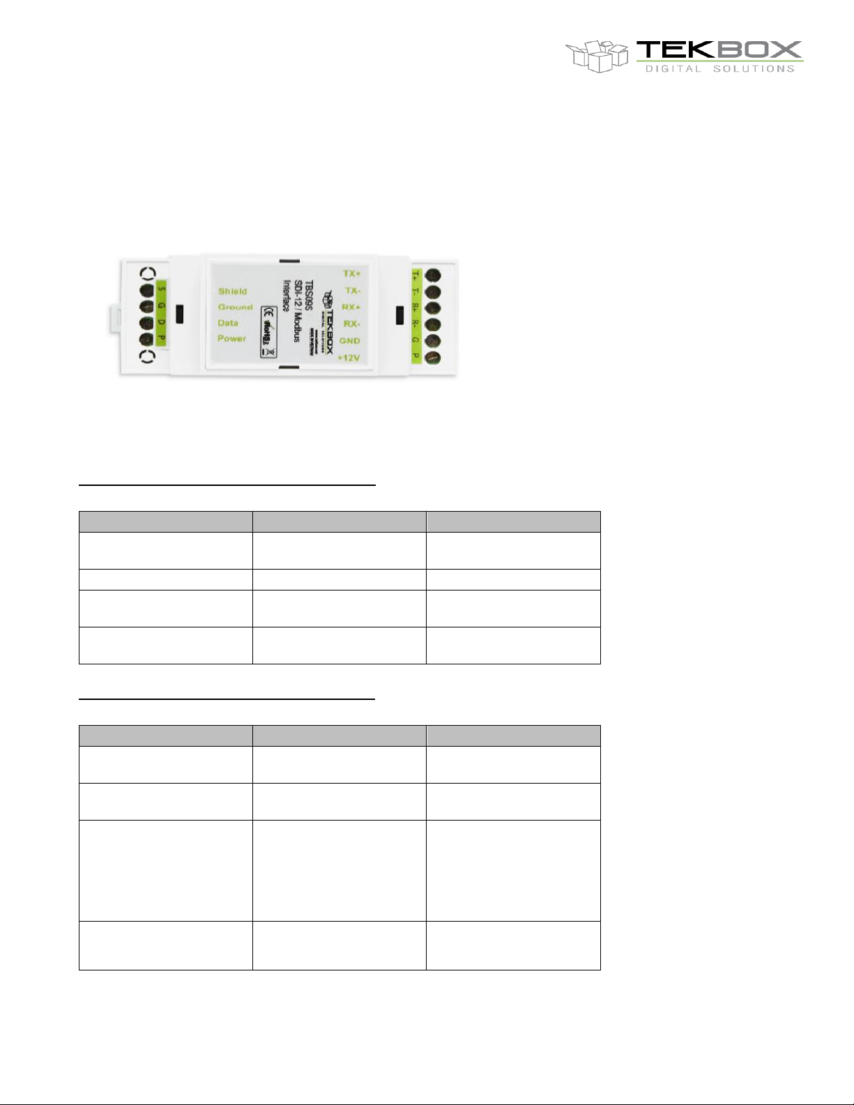
Slot name
Description
Comment
Shield
Cable shield
Connect to sensor’s
cable shield
Ground
Ground
Connect to ground
Data
SDI-12 data line
Connect to SDI-12
sensor data line
Power*
TBS09S supply voltage
input
Connect to +12V external
power supply
Slot name
Description
Comment
T+
TXD+ output
Connect to Modbus
master RXD+
T-
TXD- output
Connect to Modbus
master RXD-
R+
RXD+ input
Connect to Modbus
master TXD+ (full
duplex operation only –
must be left
unconnected in half
duplex)
R-
RXD- input
Connect to Modbus
master TXD- (full duplex
operation only – must
TBS09S
Modbus Master to SDI-12 Slave Converter
4 Connections
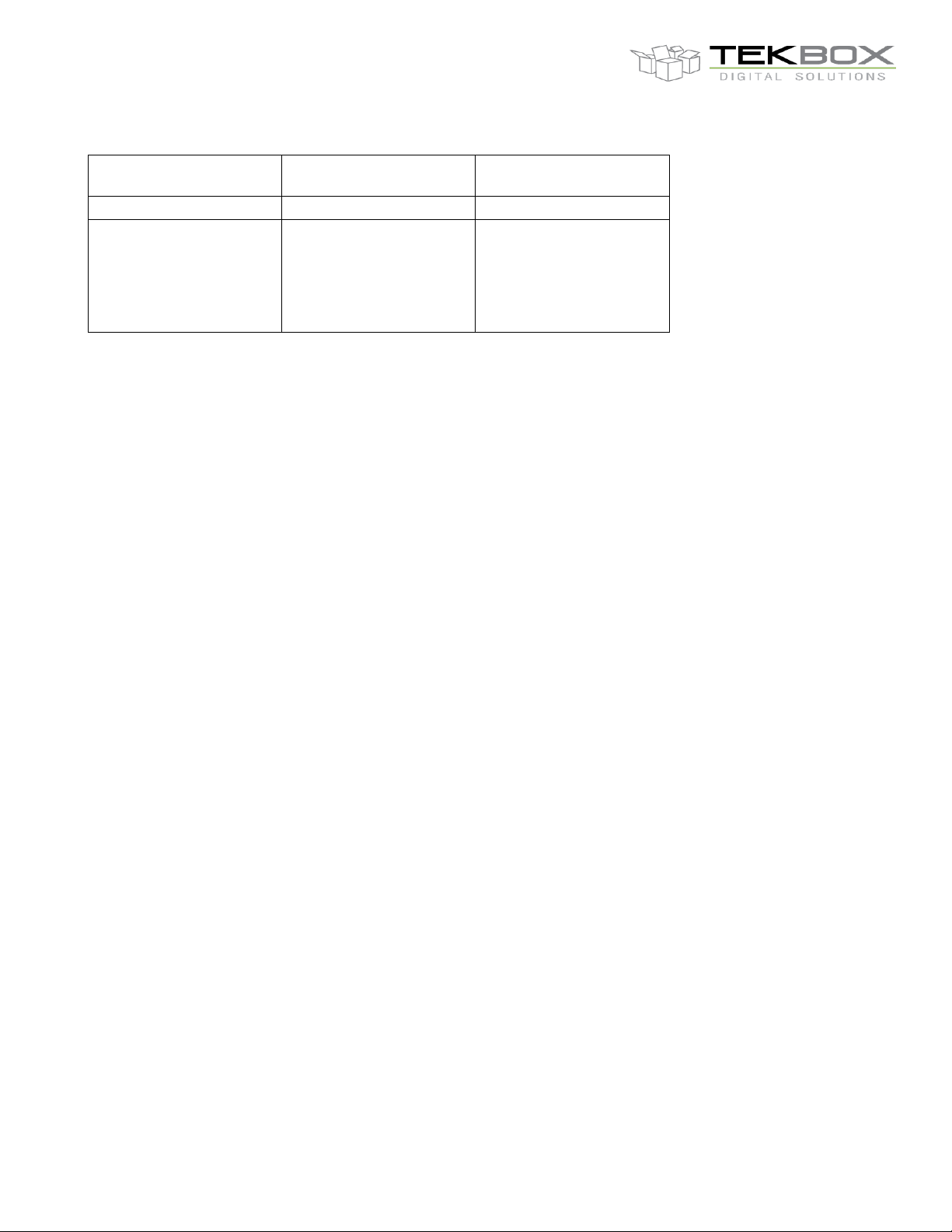
TBS09S provides one 4 slots connector (SDI-12) and one 6 slots connector (RS485):
SDI-12 terminal assignment, from top to bottom:
RS485 terminal assignment, from top to bottom:
Page 6
V1.8
6
be left unconnected in
half duplex)
G
Ground
Connect to ground
P*
SDI-12 sensor supply
voltage output (+12V,
connected to the
converter supply line
through a high side FET
switch)
Connect to SDI-12
sensor power line.
TBS09S
Modbus Master to SDI-12 Slave Converter
*The crossed connectivity is caused by the same converter hardware being used for both the Modbus master to
SDI-12 slave converter and the SDI-12 master to Modbus slave converter. This is subject to being changed in a
future hardware revision.
5 Sending SDI-12 commands through TBS09S
SDI-12 commands are encapsulated by Modbus which acts as a communication layer.
Executing a SDI-12 command over Modbus requires sending 2 Modbus requests:
One request with function code 6 to send the SDI-12 command
One request with function code 4 to get the result of the executed SDI-12 command.
5.1 Supported SDI-12 commands
TBS09S supports only a subset of SDI-12 commands vs SDI-12 v1.3 specification and has a limitation with respect
to Send Data command.
The following commands are supported:
Address Query ?!
Change Address aAb!
Start Measurement aM!
Start Measurement and Request CRC aMC!
Additional Measurements aM1! … aM9!
Additional Measurements and Request CRC aMC1! ... aMC9!
Start Concurrent Measurement aC!
Start Concurrent Measurement and Request CRC aCC!
Additional Concurrent Measurements aC1! … aC9!
Additional Concurrent Measurements and Request CRC aCC1! ... aCC9!
Send Data (*) aD0! … aD9!
Supported SDI-12 address range is aligned with SDI-12 v1.3 specification:
0 – 9
Page 7

V1.8
7
Modbus Master request
Slave Address
Function
Starting Address Hi
Starting Address Lo
Data Hi
Data Lo
Error Check Lo (CRC)
Error Check Hi (CRC)
TBS09S
Modbus Master to SDI-12 Slave Converter
a – z
A – Z
(*): Send Data aD0!...aD9! supports only up to 10 measurements irrespective of the maximum number of
characters that can be returned (75 for a concurrent measurement command, 35 otherwise).
5.2 Modbus default configuration and frames format
5.2.1 Default configuration
TBS09S uses following Modbus configuration:
Protocol: Modbus RTU
Baud rate: 19200, Parity: none
Modbus slave address: 1 (default). It is configurable via Modbus Address Change request within 0x01-
0xFF range
5.2.2 Modbus master to TBS09S: Modbus request format
All Modbus requests sent by the Modbus master (Modbus data logger, Modbus RTU) to TBS09S must be
formatted as described in following table as per Modbus specification.
Each field represents one byte in hexadecimal:
TBS09S uses only Modbus requests with function codes 4 or 6 depending on the command’s purpose.
The CRC must be calculated as per Modbus RTU standard (please note the less significant CRC byte is stored
first and followed by the most significant CRC byte).
Online calculators can be used for this, like https://www.lammertbies.nl/comm/info/crc-calculation and selecting
hexadecimal input type.
5.2.3 TBS09S to Modbus master: Modbus response format
Each field in below tables represents one byte.
Generic response to a Modbus request with function code 4
Page 8

V1.8
8
Modbus Slave response
(TBS09S)
Slave Address
(TBS09S Modbus address)
04
Byte Count
(2*N, N is the number of Input
Registers)
Input Register 1 Hi
Input Register 1 Lo
…
Input Register N Hi
Input Register N Lo
Error Check Lo (CRC)
Error Check Hi (CRC)
Modbus Slave response
(TBS09S)
Slave Address
(TBS09S Modbus address)
06
Register Address Hi
Register Address Lo
Register Value Hi
Register Value Lo
Error Check Lo (CRC)
Error Check Hi (CRC)
Register Address
Command
Description
Modbus configuration commands
0xB000
Modbus slave address change
Change TBS09S Modbus address
SDI-12 commands
0xA000
?!
Address Query command
0xA100
aAb!
Change Address command
0x0010
aM!
Start Measurement
0x0011
aM1!
Additional Measurements
0x0012
aM2!
Additional Measurements
TBS09S
Modbus Master to SDI-12 Slave Converter
Generic response to a Modbus request with function code 6
Note: in this case, the response is the mirror of the corresponding request.
5.3 TBS09S Modbus registers mapping
All available SDI-12 commands that can be sent over Modbus are mapped over a set of registers.
The following table lists all TBS09S Modbus registers with their associated commands (‘a’ refers to SDI-12 address
as per SDI-12 standard and is subsequently used as is in this document):
Page 9

V1.8
9
0x0013
aM3!
Additional Measurements
0x0014
aM4!
Additional Measurements
0x0015
aM5!
Additional Measurements
0x0016
aM6!
Additional Measurements
0x0017
aM7!
Additional Measurements
0x0018
aM8!
Additional Measurements
0x0019
aM9!
Additional Measurements
0x0020
aMC!
Additional Measurements and
Request CRC
0x0021
aMC1!
Additional Measurements and
Request CRC
0x0022
aMC2!
Additional Measurements and
Request CRC
0x0023
aMC3!
Additional Measurements and
Request CRC
0x0024
aMC4!
Additional Measurements and
Request CRC
0x0025
aMC5!
Additional Measurements and
Request CRC
0x0026
aMC6!
Additional Measurements and
Request CRC
0x0027
aMC7!
Additional Measurements and
Request CRC
0x0028
aMC8!
Additional Measurements and
Request CRC
0x0029
aMC9!
Additional Measurements and
Request CRC
0x0030
aC!
Start Concurrent Measurements
0x0031
aC1!
Additional Concurrent
Measurements
0x0032
aC2!
Additional Concurrent
Measurements
0x0033
aC3!
Additional Concurrent
Measurements
0x0034
aC4!
Additional Concurrent
Measurements
0x0035
aC5!
Additional Concurrent
Measurements
0x0036
aC6!
Additional Concurrent
Measurements
0x0037
aC7!
Additional Concurrent
Measurements
0x0038
aC8!
Additional Concurrent
Measurements
TBS09S
Modbus Master to SDI-12 Slave Converter
Page 10

V1.8
10
0x0039
aC9!
Additional Concurrent
Measurements
0x0040
aCC!
Additional Concurrent
Measurements and Request CRC
0x0041
aCC1!
Additional Concurrent
Measurements and Request CRC
0x0042
aCC2!
Additional Concurrent
Measurements and Request CRC
0x0043
aCC3!
Additional Concurrent
Measurements and Request CRC
0x0044
aCC4!
Additional Concurrent
Measurements and Request CRC
0x0045
aCC5!
Additional Concurrent
Measurements and Request CRC
0x0046
aCC6!
Additional Concurrent
Measurements and Request CRC
0x0047
aCC7!
Additional Concurrent
Measurements and Request CRC
0x0048
aCC8!
Additional Concurrent
Measurements and Request CRC
0x0049
aCC9!
Additional Concurrent
Measurements and Request CRC
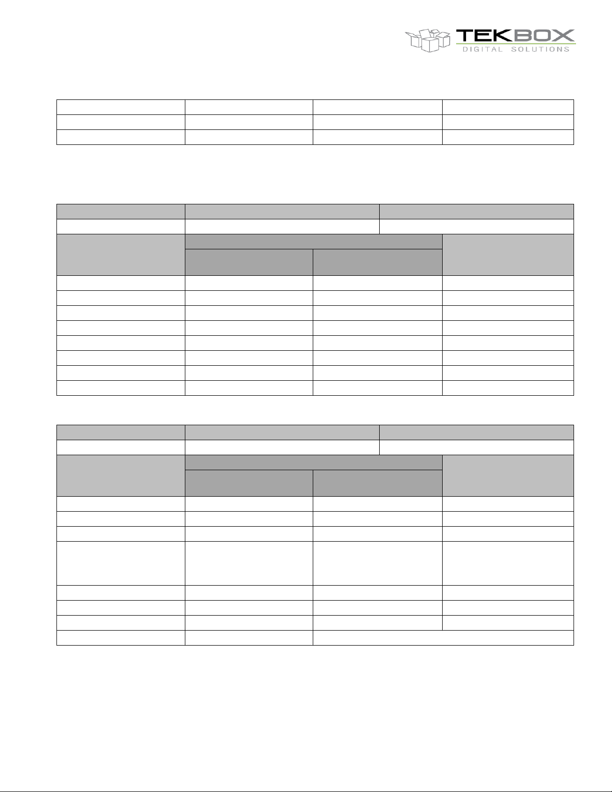
Register address
Command
Description
0xB000
Modbus slave address change
Change TBS09S Modbus address
Modbus Master request
format
Example: change TBS09S Modbus address from 1 to 2
Modbus Slave response
format
Modbus Master request
Modbus Slave (TBS09S)
response
TBS09S Modbus Address
01
01
TBS09S Modbus Address
06
06
06
06
B0
B0
B0
B0
00
00
00
00
00
00
00
00
New TBS09S Modbus
Address
02
02
New TBS09S Modbus
Address
TBS09S
Modbus Master to SDI-12 Slave Converter
5.4 TBS09S Modbus requests detailed description
Following tables show each defined Modbus requests and the corresponding response format along with an
example.
All fields represent a byte coded in hexadecimal.
5.4.1 Modbus slave address change
Page 11
V1.8
11
Range: 0x01 – 0xFF
Error Check Lo (CRC)
2E
2E
Error Check Lo (CRC)
Error Check Hi (CRC)
CB
CB
Error Check Hi (CRC)
Register address
Command
Description
0xA000
Query sensor’s SDI-12 address
Sends ?! SDI-12 command
Modbus Master request
format
Example: returned sensor’s SDI-12 address is 2
Modbus Slave response
format
Modbus Master request
Modbus Slave (TBS09S)
response
TBS09S Modbus Address
01
01
TBS09S Modbus Address
06
06
06
06
A0
A0
A0
A0
00
00
00
00
00
00
00
00
00
00
00
00
Error Check Lo (CRC)
AB
AB
Error Check Lo (CRC)
Error Check Hi (CRC)
CA
CA
Error Check Hi (CRC)
Register address
Command
Description
0xA000
Read ?! response
Read sensor’s SDI-12 address
Modbus Master request
format
Example: returned sensor’s SDI-12 address is 2
Modbus Slave response
format
Modbus Master request
Modbus Slave (TBS09S)
response
TBS09S Modbus Address
01
01
TBS09S Modbus Address
04
04
04
04
A0
A0
02
02
00
00
32
(ASCII code: 0x32 =>
SDI-12 address=2)
SDI-12 Address
(represented by its ASCII
code)
00
00
00
00
00
01
AC
Error Check Lo (CRC)
Error Check Lo (CRC)
13
50
Error Check Hi (CRC)
Error Check Hi (CRC)
CA
TBS09S
Modbus Master to SDI-12 Slave Converter
5.4.2 Query sensor’s SDI-12 address (SDI-12 command: ?!)
Send SDI-12 ?! command
Read returned SDI-12 address
Page 12

V1.8
12
Register address
Command
Description
0xA100
Change sensor’s SDI-12 address
Sends aAb! SDI-12 command
Modbus Master request
format
Example: change SDI-12 address from 3 to 4
Modbus Slave response
format
Modbus Master request
Modbus Slave (TBS09S)
response
TBS09S Modbus Address
01
01
TBS09S Modbus Address
06
06
06
06
A1
A1
A1
A1
00
00
00
00
Current SDI-12 Address
(represented by its ASCII
code)
33
(ASCII code: 0x33 =>
SDI-12 address=3)
33
Current SDI-12 Address
(represented by its ASCII
code)
New SDI-12 Address
(represented by its ASCII
code)
34
(ASCII code: 0x34 =>
SDI-12 address=4)
34
New SDI-12 Address
(represented by its ASCII
code)
Error Check Lo (CRC)
BF
BF
Error Check Lo (CRC)
Error Check Hi (CRC)
11
11
Error Check Hi (CRC)
TBS09S
Modbus Master to SDI-12 Slave Converter
5.4.3 Change sensor’s SDI-12 address (SDI-12 command: aAb!)
Send SDI-12 aAb! command
5.4.4 SDI-12 Measurement (SDI-12 commands: aM!/aMC!/aMx!/aMCx!/aC!/aCC!/aCCx!)
The procedure is similar to a regular SDI-12 communication to get sensor’s measurements, except that the SDI12 commands are sent over Modbus.
This implies:
Send a SDI-12 measurement command (aM!/aMC!/aMx!/aMCx!/aC!/aCC!/aCCx!)
Get the specified time (ttt) and the number of measurement values (n / nn)
Send the SDI-12 data command (aD0! … aD9!)
Retrieve the measurements
Step 1 - Send a Measurement Command to the SDI-12 sensor:
TBS09S can transmit any of the following measurement commands to a SDI-12 sensor: aM!...aM9,
aMC!…aMC9!, aC!..aC9!, aCC!..aCC9!
Note: refer to TBS09S Modbus registers mapping for a complete list of supported SDI-12 commands and the
corresponding register address.
Page 13

V1.8
13
Register address
Command
Description
SDI-12 register address
SDI-12 Measurement Command
aM!/aMC!/aMx!/aMCx!/aC!/aCC!/aCCx!
Modbus Master request
format
Example: send SDI-12 command bM!
Modbus Slave response
format
Modbus Master request
Modbus Slave (TBS09S)
response
TBS09S Modbus Address
01
01
TBS09S Modbus Address
06
06
06
06
SDI-12 command register
address Hi
00
(M! register address Hi)
00
SDI-12 command register
address Hi
SDI-12 command register
address Lo
10
(M! register address Lo)
10
SDI-12 command register
address Lo
00
00
00
00
SDI-12 address
(represented by its ASCII
code)
62
(ASCII code: 0x62 =>
SDI-12 address=b)
62
SDI-12 address
(represented by its ASCII
code)
Error Check Lo (CRC)
09
09
Error Check Lo (CRC)
Error Check Hi (CRC)
E6
E6
Error Check Hi (CRC)
Register address
Command
Description
0xmm10
(mm: SDI-12 address
ASCII code)
Read SDI-12 measurement command
response
Read Specified time (ttt) and Number of
Measurements (n/nn)
Modbus Master request
format
Example: time=1s and 2 measurement values
Modbus Slave response
format
Modbus Master request
Modbus Slave (TBS09S)
response
TBS09S Modbus Address
01
01
TBS09S Modbus Address
04
04
04
04
SDI-12 address
(represented by its ASCII
code)
62
(ASCII code 0x62 =>
04
04
TBS09S
Modbus Master to SDI-12 Slave Converter
Send SDI-12 measurement command(aM!/aMC!/aMx!/aMCx!/aC!/aCC!/aCCx!)
Step 2 – Get the specified time and the number of measurements
As per SDI-12 standard, the measurements commands will return the specified time and the number of
measurement values:
M!/MC!/M1!...M9!/MC1!...MC9!
o Specified time: ttt
o Number of measurement values: n
C!/CC!/C1!...C9!/CC1!...CC9!
o Specified time: ttt
o Number of measurement values: nn
Page 14

V1.8
14
SDI-12 address=b)
10
10
00
00
00
00
01
Specified time ttt
02
02
00
00
Error Check Lo (CRC)
6F
02
Number of measurements
n/nn
Error Check Hi (CRC)
B6
2B
Error Check Lo (CRC)
85
Error Check Hi (CRC)
Register address
Command
Description
0x00Dm (m: 0 to 9)
Send SDI-12 Data command
Send aDm! (m: 0 to 9)
Modbus Master request
format
Example: send SDI-12 data command bD0!
Modbus Slave response
format
Modbus Master request
Modbus Slave (TBS09S)
response
TBS09S Modbus Address
01
01
TBS09S Modbus Address
06
06
06
06
00
00
00
00
SDI-12 Data Command
(D0! To D9! coded as
0xD0 to 0xD9)
D0
(0xD0 => D0! Data
command)
D0
SDI-12 Data Command
(D0! To D9! coded as
0xD0 to 0xD9)
00
00
00
00
SDI-12 address
(represented by its ASCII
code)
62
(ASCII code: 0x62 =>
SDI-12 address=b)
62
SDI-12 address
(represented by its ASCII
code)
Error Check Lo (CRC)
09
09
Error Check Lo (CRC)
Error Check Hi (CRC)
DA
DA
Error Check Hi (CRC)
Value
Value0
Value1
Value2
Value3
Value4
Value5
Value6
Value7
Value8
Value9
Index
0x00
0x01
0x02
0x03
0x04
0x05
0x06
0x07
0x08
0x09
TBS09S
Modbus Master to SDI-12 Slave Converter
Step 3 - Send SDI-12 Data Command to the SDI-12 sensor
Send the data command (any of aD0!...aD9!):
Step 4 – Retrieve the measurements
The Send Data command is implemented in TBS09S so it can handle up to 10 values (this is a limitation vs SDI12 v1.3 standard).
aDx! will then return a maximum of 10 measurements as follows:
a<Value0><Value1><Value2><Value3><Value4><Value5><Value6><Value7><Value8><Value9>
Each value is identified by its index:
and is stored in hexadecimal floating point over 4 bytes (0xByte3Byte2Byte1Byte0) and must be then individually
fetched with a specific modbus request.
Page 15
V1.8
15
Register address
Command
Description
0xmmii
mm: SDI-12 address
ASCII code, ii: value index
(0x00-0x09)
Retrieve aDx! value
Return aDx! value at index
Modbus Master request
format
Example: retrieve the 6th value returned by bD0!
Modbus Slave response
format
Modbus Master request
Modbus Slave (TBS09S)
response
TBS09S Modbus Address
01
01
TBS09S Modbus Address
04
04
04
04
SDI-12 address
(represented by its ASCII
code)
62
(ASCII code 0x62 =>
SDI-12 address=b)
04
04
Value Index
(00x00 to 0x09)
05
(0x05 => index of the 6th
value returned by bD0!)
41
Value – Byte3
00
00
CF
Value – Byte 2
02
02
1E
Value – Byte 1
Error Check Lo (CRC)
7E
B8
Value – Byte 0
Error Check Hi (CRC)
72
D6
Error Check Lo (CRC)
55
Error Check Hi (CRC)
TBS09S
Retrieve a measurement
Modbus Master to SDI-12 Slave Converter
The above example shows how to read the 6th measurement from a temperature sensor with SDI-12 interface.
The hexadecimal floating point value is 0x41CF1EB8; once converted to decimal representation this results in
+25.89 C.
Online hexadecimal floating point to decimal converters can be used to make the measurement readable like
https://www.h-schmidt.net/FloatConverter/IEEE754.html
5.5 TBS09S / SDI-12 sensor communication flow example
The below example shows how to measure and read the soil moisture and soil temperature over Modbus by using
SDI-12 TBSMP03 Tekbox sensor (https://www.tekbox.com/product/tbsmp03-sdi-12-soil-moisture-temperature-
probe/) connected to TBS09S.
With this test setup:
TBS09S Modbus slave address is 1
TBSMP03 SDI-12 address is 0
TBSMP03 returns 2 parameters, soil temperature first and then the soil moisture
Page 16

V1.8
16
Version
Date
Author
Changes
V1.0
9.8.2018
Thinh
Creation of the document
V1.1
9.19.2019
Thinh
Update new command
V1.5
24.6.2020
Hoa Hoang
Updated naming to Modbus Master to SDI 12 Slave
Converter
V1.6
15.7.2020
Mayerhofer
Complete rework of the document
V1.7
17.7.2020
Philippe
Updated link in 5.5
V1.8
2.4.2021
Mayerhofer
Updated drawing in chapter 1
TBS09S
Modbus Master to SDI-12 Slave Converter
[Modbus Master] 01 06 00 11 00 30 D9 DB Modbus Master sends 0M1! to the sensor
[TBS09S] 01 06 00 11 00 30 D9 DB TBS09S responds with ACK
[Modbus Master] 01 04 30 10 00 02 7F 0E Modbus Master reads ttt and n
[TBS09S] 01 04 04 00 01 00 02 2B 85 TBS09S returns ttt=1s and n=2 values
Modbus Master waits 1s
[Modbus Master] 01 06 00 D0 00 30 88 27 Modbus Master sends 0D0! to the sensor
[TBS09S] 01 06 00 D0 00 30 88 27 TBS09S responds with ACK
[Modbus Master] 01 04 30 00 00 02 7E CB Modbus Master reads 1
[TBS09S] 01 04 04 41 2D 99 99 8B FF TBS09S response data = 41,2D,99,99 =10.85
[Modbus Master] 01 04 30 01 00 02 2F 0B Modbus Master reads 2ndparameter (temperature)
[TBS09S] 01 04 04 41 DB 70 A4 F8 FF TBS09S response data = 41,DB,70,A4 = 27.43
6 SDI-12
SDI-12 is a standard for interfacing data recorders with microprocessor-based sensors. SDI-12 stands for
serial/digital interface at 1200 baud. It can connect multiple sensors with a single data recorder on one cable. It
supports up to 60 meter cable between a sensor and a data logger.
The SDI-12 standard is prepared by
SDI-12 Support Group
(Technical Committee)
165 East 500 South
River Heights, Utah
435-752-4200
435-752-1691 (FAX)
http://www.sdi-12.org
The latest standard is version V1.4 which dates from Jan 10th, 2019. The standard is available on the website of
the SDI-12 Support Group.
st
parameter (moisture)
7 History
 Loading...