

Page 1

V1.0
TBS06
-TS
RS232 to
SDI-12
Interface
–
Fibox
- and Dinrail
TBS06-TS
RS232 to SDI-12 converter and bus sniffer
The TBS06-TS (DR) RS232 to SDI-12 Converter is an interface for connecting a PC, data logger or
RTU to one or more sensors with SDI-12 interface. The TBS06-TS connects to the RS232
interface and provides a SDI-12 compliant data interface. The TBS06-TS is a versatile tool for
everyone who designs sensors and data recorders or who installs, tests or maintains SDI-12 based
data acquisition systems. Furthermore it includes a SDI-12 bus sniffer mode.
It is available in a IP67 housing from Fibox or in a Dinrail housing.
Features
RS232 toSDI-12 Interface
Transfer Mode / Monitor Mode
Plug and play
No driver required
Selectable data rate: 4800 - 38400
Baud
5V … 12V supply voltage
Low power mode
Spring loaded terminal blocks
IP67 housing or Dinrail housing
Operating Temperature Range:
- 40°C … + 85°C
Target Applications
SDI-12 Data Recording
SDI-12 Field Installations
SDI-12 Interface Debugging
SDI-12 Sensor Testing
Factory 4, F5, Lot I-3B-1 | Saigon Hi-Tech Park | Tan Phu Ward, District 9 | Ho Chi Minh City | Tel +84 (83)5471340
© 2021 Tekbox Digital Solutions
E-mail office@tekbox.com| www.tekbox.com
1
Page 2

V1.0
TBS06-TS
RS232 to SDI-12 Interface
Contents
1 INTRODUCTION 3
1.1 P
1.2 M
2 APPLICATION 4
3 FUNCTIONAL DESCRIPTION 4
3.1 O
3.2 SDI-12 T
3.3 SDI-12 M
4 HARDWARE DESCRIPTION 5
4.1 B
4.2 C
4.3 C
5 SDI-12 BASICS 10
6 SETTING UP TBS06-TS 10
6.1 U
6.2 H
6.3 O
7 TRANSFER MODE 11
8 SDI-12 MONITOR MODE 12
RODUCT FEATURES
ECHANICAL DIMENSIONS
VERVIEW
OARD OVERVIEW
ONNECTIONS – FIBOX VARIANT
ONNECTIONS –
SER INTERFACE
ARDWARE INTERFACE
PERATING MODES
4
RANSFER MODE
ONITOR MODE
3
3
4
5
5
DIN-
RAIL VARIANT
10
11
11
7
8
9 ORDERING INFORMATION 14
10 HISTORY 14
2
Page 3

V1.0
TBS06-TS
RS232 to SDI-12 Interface
1 Introduction
SDI-12 is a standard for interfacing data recorders with microprocessor-based sensors. SDI-12 stands for
serial/digital interface at 1200 baud. It can connect multiple sensors with a single data recorder on one cable.
It supports up to 60 meter cable between a sensor and a data logger.
The SDI-12 standard is prepared by
SDI-12 Support Group
(Technical Committee)
165 East 500 South
River Heights, Utah
435-752-4200
435-752-1691 (FAX)
http://www.sdi-12.org
The latest standard is version V1.3 and dates from July 18th, 2005. The standard is available on the web site
of the SDI-12 Support Group.
TBS06-TS implements all functions for interfacing SDI-12 sensors to a RTU, data logger or PC with RS232
interface.
It is a plug and play solution for controlling or testing of sensors with SDI-12 interface.
1.1 Product Features
RS232 to SDI-12 Interface based on TBS01 SDI-12 module
Transfer Mode
Plug and play
No driver required
Selectable data rate: 4800 - 38400 Baud
6V … 16V supply voltage
Current consumption: 6 mA in “always on mode”; less than 250µA in “auto power management
mode”
Fibox IP67 housing variant: Weidmueller spring loaded terminal blocks
Dinrail housing variant: screw terminal blocks
Operating Temperature Range: - 40°C … + 85°C
1.2 Mechanical dimensions
Fibox housing: Fibox PC 081206
http://www.fibox.com/catalog/1999/product/611/7032580_ENG3.html
Dinrail housing: Bud Industries DMB-4770
http://www.budind.com/pdf/hb4770.pdf
3
Page 4
V1.0
TBS06-TS
RS232 to SDI-12 Interface
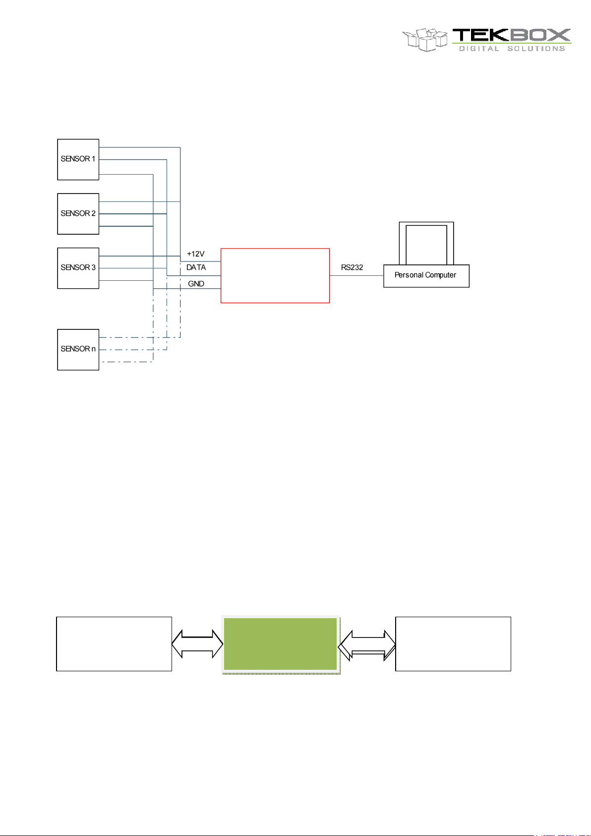
2 Application
RS232 to SDI-12 Converter
TBS06
Figure 1 –TBS06-TS Application, standard setup for controlling / testing sensors
3 Functional Description
3.1 Overview
The SDI-12 standard defines a set of commands to configure sensors and to initiate measurements. Upon
receiving specific commands, the sensor may carry out internal tasks, respond with information on
conversion time or send measurement data.
SDI-12 commands typically are ASCII strings generated by the data recorder/controller firmware. TBS06-TS
can be controlled by a PC application or hyper terminal and converts the command strings to the logic levels
and baud rate specified by the SDI-12 standard. Furthermore TBS06-TShandles breaks, marks and all other
details of the SDI-12 protocol.
Upon receiving data or status information originated by a Sensor, TBS06-TS extracts the corresponding
ASCII strings and sends it to COM Port of the PC.
3.2 SDI-12 Transfer mode
Hyper terminal or
customised PC
application
RS232 / SDI-12
Figure 2 – TBS06-TS basic application setup
The application is built based on a SDI-12 Recorder Protocol Stack Module. It receives commands from the
RS232 Interface (e.g. via data logger, RTU or PC), and transfers the commands to the SDI Interface, waits
for sensor response and transfers the response (measurement results, etc.) back to the RS232 Interface of
the data logger, RTU or PC. All SDI-12 commands are supported.
4
Interface
Sensor(s)
Page 5
V1.0
TBS06-TS
RS232 to SDI-12 Interface
3.3 SDI-12 Monitor mode
In SDI-12 monitor mode, TBS06-TS monitors the data traffic between recorder and sensor(s). This feature is
useful in setting up or debugging SDI-12 installations. More details are available here.
Hyper terminal or
customised PC
application
Recorder
RS232 / SDI-12
Converter
Figure 3 –TBS06-TS application; setup for monitor mode
Sensor(s)
4 Hardware Description
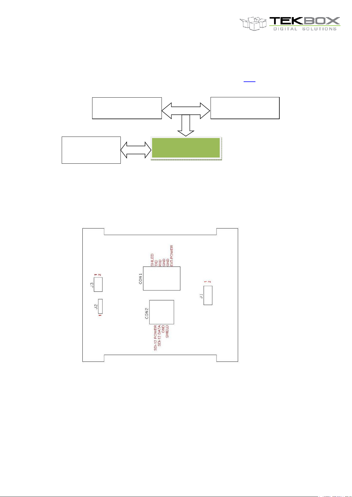
4.1 Board overview
Figure 4 – Board Connections, Jumper Settings of Fibox variant
5
Page 6

V1.0
TBS06-TS
RS232 to SDI-12 Interface
Figure 5 – Board Connections, Jumper Settings of Dinrail variant
6
Page 7

V1.0
TBS06-TS
RS232 to SDI-12 Interface
4.2 Connections – Fibox Variant
TBS06-TS supports RS232 and gives access to the UART interface of the on board SDI-12 module.
CON2: RS232 interface connector; Pin 1-2 of J1 : access to UART interface
4 Pin terminal block:
CON2 – SDI-12 Interface
Shield: connect to the shield of the SDI-12 cable or leave it unconnected
Ground: connect to the GND wire of the SDI-12 cable
SDI-12 data: connect to the data wire of the SDI-12 cable
SDI-12 Power: connect to the positive supply voltage wire of the SDI-12 cable; the SDI-12 supply
voltage is directly connected to the RS232 supply line
6 Pin terminal block:
Shield: connect to the shield or leave it unconnected
Ground1: connect to the GND of supply for TBS06-TS
EXT- Power: connect to an external power supply (6V…16V)
Ground2: connect to the GND of COM port ( Pin 5 of DB9)
TxD: connect to RXD of the RS232 interface ( Pin 2 of DB9)
RxD: connect to TxD of the RS232 interface ( Pin 3 of DB9)
Jumper 1 (SDI12 module connectivity)
Connect to RS232 Interface:
Jumper: 5-7 and 6-8
Connects to RS232 ines of CON1
Access to UART Interface of the on-board TBS01 SDI-12 module:
Jumper: 3-5 and 4-6
Connect UART to pin 1-2 of J1
Jumper 2 (Power management)
Jumper 1-2: Always On (6 mA); default factory setting
Jumper 2-3: Power saving mode (>250uA), TBS06-TS will wakup automatically when data is present
at the Rx pin, and switches into sleep mode 2.5 seconds after RX becomes idle
Jumper 3 (Baud Rate selection)
4800 Baud: jumper 1-3, 2-4
9600 Baud: jumper 3-5, 2-4
19200 Baud: jumper 1-3, 4-6; default factory setting
38400 Baud: jumper 3-5, 4-6
7
Page 8

V1.0
TBS06-TS
RS232 to SDI-12 Interface
Other communication settings:
8 Bits
No Parity
1 Stop Bit
No Handshake
4.3 Connections – DIN-rail variant
RS232 Side, from left to right:
Cable shield
RS232 TX (TBS06-TSDR output)
RS232 RX (TBS06-TSDR input)
Ground
Ground
6-12V external supply input
SDI-12 Side, from left to right:
Cable shield
Ground
SDI-12 data line
SDI-12 supply voltage output
Figure 6 – Connections
TBS06-TSDR is shipped with RS232 jumpered to 19200 Baud.
Following other Baud rates can be factory - jumpered upon specification in the order: 4800, 9600 and 32400
Baud.
8
Page 9

V1.0
TBS06-TS
RS232 to SDI-12 Interface
Other communication settings:
8 Bits
No Parity
1 Stop Bit
No Handshake
4 Pin terminal block:
CON1 – SDI-12 Interface
Shield: connect to the shield of the SDI-12 cable or leave it unconnected
Ground: connect to the GND wire of the SDI-12 cable
SDI-12 data: connect to the data wire of the SDI-12 cable
SDI-12 Power: connect to the positive supply voltage wire of the SDI-12 cable; the SDI-12 supply
voltage is directly connected to the RS232 supply line
6 Pin terminal block:
CON2 – Power supply & RS232 interface
+12V: connect to an external power supply (7V…12V)
Ground1: connect to the GND of supply for TBS06-TSDR
Ground2: connect to the GND of COM port ( Pin 5 of DB9)
RxD: connect to TxD of the RS232 interface ( Pin 3 of DB9)
TxD: connect to RXD of the RS232 interface ( Pin 2 of DB9)
Shield: connect to the shield or leave it unconnected
Shield, Ground 1, Ground 2 and SDI-12 Ground are internally connected together
Jumper settings
Refer to Figure 4
Baud rate
4800 Baud set jumpers J6, J8
9600 Baud set jumpers J6, J9
19200 Baud set jumpers J4, J8
38400 Baud set jumpers J4, J9
Power management:
Jumper J2, position 1-2 jumpered: Always On (6 mA); default factory setting
Jumper J2, position 2-3 jumpered: Power saving mode (>250uA), TBS06-TS will wakup automatically when
data is present at the Rx pin, and switches into sleep mode 2.5 seconds after RX becomes idle
9
Page 10

V1.0
TBS06-TS
RS232 to SDI-12 Interface
5 SDI-12 Basics
SDI-12 is a serial data communication standard for interfacing multiple sensors with a data recorder
SDI-12 uses a shared bus with 3 wires: power (12V), data, ground
Data rate: 1200 baud
Each sensor at the bus gets a unique address which is in the range ASCII [0-9, a-z, A-Z]. The default
address of every sensor is ASCII[0]. When setting up a SDI-12 sensor network, every sensor needs to be
configured with a unique address. This can be done using the Change Address Command.
A sensor typically can measure one or more parameters.
Sensor manufacturers usually specify Extended Commands to configure or calibrate sensors. This
commands are specified by the manufacturer, but they follow the command structure specified by SDI-12.
A typical recorder/sensor measurement sequence proceeds as follows:
1) The data recorder wakes all sensors on the SDI-12 bus with a break.
2) The recorder transmits a command to a specific, addressed sensor, instructing it to make a measurement.
3) The addressed sensor responds within 15.0 milliseconds returning the maximum time until the
measurement data will be ready and the number of data values it will return.
4) If the measurement is immediately available, the recorder transmits a command to the sensor instructing it
to return the measurement result(s). If the measurement is not ready, the data recorder waits for the sensor
to send a request to the recorder, which indicatesthat the data are ready. The recorder then transmits a
command to get the data.
5) The sensor responds, returning one or more measurement results
SDI-12 command structure:
Each SDI-12 command is an ASCII string with up to 5 characters, starting with the sensor address and
terminated by a ! character.
Example:
Send Identification Command 0I!
0 is the sensor address (sensor zero). Upon receiving this command, the sensor will send an ASCII string
containing sensor address, SDI-12 compatibility number, company name, sensor model number, sensor
version number and sensor serial number.
The standard process to carry out a measurement is to send a measurement request upon which the sensor
responds with the time that is required to carry out the measurement and the number of data items being
returned. After waiting the time that the sensor requires to carry out the measurement, the data recorder
sends a Read Command to get the measurement results.
Example:
Start Measurement Command 0M1!
Sensor 0 might respond 00302 which means the measurement will take 30 seconds and deliver 2 values.
After min. 30 seconds, the data recorder can send the Read Data Command 0D0! to which Sensor 0 might
reply 0+27+1050. +27+1050 is the two measurement results which may be 27°C and 1050 milibar.
The response string of a sensor is always in ASCII format and may contain up to 40 or up to 80 characters,
depending on the type of command. Out of 40 or 80 characters, the values part of the response string may
contain up to 35 or 75 characters.
6 Setting up TBS06-TS
6.1 User Interface
Any RTU, data logger or PC hyper terminal (e.g.: Windows Hyper Terminal, Terminal V1.9B, RealTerm,
Docklight or specific application software such as LabVIEW)
10
Page 11

V1.0
TBS06-TS
RS232 to SDI-12 Interface
Set hyper terminal to 19200 baud, 8 Bits, No Parity, 1 Stop Bit, No Handshake
6.2 Hardware Interface
Figure 7 – RS232 connection
6.3 Operating modes
TBS06-TS supports two operating modes:
Transfer mode
o This mode allows sending SDI-12 commands to SDI-12 sensors over RS232.
Monitor mode
o In this mode the module operates as a SDI-12 bus sniffer mode
Default mode
o The default mode when powering up the module for the first time is transfer mode.
Both modes are exclusive but it is possible to switch from one mode to another:
run sdi monitor to enter monitor mode and act as a SDI-12 bus sniffer.
run sdi recorder to enter transfer mode and send SDI-12 commands.
7 Transfer mode
In transfer mode, SDI-12 commands can be sent over RS232 to SDI-12 sensors connected to TBS06-TS.
11
Page 12

V1.0
r
un
sdi monitor
r
un
sdi recorder
TBS06-TS
RS232 to SDI-12 Interface
On hyper terminal, send SDI-12 commands to read data from sensor.
Notice: every SDI-12 command must be terminated by CR/LF character (0x0D, 0x0A)
Figure 8 – Example: SDI-12 command flow on a terminal application
8 SDI-12 Monitor mode
TBS06-TS can also be used as a SDI-12 bus sniffer module that captures all SDI-12 commands and
responses passing on the bus.
In SDI-12 monitor mode, the TBS06-TS is connected in parallel to a data recorder and sensor(s) and
monitors the data on the SDI-12 interface.
TBS06-TS can then operate in two different modes: transfer and monitor.
By default, and then whenever TBS06-TS is powered up/reset, the transfer mode is active.
Switching from one mode to another is done by issuing a specific command from the PC terminal application
connected to the RS232 port:
Command (ASCII format with \r\n termination) Description
\r\n
\r\n
Switch to Monitor mode
Switch to recorder (transfer) mode
12
Page 13

V1.0
TBS06-TS
RS232 to SDI-12 Interface
The setup of the module in this mode is like transfer mode except for these points:
No external power supply is required (otherwise it may damage the board). TBS06-TS power supply
pins +12V and GND from the 6 pins connector must be left unconnected.
TBS06-TS 4 pins SDI-12 interface connector must be connected to the data logger/recorder SDI-12
bus
The data logger/recorder must constantly deliver power on the SDI-12 power line
Once setup, the SDI-12 bus monitoring can be done as described below:
Open the COM port from the PC terminal application
Switch to SDI-12 Monitor mode
13
Page 14

V1.0
TBS06-TS
RS232 to SDI-12 Interface
Monitor the SDI-12 bus while sending commands from the data logger
Switching back to transfer mode can be done at any time by sending from the PC terminal application the
following command in ASCII: run sdi recorder\r\n (or run sdi recorder if the terminal application automatically
appends \r\n).
9 Ordering Information
Part Number Description
TBS06-TS
TBS06-TS-DR
Default baud rate is 19200 Baud; default power management setting is “Always On”
If you want different settings, please specify in your order
RS232 to SDI-12 interface in IP67 housing – Transfer mode, Monitor
mode
RS232 to SDI-12 interface in DIN-rail housing – Transfer mode, Monitor
mode
Table 1 – Ordering Information
10 History
Version Date Author Changes
V1.0 27.01.2021 Philippe Hervieu Creation
Table 2 – History
14
 Loading...