

Page 1
V1.0
1
TBRFH1 SERIES
RF HOUSINGS
The TBRFH1 series of RF housings are ideal for prototyping RF building blocks operating up
to 6 GHz. The housings consists of a 1 inch aluminium profile with mechanically matching RF
connectors on each end. The user can select a wide range of RF connector combinations,
various housing lengths and optional feed through capacitors. The housings come with RF
absorbing pads to suppress coupling and cavity resonance. Solderable sheet metal ground
pads, sandwiched between the connectors and the aluminium profile simplify establishing the
ground connection.
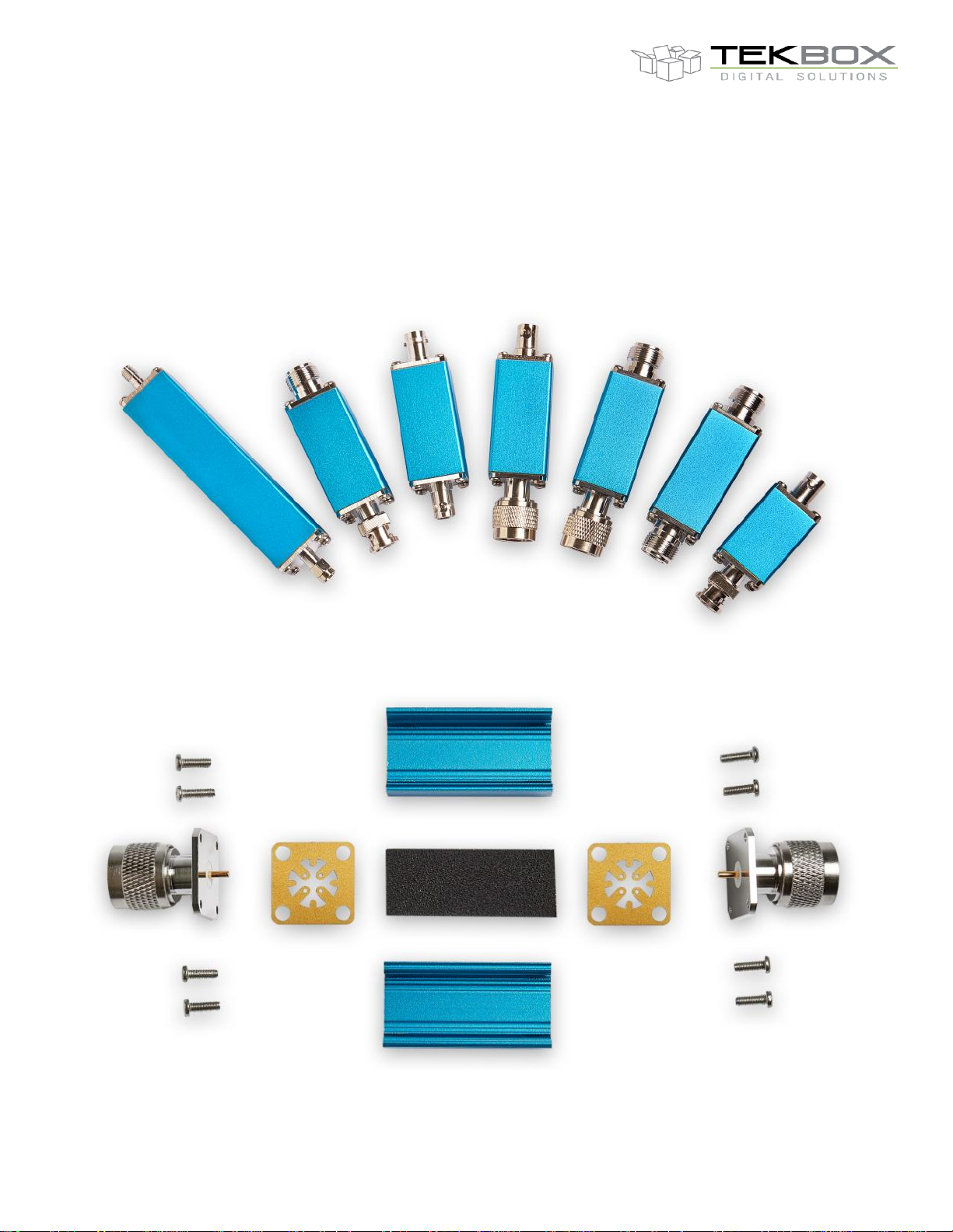
Picture 1: TBRFH1 RF housing variants
Picture 2: TBRFH1 RF housing components
Page 2
V1.0
2
Front RF connector
1 pc
Rear RF connector
1 pc
Housing half shells, aluminium
2 pcs
Screws, M3 x 10, stainless steel
8 pcs
Sheet metal ground pads
2 pcs
RF absorber foam pad
1 pc
Feed – through capacitor
optional
Flat aluminium end cap
optional
TBRFH1 SERIES
RF HOUSINGS
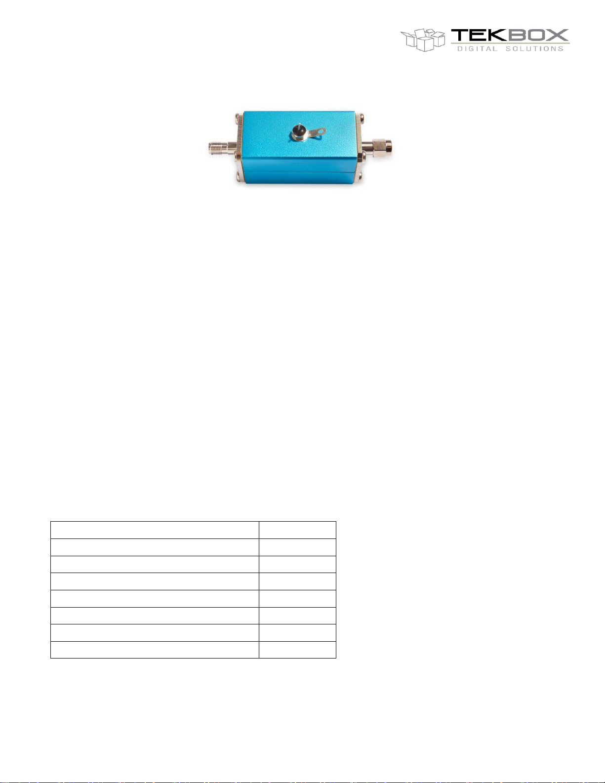
Picture 3: TBRFH1 RF housing with optional feed-through capacitor
1 Technical data
Outer cross section: 25,6 mm x 25,8 mm
Inner cross section: 20,4 mm x 20,6 mm
Housing material: anodized aluminium, exposed aluminium at front and rear side
Standard lengths: 35 mm, 50 mm, 100 mm (length of the connector not included)
Customisation of the length upon request
RF connector variants: N-Male, N-Female
BNC-Male, BNC-Female
SMA-Male, SMA-Female
any combination of the above connectors; other connectors or flat
end plates upon request
RF absorbing foam: carbon loaded, 1 GHz to 18 GHz, adhesive backing
3.2 mm thickness: - 8dB loss @ 10 GHz
6.4 mm thickness: - 21,5 dB loss @ 10 GHz
Feed-through capacitor: 10nF / 50V; default cantered placement, optional
2 Parts list
Page 3
V1.0
3
TBRFH1 SERIES
3 Mechanical drawings
RF HOUSINGS
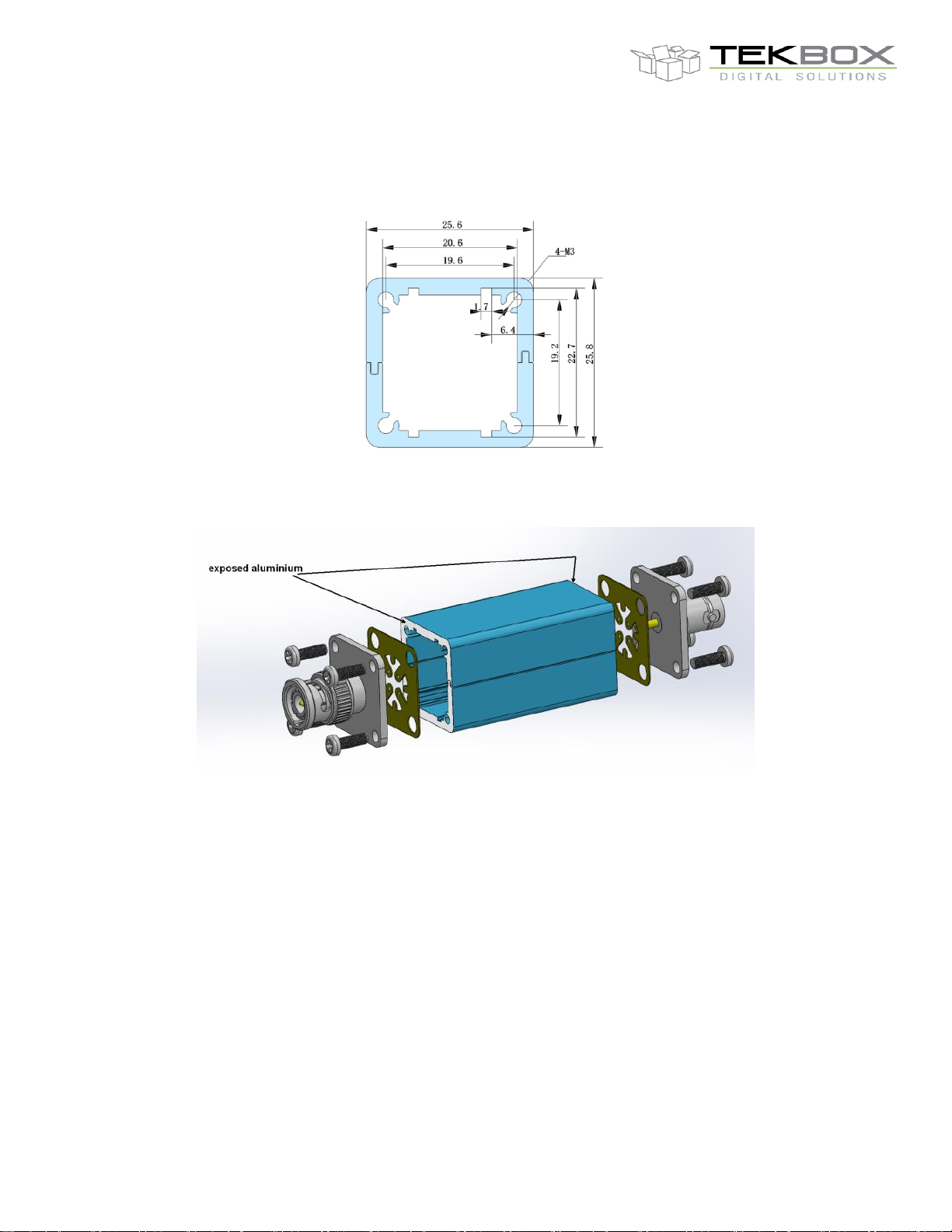
Picture 4: housing cross section
Picture 5: explosion drawing
4 Application hints
Provide exposed ground copper on your PCB to solder it to the ground connection pads.
Always solder the centre pins of the RF connectors first. Bend the wings of the ground
connection pads to reach the exposed ground copper of the PCB.
The PCB can either be inserted horizontally or diagonally, depending on the space
requirement of your circuit.
Don´t overturn the screws in order to avoid damaging the threads of the aluminium profile.
Ensure that the screws are sitting correctly, before tightening it. In case of a damaged thread,
repair it by applying a thin line of epoxy onto the affected thread.
Page 4

V1.0
4
TBRFH1 SERIES
RF HOUSINGS
5 Customization
Contact us, if you need customized housings. Following details can be customized,
depending on ordering volume:
Housing length
Other types of RF connectors, flat end plates
Position and number of feed-through capacitors
Laser engraving
Anodizing colour
6 Ordering Information
Part Numbers: TBRFH1-LL-FFFF-RRRR-A-F
LL: housing profile length
35 35 mm
50 50 mm
100 100 mm
FFFF: front RF connector type
NM N-Male
NF N-Female
SMAM SMA-Male
SMAF SMA-Female
BNCM BNC-Male
BNCF BNC-Female
RRRR: rear RF connector type
NM N-Male
NF N-Female
SMAM SMA-Male
SMAF SMA-Female
BNCM BNC-Male
BNCF BNC-Female
A: RF absorber sheet thickness
3 3.2 mm
6 6.4 mm
F: feed through capacitor
0 without feed-through capacitor
1 with feed-through capacitor
Page 5

V1.0
5
Version
Date
Author
Changes
V 1.0
11.12.2019
Mayerhofer
Creation of the document
TBRFH1 SERIES
7 History
RF HOUSINGS
 Loading...