

Page 1
V1.0
1
TBOH02
Self-Powered Active Load
1 Introduction
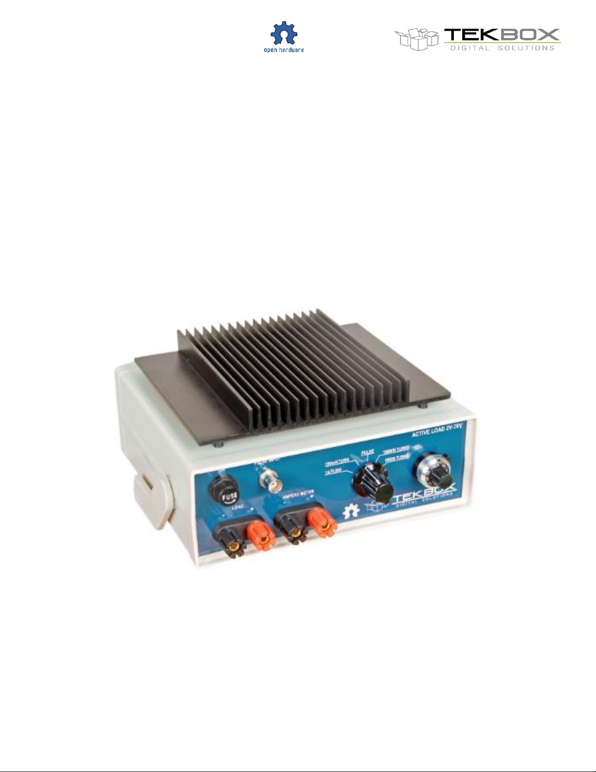
The TBOH02 is a self-powered, precision active load. It is fully analog and does not contain any clocked circuitry.
It was designed for EMC pre-compliance testing and for supply noise measurements of low and medium power
DC/DC converters. The active load can be used in EMC test set ups of DC/DC converters without adding any
emissions of its own.
The TBOH02 does not need a separate supply voltage and operates as low as 2V. Its features include constant
resistance and constant current mode. A 10 turn potentiometer with dial, a range switch and a precision reference
enable accurate setting of current or resistance. Furthermore it can be controlled by an external voltage.
As the design is fully analog, supply noise measurements using the TBOH02 as load will not be superimposed
with additional noise in contrary to such measurements carried out with digitally controlled active loads.
The TBOH02 can not only be used as active load for power supply measurements, but also as current sink or
current source for power LED testing and similar applications. It also comes handy when testing equipment in the
field, where no external power is available
The TBSOH02 operates from 2V to 70V. The maximum current is up to 10A, however it has to be taken care that
the maximum power without additional cooling is limited to 25W. A fan, attached to the heat sink, can increase the
maximum power rating up to 100W.
The design is based on the EDN, August 2005 article Precision active load operates as low as 2V by Joel Setton
By courtesy of Joel Setton, Crolles, France
Page 2
V1.0
2
TBOH02
Self-Powered Active Load
2 Parameters
Operating voltage range: 2V – 70V
Maximum current: 10A, note restriction concerning maximum continuous dissipation
Minimum current: 2,4mA (self powering current consumption)
Power rating: max. 25W continuously; with additional fan up to 100W continuously
Ranges: 0A – 1A, 0A – 10A, 1Ω - 10Ω, 10Ω - 100Ω
External voltage control input, 1A/V with the potentiometer set fully clockwise
Reference drift: 0.002%/°C
Operating temperature range: 0°C – 50°C
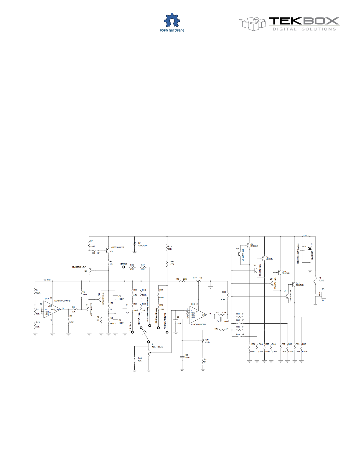
3 Schematic
Page 3

V1.0
3
C1
1uF
CAP CER 1uF 25V 10% X5R
0603
CC0603KRX5R8BB105
YAGEO
C2
10uF
CAP ALUM 10UF 100V 20%
RADIAL
UVR2A100MED
Nichicon
C3
10uF
CAP CER 10uF 16V 10% X6S
0805
C2012X6S1C106K
TDK CORPORATION
C6,C7,C8
100nF
CAP CER 0.1UF 100V 10%
X7R 0603
GRM188R72A104KA35D
Murata
D1
SMCJ54A
DIODE TVS 54V 1500W UNI
5% SMC
SMCJ54A
Littelfuse Inc
J1
TB
BARRIER TERMINAL BLOCK
2 PIN 10MM
KF-1000
Kaifeng Electronic
J2
B3B-EH-A
CONN HEADER EH TOP
3POS 2.5MM
B3B-EH-A
JST
J3
B6B-EH-A
CONN HEADER EH TOP
6POS 2.5MM
B6B-EH-A
JST
Q1,Q3,Q4
MMBT5401-7-F
TRANS PNP 150V 350MW
SMD SOT23-3
MMBT5401-7-F
DIODES INC
Q2,Q5,Q7,Q9,Q11
MMBTA06-7-F
TRANSISTOR NPN 80V
SOT23-3
TRANS NPN 100V 0.02A
Panasonic Electronic
Components
Q6,Q8,Q10,Q12
BDX34C
TRANSISTOR PNP 100V 10A
TO-220
BDX34C
ON Semiconductor
R1,R12,R33
100K
RES 100K OHM 1/10W 1%
0603
AC0603FR-07100KL
YAGEO
R2,R6,R8,R29,
R44
10K
RES 10.0K OHM 1/10W 1%
0603 SMD
RC0603FR-0710KL
YAGEO
R32
15k
RES 15K OHM 1/10W 1%
0603 SMD
RC0603FR-0715KL
YAGEO
R3
4.7K
RES 4.7K OHM 1/10W 1%
0603 SMD
RC0603FR-074K7L
YAGEO
R15,R47
68K
RES 68.0K OHM 1/10W 1%
0603 SMD
RC0603FR-0768KL
YAGEO
R5,R34
220K
RES 220K OHM 1/10W 1%
0603 SMD
RC0603FR-07220KL
YAGEO
R7
220E
RES 220 OHM 1/10W 1%
0603 SMD
RC0603FR-07220RL
YAGEO
R9
12K
RES 12.0K OHM 1/10W 1%
0603 SMD
RC0603FR-0712KL
YAGEO
R30
5.6M
RES 5.6M OHM 1/10W 5%
0603 SMD
RC0603JR-075M6L
YAGEO
R11
6.8k
RES 6.80k OHM 1/10w 1%
0603 SMD
RC0603FR-076K8L
YAGEO
R14
680k
RES 680k OHM 1/10w 1%
0603 SMD
RC0603FR-07680KL
YAGEO
R4,R16
22K
RES 22.0K OHM 1/10W 1%
0603 SMD
RC0603FR-0722KL
YAGEO
R17
1K
TRIMMER 1K OHM 0.5W PC
PIN
3362P-1-102LF
Bourns Inc.
R19
47R
RES 47.0 OHM 1/10W 1%
0603 SMD
RC0603FR-0747RL
YAGEO
R20
100R
TRIMMER 100 OHM 0.5W PC
PIN
3362P-1-101LF
Bourns Inc.
R10,R21,R22
1K
RES 1.00K OHM 1/10W 1%
0603 SMD
RC0603FR-071KL
YAGEO
R23,R25,R40,R41
10R
RES 10.0 OHM 1/10W 1%
0603 SMD
RC0603FR-0710RL
YAGEO
R26,R28,R36,R38
0.22R
RES .25 OHM 5W 5%
CERAMIC WW
CB5JBR250-ND
Stackpole Electronics Inc
R31
200R
RES 200 OHM 1/10W 1%
0603 SMD
RC0603FR-07200RL
YAGEO
TBOH02
4 BOM
Self-Powered Active Load
Page 4

V1.0
4
R35,R48
27K
RES 27K OHM 1/10W 1%
0603 SMD
RC0603FR-0727KL
YAGEO
U1
LM10CWM/NOPB
IC OPAMP GP 14SOIC
LM10CWM/NOPB
Texas Instruments
P1
3590S-2-103L
POT 10K OHM 7/8" RD WW
3590S-2-103L
Bourns Inc.
Scale Dial
2696
DIAL-7/8" 10-TURN 1/4"
SHAFT
2696
TT Electronics
2 pcs Banana
Jacks
6883
DUAL BINDING POSTS
6883
Pomona
Fuse Holder
BK/HTB-22I-R
FUSE HLDR CART 250V 10A
PNL MNT
BK/HTB-22I-R
Eaton Bussmann
Fuse
BK/ABC-10-R
FUSE CERM 10A 250VAC
125VDC 3AB
BK/ABC-10-R
Eaton Bussmann
BNC Jack
227755-1
CONN BNC JACK STR 50
OHM SOLDER
227755-1
TE Connectivity
Rotary Switch
Knob
PKES90B1/4
SWITCH KNOB FLUTED
1.01" W/SKIR
PKES90B1/4
TE Connectivity
Rotary Switch
2P5T
Rotary Switch 2Pole 5 Position
2P5T
HIWOR
Housing
08-8
Plastic Housing
08-8
Changhe Enclosures
Heatsink
YUD-168
Heatsink, L=145mm
YUD-168
TIANJIN R-SWITCH
9 pcs Crimp
Contacts
SEH-001T-P0.6
CONN TERM CRIMP EH 2230AWG mm
SEH-001T-P0.6
JST
Cable Housing
EHR-6
CONN HOUSING EH 6POS
2.5MM CRIMP
EHR-6
JST
Cable Housing
EHR-3
CONN HOUSING EH 3POS
2.5MM CRIMP
EHR-3
JST
4 pcs Thermal
Pads
173-9-230P
THERMAL PAD .009" GRAY
TO-220
173-9-230P
Wakefield Vette
PCB1
FZTBOH2M
Mainboard PCB
FZTBOH2M
Tekbox
PCB2
FZTBOH2F
Frontpanel PCB
FZTBOH2F
Tekbox
PCB3
FZTBOH2R
Rotary Switch PCB
FZTBOH2R
Tekbox
TBOH02
Self-Powered Active Load
5 Calibration
Set the rotary switch to the 100mA/turn range and set the dial of P1 to 1 turn. Then adjust R17 to 100mA load
current. Then turn P1 fully clockwise and adjust R20 to 1A load current. Repeat this two adjustments in sequence,
because they interact slightly.
Page 5
V1.0
5
TBOH02
Self-Powered Active Load
6 Voltage control
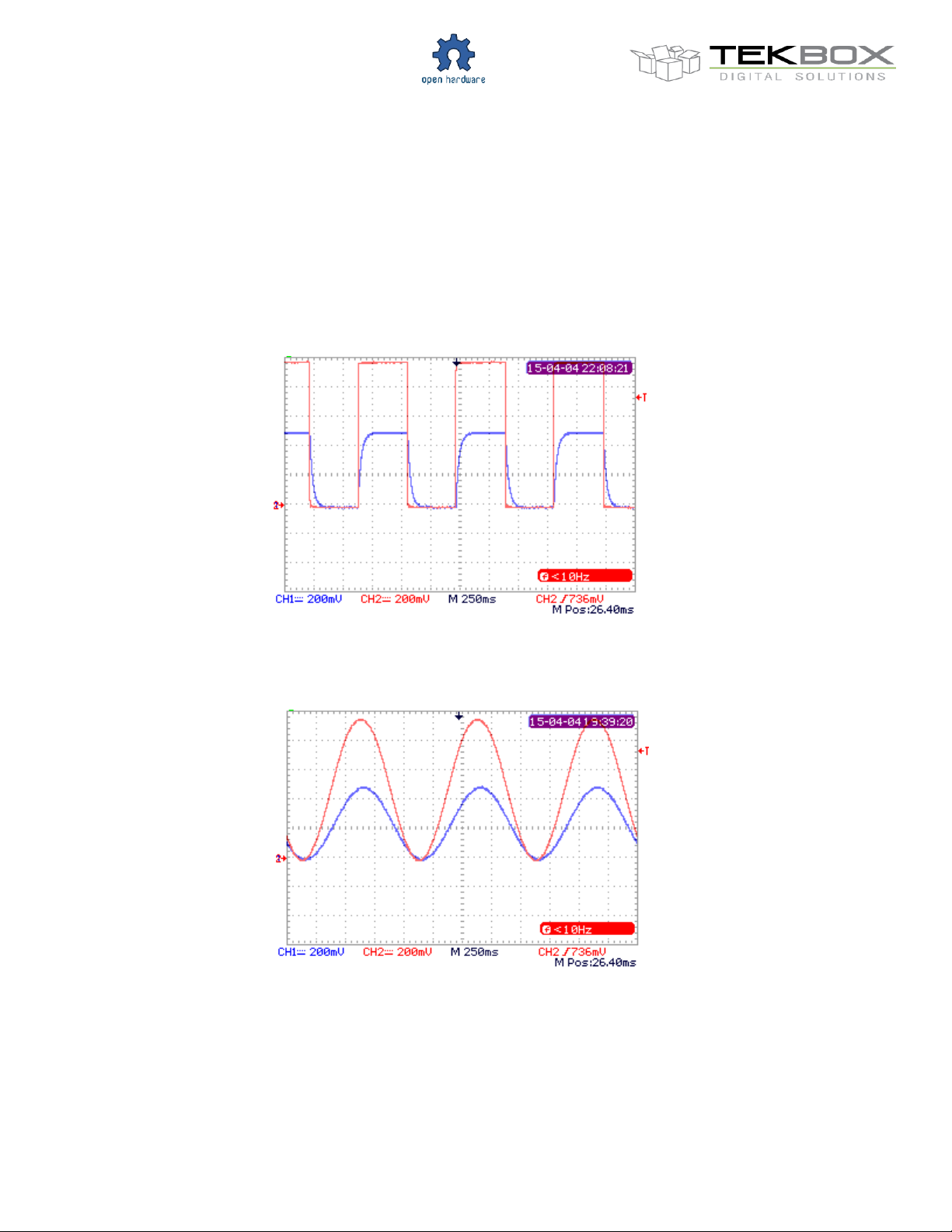
Set the rotary switch into V.C. position. With the multi-turn potentiometer set fully clockwise, 1V at the external
voltage control input translates into a load current of 1A. Similarly, setting the multi turn potentiometer into 500mA
position (5 turns) would result in 500mA/V.
Square control signal; P1 set to 500mA/V; red: signal at V.C. input; blue: load current, 1mA/mV
Sinusodial control signal; P1 set to 500mA/V; red: signal at V.C. input; blue: load current, 1mA/mV
If a higher slew rate of the load current is required, the value of C3 can be reduced.
Page 6
V1.0
6
TBOH02
Self-Powered Active Load
7 Current / power rating
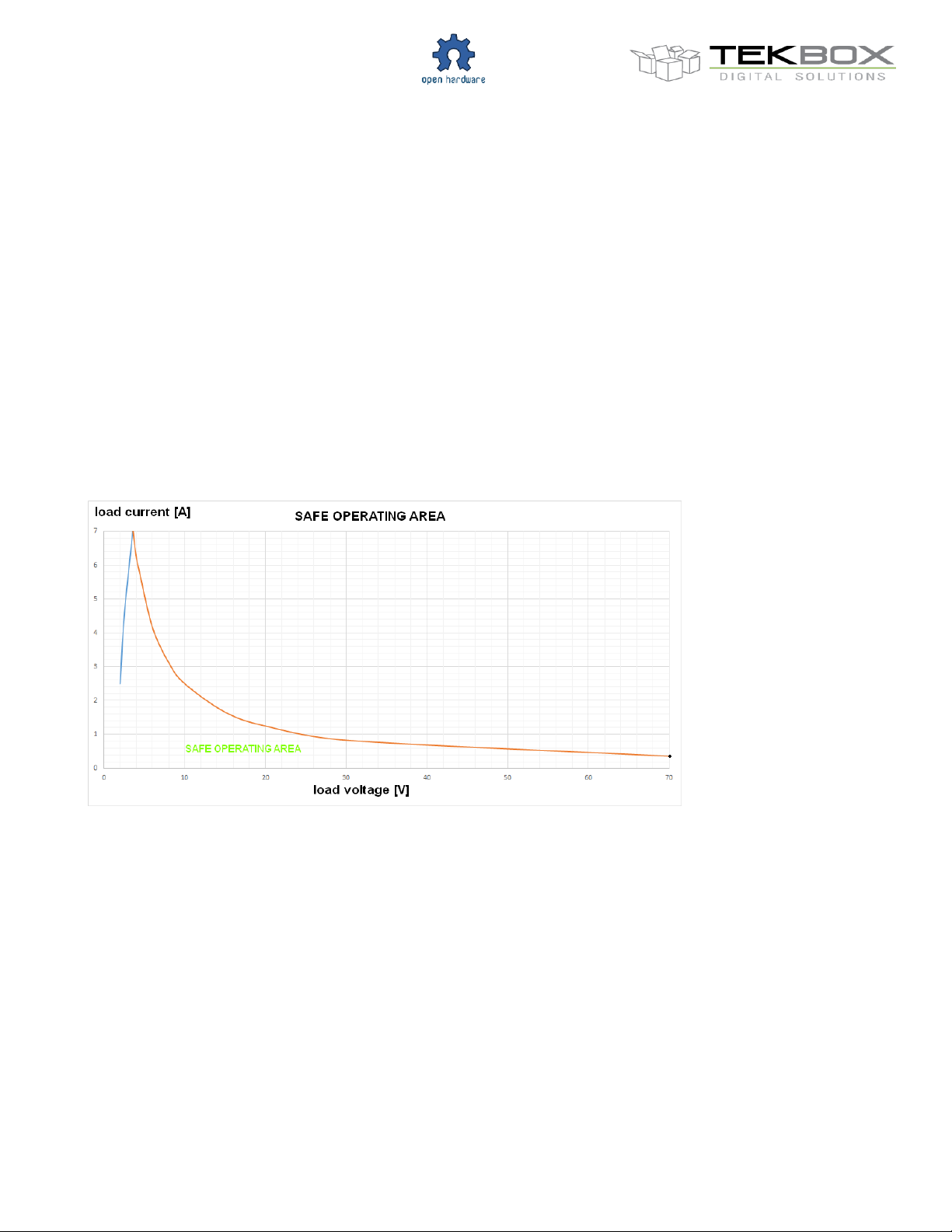
The maximum current rating of the active load is 10A. It has to be taken into account however that the continuous
power without additional cooling shall not exceed 25W at room temperature. Furthermore, due to the relation of
collector current and collector-emitter voltage, the maximum current at low voltages is limited:
Maximum current at 2V: 2,5A
Maximum current at 2,5V: 4,5A
The load voltage should be > 4V for load currents of 10A
Safe operating area at room temperature, without additional cooling:
Page 7
V1.0
7
Version
Date
Author
Changes
V1.0
05.09.2014
L.D.HIEU
Creation of the document
TBOH02
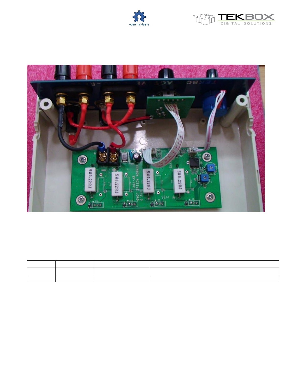
8 Assembly
Self-Powered Active Load
9 History
Table 1 – History
 Loading...