

Page 1
V1.7
TBOH01
TBOH01 5µH LISN MANUAL
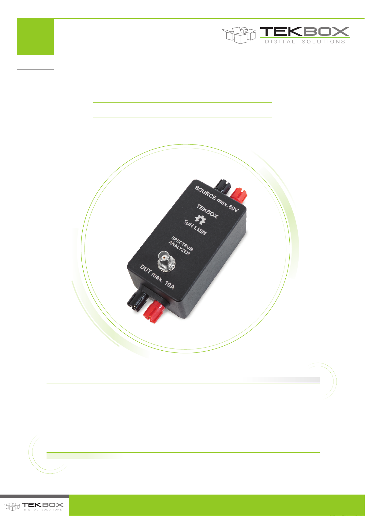
The TBOH01 5µH LISN is a device required to setup conducted noise mesurements of DC-powered
devices. It is designed to be used for EMC pre-testing in the frequency range of 150kHz to 110 MHz
according to the CISPR-25 standard, ISO 7637-2, ISO11452-2/4/5 and with limitations DO-160/ED-14G.
The LISN is inserted into the supply line of the DUT (Device Under Test). Conducted noise which is
present at the supply terminals of the DUT can be measured at the BNC connector using a spectrum
analyzer or a measurement receiver. The source (supply) terminal and the DUT terminal are decoupled
by a 5µH inductor.
© 2017 TEKBOX DIGITAL SOLUTIONS
50/11 TRUONG SON, TAN BINH DISTRICT, HO CHI MINH CITY | TEL +84 (83)5471340 | E-MAIL [email protected] | www.tekbox.net
Page 2

V1.7
TBOH01
CONTENTS
TBOH01 5 µ H LISN MANUAL
1 INTRODUCTION 2
1.1 PARAMETERS 2
1.2 SCHEMATIC 2
1.3 IMPEDANCE 3
1.4 FREQUENCY RESPONSE 4
1.5 CALIBRATION DATA ACCORDING
TO CISPR 16 -1-2 ANNEX A8 7
2 APPLICATION 9
2.1 STANDARD SETUP 9
2.2 SETUP FOR MEASURING POWER SUPPLY NOISE
SPECTRUM OF POWER SUPPLIES 10
2.3 SETUP FOR RF IMMUNITY TESTING 10
3 CISPR 25 LIMITS FOR BROADBAND CONDUCTED
EMISSIONS ON POWER INPUT TERMINALS 11
4 MEASUREMENT EXAMPLES 11
5 HISTORY 12
TABLES
Table 1 – Insertion loss measured between DUT and BNC terminal; Source terminals open/shorted 6
Table 2 - TBOH01 LISN calibration data 8
Tables 3,4 – Tables 2,3 are just a simplified excerpt. Refer to the standard for further details 11
Table 5 – History 12
PICTURES
Picture 1 – 300kHz…100MHz, measured impedance of the 5µH LISN 3
Picture 2 – 0,3…3MHz, insertion loss measured between DUT terminals and BNC connector; source terminals shorted 4
Picture 3 – 0,3…100MHz, insertion loss measured between DUT terminals and BNC connector; source terminals shorted 4
Picture 4 – 0 ,3…1GHz, insertion loss measured between DUT terminals and BNC connector; source terminals shorted 5
Picture 5 – 0,3…100MHz, isolation measured between DUT and source terminals; BNC connector terminated with 50Ω 5
Picture 6 – Calibration set up according to CISPR 16-1-2 Annex A.8 7
Picture 7 – Basic functionality of a LISN 9
Picture 8 – Example setup for a conducted noise measurement of a DC powered device 9
Picture 9 – Setup for measuring power supply noise spectrum 10
Picture 10 – Setup for RF injection 10
Picture 11 – Simple laboratory set up 11
Picture 12 – conducted emissions, frequency range 150kHz to 108MHz 12
Picture 13 – Example: conducted emissions, pre-compliance measurement of an automotive LED driver using two LISNs 12
© 2017 TEKBOX DIGITAL SOLUTIONS
50/11 TRUONG SON, TAN BINH DISTRICT, HO CHI MINH CITY | TEL +84 (83)5471340 | E-MAIL of[email protected] | www.tekbox.net
1
Page 3
1. INTRODUCTION
The TBOH01 5µH LISN is a device required to setup conducted noise
measurements of DC-powered devices. It is designed to be used
for EMC pre-testing in the frequency range of 150kHz to 110 MHz
according to the CISPR-25 standard, ISO 7637-2, ISO11452-2/4/5
and with limitations DO-160/ED-14G.
The LISN is inserted into the supply line of the DUT (Device Under
Test). Conducted noise which is present at the supply terminals of
the DUT can be measured at the BNC connector using a spectrum
analyzer or a measurement receiver. The source (supply) terminal
and the DUT terminal are decoupled by a 5µH inductor.
1.1. PARAMETERS
Frequency range: 100kHz – 110MHz (1GHz,
see figure 4)
DC Resistance: 40 mΩ
Maximum current: 10A
Nominal operating voltage range: 0 – 75V DC;
Absolute maximum rating: 200V
Built in surge protection
Terminals suitable to clamp external source
capacitors
TBOH01 5 µ H LISN MANUAL
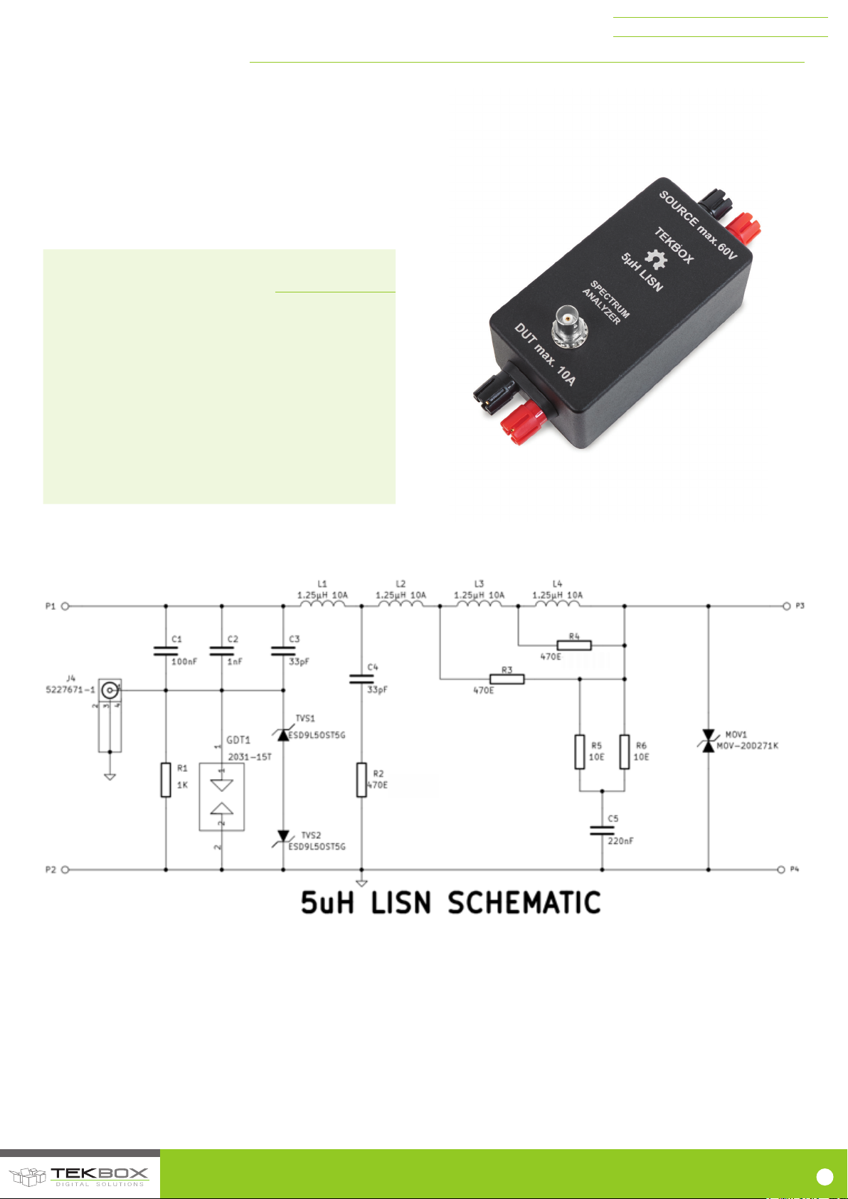
1.2 SCHEMATIC
© 2017 TEKBOX DIGITAL SOLUTIONS
50/11 TRUONG SON, TAN BINH DISTRICT, HO CHI MINH CITY | TEL +84 (83)5471340 | E-MAIL of[email protected] | www.tekbox.net
2
Page 4
0
15
30
45
60
0110
100
TBOH01 5 µ H LISN MANUAL
P1: DUT+; P3: SOURCE+; CON1: SPECTRUM ANALYZER / MEASUREMENT RECEIVER
BOM:
C1 C3216X7R2E104K 100nF 250V X7R 1206 TDK Corporation Digikey
C2 1206PC102KAT1A 1nF 250V X7R 1206 AVX Digikey
C3, C4 501R18N330JV4E 33pF 500V NP0 1206 Johanson Digikey
C5 C3225X7R2E224M 220nF 250V X7R 1210 TDK Corporation Digikey
CON1 DOSIN-801-0034 BNC 50Ω 180° PCB mount Dosin Dosin
GDT1 2031-15T-SM-RPLF GAS TUBE 60V 1KA Bourns Inc. Digikey
HOUSING 1550DBK or 1550D BOX ALUM 4.51X2.52X2.17” Hammond Digikey
L1, L2, L3, L4 1.25µH; 8 turns, ∅17mm ∅1,4mm enamelled copper wire
MOV1 MOV-20D271K VARISTOR 270V 20MM Bourns Inc. Digikey
P1, P2, P3, P4 Banana Jacks
PCB 5µH LISN V1.0 double sided, 95x58x1.6mm FZ-Electronics FZ
R1 RC1206FR-071KL RES 1K OHM 1/4W 1% 1206 Yageo Digikey
R2 RC1206FR-07470RL RES 470 OHM 1/4W 1% 1206 Yageo Digikey
R3, R4 4-1622820-8 RES 470 OHM 1W 5% 2512 TE Connectivity Digikey
R5, R6 1622820-4 RES 10 OHM 1W 5% 2512 TE Connectivity Digikey
TVS1, TVS2 ESD9L5.0ST5G TVS ULT LOW CAP SOD-923 ON-Semiconductor Digikey
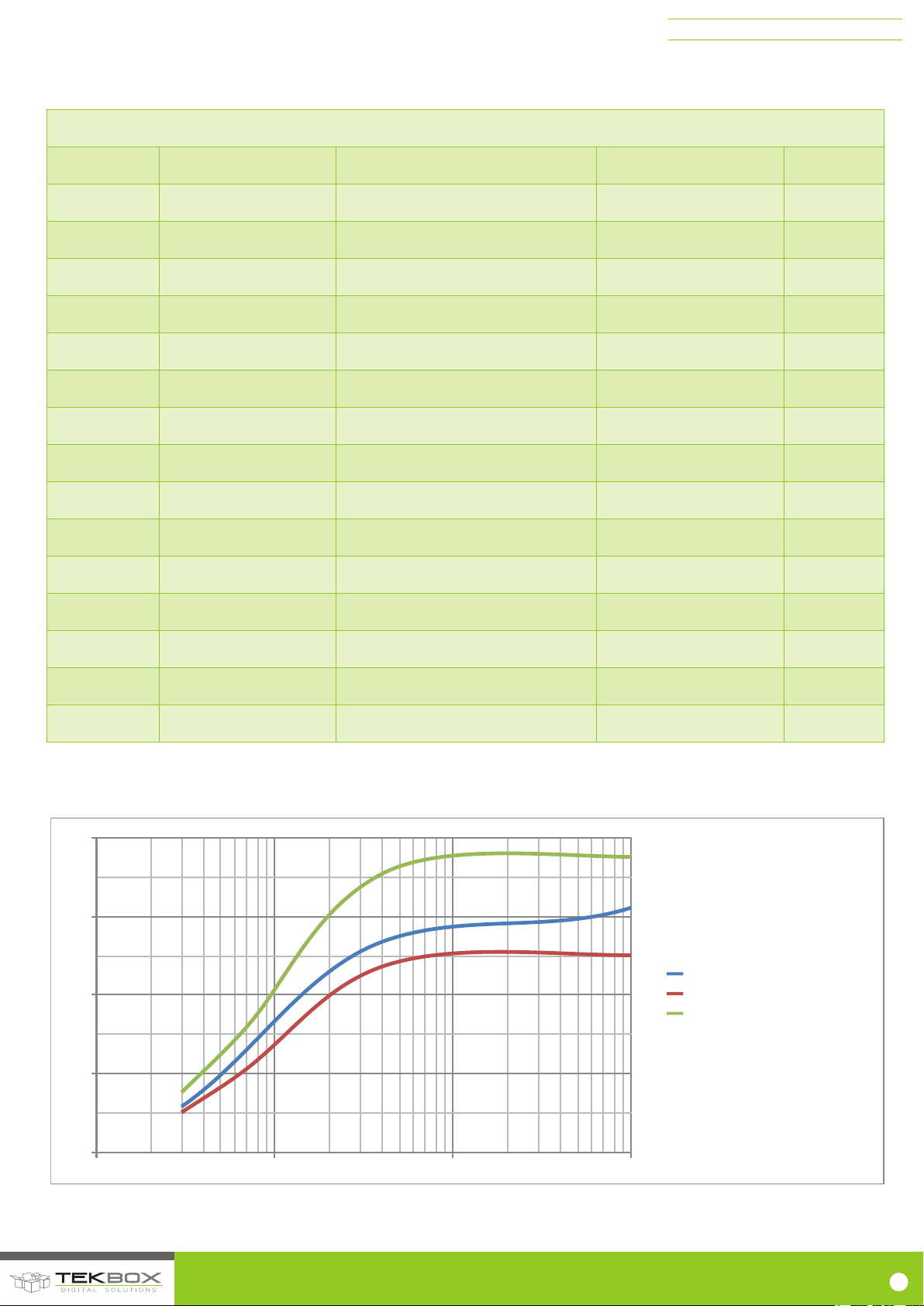
1.3. IMPEDANCE
Picture 1 – 300kHz…100MHz, measured impedance of the 5µH LISN
© 2017 TEKBOX DIGITAL SOLUTIONS
50/11 TRUONG SON, TAN BINH DISTRICT, HO CHI MINH CITY | TEL +84 (83)5471340 | E-MAIL of[email protected] | www.tekbox.net
5µH LISN Impedance
CISPR-25 Lower Limit
CISPR-25 Upper Limit
3
Page 5
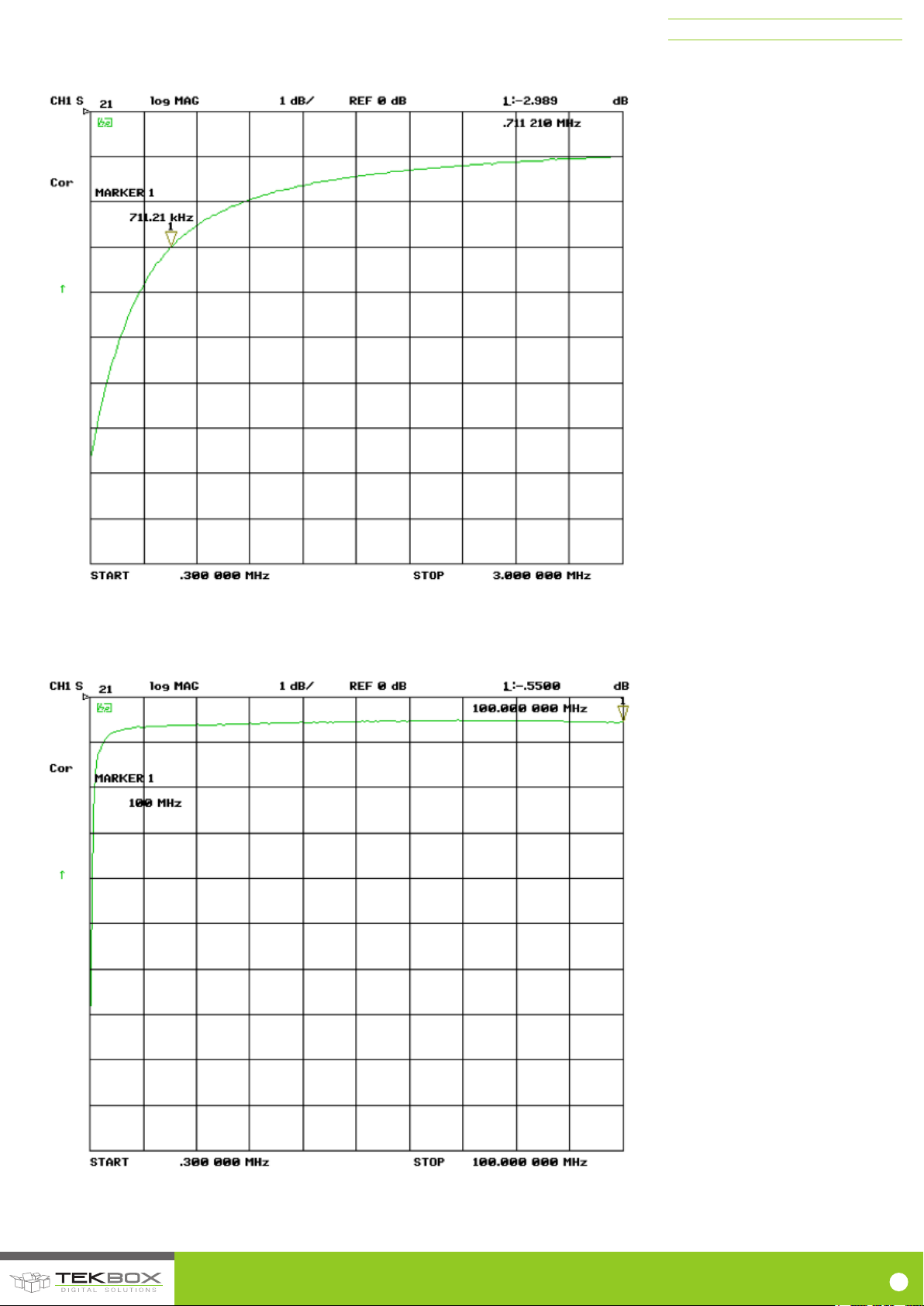
1.4. FREQUENCY RESPONSE
TBOH01 5 µ H LISN MANUAL
Picture 2 – 0,3…3MHz, insertion loss measured between DUT terminals and BNC connector;
source terminals shorted
Picture 3 – 0,3…100MHz, insertion loss measured between DUT terminals and BNC
connector; source terminals shorted
© 2017 TEKBOX DIGITAL SOLUTIONS
50/11 TRUONG SON, TAN BINH DISTRICT, HO CHI MINH CITY | TEL +84 (83)5471340 | E-MAIL of[email protected] | www.tekbox.net
4
Page 6
TBOH01 5 µ H LISN MANUAL
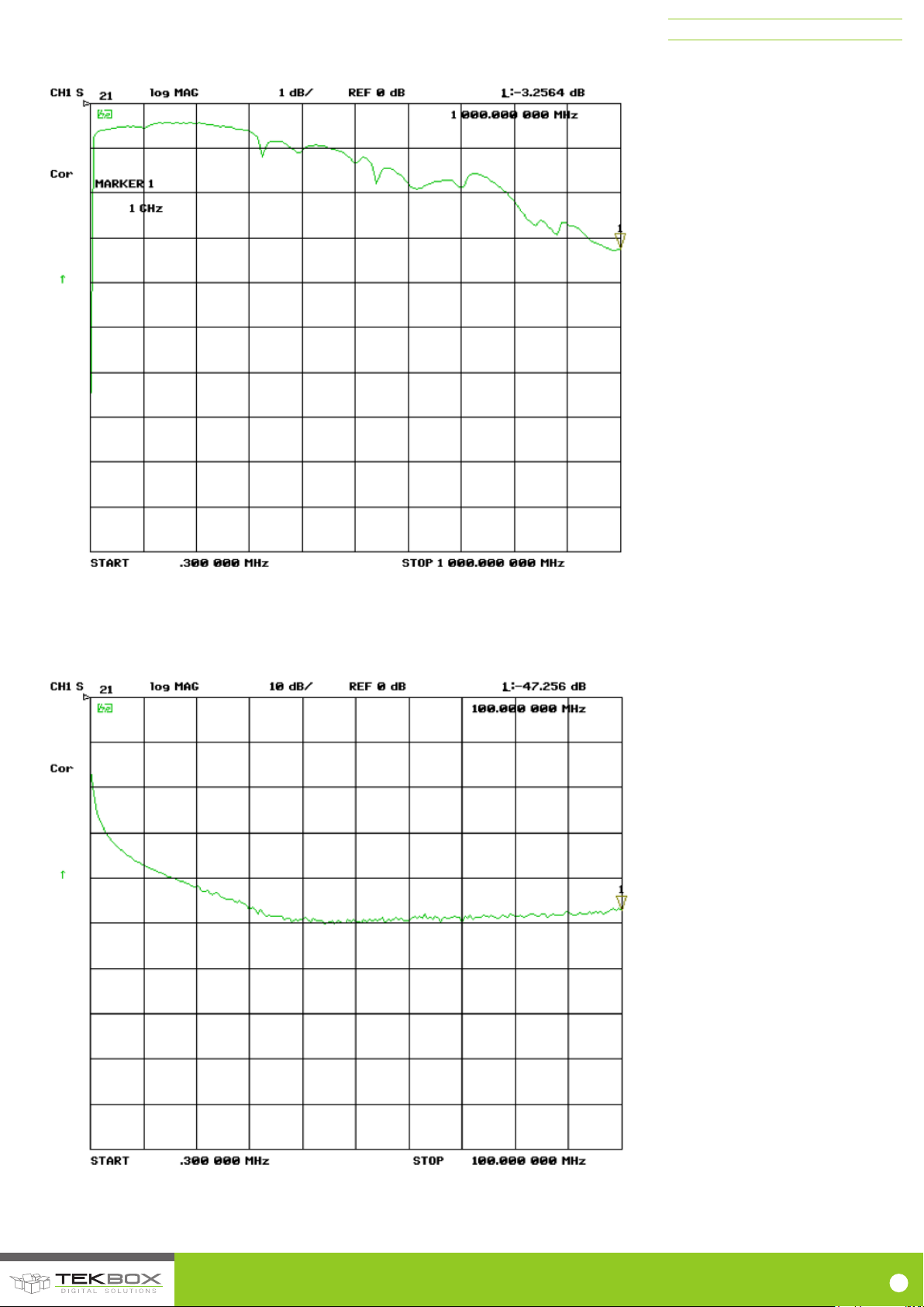
Picture 4 –0 ,3…1GHz, insertion loss measured between DUT terminals and BNC connector;
source terminals shorted
Picture 5 – 0,3…100MHz, isolation measured between DUT and source terminals; BNC
connector terminated with 50Ω
© 2017 TEKBOX DIGITAL SOLUTIONS
50/11 TRUONG SON, TAN BINH DISTRICT, HO CHI MINH CITY | TEL +84 (83)5471340 | E-MAIL of[email protected] | www.tekbox.net
5
Page 7

TBOH01 5 µ H LISN MANUAL
Frequency
Max. insertion loss (DUT terminals to
BNC; source terminals open)
Max. insertion loss (DUT terminals to
BNC; source terminals shorted)
150 kHz -16.3 dB -12.7 dB
200 kHz -13.5 dB -10.3 dB
250 kHz -11.1 dB -8.5 dB
300 kHz -9 dB -7.2 dB
350 kHz -7.8 dB -6.1 dB
400 kHz -6.7 dB -5.3 dB
450 kHz -5.9 dB -4.7 dB
500 kHz -5.1 dB -3.9 dB
600 kHz -4.2 dB -3.4 dB
700 kHz -3.5 dB -3 dB
800 kHz -3 dB -2.5 dB
900 kHz -2.7 dB -2.3 dB
1 MHz -2.5 dB -2.1 dB
5 MHz -1.2 dB -1.2 dB
10 MHz -0.7 dB -0.7 dB
50 MHz -0.8 dB -0.8 dB
100 MHz -1 dB -1 dB
150 MHz -1.2 dB -1.2 dB
250 MHz -1.9 dB -1.9 dB
Table 1, insertion loss measured between DUT and BNC terminal; Source terminals open/shorted
SOURCE CAPACITORS:
CISPR 25 and ISO 11452-2/4/5 specify a 1µF capacitor to be connected in parallel to the source terminals. The TBOH01 terminals have perpendicular
holes to easily insert and clamp the pins of the external capacitor. DO-160 specifies a 10µF capacitor in parallel to the source terminals. However,
consider that the TBOH01 is not specified for the full DO-160 frequency range. Use the correction table column “source terminals shorted” for these
applications. ISO7637-2 does not specify an external capacitor. Use the correction table column “source terminal open” then.
© 2017 TEKBOX DIGITAL SOLUTIONS
50/11 TRUONG SON, TAN BINH DISTRICT, HO CHI MINH CITY | TEL +84 (83)5471340 | E-MAIL of[email protected] | www.tekbox.net
6
Page 8
1.5. CALIBRATION DATA ACCORDING TO CISPR 16 -1-2 ANNEX A8
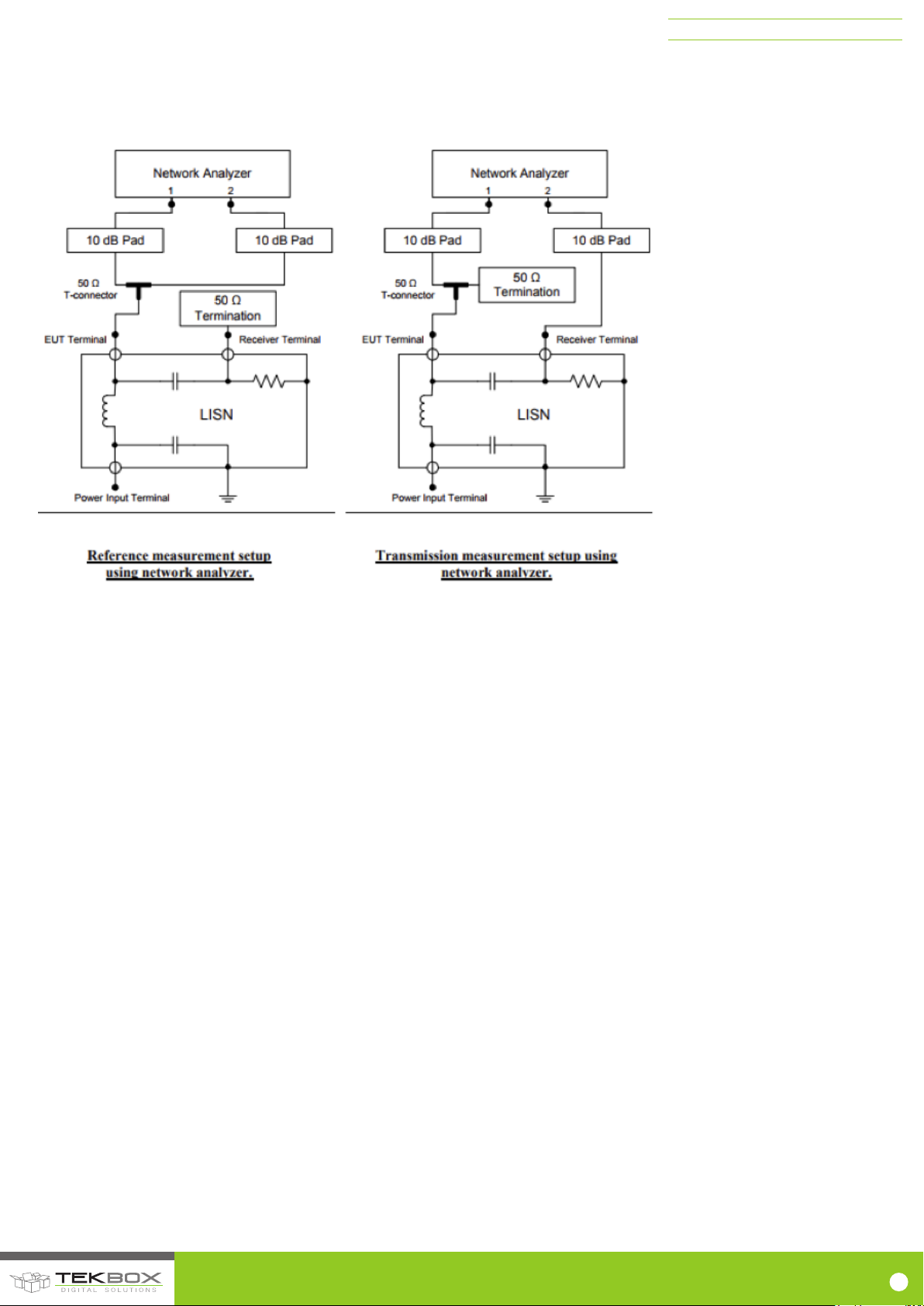
Calibration set up according to CISPR 16-1-2 Annex A.8.
TBOH01 5 µ H LISN MANUAL
Picture 6 – Calibration set up according to CISPR 16-1-2 Annex A.8.
© 2017 TEKBOX DIGITAL SOLUTIONS
50/11 TRUONG SON, TAN BINH DISTRICT, HO CHI MINH CITY | TEL +84 (83)5471340 | E-MAIL of[email protected] | www.tekbox.net
7
Page 9

TBOH01 5 µ H LISN MANUAL
Frequency
[MHz]
Insertion loss CISPR-25 and
ISO1145-2/4/5
(1µF across source terminals) [dB]
Insertion loss DO-160
(10µF across source terminals) [dB]
Insertion loss ISO7637-2
(no capacitor across source
terminals] [dB]
0.03 -3.9 -3.6 -3.53
0.05 -1.8 -1.77 -1.7
0.1 -0.6 -0.53 -0.56
0.5 -0.1 -0.09 -0.08
1 -0.1 -0.19 -0.17
10 -0.15 -0.16 -0.13
20 -0.25 -0.26 -0.25
30 -0.42 -0.44 -0.43
40 -0.61 -0.63 -0.62
50 -0.84 -0.85 -0.85
60 -1.07 -1.09 -1.07
70 -1.3 -1.33 -1.3
80 -1.56 -1.58 -1.57
90 -1.86 -1.88 -1.86
100 -2.15 -2.2 -2.19
110 -2.33 -2.37 -2.35
120 -2.55 -2.6 -2.57
130 -2.73 -2.79 -2.74
140 -2.91 -3.05 -3
150 -3.1 -3.17 -3.12
160 -3.3 -3.37 -3.34
170 -3.5 -3.59 -3.55
180 -3.71 -3.79 -3.77
190 -3.9 -3.95 -3.92
200 -4.05 -4.13 -4.07
Table 2, TBOH01 LISN calibration data
© 2017 TEKBOX DIGITAL SOLUTIONS
50/11 TRUONG SON, TAN BINH DISTRICT, HO CHI MINH CITY | TEL +84 (83)5471340 | E-MAIL of[email protected] | www.tekbox.net
8
Page 10
2. APPLICATION
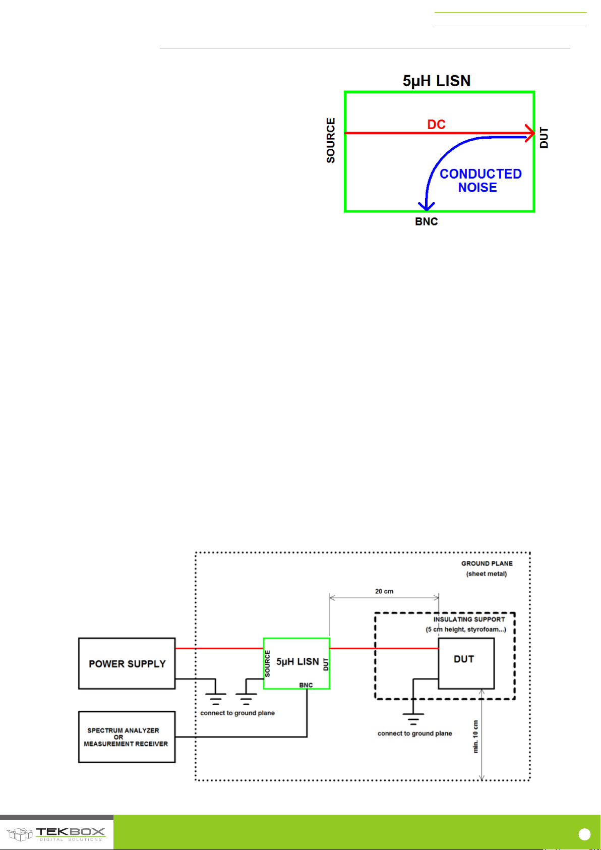
A Line Impedance Stabilisation Network basically is a coupling device to
measure conducted noise present on supply lines with a measurement
receiver or spectrum analyzer. It establishes a defined impedance
setup for the measurement, independent of the impedance of the power
source. Hence the name Line Impedance Stabilisation Network.
A LISN has three terminals – both ends of a feedthrough path for DC
and a 50 Ω coaxial terminal to connect a measurement receiver or
spectrum analyzer.
Conducted noise from the Device Under Test (DUT) is coupled from the
supply line to a 50 Ω BNC terminal.
Coupling loss from the DUT connector to the BNC connector is less than
1 dB from 3 MHz to 100 MHz. On the other hand, the LISN isolates the
DUT and BNC terminals from conducted noise coming from the source
side (Figure 5).
TBOH01 5 µ H LISN MANUAL
The DUT can be any DC powered electronic device. The Source can be
any DC power supply up to 200V max.
Though the LISN is normally used to measure conducted noise from a
DC powered device, it ccould also be used to inject RF to the supply
lines of the DUT. This setup requires an additional 50 Ω feedthrough
terminal at the BNC connector. Furthermore the LISN could be used
to measure the noise of a source, for example a switched mode power
supply or a DC/DC converter output. In this case, the power supply has
to be connected to the DUT terminals and a load has to be connected
to the Source terminals.
The test configurations shown in the following chapters are just
examples and not strictly according to standards. They should rather
serve as an easy means to carry out EMC pre-testing in the lab, before
going to a certified test house.
Setup dimensions, Limits for spurious levels, bandwidth and detector
settings for the measurement receiver or spectrum analyzer have to be
derived from the applied standards.
2.1. STANDARD SETUP
Conducted noise measurements are typically conducted using a sheet
metal as ground plane. The GND terminals of all involved devices are
connected to the metal shield using short cables.
As the measurement will be conducted in lab, rather than in a shielded
chamber, a background noise measurement should be carried out with
the DUT switched off or disconnected in order to be able to differentiate
between conducted noise spectrum and background electric smog.
Picture 7 – basic functionality of a LISN
Standard conformant measurements would make use of two LISNs, if
the vehicle power return line of the DUT is longer than 200 mm. One
in the positive and another one in the negative supply line and then
alternatively measure the noise. For a precompliance measurement,
measuring the positive supply line gives a good indication on the
performance of the device. The measurement can then be repeated
with the LISN inserted into the negative supply line to check if the noise
levels are any different.
Professional conducted noise measurements are done in shielded
chambers, as any RF smog picked up by the wires from LISN to DUT or
by the DUT itself, will be present at the BNC terminal. Consequently, a
measurement with the DUT powered off should be done upfront in order
to distinguish between real conducted noise generated by the DUT and
RF smog from other sources (background noise).
The picture below shows a typical conducted emissions measurement
setup, such as specified in CISPR-25 standard. Setup details will differ
depending on the type of DUT and applicable standards. For example,
if the DUT has a vehicle power return line shorter than 200 mm, one
LISN is inserted into the positive supply line. If the vehicle return line
of the DUT is longer than 200 mm, two LISNs are required. One for the
positive supply line and one for the power return line.
Picture 8 – example setup for a conducted noise measurement of a DC powered device
© 2017 TEKBOX DIGITAL SOLUTIONS
50/11 TRUONG SON, TAN BINH DISTRICT, HO CHI MINH CITY | TEL +84 (83)5471340 | E-MAIL of[email protected] | www.tekbox.net
9
Page 11
TBOH01 5 µ H LISN MANUAL
2.2. SETUP FOR MEASURING POWER SUPPLY NOISE SPECTRUM OF POWER SUPPLIES
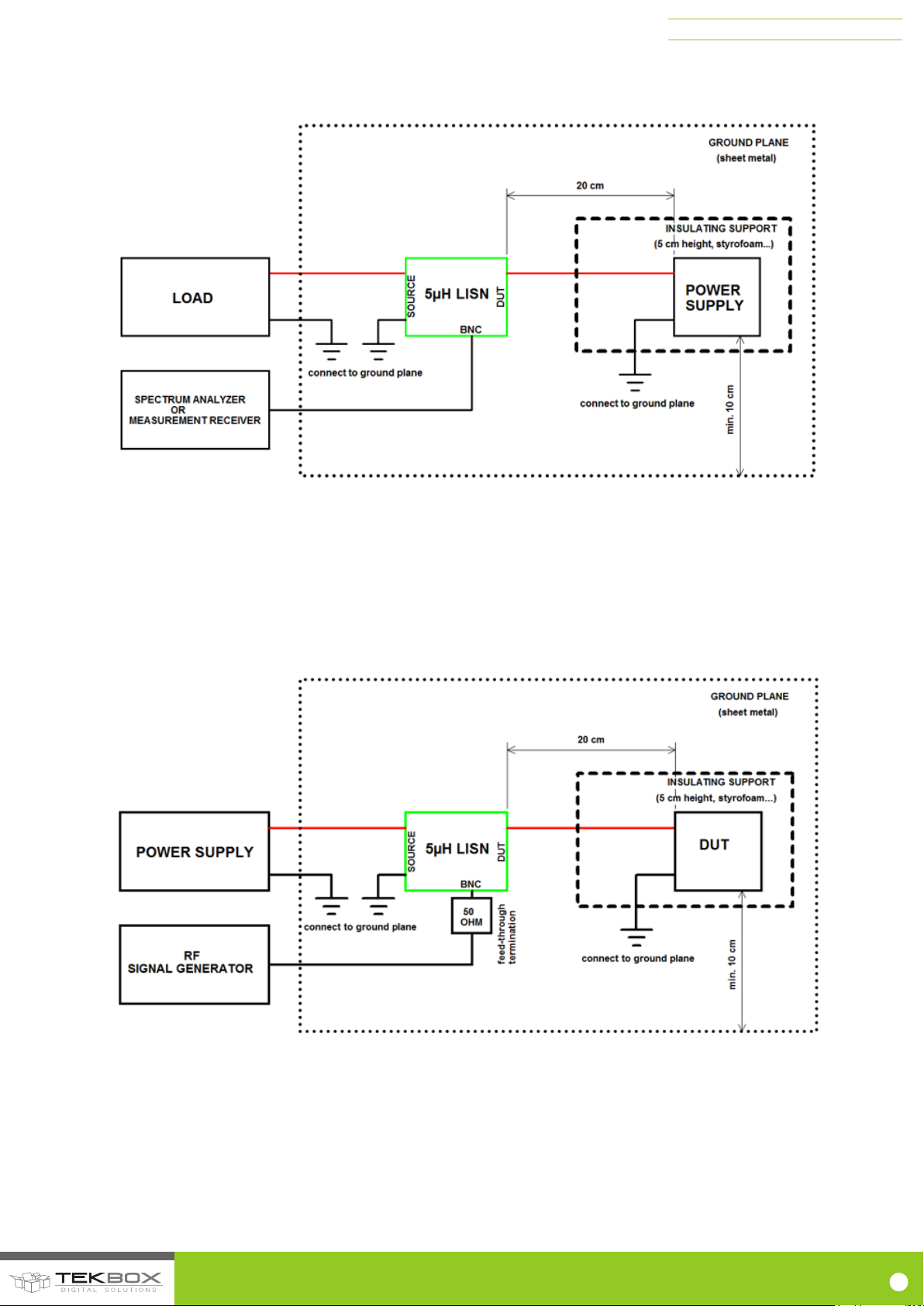
The LISN can also be used to measure noise spectrum at the output terminals of a power supply or switched mode regulator.
Picture 9 – setup for measuring power supply noise spectrum
Kindly notice again, that for exact set ups, you need to check the standards applicable to your DUT, especially CISPR 25, chapter 6.1.2 which defines
if one or two LISNs have to be used for the setup.
2.3. SETUP FOR RF IMMUNITY TESTING
By adding a 50 Ohm feed through termination, the LISN can also be utilized to inject RF into the supply line of the DUT. The power rating of the
feedthrough termination has to match the injected RF power level.
Picture 10 – setup for RF injection
© 2017 TEKBOX DIGITAL SOLUTIONS
50/11 TRUONG SON, TAN BINH DISTRICT, HO CHI MINH CITY | TEL +84 (83)5471340 | E-MAIL of[email protected] | www.tekbox.net
10
Page 12
TBOH01 5 µ H LISN MANUAL
3. CISPR 25 LIMITS FOR BROADBAND CONDUCTED EMISSIONS ON
POWER INPUT TERMINALS
Levels in dBµV
CLASS
0,15 – 0,3 MHz 0,53 – 1,8 MHz 5,9 – 6,2 MHz 30 – 54 MHz 76 – 108 MHz
Peak
Quasi
Peak
Peak
Quasi
Peak
Peak
Quasi
Peak
Peak
Quasi
Peak
Peak
1 110 97 86 73 77 64 68 55 62 49
2 100 87 78 65 71 58 62 49 56 43
3 90 77 70 57 65 52 56 43 50 37
4 80 67 62 49 59 46 50 37 44 31
5 70 57 54 41 53 40 44 31 38 25
For short duration disturbances, add 6 dB to the level shown in the table
Measuring instrument bandwidth (6 dB)
Frequency band [MHz] Broadband peak or quasi-peak Narrowband peak or average
0,15 - 30 9 kHz 9 kHz
30 – 1000 FM Broadcast
Mobile Service
120 kHz
120 kHz
120 kHz
9 kHz
Quasi
Peak
The tables 3,4 above are just a simplified excerpt. Refer to the standard for further details
4. MEASUREMENT EXAMPLES
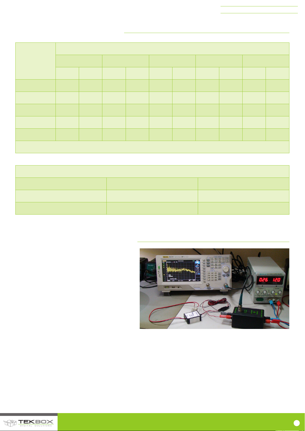
The picture to the right shows a simple set up to do a quick test
of a 9V to 24V USB car charger adapter. The charger adapter
gets supplied with 12 V at the DUT terminals of the LISN.
The power supply is connected to the Source terminals of the
LISN. A spectrum analyzer is connected to the BNC connector
of the LISN.
SPECTRUM ANALYZER SETTINGS:
Frequency: 150kHz - 3MHz
Detector Type: Positive Peak (use Max. Hold or Quasi Peak,
if available)
Filter Type: EMI
BW: 9kHz
Internal Attenuator: OFF
Units: dBµV
The setup is not CISPR25 conformant – no metal ground plane is involved. Nevertheless, the measurement permits a judgement of the conducted emission
performance of the DUT and will be very useful to determine, if modications of the circuit result in improved suppression of conducted emissions.
Picture 11 – simple laboratory set up
© 2017 TEKBOX DIGITAL SOLUTIONS
50/11 TRUONG SON, TAN BINH DISTRICT, HO CHI MINH CITY | TEL +84 (83)5471340 | E-MAIL of[email protected] | www.tekbox.net
11
Page 13
TBOH01 5 µ H LISN MANUAL
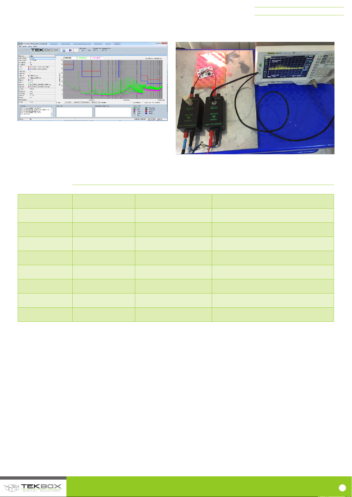
The screenshot below shows the result of a CISPR 25 conducted noise measurement of a DC/DC converter carried out with two TBOH01, a Rigol
DSA815 and the Tekbox PC SW EMCview. With reference to the CISPR 25 limits, the measurement result shows compliance with Class 5 limits.
Picture 12 – conducted emissions, frequency range 150kHz to 108MHz
Picture 13 – Example: conducted emissions, pre-compliance measurement
of an automotive LED driver using two LISNs
5. HISTORY
Version Date Author Changes
V1.0 14.09.2010 L.D.HIEU Creation of the document
V1.1 18.11.2013 L.D.HIEU Chapter 2 updated
V1.2 17.03.2014 L.D.HIEU Part number of R2 corrected
V1.3 25.11.2014 MAYERHOFERs Chapter 1.1 updated
V1.4 17.01.2016 MAYERHOFER Insertion loss table added
V1.5 8.8.2016 MAYERHOFER Picture 12 added
V1.6 24.4.2017 MAYERHOFER Updated chapters 1, 1.4, 3, 4
V1.7 13.12.2017 MAYERHOFER Chapters 1.5 added
Table 5 – History
© 2017 TEKBOX DIGITAL SOLUTIONS
50/11 TRUONG SON, TAN BINH DISTRICT, HO CHI MINH CITY | TEL +84 (83)5471340 | E-MAIL of[email protected] | www.tekbox.net
12
 Loading...