

Page 1
V1.0
TBMA6-P
Passive Loop Antenna
1
1 Introduction
The TBMA6-P is a passive Loop Antenna, expanding the Tekbox product range of affordable
EMC pre-compliance test equipment.
The loop antenna is designed for radiated emission measurements in the frequency range
9 kHz – 30 MHz, according to CISPR 16. The loop antenna has a diameter of 60 cm and
provides sufficient sensitivity to carry out all relevant measurements specified in the
corresponding CISPR standards for the frequency range 9 kHz – 30 MHz.
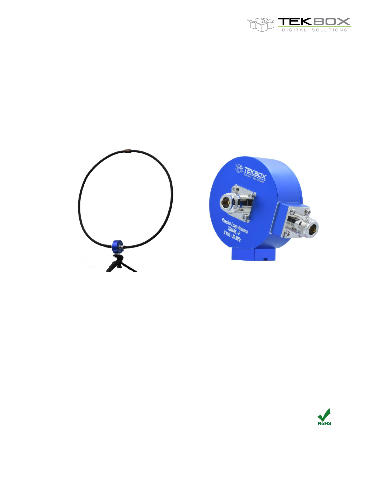
Picture 1: TBMA6-P passive loop antenna / transducer
The loop is built from corrugated coaxial cable and attached to the transducer with Nconnectors. This construction provides flexibility to use it with various loop diameters. An
attachment with a ¼” thread permits connectivity to standard tripods.
2 Specification
Characterized frequency range: 9 kHz to 30 MHz
Magnetic field antenna factor: -20 dB/Ωm @ 30 MHz, typ.
Electric field antenna factor: 31,5 dB/m @ 30 MHz, typ.
Sensitivity: -24 dBµA/m @ 30 MHz
Dimensions: Ф 60 cm
Weight: 800 g
Connector type: N female
Mount: ¼” thread
Page 2
V1.0
TBMA6-P
Passive Loop Antenna
2
3 Antenna factors
A spectrum analyzer or measurement receiver connected to the antenna will typically display
measured power in dBm or voltage in dBµV.
The antenna factor AF is an antenna and frequency dependent parameter, which is required
to convert the measured voltage into the corresponding electric or magnetic field strength.
For magnetic field strength:
H[dBµA/m] = V[dBµV] + AFH[dB/Ωm]
Where AFH is the magnetic antenna factor in [dB/Ωm] or [dBS/m]
In the far field, the free space impedance Z0 = 377 Ω links electric field strength with magnetic
field strength.
AFE[dB/m] = AFH[dB/Ωm] + Z0[dBΩ]
AFE[dB/m] = AFH[dB/Ωm] + 51.5 dBΩ
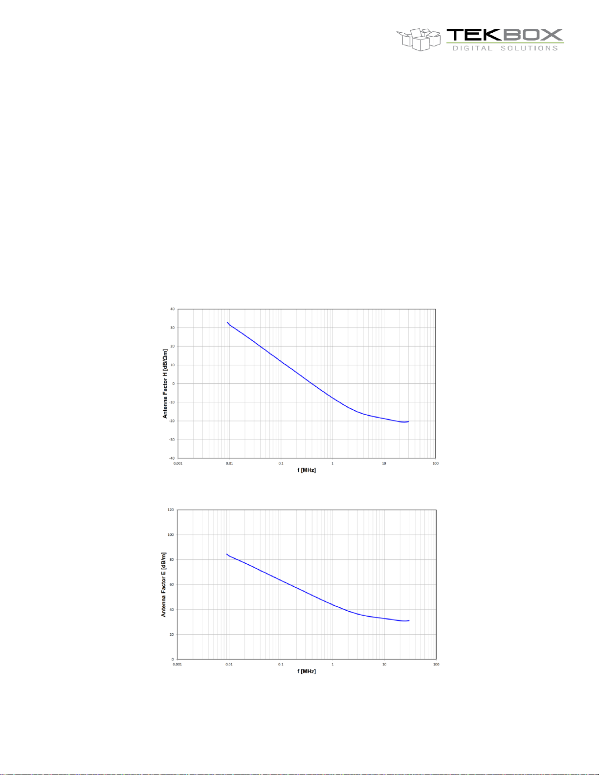
Figure 1: magnetic field antenna factor, TBMA6-P, 60 cm loop, 9 kHz – 30 MHz, typical data
Figure 2: electric field antenna factor, TBMA6-P, 60 cm loop, 9 kHz – 30 MHz, typical data
Page 3
V1.0
TBMA6-P
Passive Loop Antenna
3
4 Antenna factor table
Frequency [MHz]
Magnetic field antenna factor
[dB/Ωm]
Electric field antenna factor
[dB/m]
Uncertainty [dB]
0,009
32,934
84,454
±1,20
0,010
31,540
83,060
±1,20
0,020
25,870
77,390
±1,20
0,030
22,444
73,964
±1,20
0,040
19,803
71,323
±1,20
0,050
17,970
69,490
±1,20
0,060
16,273
67,793
±1,20
0,070
14,999
66,519
±1,20
0,080
13,928
65,448
±1,20
0,090
12,754
64,274
±1,20
0,100
11,944
63,464
±1,20
0,110
10,982
62,502
±1,20
0,120
10,297
61,817
±1,20
0,130
9,694
61,214
±1,20
0,140
8,994
60,514
±1,20
0,150
8,463
59,983
±1,20
0,200
5,956
57,476
±1,20
0,300
2,441
53,961
±1,20
0,400
-0,045
51,475
±1,20
0,500
-1,960
49,560
±1,20
0,600
-3,492
48,028
±1,20
0,700
-4,772
46,748
±1,20
0,800
-5,882
45,638
±1,20
0,900
-6,825
44,695
±1,20
1,000
-7,681
43,839
±1,20
2,000
-12,731
38,789
±1,20
3,000
-15,043
36,477
±1,20
4,000
-16,287
35,233
±1,20
5,000
-17,039
34,481
±1,20
6,000
-17,525
33,995
±1,20
7,000
-17,898
33,622
±1,20
8,000
-18,215
33,305
±1,20
9,000
-18,488
33,032
±1,20
10,000
-18,736
32,784
±1,20
11,000
-18,967
32,553
±1,20
12,000
-19,179
32,341
±1,20
13,000
-19,376
32,144
±1,20
14,000
-19,560
31,960
±1,20
15,000
-19,734
31,786
±1,20
16,000
-19,890
31,630
±1,20
17,000
-20,037
31,483
±1,20
18,000
-20,173
31,347
±1,20
19,000
-20,296
31,224
±1,20
20,000
-20,398
31,122
±1,20
21,000
-20,482
31,038
±1,20
22,000
-20,549
30,971
±1,20
23,000
-20,592
30,928
±1,20
24,000
-20,613
30,907
±1,20
25,000
-20,626
30,894
±1,20
26,000
-20,591
30,929
±1,20
27,000
-20,555
30,965
±1,20
28,000
-20,494
31,026
±1,20
29,000
-20,423
31,097
±1,20
30,000
-20,334
31,186
±1,20
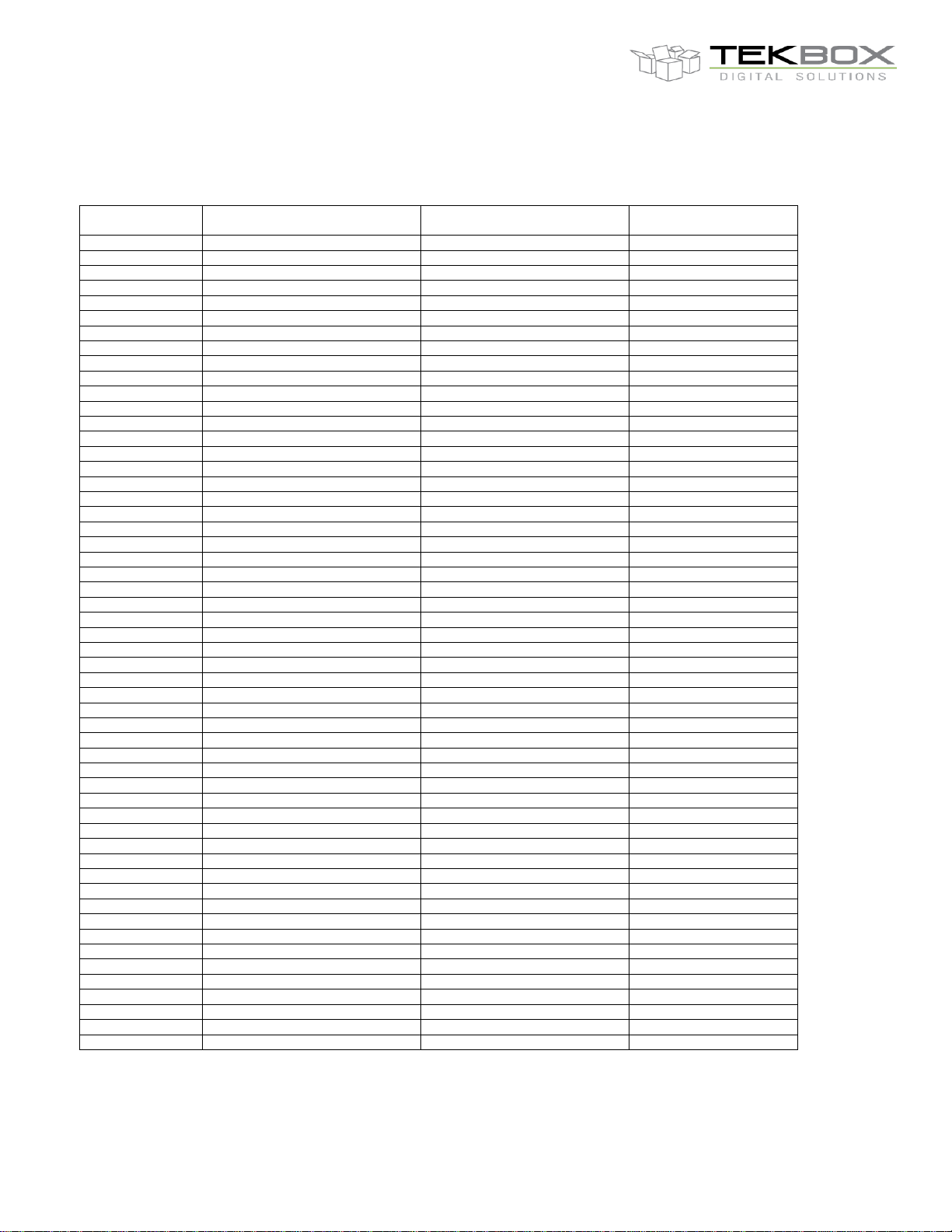
Table 1: TBMA6-P, 60cm loop, antenna factors, 9 kHz – 30 MHz, typical values
Page 4
V1.0
TBMA6-P
Passive Loop Antenna
4
The antenna factors of the 60 cm loop can be used to estimate the antenna factors of loop
antennas with different diameter.
Loop diameter
AF
1 m
+4.5 dB
60 cm
0 dB
30 cm
-6 dB
25 cm
-8 dB
Table 2: antenna factor conversion for different loop diameters
5 Sensitivity
The sensitivity of a radiated noise measurement set up looks at the base noise of the
available spectrum analyzer or measurement receiver. Applying the antenna factor gives the
resulting noise floor with respect to the magnetic field. According to CISPR 16, this noise floor
has to be at least 6 dB below the emission limits of the applied standard.
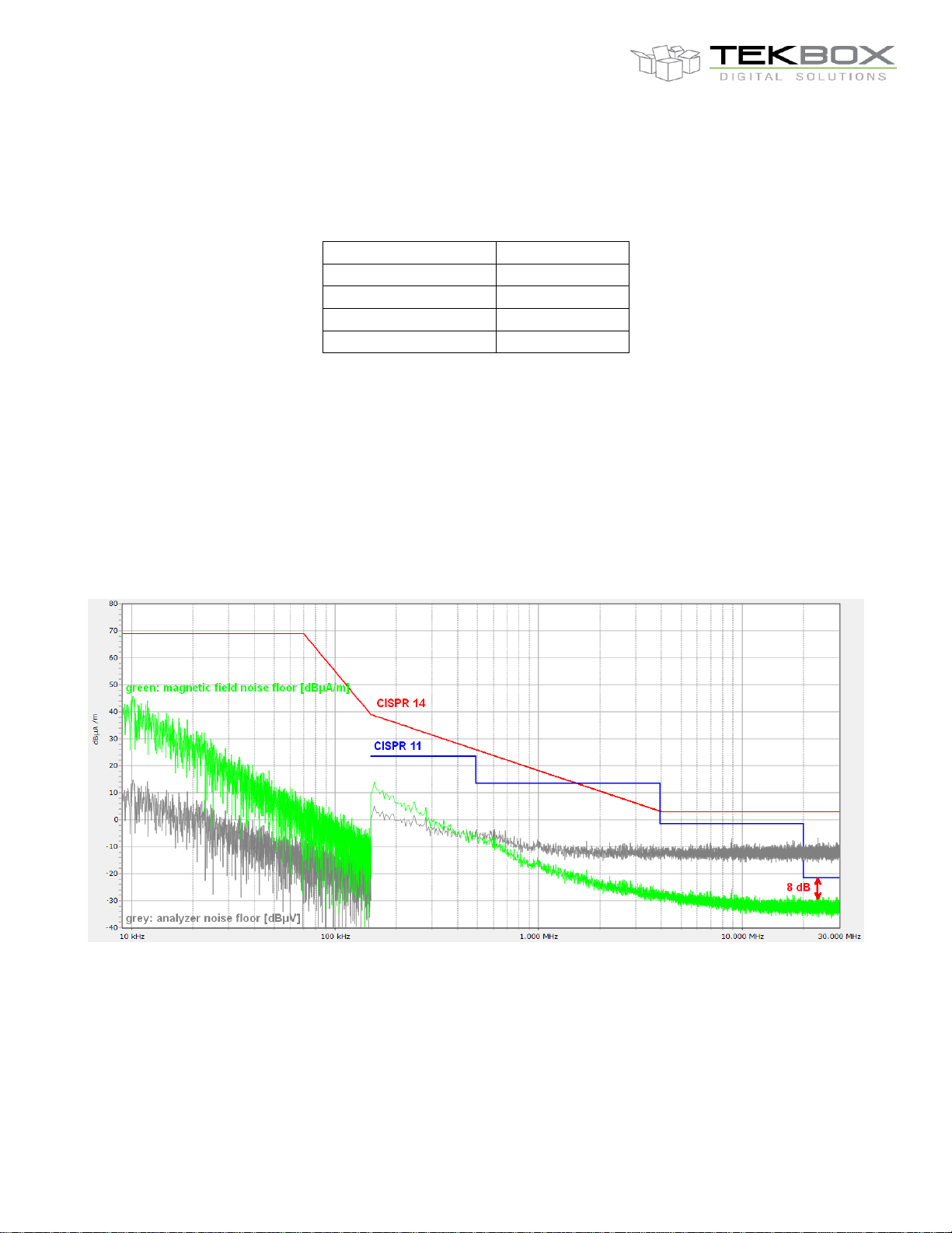
The above screenshot shows the magnetic field noise floor of a set up consisting of a lowcost spectrum analyzer and the TBMA6-P loop antenna.
Analyzer Model: Siglent SSA3021X-Plus
Internal attenuator: 0 dB; internal pre-amplifier: ON; 9 kHz - 150 kHz: 200 Hz RBW; 150 kHz –
30 MHz: 9kHz RBW; Peak detector; sweep time according to CISPR 16 specification
Page 5
V1.0
TBMA6-P
Passive Loop Antenna
5
Red limit line: CISPR 14 Magnetic field strength limits for induction cooking appliances
Blue limit line: CISPR 11 Class A, Group 2, 30 meters, in situ
The blue line represents the toughest limit of all CISPR standards in the range 150 kHz to 30
MHz.
The red line represents the toughest limit of all CISPR standards in the range 9 kHz to 150
kHz.
Comparing the magnetic field base noise with the limit lines shows that the TBMA6-P together
with the Siglent SSA3021X-Plus provide sufficient sensitivity for all CISPR specified radiated
emission measurements in the range 9 kHz to 30 MHz
6 Ordering Information
Part Number
Description
TBMA6-P
TBMA6-P transducer + corrugated, slotted coaxial cable for 60
cm loop + pistol grip tripod; beech wood box for transducer
TBMA6-CC30CM-D
corrugated, slotted coaxial cable for 30 cm loop
7 History
Version
Date
Author
Changes
V 1.0
22.9.2022
Mayerhofer
Creation of the preliminary document
www.tekbox.com
TekBox Digital Solutions Vietnam Pte. Ltd.
Factory 4, F4, Lot I-3B-1, Saigon Hi-Tech Park, Tan Phu Ward, District 9, Ho Chi Minh City, Vietnam
 Loading...