

Page 1
V1.0
1
TBMA4
`
1 GHz – 8 GHz Double Ridged Horn Antenna
1 Introduction
CISPR 16 divides the frequency range into several bands and defines specific antennas for each of these bands.
For the frequency range above 1 GHz, CISPR 16 specifies using wideband horn antennas for radiated noise
measurements.
Standard wideband horn antennas for EMC applications are quite costly and cover a frequency range far wider
than available on typical low cost EMC pre-compliance spectrum analyzers. In order to provide an antenna
optimized for pre-compliance EMC testing applications above 1 GHz, Tekbox designed the TBMA4 double ridged
horn measurement antenna.With its moderate price, it is an affordable product for radiated noise EMC precompliance testing and generating defined field strengths.
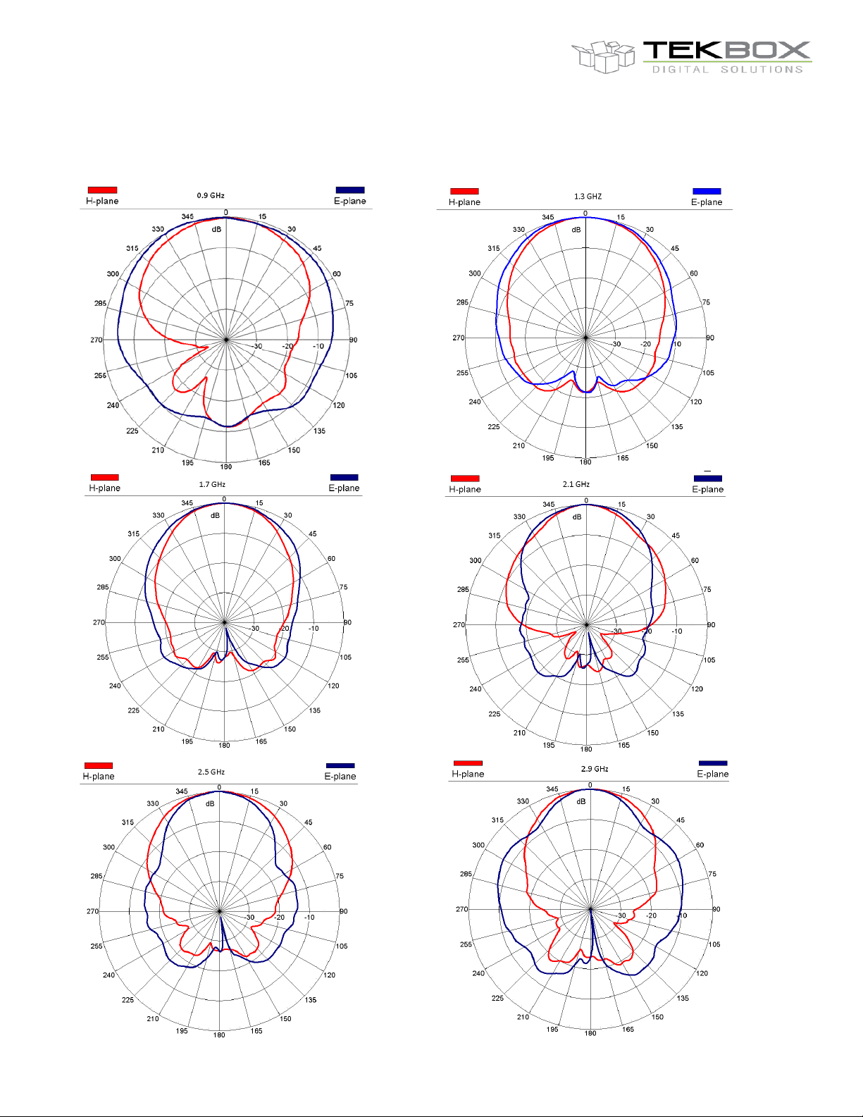
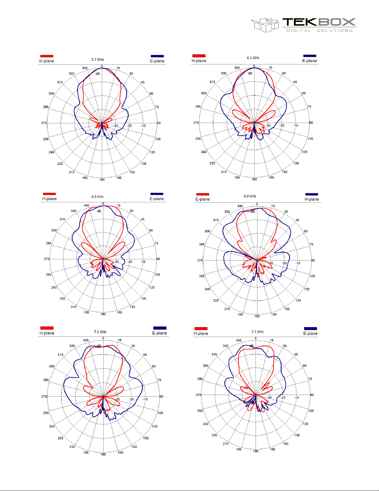
The TBMA4 is characterized from 1 GHz to 8 GHz and has a directional pattern typical for double ridged horn
antennas.
.
2 Product overview
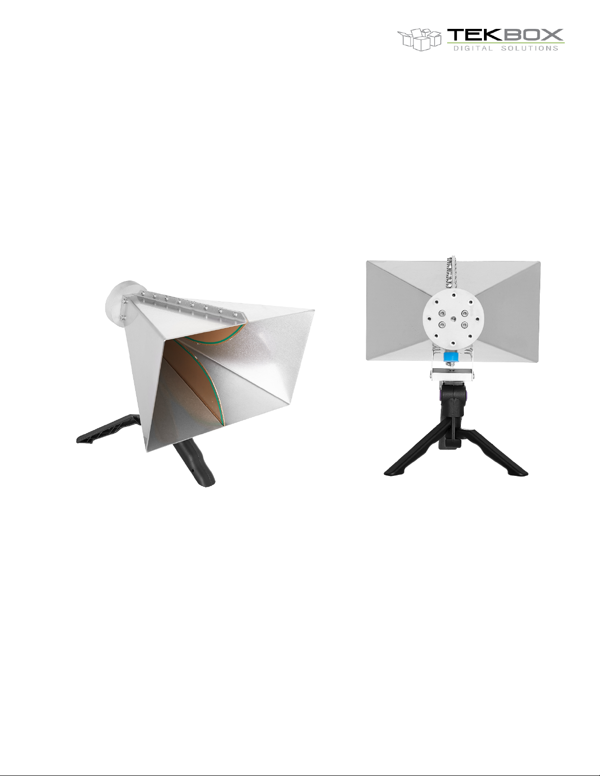
The TBMA4 is a small double ridged horn antenna, with its radiating element made from edge plated PCB
substrate. The housing is made from stainless steel. It is equipped with a standard female N-connector and comes
together with a “pistol-grip” tripod. A standard ¼” thread on the bottom of the antenna makes it easy to connect it
to most standard tripods. Optionally, the antenna can be equipped with an indexed mounting plate on its rear. This
accessory has a 6mm threaded hole in its centre and radially positioned 4mm threaded holes in 45° steps, typical
for most horn antennas.
Page 2
V1.0
2
TBMA4
`
1 GHz – 8 GHz Double Ridged Horn Antenna
3 Technical specifications
- Type: double ridged horn
- Frequency range: 1 GHz – 8 GHz
- Nominal impedance: 50 Ω
- Connector: N type female
- Maximum continuous input RF power: 100 W
- Isotropic gain: 6 … 14 dBi
- Antenna factor: 24 … 43 dB/m
- Front to back ratio: avg. 20 dB
- Voltage Standing Wave Ratio (VSWR): < 3:1 over the entire frequency range; < 2:1 average
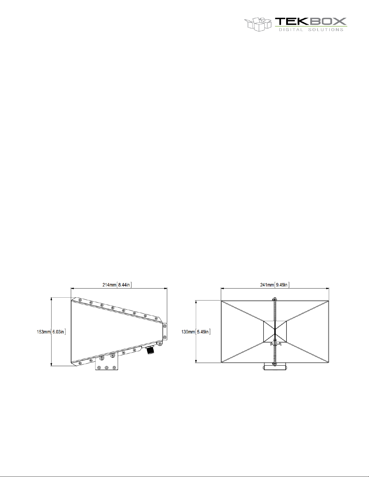
- Width: 241 mm (9.49 “)
- Height: 153 mm (6.03 “)
- Depth: 214 mm (8.44 “)
- Weight: 1.4 kg (3.08 lbs)
- Tripod Adapter Thread Size: ¼”
- Indexed rear mounting flange
Page 3

V1.0
3
Frequency
Wavelength
Gain (Isotropic)
Gain (Dipole)
Antenna Factor
MHz m dBi
dBd
dB/m
1000
0.300
6.17
4.02
24.13
1200
0.250
6.86
4.71
25.02
1400
0.214
7.30
5.15
25.92
1600
0.188
8.22
6.07
26.16
1800
0.167
9.85
7.70
25.56
2000
0.150
10.66
8.51
25.66
2200
0.136
7.41
5.26
29.74
2400
0.125
9.00
6.85
28.90
2600
0.115
10.98
8.83
27.62
2800
0.107
10.23
8.08
29.01
3000
0.100
9.94
7.79
29.90
3200
0.094
10.52
8.37
29.88
3400
0.088
11.92
9.77
29.01
3600
0.083
11.40
9.25
30.03
3800
0.079
11.60
9.45
30.30
4000
0.075
11.68
9.53
30.66
4200
0.071
12.41
10.26
30.35
4400
0.068
12.13
9.98
31.04
4600
0.065
11.84
9.69
31.72
4800
0.063
12.39
10.24
31.53
5000
0.060
12.54
10.39
31.74
5200
0.058
12.85
10.70
31.77
5400
0.056
14.62
12.47
30.33
5600
0.054
13.96
11.81
31.30
5800
0.052
11.50
9.35
34.07
6000
0.050
11.02
8.87
34.84
6200
0.048
10.28
8.13
35.87
6400
0.047
9.61
7.46
36.81
6600
0.045
8.95
6.80
37.74
6800
0.044
8.81
6.66
38.14
7000
0.043
7.55
5.40
39.65
7200
0.042
7.95
5.80
39.50
7400
0.041
7.50
5.35
40.18
7600
0.039
7.22
5.07
40.70
7800
0.038
7.51
5.36
40.63
8000
0.038
5.44
3.29
42.92
TBMA4
`
1 GHz – 8 GHz Double Ridged Horn Antenna
4 TBMA4 Antenna characterization
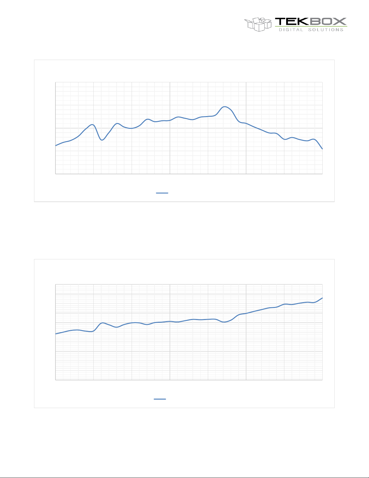
4.1 Gain & Antenna Factor versus frequency
Page 4
V1.0
4
0.00
5.00
10.00
15.00
20.00
1000 2000 3000 4000 5000 6000 7000 8000
Isotropic Gain
Gain (isotropic] [dBi]
0.00
5.00
10.00
15.00
20.00
25.00
30.00
35.00
40.00
45.00
50.00
1000 2000 3000 4000 5000 6000 7000 8000
Antenna factor
Antenna factor [dB/m]
TBMA4
`
1 GHz – 8 GHz Double Ridged Horn Antenna
1 GHz…8 GHz, Isotropic Gain of TBMA4
1 GHz…8 GHz, Antenna Factor of TBMA4
Page 5
V1.0
5
TBMA4
`
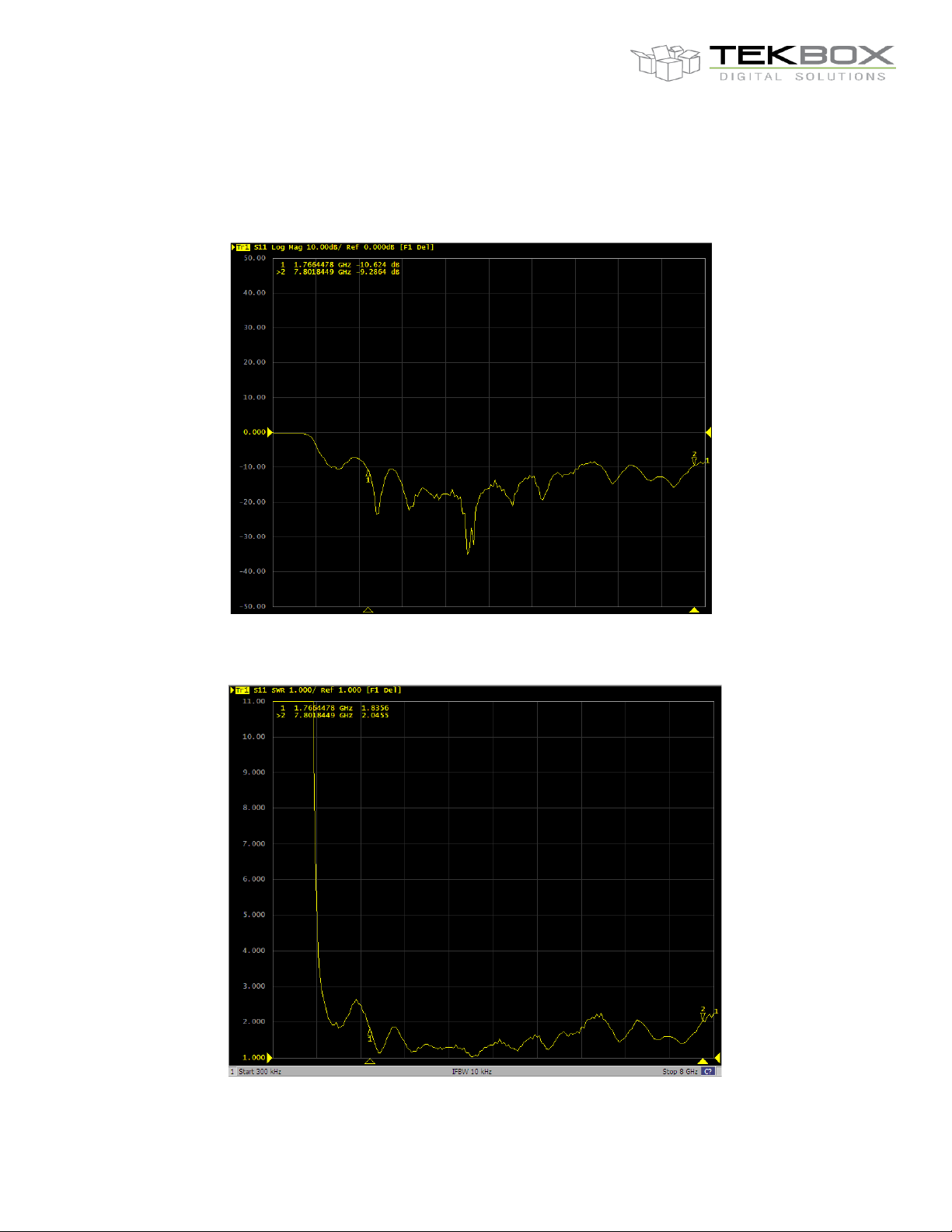
4.2 TBMA4 Return Loss / VSWR
1 GHz – 8 GHz Double Ridged Horn Antenna
TBMA4, S11, 300 kHz…8 GHz
TBMA4, VSWR, 300 kHz…8GHz
Page 6
V1.0
6
TBMA4
`
4.3 Directional plots
1 GHz – 8 GHz Double Ridged Horn Antenna
Page 7

V1.0
7
TBMA4
`
1 GHz – 8 GHz Double Ridged Horn Antenna
Page 8
V1.0
8
TBMA4
`
1 GHz – 8 GHz Double Ridged Horn Antenna
Page 9
V1.0
9
Conversion 3 m to 1 m
add 9.5 dB to the 3m limits
Conversion 10 m to 1 m
add 20 dB to the 10m limits
Conversion 10 m to 3 m
add 10.5 dB to the 10m limits
𝑃"= 𝑃$+ &20𝑙𝑜𝑔
,
-
,
.
𝐷$ is the actual measurement distance and
𝐷"&
𝑃$ is the RF power measured in the actual measurement distance.
𝑃" represents the calculated equivalent RF power in the distance specified in the relevant standard.
Part Number
Description
TBMA4
1 GHz – 8 GHz double ridged horn measurement antenna, mini tripod
Version
Date
Author
Changes
V1.0
9.11.2020
Mayerhofer
Creation of the document
TBMA4
`
1 GHz – 8 GHz Double Ridged Horn Antenna
5 Application
The TBMA4 was designed, targeting radiated noise EMC pre-compliance measurements in the frequency range
1 GHz to 8 GHz. To In order to make optimum use of the TBMA4, a few details need to be considered:
The antenna factor has to be added to the measurement result in order to convert the level [dBm] into an equivalent
electrical field strength [dBm]. This conversion will also add to the base noise level of the spectrum analyzer which
reduces the margin between base noise and limit lines.
If there is no risk of overloading the spectrum analyzer RF-input, decrease the internal attenuation to 0 dB and
turn on the pre-amplifier to optimize the dynamic range of the measurement. Use a low loss coaxial cable to
connect the antenna to the spectrum analyzer. CISPR 16 specifies a resolution bandwidth of 1 MHz for frequencies
above 1 GHz. Consequently, lowering the RBW cannot be utilized to reduce the base noise level. However, in
cases of standards with challenging limits with respect to the base noise level of pre-compliance spectrum
analyzers, the antenna could be moved closer to the DUT and the limits converted accordingly. This will result in
additional margin between base noise and limit levels. Since the TBMA4 is used for measurements above 1 GHz,
10m or 3m distance limits could be converted to 1m distance limits, resulting in 20dB or 10 dB additional margin
to the base noise level. With 1m distance and measurement frequencies > 1GHz, the antenna is already in the far
field for any frequency.
Use the table below in order to convert limits to another measurement distance:
The table above is based on following formula:
where
[dBm]
is the specified distance in the relevant standard.
6 Ordering Information
7 History
 Loading...