

Page 1
V1.3
TBLC08
TBLC08 50mH AC-LISN
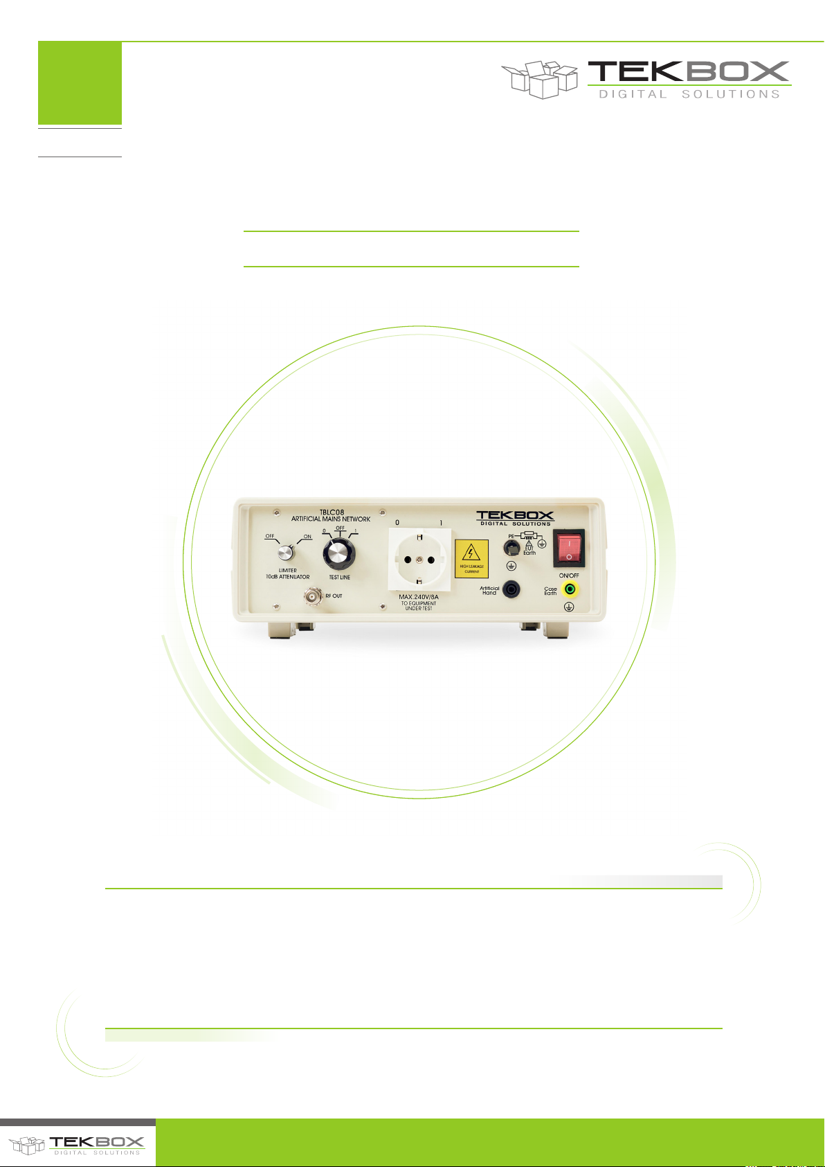
The TBLC08 is a Line Impedance Stabilization Network for the measurement of line-conducted
interference within the range of 9kHz to 30MHz, according to the CISPR16 standard. The device
is designed for testing single phase, AC-powered equipment with supply voltages up to maximum
260V. Conducted noise can be measured on the phase and on the neutral conductor. The TBLC08 is
equipped with a switchable limiter/attenuator and an artificial hand connection. The device is available
with country-specific DUT connectors.
© 2017 TEKBOX DIGITAL SOLUTIONS
50/11 TRUONG SON, TAN BINH DISTRICT, HO CHI MINH CITY | TEL +84 (83)5471340 | E-MAIL [email protected] | www.tekbox.net
Page 2
V1.3
TBLC08
TBLC08 50mH AC-LISN
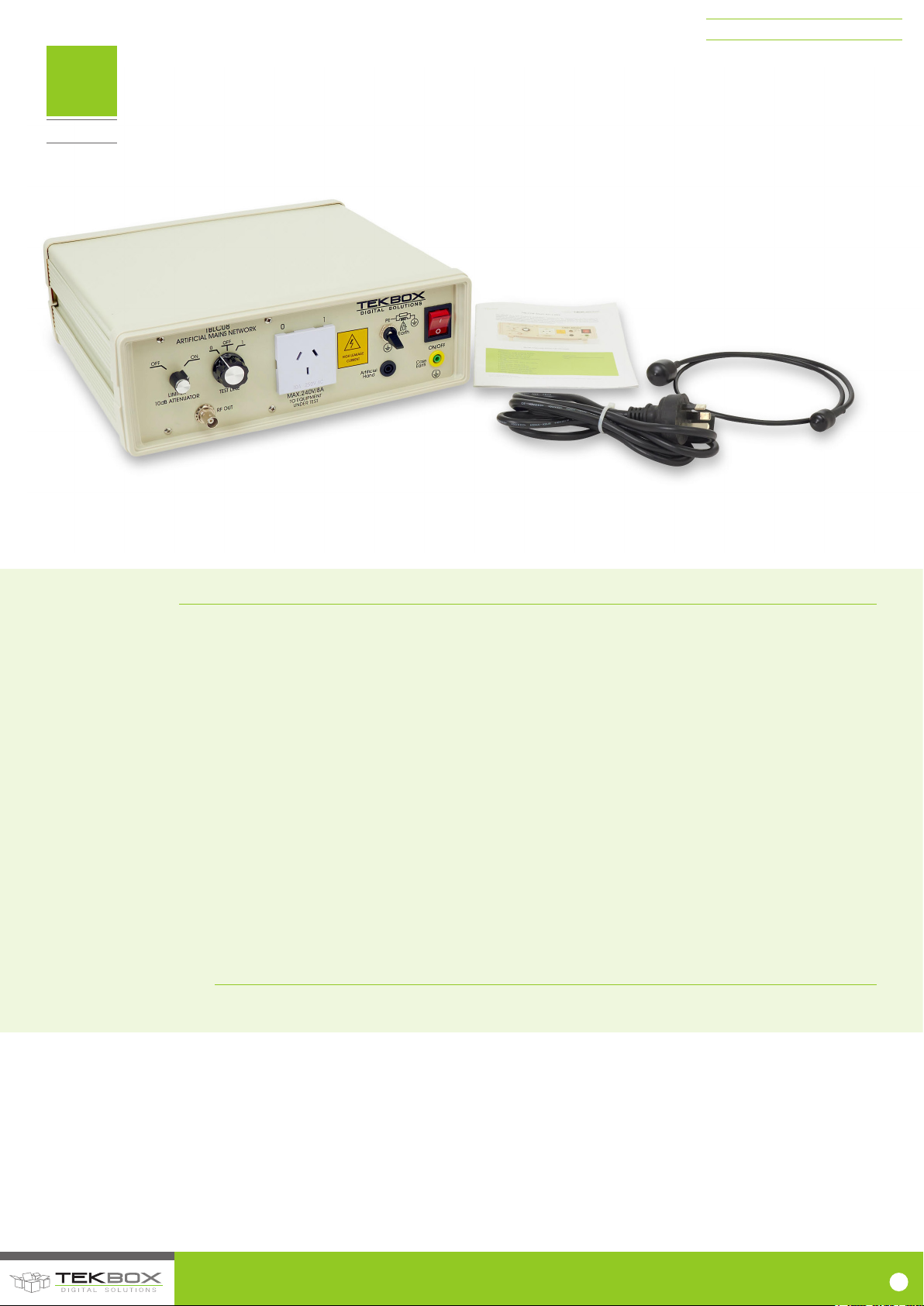
TBLC08 with Australian AS/NZS 3112 socket variant
FEATURES
• Frequency range: 9 kHz to 30 MHz
• Impedance: 50 Ω ‖ (50 µH + 5 Ω)
• Artificial hand: 220 pF + 511 Ω
• Switchable PE: 50 Ω ‖ 50 µH
• Limiter / attenuator: 150 kHz to 30 MHz; 10 dB
• Air core inductors
• Line voltage: max. 240V / 50 – 60 Hz, CAT ‖
• Max. current: 8A @ 23°C
• DUT socket: country specific
• Measurement connector: 50 Ω BNC
• Power connector: IEC 60320 C13
• Operating Temperature Range:
• +5°C … + 40°C; 5% to 80% RH
• Safety: Safety Class I, IEC 1010-01
APPLICATION
• EMC pre-compliance testing of conducted noise
© 2017 TEKBOX DIGITAL SOLUTIONS
50/11 TRUONG SON, TAN BINH DISTRICT, HO CHI MINH CITY | TEL +84 (83)5471340 | E-MAIL of[email protected] | www.tekbox.net
1
Page 3

V1.3
TBLC08
CONTENTS
TBLC08 50mH AC-LISN
SAFETY 3
1 INTRODUCTION 3
1.1 PRE-COMPLIANCE TESTING OF CONDUCTED EMISSIONS 3
1.2 LINE IMPEDANCE STABILIZATION NETWORKS 4
1.3 RF OUTPUT 4
1.4 INFORMATIVE SCHEMATIC 4
1.5 LABORATORY SET UP 5
1.6 GROUND PLANE 5
2 TBLC08 SPECIFICATIONS 5
2.1 CONFORMITY 5
2.2 SAFETY 5
2.3 SPECIFICATIONS 5
2.4 SUPPLY VOLTAGE 6
2.5 FRONT PANEL 6
2.6 REAR PANEL 7
2.7 IMPEDANCE 8
2.8 FREQUENCY RESPONSE, S21 FROM DUT PORT TO
RF PORT 8
2.9 CALIBRATION DATA ACCORDING TO CISPR 16 -1-2
ANNEX A8 10
2.10 PROTECTION 11
2.11 ARTIFICIAL HAND 12
3 OPERATION CHECKLIST 12
4 ORDERING INFORMATION 12
5 HISTORY 13
TABLES
Table 1 – Frequency response 9kHz to 300MHz, DUT connector Phase/Neutral to RF connector 9
Table 2 – TBLC08 LISN calibration data 10
Table 3 – Ordering Information 12
Table 4 – History 13
PICTURES
Figure 1 – Basic AC LISN set up: impedance levels 4
Figure 2 – AC LISN, informative schematic 4
Figure 3 – Conducted noise pre-compliance measurement setup 5
Figure 4 – Front panel layout 6
Figure 5 – DUT connector, pin assignment with reference to the rear power connector *) 6
Figure 6 – Rear panel layout 7
Figure 7 – Mains connector, pin assignment *) 7
Figure 8 – impedance vs. frequency at DUT terminals 8
Figure 9 – Frequency response 9kHz to 300MHz, DUT connector Phase/Neutral to RF connector 8
Figure 10 – Calibration set up according to CISPR 16-1-2 Annex A.8. 10
Figure 11 – Example from CISPR 16, portable electric saw with artificial hand 12
© 2017 TEKBOX DIGITAL SOLUTIONS
50/11 TRUONG SON, TAN BINH DISTRICT, HO CHI MINH CITY | TEL +84 (83)5471340 | E-MAIL of[email protected] | www.tekbox.net
2
Page 4
TBLC08 50mH AC-LISN
V1.3
TBLC08
SAFETY
Operating an AC LISN involves dealing with potentially lethal voltages and high ground leakage currents.
Read this manual carefully and be sure to understand the operation of an AC LISN. Make sure that the
conducted noise pre – compliance test equipment is set up correctly and that the necessary earth connections
are reliably bonded to avoid the risk of lethal electric shocks.
Make sure to understand the operation of the attenuator / limiter to avoid any damage to your test receiver
or spectrum analyzer.
Do not carry out any modifications or manipulations of the TBLC08. User maintenance of the TBLC08 is
strictly limited to the replacement of the fuses.
1. INTRODUCTION
1.1. PRE-COMPLIANCE TESTING OF CONDUCTED EMISSIONS
Full compliance measurement of AC mains supplied products requires
a high end set up consisting of an anechoic or screened chamber, a
measurement receiver that complies with the requirements of CISPR
16, a 50µH LISN and a suitable table for the measurement setup. Great
effort and cost ensures optimum accuracy and repeatability.
Pre-compliance measurements target to give an approximation of the
EMC performance of the Device Under Test at a fraction of the cost of
full compliance testing. The measurement receiver can be replaced by
a spectrum analyzer with suitable sensitivity, bandwidth and detectors.
The advent of affordable spectrum analyzers with EMI detectors such as
the DSA815 from Rigol or similar products made EMC pre-compliance
testing affordable for any company which develops electronic products.
Together with test accessories from Tekbox, EMC pre-compliance setups cost hardly more than a standard oscilloscope a few years ago.
Eliminate uncertainty before going to the test house for compliance
testing. There is hardly anything that can give you a return on invest as
quickly as EMC pre compliance test equipment.
© 2017 TEKBOX DIGITAL SOLUTIONS
50/11 TRUONG SON, TAN BINH DISTRICT, HO CHI MINH CITY | TEL +84 (83)5471340 | E-MAIL of[email protected] | www.tekbox.net
3
Page 5
1.2. LINE IMPEDANCE STABILIZATION NETWORKS
TBLC08 50mH AC-LISN
Any LISN (line impedance stabilization network) is basically a kind of
filter. A LISN is always inserted between the supply input terminals of
the DUT (Device Under Test) and the supply which is used to power the
DUT. It presents a defined impedance for the noise which is produced by
the DUT and emitted via the supply cables of the Device Under Test. The
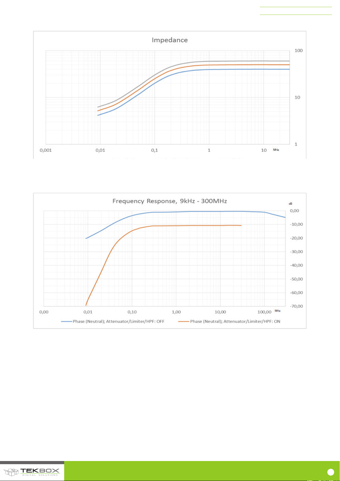
impedance seen by the RF emissions is 50 Ohms║ 50µH which results in
50 Ohms for the most part of the specified frequency range. Only at the
Figure 1 – Basic AC LISN set up: impedance levels.
Furthermore, the AC LISN attenuates noise originating from the incoming mains supply towards the Receiver/Analyzer and DUT.
lower edge of its bandwidth, the impedance decreases. This impedance
curve is specified in the corresponding test standards. Having a defined
impedance for the emissions at the DUT terminals eliminates any
influence of the power source impedance. Consequently, the measured
amplitudes of the noise spectrum become independent of the power
source characteristics:
1.3. RF OUTPUT
The RF output section is AC coupled to either the phase or neutral line.
The path can be selected by a rotary switch at the front panel. The RF
section also contains an attenuator/limiter and a high pass filter.
Purpose of the high pass filter is the attenuation of harmonics
originating from the mains supply. The attenuator/limiter protects the
measurement receiver / spectrum analyzer input from high amplitude
pulse transients. The phase and neutral line can be the source of
such transients, in particular those produced on turning off the DUT.
Consequently it is highly advised to disconnect the spectrum analyzer
via cable or line selector switch in OFF position while turning on/off the
DUT. Use external attenuators and the built in attenuator/limiter to check
the lower frequency range for spurious with high power until you are
sure, that the spurious levels are not exceeding the maximum input level
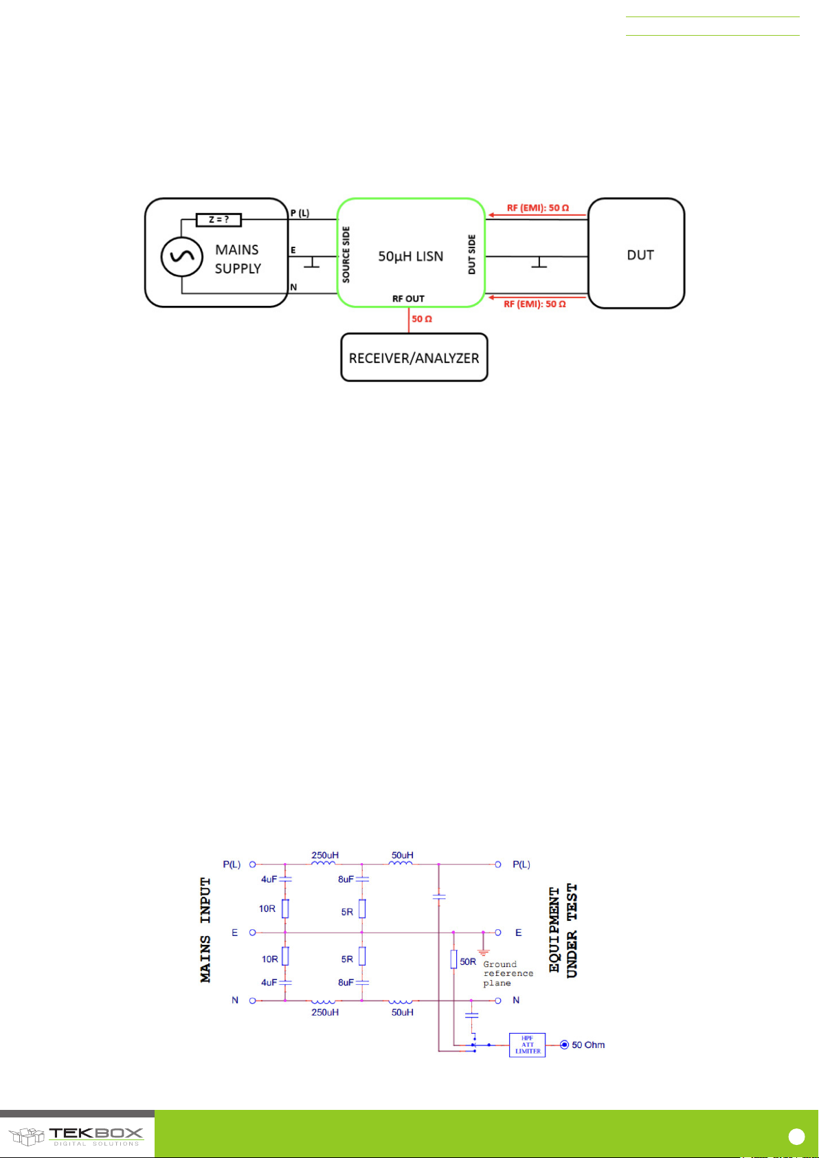
1.4. INFORMATIVE SCHEMATIC
The picture below shows the basic topology and the values of the
main components of an AC LISN which is used to perform conducted
emissions testing. It originates from VDE conducted emissions testing
and is also used for CISPR15 testing of lighting products. It includes
additional capacitors and inductors for filtering and has an operating
frequency range of 9kHz to 30MHz.
range of the spectrum analyzer. For pre-compliance measurements the
Attenuator/Limiter should be turned off then, as the limiter is a nonlinear component which can create intermodulation and falsify the
measurement result. Use external attenuators instead, if necessary
WARNING: Ensure that the spectrum analyzer RF input is disconnected
when powering on or powering off the DUT. Leave the attenuator always
turned on, if the DUT switches inductive loads during operation or in case
of any uncertainty concerning the DUT characteristics. After ensuring that
the spectrum analyzer is not over loaded, turn the Attenuator/Limiter Off
or use external attenuators to avoid potential intermodulation products
creating a measurement error.
NOTE the high capacitor values which cause considerable blind
current at 50Hz/60Hz line voltages. Direct connection to the mains
outlet would cause tripping of the ground fault switch. Refer to
the next chapter on how to set up the AC LISN in a standard
laboratory environment.
Figure 2 – AC LISN, informative schematic
© 2017 TEKBOX DIGITAL SOLUTIONS
50/11 TRUONG SON, TAN BINH DISTRICT, HO CHI MINH CITY | TEL +84 (83)5471340 | E-MAIL of[email protected] | www.tekbox.net
4
Page 6
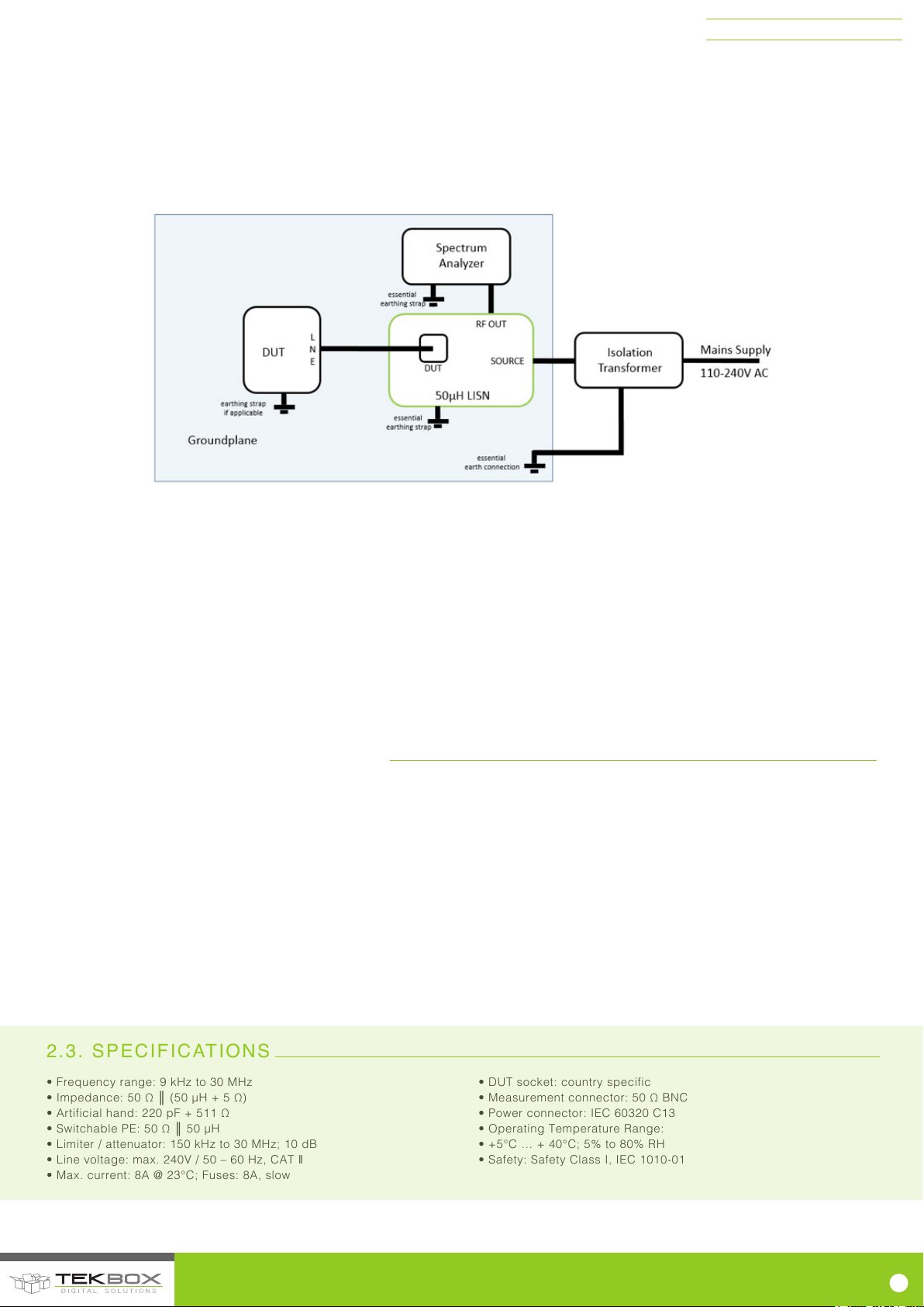
1.5. LABORATORY SET UP
TBLC08 50mH AC-LISN
The DUT shall be isolated and elevated from the ground plane.
The spectrum analyzer shall measure the conducted emissions on both
line and neutral.
The value of the parallel combination of the capacitors is 12µF from line
and neutral to ground. This causes around 0.75A flowing into the earth
connection and would trip the ground fault switch. Hence, an insulation
Figure 3 – Conducted noise pre-compliance measurement setup
SAFETY: Ensure that all required earth connections are reliably bonded and that the isolation transformer can supply the required load current.
transformer is required for any mains supply which is protected by a
residual current device or ground fault (earth leakage) circuit breaker
and good grounding is essential for safety.
For the exact details of the set up and for the limits of conducted
emissions refer to the CISPR 16 or other relevant applicable standards.
1.6. GROUND PLANE
Any voltage measurement must be made against a common circuit
node which can be referred to as the “zero volt” reference. In order
to provide a low impedance zero volt reference for RF measurements,
a metal sheet must be provided as ground plane. All ground straps
between equipment and ground plane shall be as short as possible
and fastened with screws. Exact details on the size of the ground plane
and the arrangement of the equipment and interconnecting cables are
described in the applicable standards.
In a pre-compliance test set up, as a rule of thumb, the size of the
ground plane shall be large enough to accommodate all involved
equipment and exceed at least 10cm each side.
2. TBLC08 SPECIFICATIONS
2.1. CONFORMITY
The TBLC08 is compliant with Safety Class I according IEC 1010-1.
(EN 61010-1: 1993 / IEC (CEI) 1010-1: 1990 A 1: 1992, EN 61010-1/A2: 1995 / IEC 1010-1/A2: 1995 /)
Rated Pollution degree: 2
Overvoltage category: II
EMC: EN61326-1/A1
2.2. SAFETY
In order to ensure safe operations, the user must follow all safety
relevant information of this manual. All housing parts are connected
with the earth conductor of the power conductor and with the ground
strap block at the rear panel of the housing. It is not allowed to carry out
any modifications or manipulations of the TBLC08.
2.3. SPECIFICATIONS
• Frequency range: 9 kHz to 30 MHz
• Impedance: 50 Ω ║ (50 µH + 5 Ω)
• Artificial hand: 220 pF + 511 Ω
• Switchable PE: 50 Ω ║ 50 µH
• Limiter / attenuator: 150 kHz to 30 MHz; 10 dB
• Line voltage: max. 240V / 50 – 60 Hz, CAT ‖
• Max. current: 8A @ 23°C; Fuses: 8A, slow
© 2017 TEKBOX DIGITAL SOLUTIONS
50/11 TRUONG SON, TAN BINH DISTRICT, HO CHI MINH CITY | TEL +84 (83)5471340 | E-MAIL of[email protected] | www.tekbox.net
• DUT socket: country specific
• Measurement connector: 50 Ω BNC
• Power connector: IEC 60320 C13
• Operating Temperature Range:
• +5°C … + 40°C; 5% to 80% RH
• Safety: Safety Class I, IEC 1010-01
5
Page 7
TBLC08 50mH AC-LISN
2.4. SUPPLY VOLTAGE
The TBLC08 does not require any particular voltage settings. It can be operated with any supply voltage which does not exceed 240V, 50Hz/60Hz.
2.5. FRONT PANEL
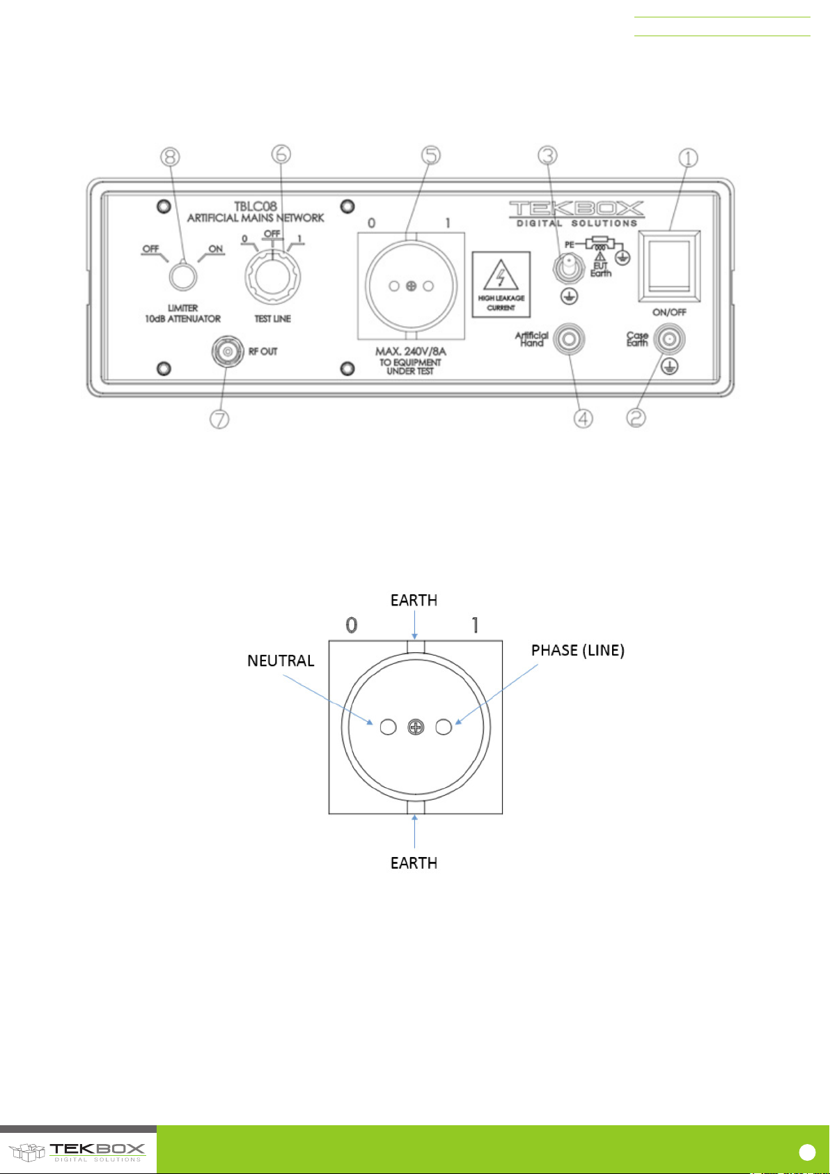
Figure 4 – Front panel layout
1) Mains switch
2) Auxiliary case earth connector, safety banana jack
3) Protective Earth switch to connect DUT earth either directly to case earth, or via 50µH ║ 50 Ohm
4) Artificial hand connector, safety banana jack
5) DUT socket, country specific
6) RF path selection, 0 (neutral), OFF, 1 (phase)
7) 50 Ω RF output, BNC jack
8) Limiter + 10 dB attenuator + 150kHz high pass filter switch
Figure 5 – DUT connector, pin assignment with reference to the rear power connector *)
*) Provided that the TBLC08 is correctly connected to the mains power outlet
© 2017 TEKBOX DIGITAL SOLUTIONS
50/11 TRUONG SON, TAN BINH DISTRICT, HO CHI MINH CITY | TEL +84 (83)5471340 | E-MAIL of[email protected] | www.tekbox.net
6
Page 8
2.6. REAR PANEL
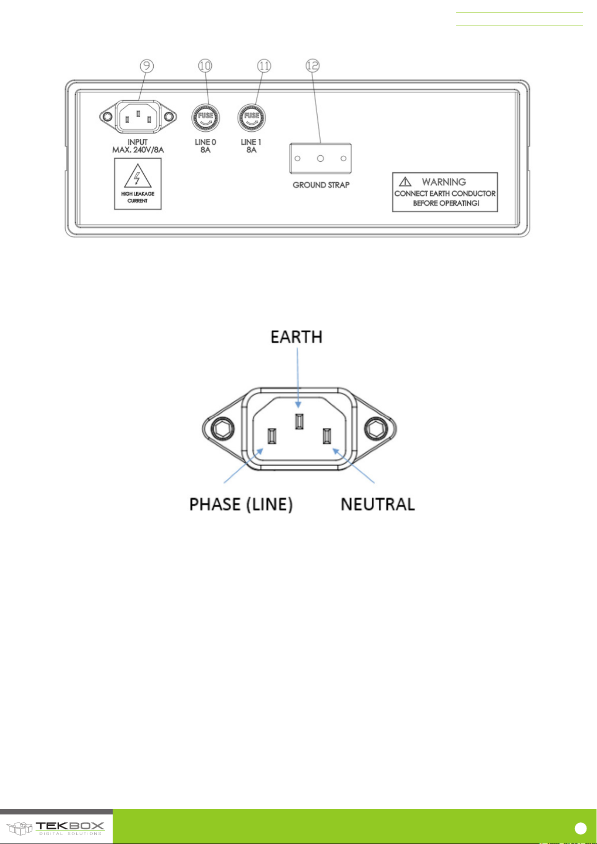
9) Power connector: IEC 60320 C13
10) Fuse, 8A, slow
11) Fuse, 8A, slow
12) Ground strap block, connected to earth, 4mm thread
TBLC08 50mH AC-LISN
Figure 6 – Rear panel layout
*) Provided that the TBLC08 is correctly connected to the mains power outlet
Figure 7 – Mains connector, pin assignment *)
© 2017 TEKBOX DIGITAL SOLUTIONS
50/11 TRUONG SON, TAN BINH DISTRICT, HO CHI MINH CITY | TEL +84 (83)5471340 | E-MAIL of[email protected] | www.tekbox.net
7
Page 9
2.7. IMPEDANCE
TBLC08 50mH AC-LISN
Figure 8 – impedance vs. frequency at DUT terminals
2.8. FREQUENCY RESPONSE, S21 FROM DUT PORT TO RF PORT
Figure 9 – Frequency response 9kHz to 300MHz, DUT connector Phase/Neutral to RF connector
© 2017 TEKBOX DIGITAL SOLUTIONS
50/11 TRUONG SON, TAN BINH DISTRICT, HO CHI MINH CITY | TEL +84 (83)5471340 | E-MAIL of[email protected] | www.tekbox.net
8
Page 10

TBLC08 50mH AC-LISN
Frequency [MHz]
Path: DUT connector – RF connector [dB]
Phase (Neutral); Att./Limiter/HPF: OFF
Path DUT connector – RF connector [dB]
Phase (Neutral); Att./Limiter/HPF: ON
0,009 -20,30 -69,30
0,01 -19,64 -65,23
0,02 -14,57 -44,79
0,03 -11,18 -32,36
0,04 -8,90 -25,43
0,05 -7,33 -21,73
0,06 -6,17 -19,39
0,07 -5,28 -17,74
0,08 -4,56 -16,46
0,09 -4,03 -15,46
0,10 -3,58 -14,72
0,11 -3,23 -14,13
0,12 -2,94 -13,68
0,13 -2,70 -13,34
0,14 -2,49 -13,07
0,15 -2,32 -12,66
0,20 -1,67 -11,87
0,25 -1,29 -11,37
0,30 -1,08 -11,06
0,40 -1,06 -11,04
0,50 -1,04 -11,03
0,60 -1,02 -11,02
0,70 -0,98 -10,98
0,80 -0,94 -10,97
0,90 -0,89 -10,94
1,00 -0,86 -10,93
2,00 -0,53 -10,81
3,00 -0,52 -10,79
4,00 -0,52 -10,81
5,00 -0,52 -10,81
10,00 -0,51 -10,80
15,00 -0,48 -10,72
20,00 -0,44 -10,71
25,00 -0,45 -10,73
30,00 -0,45 -10,80
50,00 -0,64
100,00 -1,10
150,00 -2,50
Table 1 – Frequency response 9kHz to 300MHz, DUT connector Phase/Neutral to RF connector
© 2017 TEKBOX DIGITAL SOLUTIONS
50/11 TRUONG SON, TAN BINH DISTRICT, HO CHI MINH CITY | TEL +84 (83)5471340 | E-MAIL of[email protected] | www.tekbox.net
9
Page 11
TBLC08 50mH AC-LISN
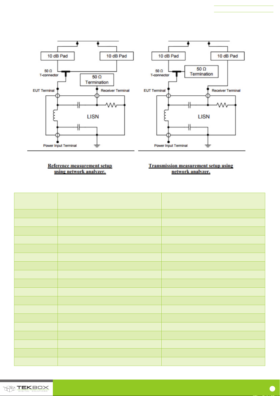
2.9. CALIBRATION DATA ACCORDING TO CISPR 16 -1-2 ANNEX A8
Calibration set up according to CISPR 16-1-2 Annex A.8.
Figure 10 – Calibration set up according to CISPR 16-1-2 Annex A.8.
Frequency [MHz]
Insertion loss neutral/phase attenuator/limiter
off [dB]
Insertion loss neutral/phase - attenuator/lter/limiter
0.03 -1.22 -23.4
0.05 -0.78 -15.8
0.1 -0.54 -12.2
0.15 -0.5 -11.4
0.25 -0.49 -10.95
0.3 -0.48 -10.88
0.35 -0.46 -10.72
0.4 -0.46 -10.72
0.45 -0.46 -10.72
0.5 -0.46 -10.72
0.55 -0.47 -10.72
0.6 -0.47 -10.72
on [dB]
0.65 -0.47 -10.72
0.7 -0.47 -10.72
0.75 -0.47 -10.72
0.8 -0.47 -10.72
0.85 -0.47 -10.72
0.9 -0.47 -10.72
© 2017 TEKBOX DIGITAL SOLUTIONS
50/11 TRUONG SON, TAN BINH DISTRICT, HO CHI MINH CITY | TEL +84 (83)5471340 | E-MAIL of[email protected] | www.tekbox.net
10
Page 12

TBLC08 50mH AC-LISN
0.95 -0.47 -10.72
1 -0.47 -10.72
2 -0.51 -10.74
3 -0.55 -10.78
4 -0.61 -10.81
5 -0.69 -10.89
6 -0.75 -10.92
7 -0.81 -11.01
8 -0.89 -11.07
9 -0.97 -11.14
10 -1.05 -11.24
11 -1.17 -11.33
12 -1.23 -11.37
13 -1.32 -11.47
14 -1.42 -11.59
15 -1.56 -11.73
16 -1.67 -11.85
17 -1.82 -12.03
18 -1.94 -12.16
19 -2.09 -12.29
20 -2.23 -12.48
21 -2.41 -12.67
22 -2.57 -12.84
23 -2.76 -13.05
24 -2.95 -13.29
25 -3.06 -13.51
26 -3.29 -13.65
27 -3.38 -13.78
28 -3.42 -13.81
29 -3.46 -14.86
30 -3.51 -13.95
Table 2, TBLC08 LISN calibration data
2 10. PROTECTION
The TBLC08 offers several levels of protection to prevent surges
appearing at the input of the measurement receiver or analyzer. Both
the neutral line and phase line are equipped with a 275V varistor to
ground. The RF path is always protected by a 90V gas discharge tube
and a pair of TVS diodes (5.4V break down voltage, 9.8V clamping
© 2017 TEKBOX DIGITAL SOLUTIONS
50/11 TRUONG SON, TAN BINH DISTRICT, HO CHI MINH CITY | TEL +84 (83)5471340 | E-MAIL of[email protected] | www.tekbox.net
voltage, 1A peak surge current). When the attenuator/limiter switch is
in “ON” position, a 10dB attenuator and a Schottky diode limiter offer
additional protection. Furthermore, the attenuator/limiter path contains
a 150kHz high pass filter.
11
Page 13
2 11. ARTIFICIAL HAND
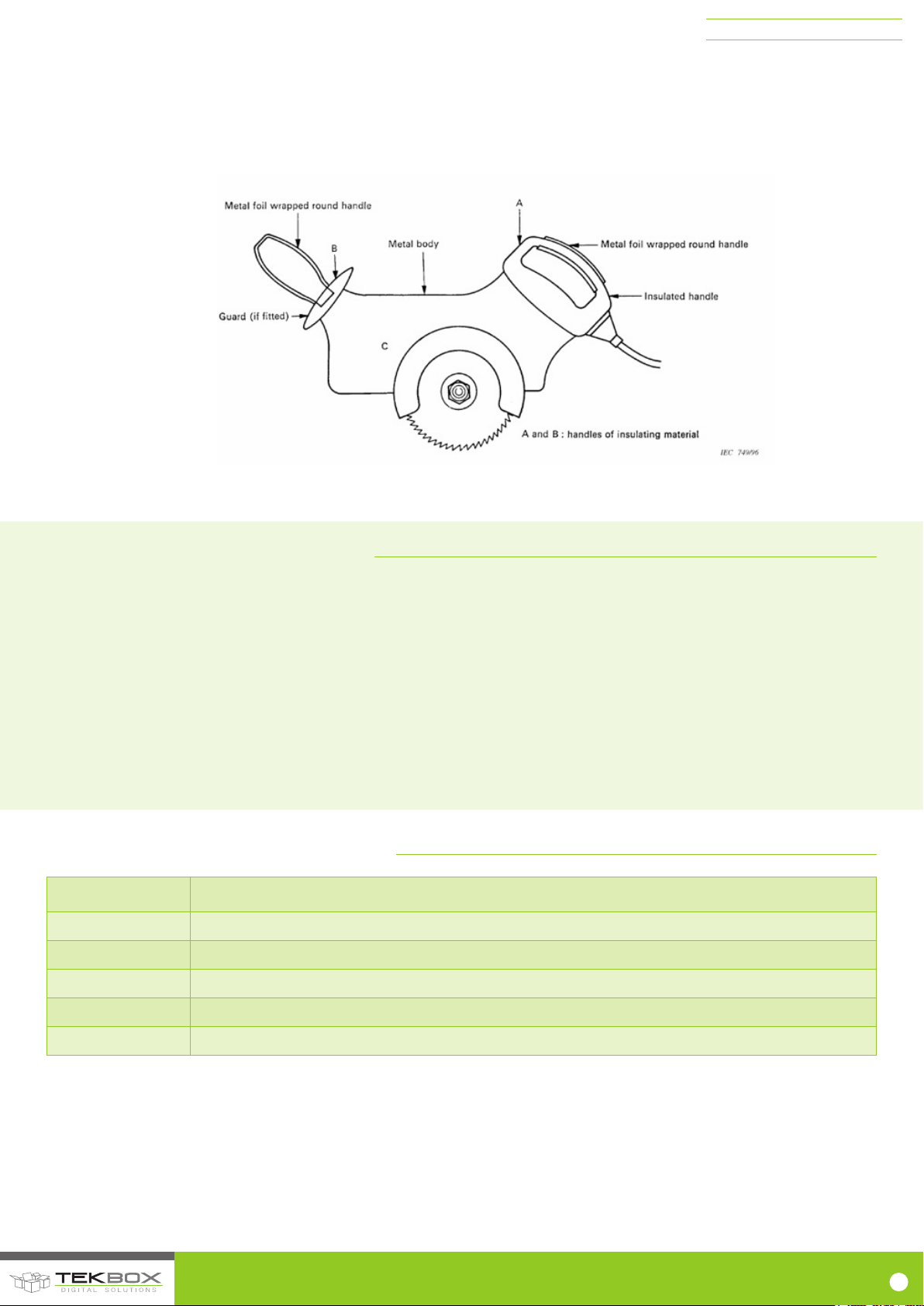
When performing conducted noise measurements with devices which
are held in hand, the artificial hand network mimics the influence of the
human hand. Examples for such devices are power tools, hair driers,
kitchen tools and similar equipment.
Figure 11 – Example from CISPR 16, portable electric saw with artificial hand
TBLC08 50mH AC-LISN
Insulated housing sections that are touched by the hand when operating
the equipment are covered with metal foil and connected to the artificial
hand jack.
3. OPERATION CHECKLIST
• Setup the isolation transformer, TBLC08, DUT and spectrum analyzer
according to Figure 3.
• Before powering the isolation transformer, measure the connectivity
between each equipment chassis and ground plane.
• Ensure that the supply cable of the isolation transformer, the supply
cable of the LISN, the supply cable of the spectrum analyzer and if
applicable the supply cable of the DUT contain a ground conductor.
• Ensure that the line selection switch of the TBLC08 is set to “OFF”.
• Ensure that the Protective Earth switch is set to direct ground position
• Ensure that the Limiter/Attenuator switch of the TBLC08 is in
“ON” position.
• Ensure that the power switch of the TBLC08 is in “OFF” position.
• Ensure that the DUT power switch is in “OFF” position.
• Power on the isolation transformer
• Power on the analyzer, set frequency, bandwidth, amplitude etc.
• Power on the TBLC08
• Power on the DUT
• Set the line selection switch to “0” or “1” to carry out the conducted
noise measurements. Disengage the Limiter/Attenuator for better
sensitivity and in order to avoid potential intermodulation.
• After finishing the measurement, proceed in reverse order. Take
special care to set the limiter/attenuator to “ON” and the line selection
switch to “OFF” before powering off the DUT.
4. ORDERING INFORMATION
Part Number Description
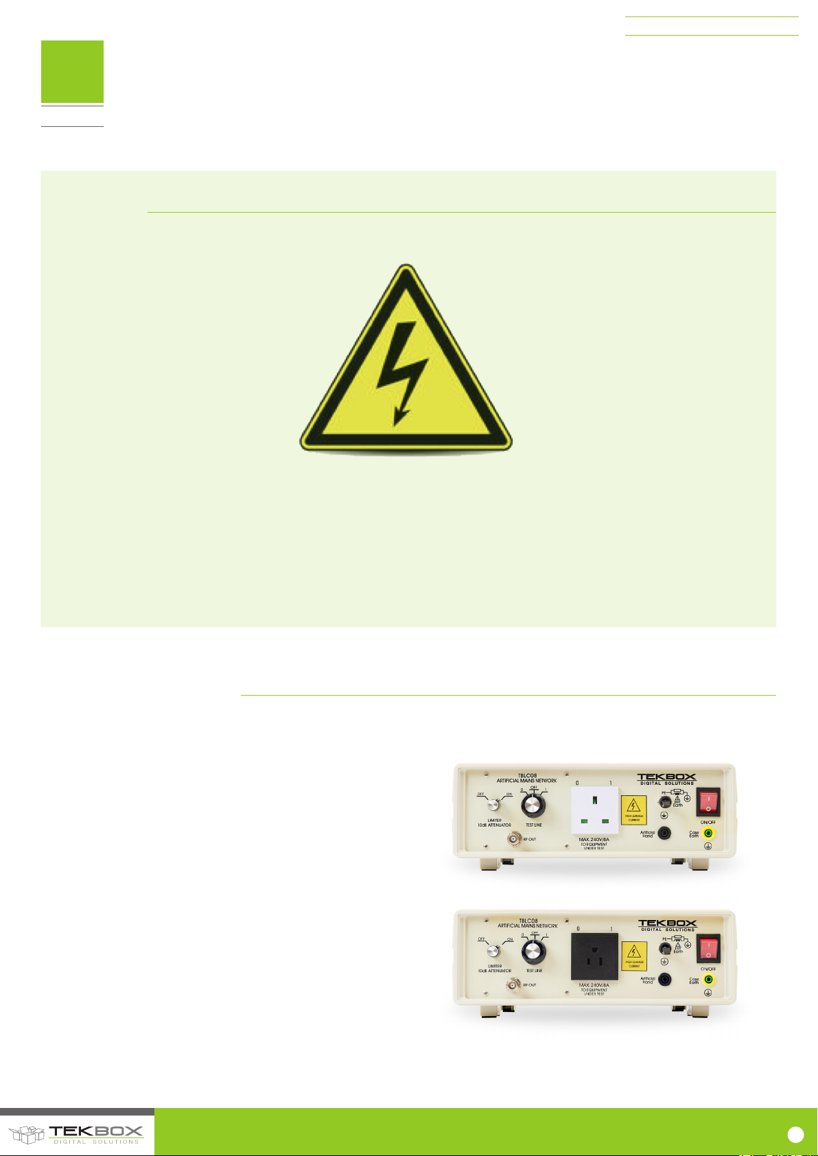
TBLC08-EU 50µH LISN with Schuko socket (CE7/3)
TBLC08-US 50µH LISN with US socket (NEMA 5-15, grounded, type B)
TBLC08-AU 50µH LISN with Australian socket (AS/NZS 3112:201)
TBLC08-GB 50µH LISN with English socket (BS1363)
TBLC08-xx Any other socket requirements upon customer request will have 2-3 weeks lead time
Table 3 – Ordering Information
© 2017 TEKBOX DIGITAL SOLUTIONS
50/11 TRUONG SON, TAN BINH DISTRICT, HO CHI MINH CITY | TEL +84 (83)5471340 | E-MAIL of[email protected] | www.tekbox.net
12
Page 14

5. HISTORY
Version Date Author Changes
V1.0 22.05.2015 MRH Creation of the document
V1.1 29.06.2015 MRH Update
V1.2 29.06.2015 MRH Updated chapter 1.3
V1.3 13.12.2017 MRH Updated chapter 1.3 and added chapter 2.9
TBLC08 50mH AC-LISN
Table 4 – History
© 2017 TEKBOX DIGITAL SOLUTIONS
50/11 TRUONG SON, TAN BINH DISTRICT, HO CHI MINH CITY | TEL +84 (83)5471340 | E-MAIL of[email protected] | www.tekbox.net
13
 Loading...