

Page 1
V1.1
TBGTC1
OPEN GTEM CELL FOR EMC PRE-COMPLIANCE TESTING
1
1 Introduction
The TBGTC1 open GTEM-cell adds to our existing portfolio of low-cost open TEM-cells for EMC pre-compliance
testing. Unlike TEM cells, which have limits at higher frequencies, GTEM cells may operate up to many GHz.
Products can be examined for radiated emissions and immunity before and after EMC-related design changes
using a spectrum analyzer with tracking generator, modulated power amplifier, and EMCview software.
The engineer can easily validate whether his changes improved or harmed the EMC performance, or if it stayed
unaltered. The use of GTEM cells eliminates the need for guesswork.
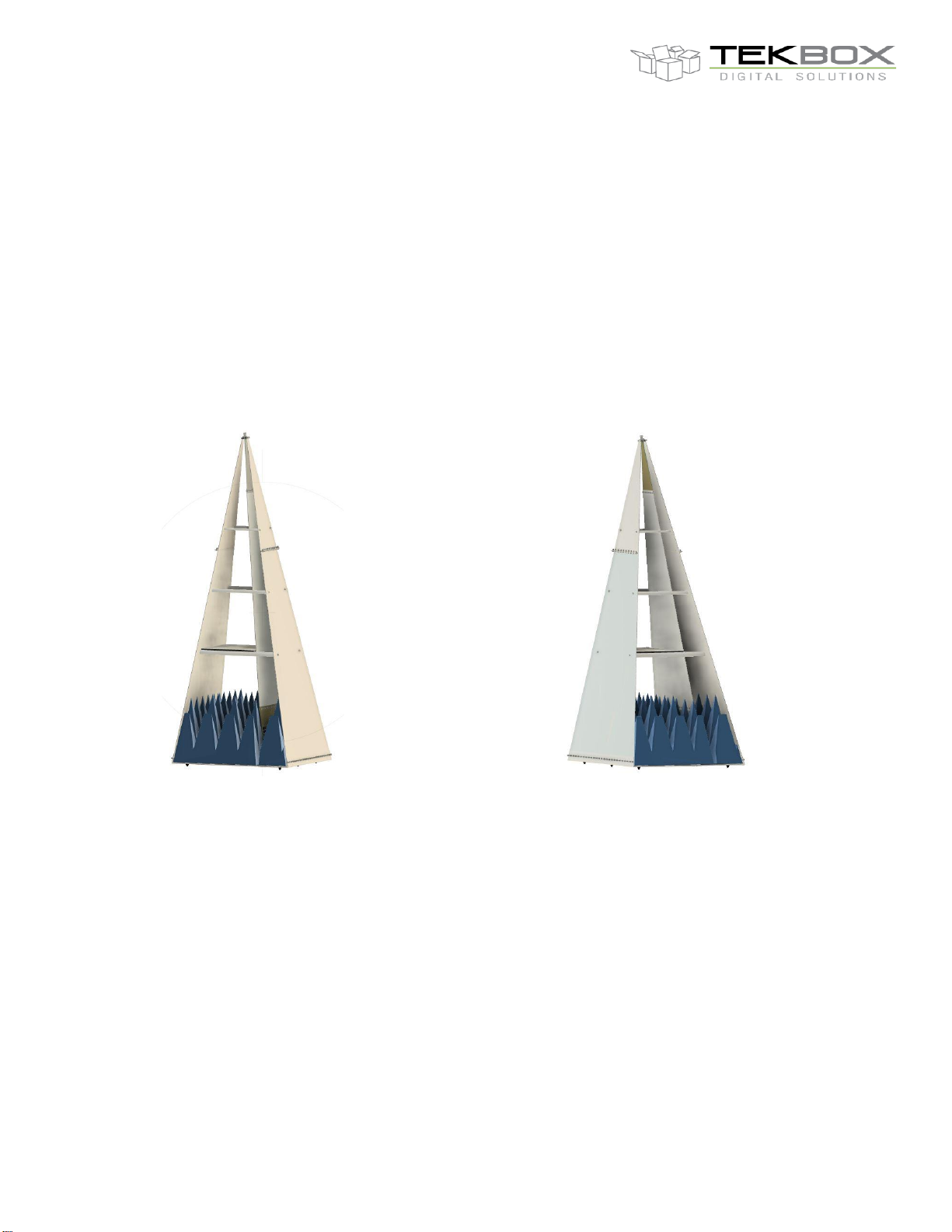
When positioned vertically, the TBGTC1 requires just an area of 78 cm × 52 cm. The EUT can be conveniently
placed on a supplied wooden board that rests on the GTEM-cell spacers.
2 GTEM cell
A GTEM cell is a tapered, hybrid terminated 50 ohm stripline device for radiated emissions and immunity testing
of electronic devices. It is not a replacement, but due to its size and cost it is a convenient alternative to
measurements in an anechoic chamber.
A GTEM cell consists of a septum, the conductive strip in the centre section and walls which are connected to
ground. The geometry is designed to present a 50Ω stripline. The device under test (DUT) is placed in between
the bottom wall and the septum.
The TBGTC1 is an “open GTEM cell” with no side walls for convenient placement of the DUT and a preferable
vertical configuration. It may pick up RF background noise, which however can be taken into account by doing a
measurement of the cell output signal before powering on the DUT or by placing the GTEM-cell in a shielded tent,
which is also available from Tekbox.
Page 2
V1.1
TBGTC1
OPEN GTEM CELL FOR EMC PRE-COMPLIANCE TESTING
2
3 Technical data
GTEM Cell TBGTC1
Septum Height: 250 mm at the location of the EUT-board
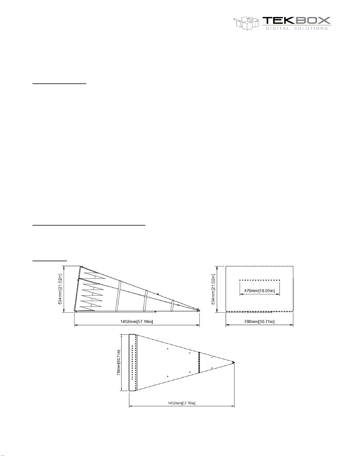
Outer dimensions (LxWxH): 1452x780x520 mm
Approx Cell Weight: 13 kg.
Maximum EUT size (LxWxH): 200x200x150 mm
Defined test volume (±3 dB < 3000 MHz, LxWxH): 100x100x100 mm
GTEM cell connectors: N-female
Nominal cell impedance: 50 Ohm
Frequency range: 0.009 MHz – 6 GHz
Wave impedance: 377 Ohm
Maximum continuous RF input power: 600W
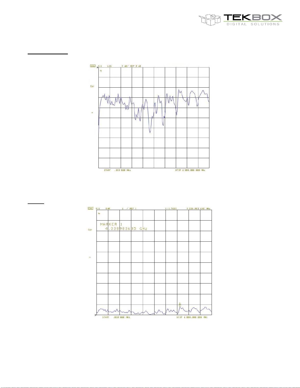
VSWR: 1:1.3 typical, 1:1.9 max.
Field uniformity on maximum test volume: up to 3 GHz < ± 6 dB
Optional shielded tent TBST-100/100/200:
Construction: two layers of conductive silver fabrics, access opening with conductive Velcro, aluminium frame
Ambient noise suppression: up to 50 dB in the range 10 MHz to 6 GHz
Dimensions:
Page 3
V1.1
TBGTC1
OPEN GTEM CELL FOR EMC PRE-COMPLIANCE TESTING
3
Input return loss:
TBGT1, input return loss, 30 kHz – 6 GHz
VSWR:
TBGT1, VSWR, 30 kHz – 6 GHz
Page 4
V1.1
TBGTC1
OPEN GTEM CELL FOR EMC PRE-COMPLIANCE TESTING
4
4 Application
4.1 Radiated emission tests:
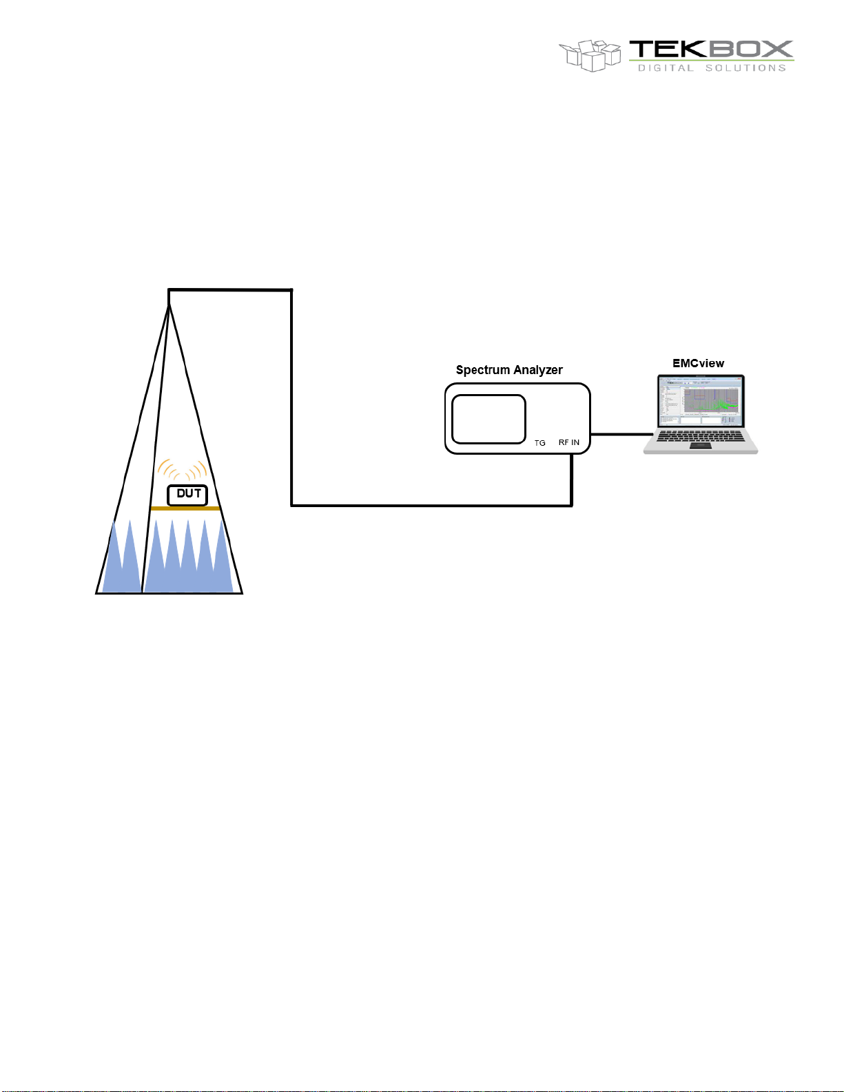
The septum of the GTEM-cell, similar to a broadband antenna, picks up radiated noise from the EUT and
presents it to the spectrum analyzer or a receiver input.
radiated emission measurement using the TBGTC1 GTEM-cell a spectrum analyzer and EMCview
It should be noted that radiated emission measurements in a GTEM-cell are near-field measurements. The
spectrum analyzer displays the result in dBµV, but the relevant standards specify emission limits as electricalfieldstrength in dBµV/m. It is a widespread misperception that the observed spectrum may easily be translated
into field strength, similar to how antenna factors are applied to antenna output voltage.
The GTEM-cell is typically used for relative measurements, tracking the EUT modifications with respect to the
radiated spectrum. IEC 61000-4-2 describes an algorithm that needs measuring the EUT in its three primary
orthogonal positions in order to correlate the measurement result with an OATS measurement. This algorithm is
built into our EMCview software. The IEC 61000-4-2 approach is explained in greater detail in the TEM-cell FAQ
document, which may be obtained from the Tekbox website.
When using this procedure, the EUT dimensions must not exceed one-third of the septum height. It should also
be noted that the results of an OATS measurement are not equivalent to the results of semi-anechoic chamber
measurements. Below 300 MHz, the correlation results are often lower than those of an OATS measurement. In
our experience, the correlation results in the region of 250 MHz - 1 GHz tend to be within ± 5dB of the results in
a semi-anechoic chamber. The correlation value is almost usually higher in the frequency band over 1 GHz
when compared to the measurement in the semi-anechoic chamber. If the results above 1 GHz pass the limits of
the standard, the unit will almost certainly pass in a semi-anechoic chamber.
Page 5
V1.1
TBGTC1
OPEN GTEM CELL FOR EMC PRE-COMPLIANCE TESTING
5
4.2 Radiated immunity tests:
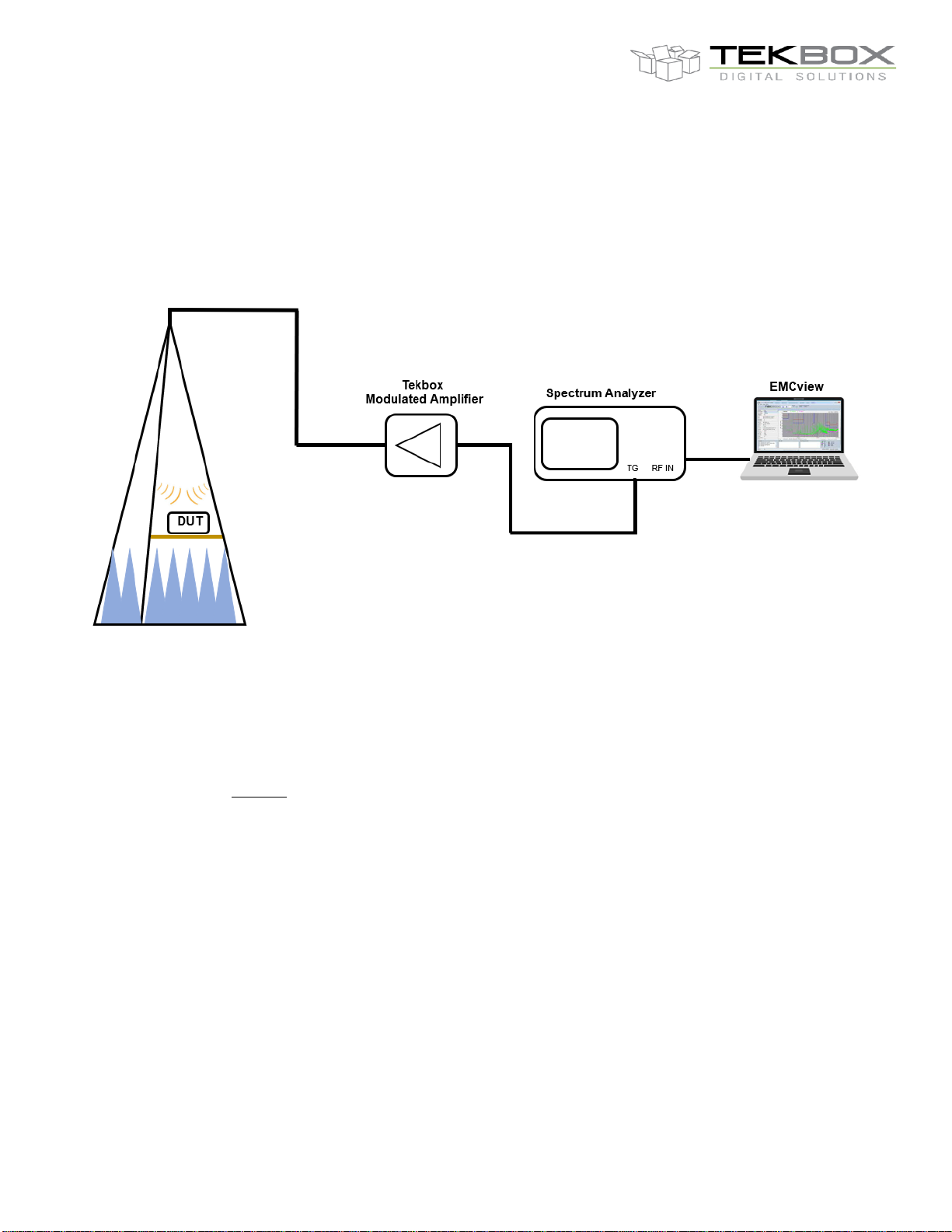
The GTEM-cell will be connected to the output of a RF amplifier driven by a swept signal generator or spectrum
analyzer tracking generator. The septum radiates the RF signal into the DUT. Typically, the RF signal is amplitude
or pulse modulated.
radiated emission measurement using the TBGTC1 GTEM-cell, a Tekbox modulated RF power amplifier, spectrum analyzer
tracking generator and EMCview
For calculating the required RF power for generating a given electric field strength between septum and lower wall
of the TBGTC1, we need to use the following formula:
𝑷𝒐𝒘𝒆𝒓 𝑹𝒆𝒒𝒖𝒊𝒓𝒆𝒅 =
(
𝑬 ∗ 𝒅
)
𝟐
𝒁
∗ 𝑭𝒍𝒂𝒕𝒏𝒆𝒔𝒔 ∗ 𝑴𝒐𝒅𝒖𝒍𝒂𝒕𝒊𝒐𝒏 𝑨𝒍𝒍𝒐𝒘𝒂𝒏𝒄𝒆
Where E is the RMS electric field and d is the septum height
Z is the GTEM cell characteristic impedance =50 Ω
Modulation allowance = 3.24 ( For 80% Amplitude Modulation)
Modulation allowance =1 ( For non-modulated , CW )
Flatness = 2 (For 3 dB of flatness)
Assuming the DUT is placed in the center of the cell and in the middle between bottom wall and septum, we can
however use the simplified formula for calculating the theoretical maximum field strength.
d = 10 cm E = (√(P*50Ω))*10
d = 15 cm E = (√(P*50Ω))*6.66
d = 20 cm E = (√(P*50Ω))*5
d = 25 cm E = (√(P*50Ω))*4
Page 6
V1.1
TBGTC1
OPEN GTEM CELL FOR EMC PRE-COMPLIANCE TESTING
6
TBGTC1 , applied RF power
Maximum field strength between septum and wall
10W (40 dBm)
112 V/m
1 W (30 dBm)
35 V/m
0.1 W (20 dBm)
11 V/m
0.01 W (10dBm)
4 V/m
TBGTC1, field strength vs. RF power for d=200 mm
TBGTC1 , applied RF power
Maximum field strength between septum and wall
10W (40 dBm)
89 V/m
1 W (30 dBm)
28 V/m
0.1 W (20 dBm)
9 V/m
0.01 W (10dBm)
3 V/m
TBGTC1, field strength vs. RF power for d=250 mm
Tekbox provides a selection of modulated RF power amplifiers for low-cost immunity testing setups. These
amplifiers include built-in modulators to generate the needed modulation forms and can thus be powered by the
spectrum analyzer's tracking generator output. As a result, there is no need to purchase an RF signal generator.
The spectrum analyzer tracking generator may be easily controlled using Tekbox's EMCview software.
Depending on the modulated RF power amplifier used and the septum height of the GTEM cell at the position of
the EUT, this setup can create fieldstrengths of several hundred volts per metre. Refer to the datasheets of the
modulated amplifiers for additional information.
The electric field is orthogonally aligned to the septum. To establish a worst-case situation for the EUT, position it
within the TEM cell with the PCB traces orthogonally to the Septum, exposing it to the highest field gradient. If the
EUT's dimensions allow for installation in all three orthogonal directions, the EUT must be placed and tested in all
three orientations.
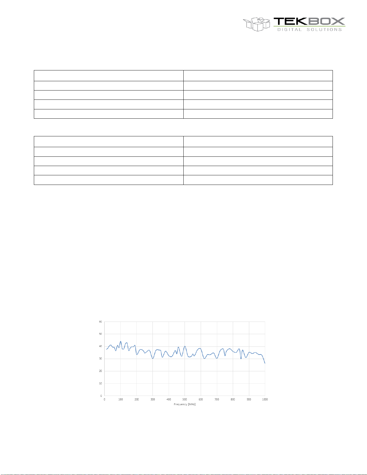
The field uniformity test is performed according to IEC 61000-4-20 standard for a 9-point calibration grid with the
size of 200 mm x 200 mm at the septum height of 250 mm. Figure 7 shows the variation of the electric field vs
frequency at the center point of the test volume for a given 5W constant forward power.
TBGTC1, electric field versus frequency
Page 7
V1.1
TBGTC1
OPEN GTEM CELL FOR EMC PRE-COMPLIANCE TESTING
7
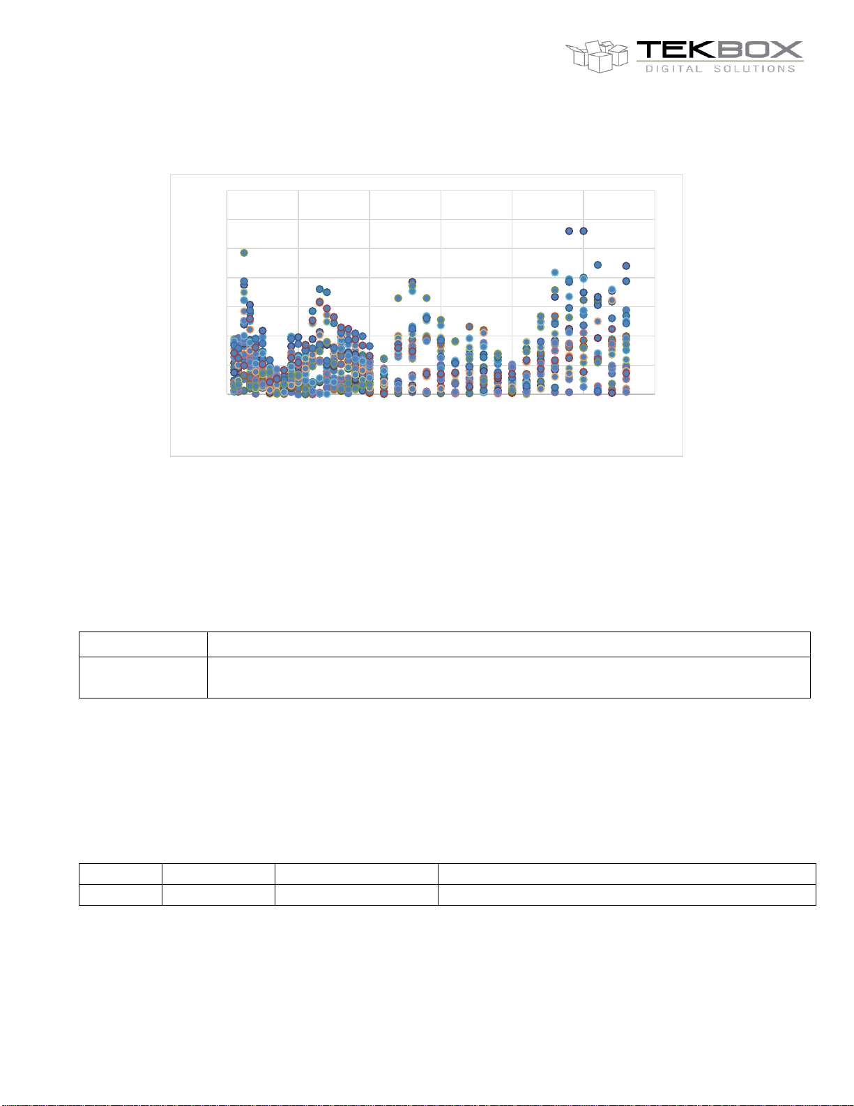
Also, the maximum difference in electric field components for 7 out of 9 points of the calibration grid is shown in
figure 8.
TBGTC1, field uniformity test on a 9-point, 200 mm x 200 mm grid
The GTEM-cell E-field uniformity for at least four out of five calibration points is within the 6 dB criterion for
frequencies up to 3 GHz.
5 Ordering Information
Part Number
Description
TBGTC1
Open GTEM cell, 250mm maximum septum height, Pyramidal foam absorbers 500 MHz - 40
GHz, N-Male to N-Male coaxial cable
Ordering Information
In order to reduce shipment cost, the GTEM-cell comes disassembled. An assembly instruction document and the
necessary tools are added.
6 History
Version
Date
Author
Changes
V1.0
07.06.2023
Mayerhofer
Creation of the document
History
0
1
2
3
4
5
6
7
0 500 1000 1500 2000 2500 3000
Difference [dB]
Frequency [MHz]
 Loading...