

Page 1
V1.2
1
TBCDN-M3
`
Coupling Decoupling Networks (CDN)
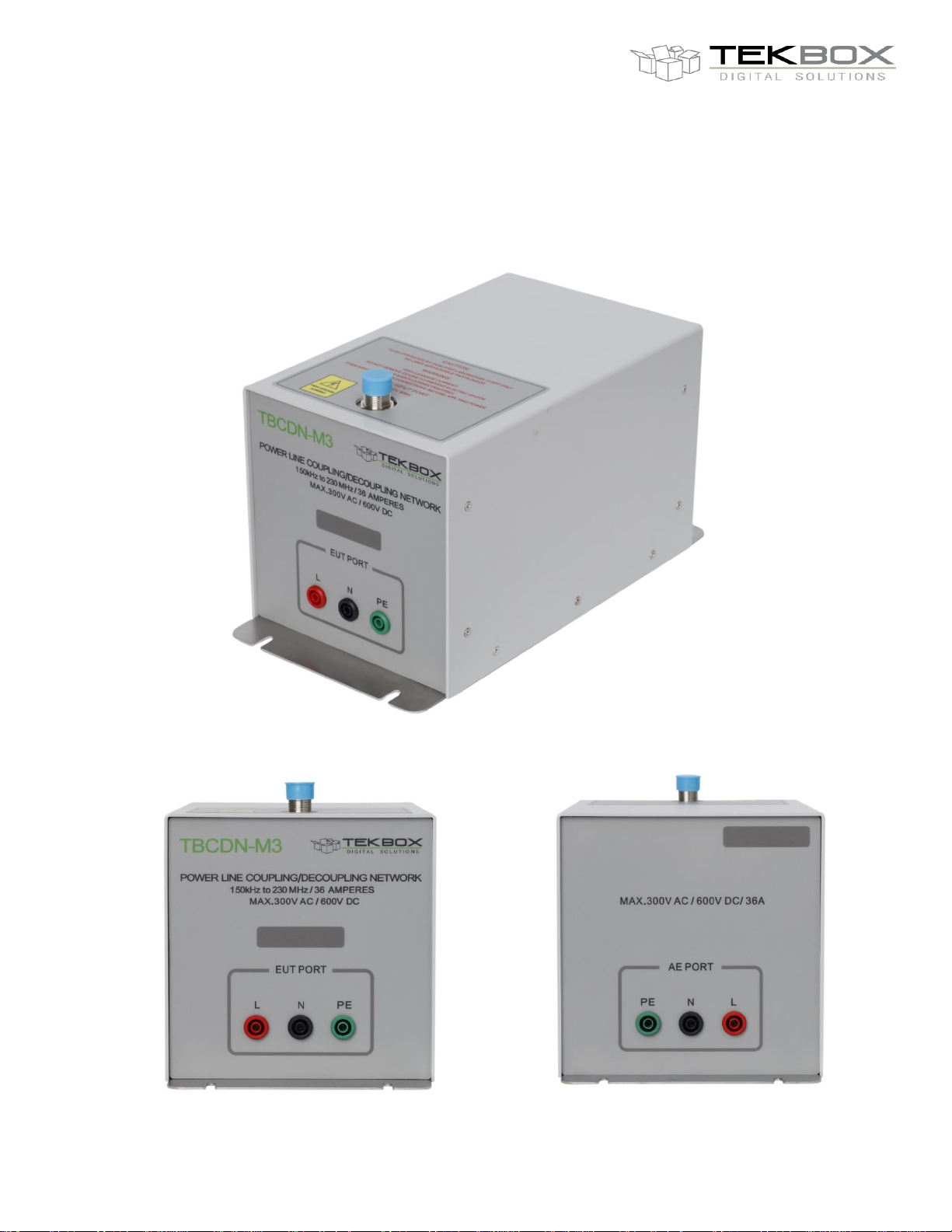
The TBCDN-M3 is a Coupling Decoupling Network for conducted immunity testing according to IEC 61000-4-6.
The TBCDN-M3 is compliant with IEC 61000-4-6 Annex D2. It is designed to inject common mode disturbance
signals in the frequency range from 150 kHz to 230 MHz into unscreened AC and DC power supply lines.
Page 2
V1.2
2
TBCDN-M3
`
Coupling Decoupling Networks (CDN)
1 Specifications
Maximum supply voltage: 300V AC, 600V DC
Maximum current: 36A
Frequency range: 150 kHz – 230 MHz
Maximum RF input power: 6.5W CW
Maximum RF input voltage: 32 V
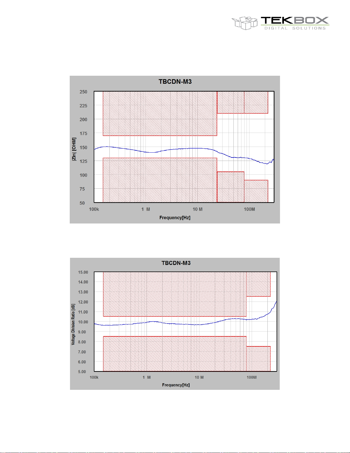
Common mode impedance: 150 kHz – 24 MHz: 150 Ω ± 20 Ω
24 MHz – 80 MHz: 150 Ω + 60 Ω / - 45 Ω
80 MHz – 230 MHz: 150 Ω ± 60 Ω
Voltage Division Ratio: 150 kHz – 80 MHz: 9.5 dB ± 1 dB
80 MHz – 230 MHz: 9.5 dB + 3 dB / - 2 dB
RF input connector: N – female
EUT / AE connectors: 4 mm banana safety jacks, 4mm slots in base plate for GND connection
Housing material: powder coated aluminium, stainless steel base plate
Dimensions: 300 x 150 x 150 mm
Weight: ca. 2.5 kg
Included: individual test protocol with voltage division ratio and common mode impedance
Optional accessories: 30mm adapter panel with shorting bars and BNC connector
50 Ω to 150 Ω N-male to N-female adapter
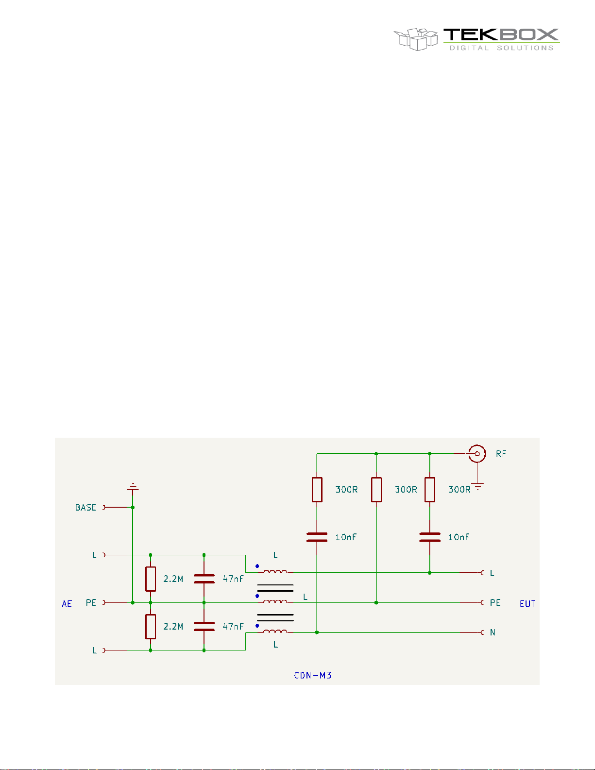
2 Informative schematic
Page 3
V1.2
3
TBCDN-M3
`
Coupling Decoupling Networks (CDN)
3 Typ. EUT common mode impedance
4 Typ. Voltage Division Ratio
Page 4
V1.2
4
TBCDN-M3
`
Coupling Decoupling Networks (CDN)
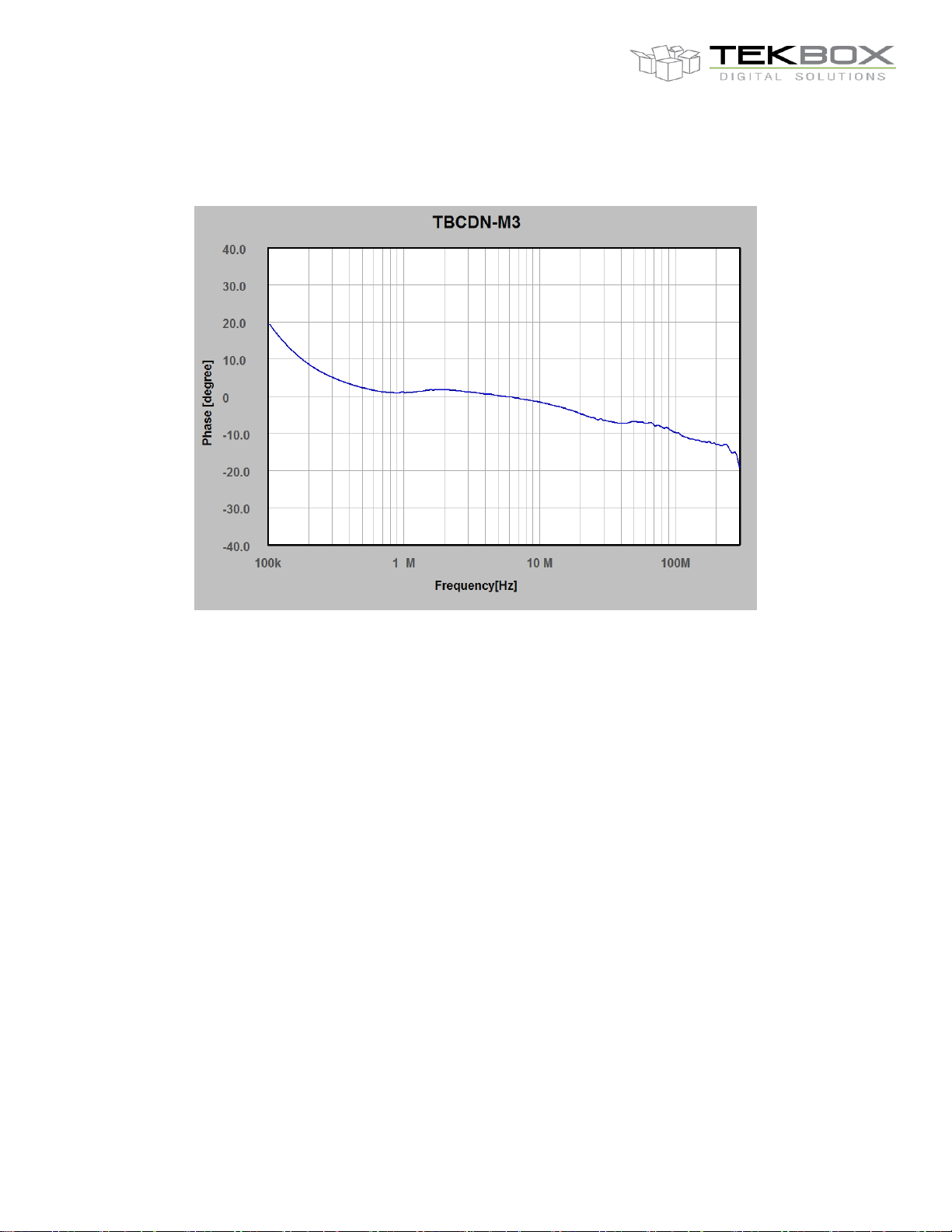
5 EUT Input Phase (common mode, informative)
6 Introduction
Similar as LISNs being the central components for conducted emission testing, CDNs are essential for
conducted immunity test set ups. CDNs are used to couple RF into cables.
Whereas the CISPR standards specify conducted emission measurements, IEC 61000-4-6 is the main standard
for conducted immunity testing. IEC 61000-4-6 specifies three coupling devices:
Coupling Decoupling Networks (CDN)
Coupling via CDN is the most common test method. It requires least power. It is always used, when
appropriate CDNs for the type of signal are available.
EM Clamps
The EM-Clamp is used, when a CDN is not possible, e.g. for shielded or complex cables. The clamp and
the separate decoupling clamp are placed around the cable.
Bulk current injection clamps
Similar use as EM-clamp. A monitoring of the injected current is strongly recommended.
Coupling and decoupling devices shall be used for appropriate coupling of the disturbing signal (over the entire
frequency range, with a defined common mode impedance at the EUT port to the various cables connected to
the EUT and for preventing applied test signals from affecting other devices, equipment and systems that are not
under test.
The preferred coupling and decoupling devices are the CDNs, for reasons of test reproducibility and protection
of the AE. Furthermore, CDNs require significantly lower RF power, to achieve the same test levels, compared to
EM clamps or BCI clamps. The main coupling and decoupling device parameter, the common mode impedance
seen at the EUT port, is specified in the table below:
Page 5
V1.2
5
Frequency band
Parameter
150 kHz – 24 MHz
24 MHz – 80 MHz
80 MHz – 230 MHz
ǀ Common mode impedance ǀ
150 Ω ± 20 Ω
150 Ω + 60 Ω / - 45 Ω
150 Ω ± 60 Ω
Line type
Examples
CDN - type
Power supply (AC and DC) and
earth connection
AC mains
DC in industrial installations
Earth connection
CDN - Mx
Screened cables
Coaxial cables
cables used for LAN and USB
connections
cables for audio systems
CDN - Sx
Unscreened balanced lines
ISDN lines
telephone lines
CDN - Tx
Unscreened unbalanced lines
Any line not belonging to other
groups
CDN – Afx or CDN - Mx
TBCDN-M3
`
Usage of CDNs:
Coupling Decoupling Networks (CDN)
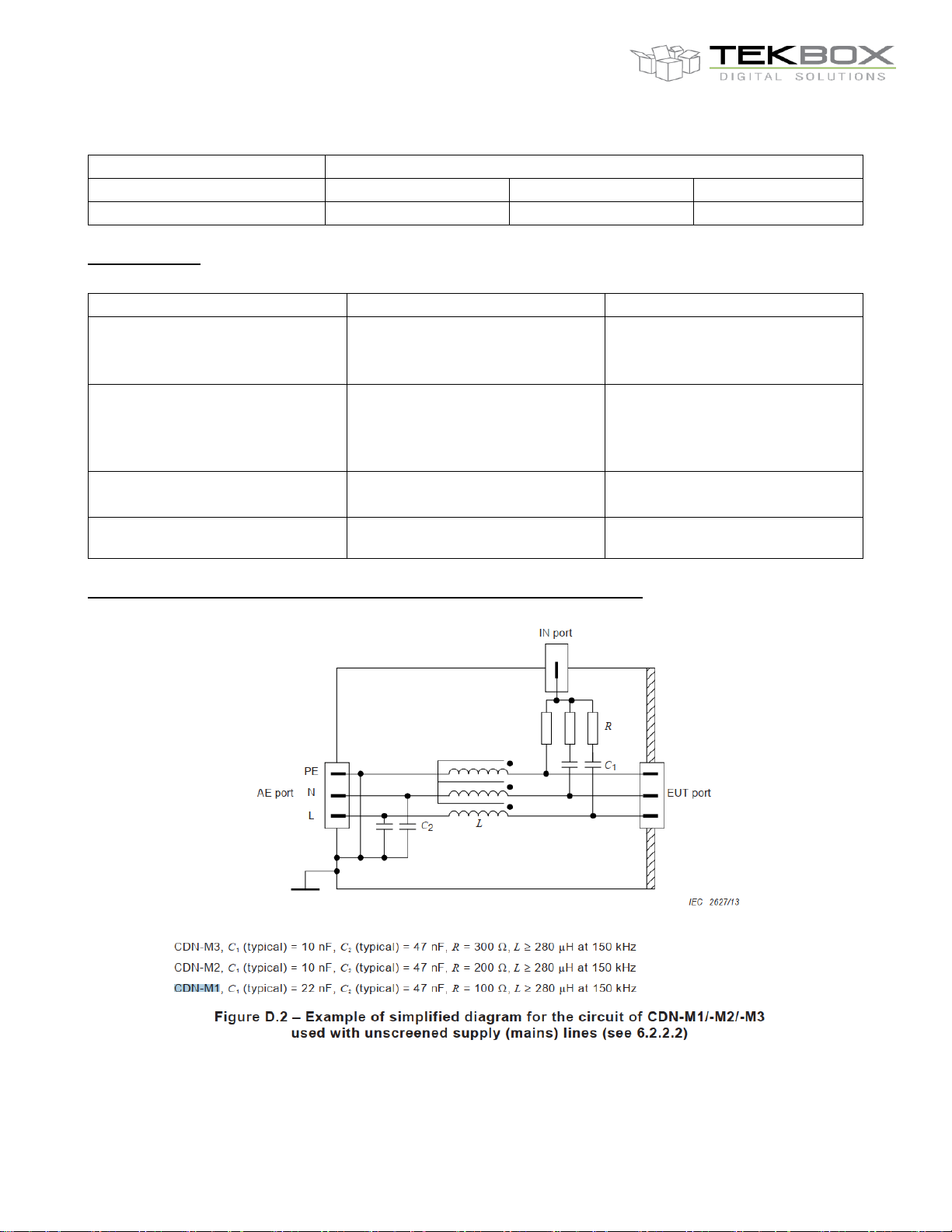
Coupling Decoupling network according to IEC 61000-4-6, example M1, M2, M3:
Page 6
V1.2
6
Level
Voltage level (e.m.f.)
U0 [V]
U0 [dBµV]
1 1 120 2 3
129.5
3
10
140
X*
Special
* ”X” can be any level, above, below or in between the others. The level has to be specified in the dedicated equipment specification
TBCDN-M3
`
Coupling Decoupling Networks (CDN)
The performance of the CDN shall not be unduly degraded by saturation of the magnetic material due to current
drawn by the EUT. Wherever possible, the network construction should ensure that the magnetising effect of the
forward current is cancelled by that due to the return current.
If in actual installations the supply wires are individually routed, separate CDN-M1 CDNs shall be used. All input
ports shall be treated separately. If the EUT is provided with functional earth terminals (e.g. for RF purposes or
high leakage currents), they shall be connected to the reference ground plane:
– through the CDN-M1 when the characteristics or specification of the EUT permits. In this case, the (power)
supply shall be provided through an appropriate CDN-Mx type network;
– when the characteristics or specification of the EUT do not permit the presence of a CDN-M1 network in series
with the earth terminal for RF or other reasons, the earth terminal shall be directly connected to the reference
ground plane. In this case the CDN-M3 network shall be replaced by a CDN-M2 network to prevent an RF shortcircuit by the protective earth conductor. When the equipment was already supplied via CDN-M1 or
CDN-M2 networks, these shall remain in operation;
– for a 3-phase supply, a similar adjustment needs to be done regarding the use of an appropriate CDN-Mx type
network.
Warning: The capacitors used within the CDNs bridge live parts. As a result, high leakage currents may occur
and safety connections from the CDN to the reference ground plane are mandatory.
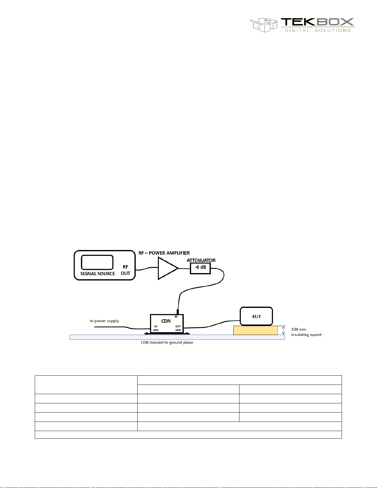
7 Immunity test set up
The picture below shows a basic conducted immunity test set up. The purpose of the 6 dB attenuator is
improved impedance matching between RF power amplifier and CDN:
Following test levels are specified:
Page 7
V1.2
7
Level
unmodulated
rms voltage
modulated
rms voltage
unmodulated RF
power
modulated RF power
Including 6 dB
attenuator
1
1 V
1.8 V
20 mW / 13 dBm
64.8 mW / 18.1 dBm
257 mW / 24.1 dBm
2
3 V
5.4 V
180 mW / 22.6 dBm
589 mW / 27.7 dBm
2.34 W / 33.7 dBm
3
10 V
18 V
2 W / 33 dBm
6.48 W / 38.1 dBm
25.7 W / 44.1 dBm
Transducer type
Required output power from RF amplifier
CDN
7 W
BCI - clamp
176 W
EM - clamp
28 W
TBCDN-M3
`
Coupling Decoupling Networks (CDN)
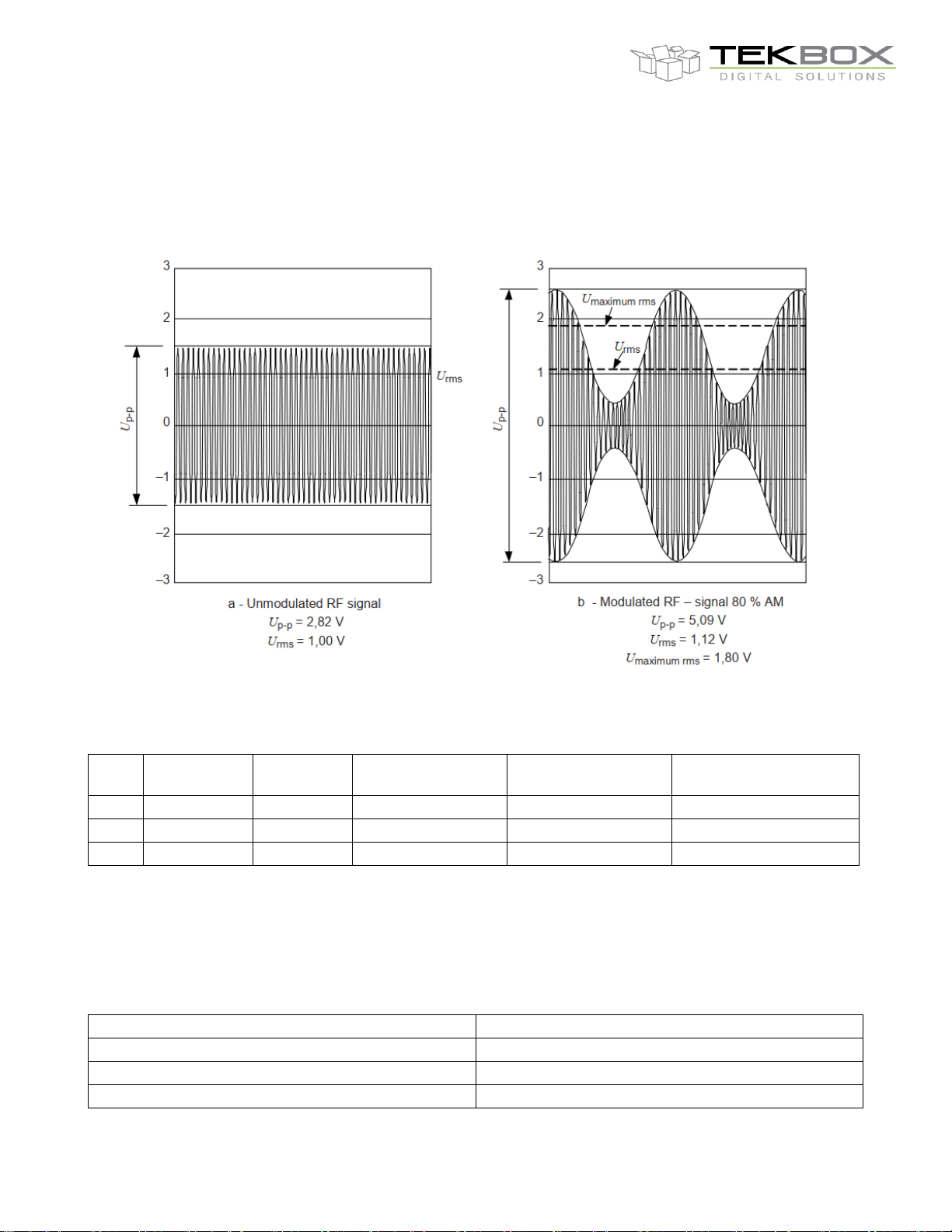
The test levels are set at the EUT port of the coupling devices. For testing of the equipment, this signal is 80 %
amplitude modulated with a 1 kHz sine wave to simulate actual threats. The effective amplitude modulation is
shown below:
Consequently, the level of the modulated signal must be 5.1 dB higher than the test levels specified by the
standard. Adding a 6dB attenuator to improve matching of the RF power amplifiers would require following amplifier
output power:
The standard test frequency range is 150 kHz – 80 MHz, with certain device classes being tested from 150 kHz –
230 MHz.
The table below shows a comparison of the required power for level 3, using different coupling methods. These
power levels do not consider any 6 dB attenuator.
Page 8
V1.2
8
TBCDN-M3
`
Coupling Decoupling Networks (CDN)
8 Calibration
Frequency range:
Although the requirements in the standard are specified for the frequency range 150 kHz up to 80 MHz, the
applicable frequency range depends on the normal installation and operation conditions of the equipment to be
tested. In general, the stop frequency will be 80 MHz. In some cases, where small-sized equipment is
considered (dimension < λ/4), dedicated product standards may prescribe that the stop frequency is extended up
to a maximum of 230 MHz. When using this test method up to higher frequencies, results are influenced by: the
size of equipment, the type(s) of interconnecting cables used, and the availability of special CDNs, etc. Further
guidance for proper application should be supplied in the dedicated product standards.
On the other hand, NAMUR NE 21 extends the applicable frequency down to 10 kHz.
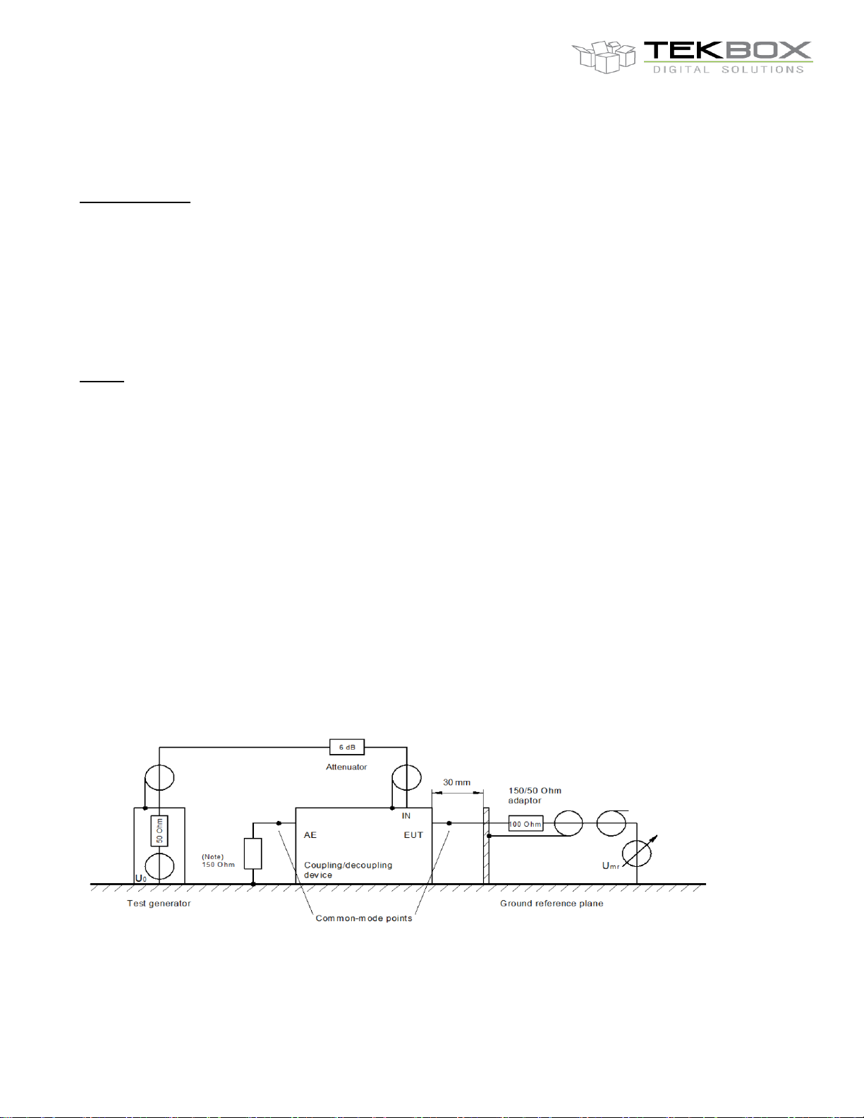
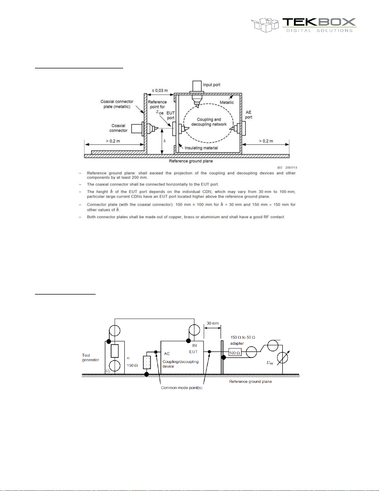
Set up:
• The test generator (RF out) shall be connected via the 6 dB-attenuator to the RF input port of the CDN.
• The EUT port of the CDN shall be connected in common mode via a 150 Ω to 50 Ω adapter to a measuring
equipment having a 50 Ω input impedance.
• The AE-port shall be loaded in common mode with a 150 Ω to 50 Ω adapter, terminated with 50 Ω.
The assembly is outlined below.
With direct injection to screened cable (CDN-S types), the 150 Ω load at the AE-port is not required as the
screen will be connected to the ground reference plane at the AE-port side.
With the CDN M-types, CDN AF-types and CDN T-types the 150 Ω connector is according to standard
prescribed, yet the calibration values for these CDN types are virtually independent of the load. This is because
these types have capacitors against ground at the AE-port side, which generate a RF-short circuit, comparable
to those of the S-types.
Thus with the CDN M-types, CDN AF-types and CDN T-types the load of 150 Ω at the auxiliary equipment
connector can be dispensed with.
In order to calibrate a CDN you require:
• specific calibration adapters
• ground plane exceeding the length of the CDN 20 cm on each side
• 150 Ω to 50 Ω adapters
Page 9
V1.2
9
TBCDN-M3
`
Coupling Decoupling Networks (CDN)
CDN common mode impedance
measurement set up:
The input port is terminated with 50 Ω. The impedance requirement shall be met with the AE port open or
shorted to ground.
CDN common mode impedance values:
150 kHz – 24 MHz: 150 Ω ±20 Ω
24 MHz – 80 MHz: 150 Ω +60 Ω /-45 Ω
80 MHz – 230 MHz: 150 Ω ±60 Ω
Voltage division factor
Measurement set up:
Voltage division factor RF-port to EUT-port:
150 kHz – 80 MHz: 9.5 dB ± 1dB
80 MHz – 230 MHz: 9.5 dB +3 dB / - 2 dB
Page 10
V1.2
10
Part Number
Description
TBCDN-M3
M3 coupling decoupling network
TBCDN-M3-AP
Adapter panel with shorting bar for M3 coupling decoupling network
TBCDN-50-150
50 Ω to 150 Ω N-male to N-female adapter
Version
Date
Author
Changes
V1.0
24.3.2022
Mayerhofer
Creation of the document
V1.1
13.6.2022
Mayerhofer
Typo correction in chapter 9
V1.2
14.6.2022
Mayerhofer
correction in chapter 2
TBCDN-M3
`
Coupling Decoupling Networks (CDN)
9 Ordering Information
10 History
 Loading...