

Page 1
V1.9
1
H20, H10, H5, E5, TBWA2/20dB, TBWA2/40dB
EMC Near-field Probes + Wideband Amplifier
1 Introduction
The H20, H10, H5 and E5 are magnetic field (H) and electric field (E) probes for radiated emissions EMC precompliance measurements. The probes are used in the near field of sources of electromagnetic radiation.
They serve to locate and identify potential sources of interference within the building blocks of electronic
assemblies.
The probes act similar as wide bandwidth antennas, picking up radiated emissions from components, PCB traces,
housing openings or gaps and from any other parts that could be emitting RF. The probes are usually connected
to a spectrum analyser. Scanning the probe over the surface of a PCB assembly or housing quickly identifies
locations which emit electromagnetic radiation. By changing to a probe with smaller size, the origination of the
emissions can be further narrowed down.
Additional applications are RF immunity tests by feeding a RF signal into the probe and radiating it into
potentially susceptible circuit sections: Furthermore the probes can be used in the field of repair or debugging to
track down issues in RF signal chains by contactless measurement of RF signal levels. One more application is
non- invasive measurement of RF building blocks such as modulators or oscillators. Frequency, phase noise and
spectral components can be measured in conjunction with a low noise preamplifier.
The TBWA2/20dB and TBWA2/40db wideband amplifiers are connected between EMC probe and Spectrum
Analyzer to increase the dynamic range of the measurements.
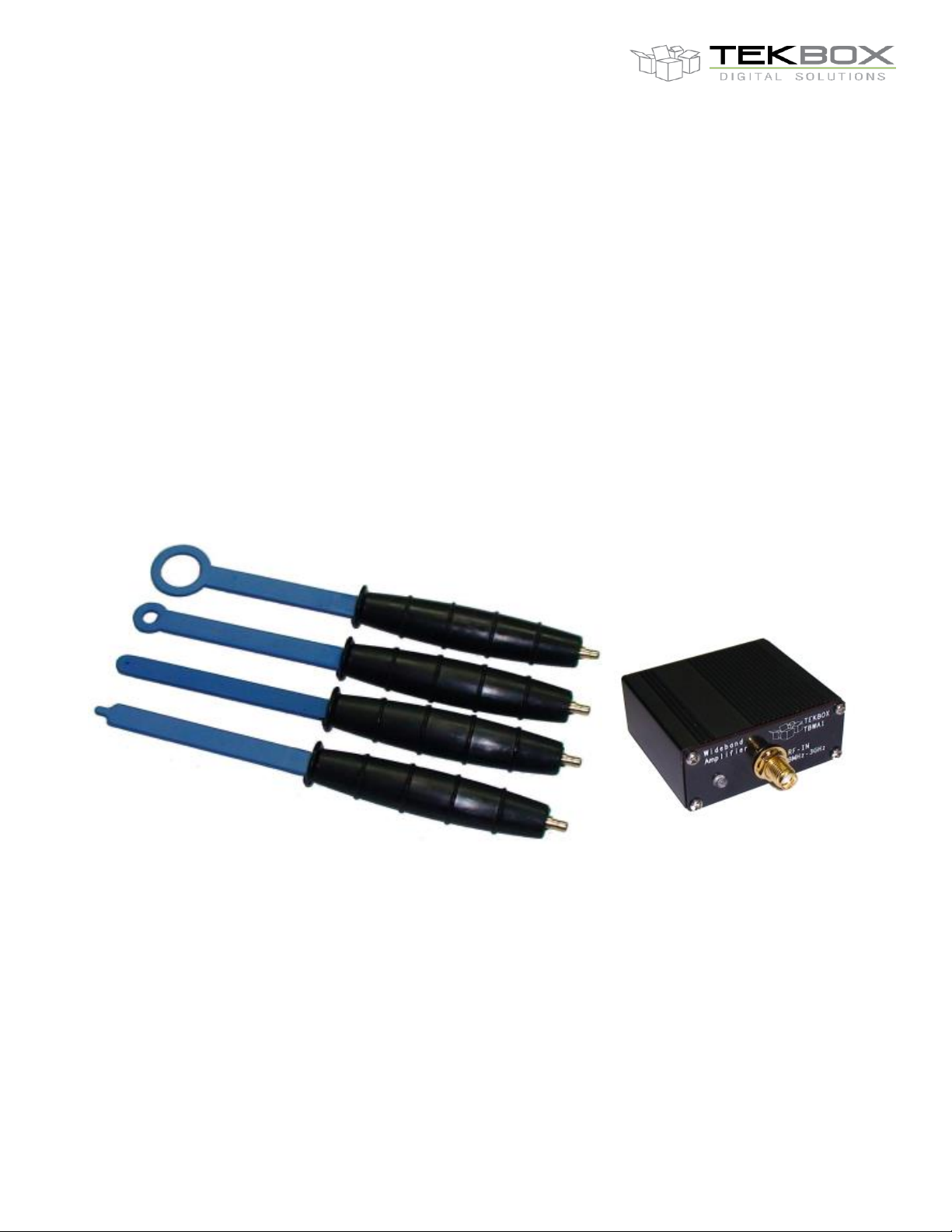
Picture 1 – from top, H20, H10, H5, E5; wideband amplifier
2 Features
Slim design for good access in between tightly spaced components
Shielded loops to avoid picking up common mode noise; insensitive to the human hand
Frequency range: up to 6GHz, see coupling plots of the respective probes
SMB connectors to avoid twisting the RF cable when scanning DUTs
Page 2
V1.9
2
Probe
length
loop
tip
H20 H-Field
170 mm
20 mm
n.a.
H10 H-Field
170 mm
10 mm
n.a.
H5 H-Field
170 mm
5 mm
n.a.
E5 E-Field
170 mm
n.a.
5 mm
-90
-80
-70
-60
-50
-40
-30
-20
-10
0
10
0.1 1 10 100 1000 10000
H-FIELD PROBES
output power versus frequency at 1µT
H20
H10
H5
Frequency [MHz]
output power [dBm]
H20, H10, H5, E5, TBWA2/20dB, TBWA2/40dB
EMC Near-field Probes + Wideband Amplifier
Insulated with rubber coating
Wideband amplifiers with 20dB and 40dB gain
3 Dimensions
Wideband amplifiers:
TBWA2/20dB: 48 mm x 63mm x 20mm TBWA2/40dB: 48 mm x 63mm x 20mm
4 Frequency Response
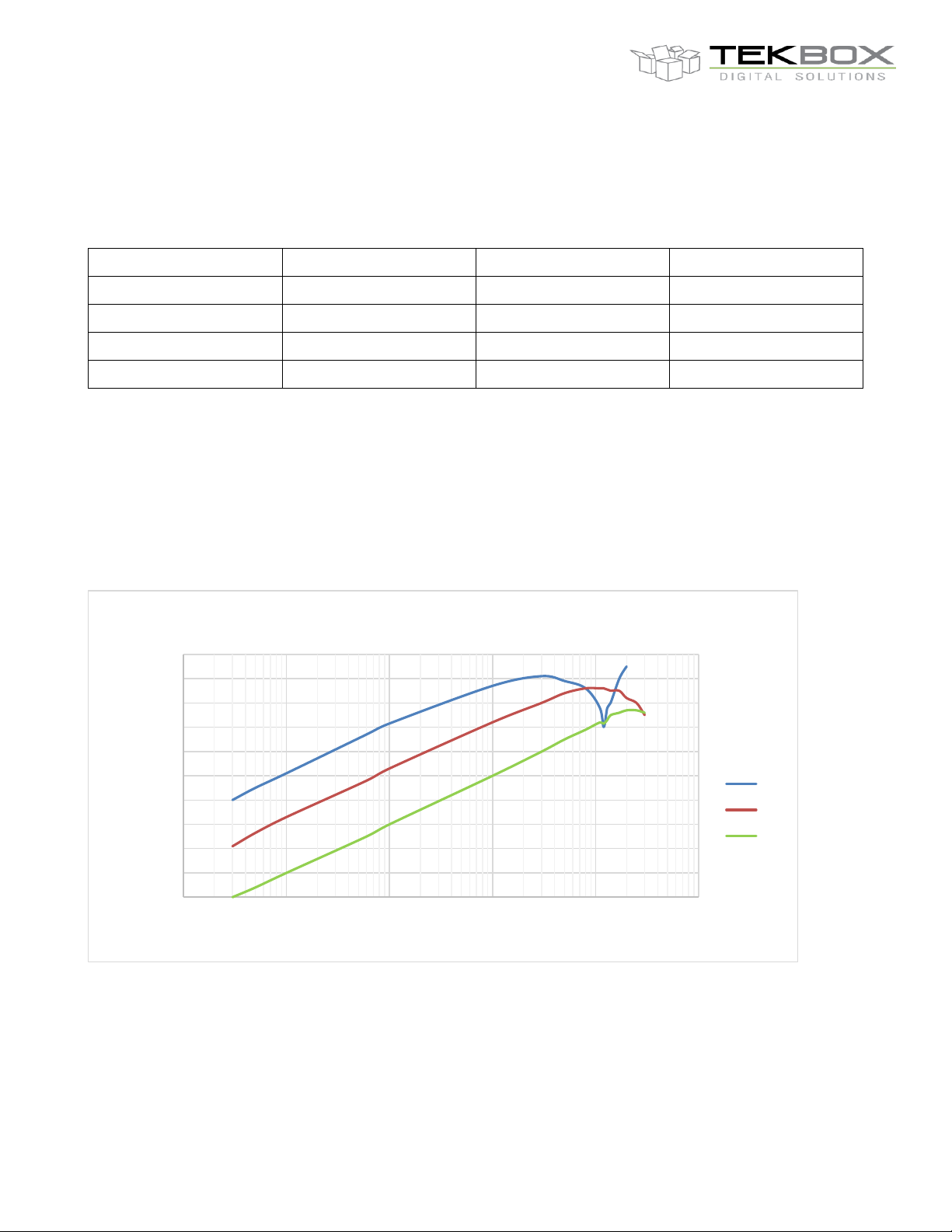
Picture 2 – frequency response, H-field probes
Page 3
V1.9
3
-120
-110
-100
-90
-80
-70
-60
-50
-40
0.1 1 10 100 1000 10000
E-FIELD PROBE
output power versus frequency at 1V/m
E5
H20, H10, H5, E5, TBWA2/20dB, TBWA2/40dB
EMC Near-field Probes + Wideband Amplifier
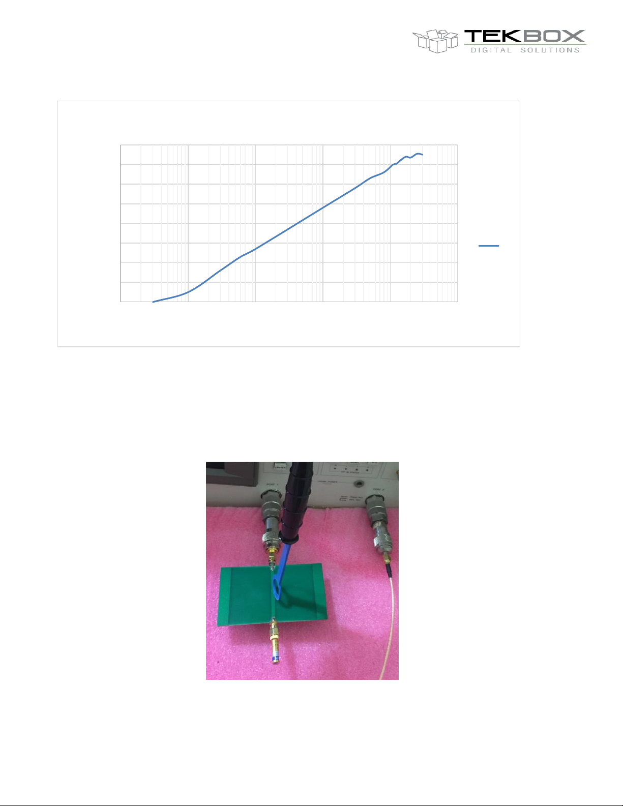
Picture 3 – frequency response, E-field probe
5 Coupling loss
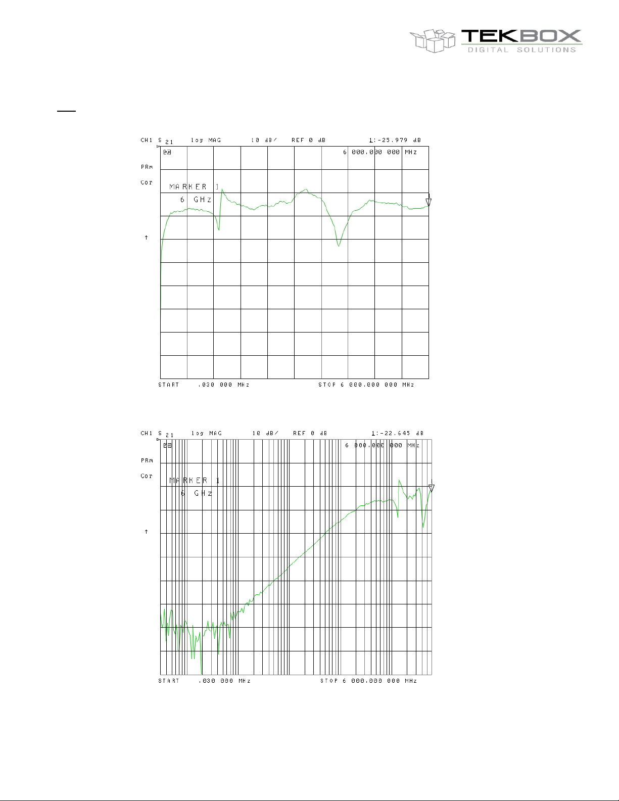
Coupling loss was measured on a terminated 50 Ohm stripline on a 1.6mm thickness FR4 board using a vector
network analyzer.
Picture 4 – measurement setup for coupling loss, 30kHz – 6GHz
Page 4
V1.9
4
H20, H10, H5, E5, TBWA2/20dB, TBWA2/40dB
EMC Near-field Probes + Wideband Amplifier
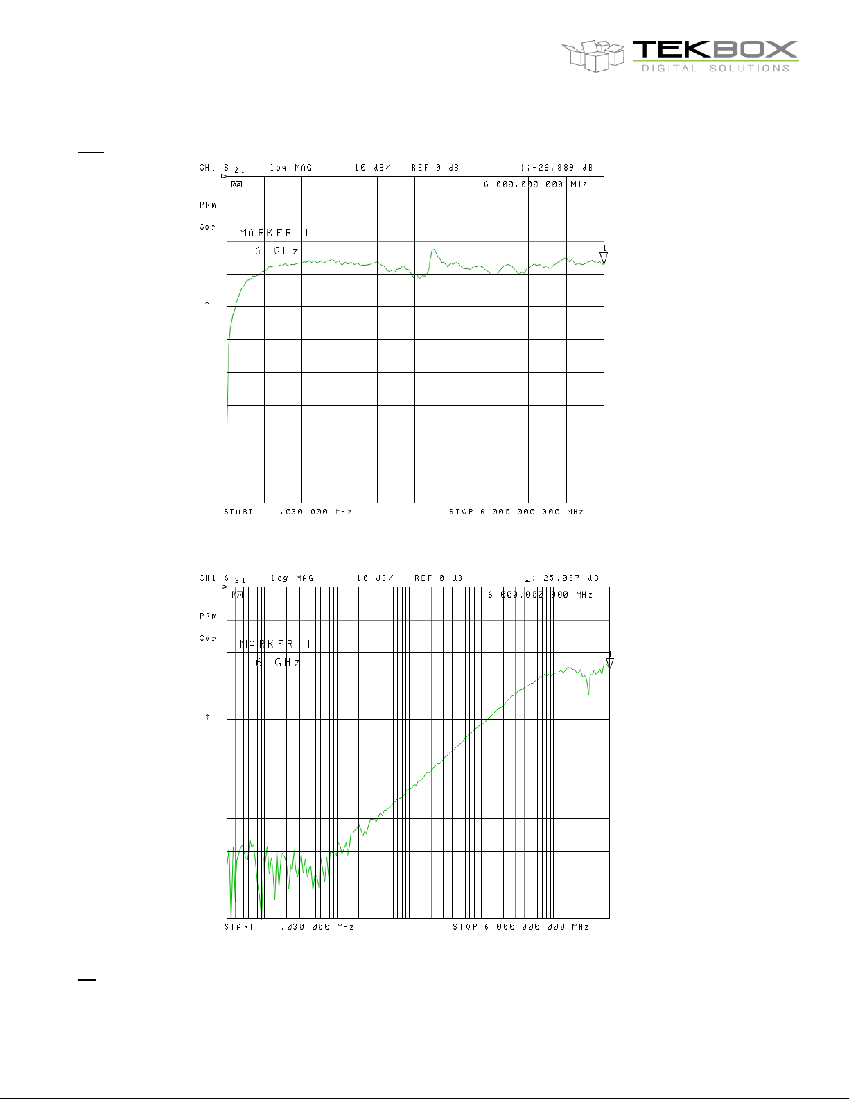
H20
Picture 5 – H20, coupling loss, 30 kHz – 6 GHz, lin.
Picture 6 – H20, coupling loss, 30 kHz – 6 GHz, log.
Page 5
V1.9
5
H20, H10, H5, E5, TBWA2/20dB, TBWA2/40dB
EMC Near-field Probes + Wideband Amplifier
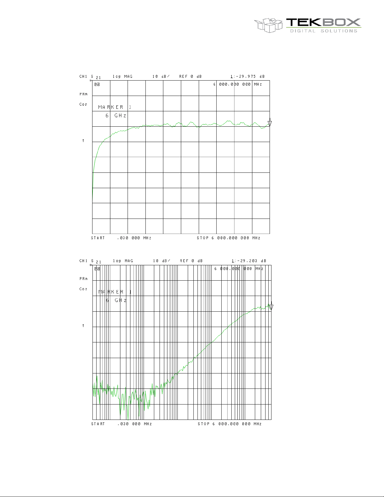
H10
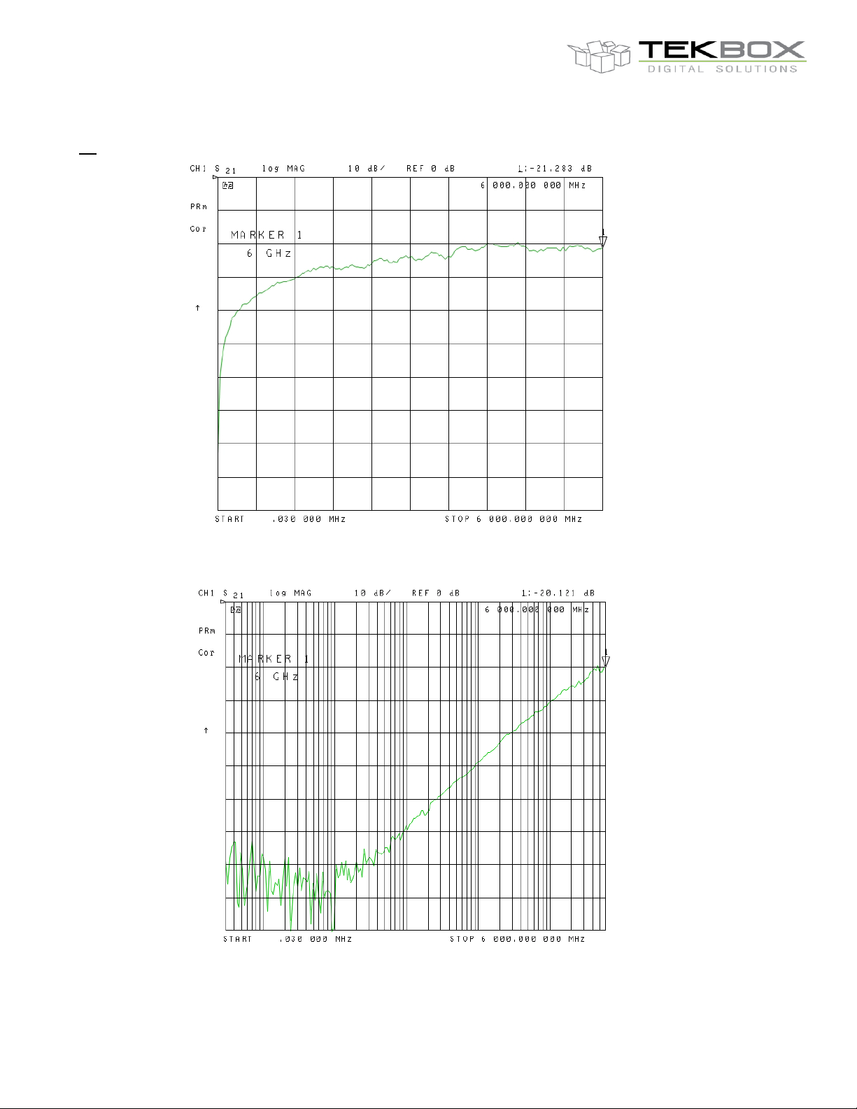
H5
Picture 7 – H10, coupling loss, 30 kHz – 6 GHz, lin.
Picture 8 – H10, coupling loss, 30 kHz – 6 GHz, log.
Page 6
V1.9
6
H20, H10, H5, E5, TBWA2/20dB, TBWA2/40dB
EMC Near-field Probes + Wideband Amplifier
Picture 9 – H5, coupling loss, 30 kHz – 6 GHz
Picture 10 – H5, coupling loss, 30 kHz – 6 GHz, log.
Page 7
V1.9
7
H20, H10, H5, E5, TBWA2/20dB, TBWA2/40dB
EMC Near-field Probes + Wideband Amplifier
E5
Picture 11 – E5, coupling loss, 30 kHz – 6 GHz, lin.
Picture 12 – E5, coupling loss, 30 kHz – 6 GHz, log.
Page 8
V1.9
8
1 MHz
10 MHz
100 MHz
500 MHz
1 GHz
2 GHz
3 GHz
4.5 GHz
6 GHz
14.8 dB
20.2 dB
20.2 dB
20 dB
19.8 dB
19 dB
17.6 dB
17.4 dB
15.4 dB
H20, H10, H5, E5, TBWA2/20dB, TBWA2/40dB
EMC Near-field Probes + Wideband Amplifier
5.1 Summary:
The larger the tip diameter, the lower the coupling loss at frequencies below 1GHz. At frequencies above 1GHz,
the performance in terms of coupling loss of all probes is similar. The H20 has resonances in the range of 1.3GHz
and 4GHz. The H10 has a resonance at 3.1GHz.
The smaller the loop, the better the spatial response.
6 Wideband Amplifiers
6.1 TBWA2/20dB
Technical Data:
Input: 50 Ohm, SMA
Output: 50 Ohm, SMA
Nominal supply Voltage: 4.5 - 5V, typ. 110mA, Mini-USB-B connector
Maximum supply voltage: 5.5V
Maximum input power: +10dBm
1dB output compression point @ 2GHz: +20dBm
3rd order output intercept point @ 2GHz, Pin = 0dBm/tone, Δf = 10MHz: +35dBm
Reverse isolation S12, 0.1 …6GHz: 23dB
Noise Figure @ 2GHz: 4.5 … 5 dB
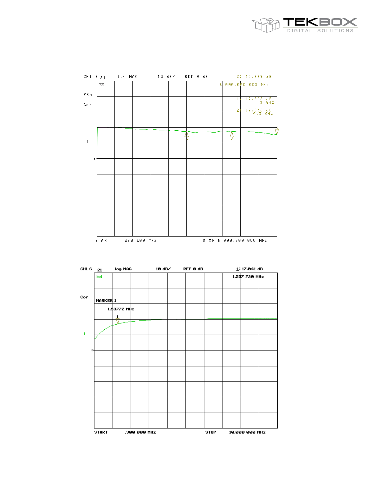
Gain:
Table 1 – TBWA2/20dB gain
Page 9
V1.9
9
H20, H10, H5, E5, TBWA2/20dB, TBWA2/40dB
EMC Near-field Probes + Wideband Amplifier
Picture 13 – TBWA2/20dB, gain, 30 kHz – 6 GHz, lin.
Page 10
V1.9
10
H20, H10, H5, E5, TBWA2/20dB, TBWA2/40dB
EMC Near-field Probes + Wideband Amplifier
Picture 14 – TBWA2/20dB, gain, 300 kHz – 10 MHz, lin.
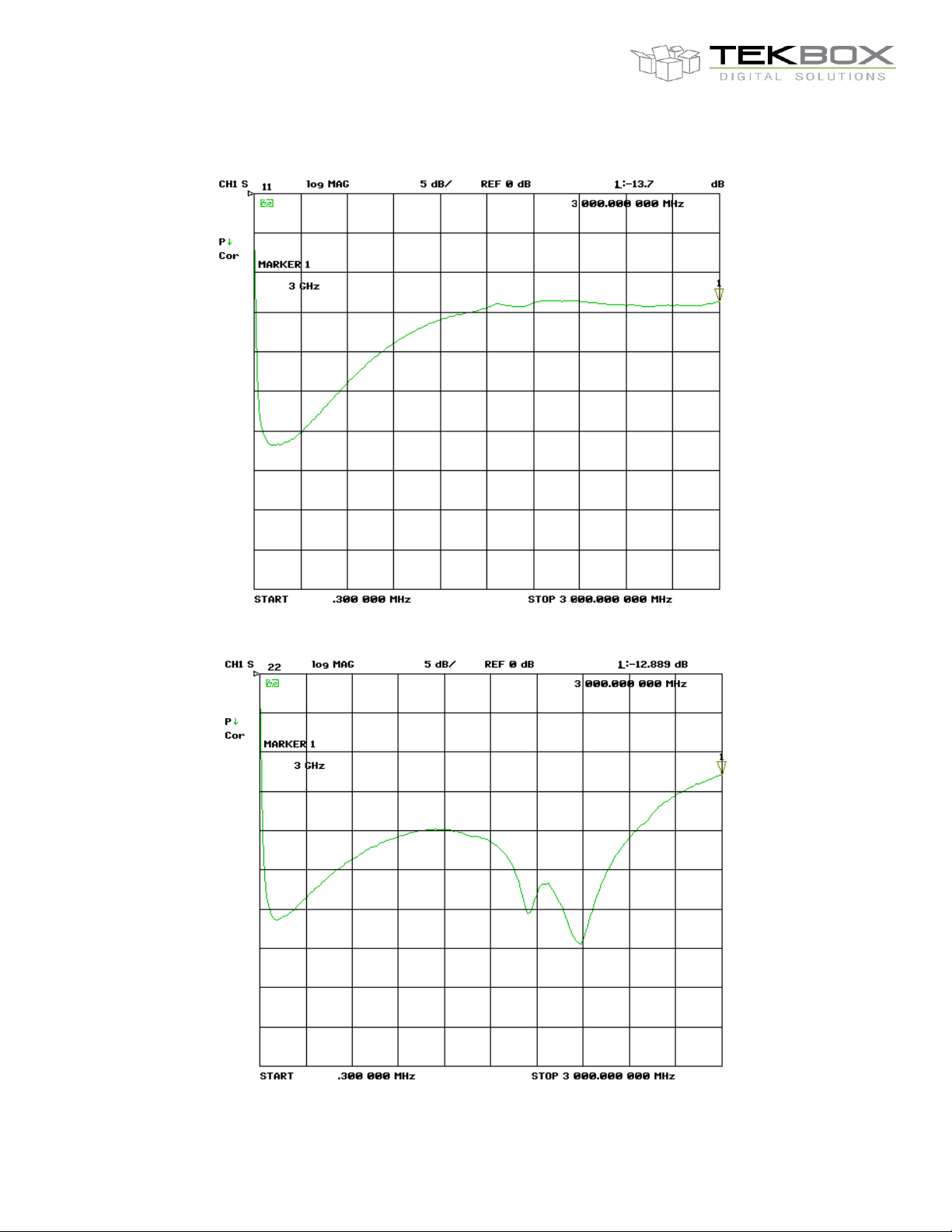
Picture 15 – TBWA2/20dB, input return loss, lS11l, 300 kHz – 3 GHz, lin.
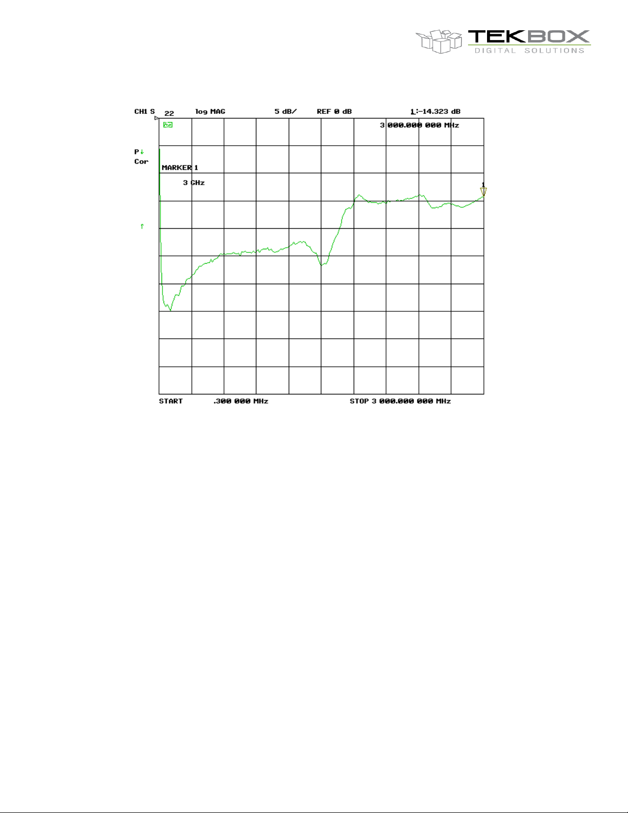
Picture 16 – TBWA2/20dB, output return loss, lS22l, 300 kHz – 3 GHz, lin.
Page 11
V1.9
11
1 MHz
10 MHz
100 MHz
500 MHz
1 GHz
2 GHz
3 GHz
4.5 GHz
6 GHz
30 dB
40.2 dB
40.2 dB
40 dB
39.5 dB
37.6 dB
36.4 dB
34.6 dB
34.7 dB
H20, H10, H5, E5, TBWA2/20dB, TBWA2/40dB
EMC Near-field Probes + Wideband Amplifier
6.2 TBWA2/40dB
Technical Data:
Input: 50 Ohm, SMA
Output: 50 Ohm, SMA
Nominal supply Voltage: 4.5 - 5V, typ. 210mA, Mini-USB-B connector
Maximum supply voltage: 5.5V
Maximum input power: -10dBm
1dB output compression point @ 2GHz: +20dBm
Reverse isolation S12, 0.1 …6GHz: 40dB
Noise Figure @ 2GHz: 5 dB
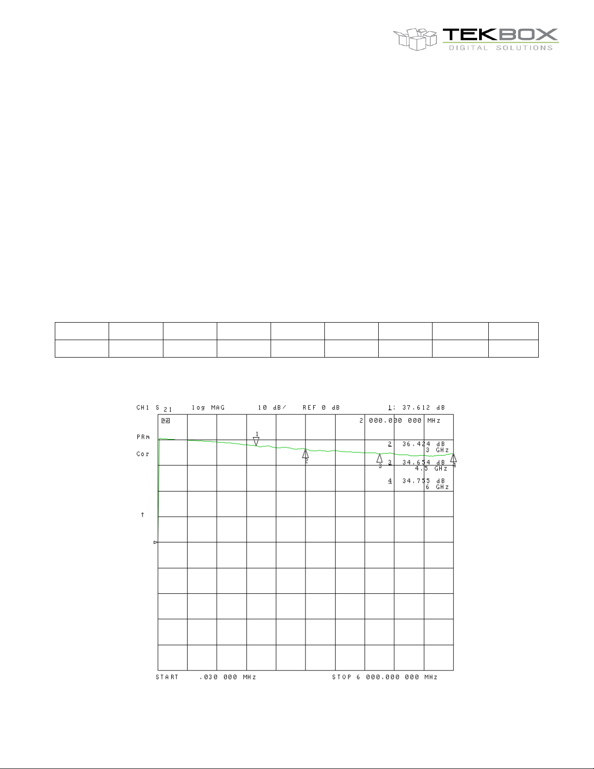
Gain:
Table 2 – TBWA2/40dB gain
Page 12
V1.9
12
H20, H10, H5, E5, TBWA2/20dB, TBWA2/40dB
EMC Near-field Probes + Wideband Amplifier
Picture 17 – TBWA2/40dB, gain, 30 kHz – 6 GHz, lin.
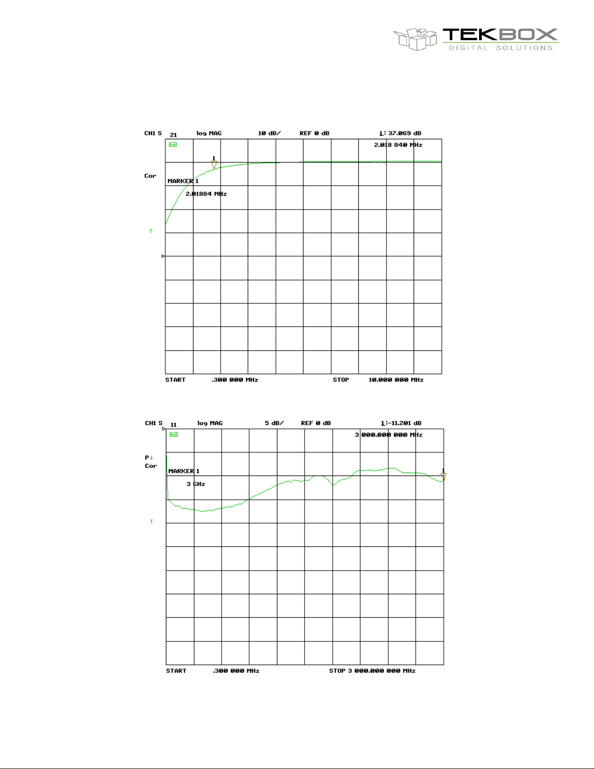
Picture 18 – TBWA2/40dB, gain, 300 kHz – 10 MHz, lin.
Picture 19 – TBWA2/40dB, input return loss, lS11l, 300 kHz – 3 GHz, lin.
Page 13
V1.9
13
H20, H10, H5, E5, TBWA2/20dB, TBWA2/40dB
EMC Near-field Probes + Wideband Amplifier
Picture 20 – TBWA2/40dB, output return loss, lS22l, 300 kHz – 3 GHz, lin.
7 Application
Radiated EMC measurement
RF immunity testing
Contactless (load free) relative measurement of RF signal chains
Contactless (load free) relative measurement of oscillators, modulators, etc.
8 Spectrum analyzer settings
If the probes are used without wideband preamplifier, set the input attenuation to 0dB and turn on the internal
preamplifier, if available on your spectrum analyzer. Furthermore you can increase the dynamic range and
sensitivity by reducing frequency span, resolution bandwidth and video bandwidth.
Page 14
V1.9
14
H20, H10, H5, E5, TBWA2/20dB, TBWA2/40dB
EMC Near-field Probes + Wideband Amplifier
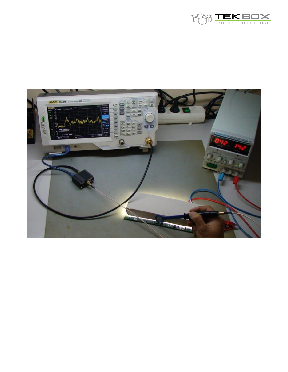
9 Connection of the wideband amplifier
Use the SMB to SMA cable to connect the EMC probe to the input of the wideband amplifier.
Use the SMA to N cable to connect the output of the wideband amplifier with the input of the spectrum analyzer.
Use the USB cable to supply the wideband amplifier from the USB interface of the spectrum analyzer.
Picture 21 – measurement setup; probing the DC/DC converter of a LED lighting PCBA
10 Warning
Do not use the EMC probes to measure devices containing DC
voltages higher than 75V or AC voltages higher than 50V
eff
.
Though the probes are insulated with solder mask, conformal
coating and rubber coating, sharp metal edges may damage the
insulation and cause lethal electrical shocks.
Page 15
V1.9
15
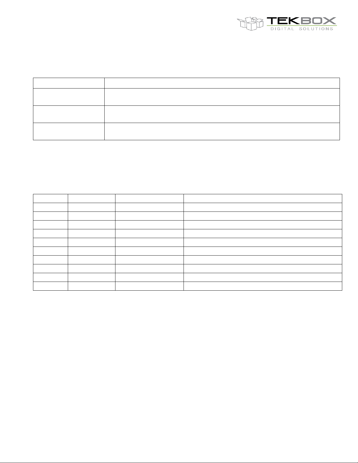
Part Number
Description
TBPS01
EMC probe set consisting of H20, H10, H5, E5, 75cm SMB to SMA cable, measurement
plots, SMA-female to N-male coaxial adapter, transparent plastic box
TBPS01-TBWA2/20dB
EMC probe set consisting of H20, H10, H5, E5, TBSPA2/20dB wideband amplifier, 75cm
SMB to SMA cable, 75cm SMA to N cable, USB cable, wooden case, measurement plots
TBPS01-TBWA2/40dB
EMC probe set consisting of H20, H10, H5, E5, TBSPA/240dB wideband amplifier, 75cm
SMB to SMA cable, 75cm SMA to N cable, USB cable, wooden case, measurement plots
Version
Date
Author
Changes
V1.0
10.3.2014
Mayerhofer
Creation of the document
V1.1
18.7.2014
Mayerhofer
Chapter 6 added
V1.2
28.7.2014
Mayerhofer
Wideband amplifier details added
V1.3
24.10.2014
Mayerhofer
Frequency response updated
V1.4
29.10.2014
Mayerhofer
Chapter 9, picture added
V1.5
19.01.2015
Mayerhofer
TBWA1 amplifiers replaced by TBWA2 (new version)
V1.6
18.12.2015
Mayerhofer
Ordering information updated
V1.7
16.12.2016
Mayerhofer
Picture 1 – text corrected
V1.8
9.1.2017
Mayerhofer
Amplifier frequency response up to 6 GHz
V1.9
17.1.2017
Mayerhofer
Probe coupling loss plots up to 6 GHz
H20, H10, H5, E5, TBWA2/20dB, TBWA2/40dB
EMC Near-field Probes + Wideband Amplifier
11 Ordering Information
Table 3 – Ordering Information
12 History
Table 4 – History
 Loading...