

Tek-Air VorTek VT-5000 series, VorTek VT-7000 series Installation, Operation & Maintenance Manual
Page 1

Vortek
AIRFLOW TRANSMITTER
SERIES VT- 5000 & VT-7000
INSTALLATION, OPERATION
& MAINTENANCE MANUAL
RELEASE 2.1
APRIL 2005
PROTECTED BY US PATENT 4,770,035
TEK-AIR SYSTEMS
41 EAGLE ROAD
DANBURY, CT 06810
TEL. (203) 791- 1400
FAX (203) 798-6534
WWW.TEK-AIR.COM
Page 2

FOREWORD
This manual is designed to provide the user with the information required to install, wire, configure, calibrate,
operate, maintain, and trouble shoot VorTek Air Flow Transmitters. It is important that this manual be read in its entirety
prior to installation and commissioning of VorTek.
While we would like to think that this manual is complete in content and clear in instruction, there may
be questions that we haven’t anticipated. If you have questions that you would prefer to direct to a live
person, we encourage your calls. Technical assistance is available from the service department, at 203-7911400 from 8:30 AM to 5:00 PM ET.
Tek-Air also offers a variety of service and maintenance packages to keep the equipment at peak
performance. For further details contact the Service Department at the above phone number.
WARRANTY
Tek-Air Systems Inc. warrants that the products it manufactures, under normal use and service as described in the Operation and Instruction manual, is free from defects in workmanship and material for a
period of thirty-six months from the date of shipment to the customer. This limited warranty is subject to
the following conditions:
With respect to any repair services rendered, Tek-Air warrants that the parts repaired or replaced will be
in good working condition, under normal use, for the period of the original warranty, or for 90 days from
date of shipment to the customer if the original warranty period has expired.
This warranty is based on the return of the product to Tek-Air’s factory and does not include field repairs.
Periodic maintenance required, as outlined in the Operation and Instruction manual, is the responsibility
of the user.
Unless specifically authorized by Tek-Air in writing, no warranty is made with respect to, and no liability is
assumed in connection with, any goods which are incorporated into other products or equipment by the
Buyer.
The foregoing is in lieu of all other warranties and is subject to the conditions and limitations stated
herein. No other expressed or implied warranty of fitness for particular purpose or merchantability is
made.
The exclusive remedy of the user or purchaser, and the limit of the liability of Tek-Air or any other seller for
any and all losses, injuries, or damage resulting from the use of this product shall be the return of the
product and the refund of the purchase price, or, at the option of Tek-Air or any other seller, the repair or
replacement of the product. In no event shall Tek-Air or any other seller be liable for any incidental or
consequential damages.
Products manufactured by other manufacturers but supplied by Tek-Air carry the original manufacturers
warranty.
Doc.# VT5 OM 050499, Rel. 2.1
Page 3

TABLE OF CONTENTS
1.0 OPERATION
1.1 General Description.................................................................4
1.2 Specifications .......................................................................... 5
1.3 Operation of VorTek
tm
Sensors ................................................6
1.4 Transmitter Operation.............................................................. 7
1.5 Options ....................................................................................8
2.0 INST ALLATION
2.1 Probe Bar Mounting and Location...........................................8
2.1.1 Duct-Mounted Probes............................................................................. 8
2.1.2 Fan Inlet- Mounted Probes .....................................................................9
2.2 Transmitter Mounting and Location.......................................10
2.3 Probe Bar and Transmitter Connection................................. 11
2.4 Transmitter Wiring ................................................................. 11
3.0 STARTUP ADJUSTMENTS
3.1 General Description...............................................................12
3.2 Normal Operation..................................................................13
3.3 Damping Adjustment .............................................................13
3.4 Zero Check............................................................................13
3.5 Quick Calibration Check........................................................14
3.6 Threshold Adjustment............................................................14
4.0 CALIBRATION & MAINTENANCE
4.1 Field Calibration ....................................................................14
4.2 Bench Calibration..................................................................15
4.3 Offset Adjustment..................................................................16
4.4 Calibration Check..................................................................16
4.5 Wave Form Check with an Oscilloscope...............................16
4.6 Troubleshooting.....................................................................17
APPENDICES
Appendix A - VorTek Minimum Installation Requirements........... A1
VorTek Duct Probe Installation Diagrams..........A1-A4
VorTek Fan Inlet Probe Installation Diagrams .A5-A10
Appendix B - Cleaning of VorTek Airflow Measuring Probes....... B1
3VORTEK Doc.# VT5 OM 050499, Rel. 2.1
Page 4

Chapter 1 Operation
1.0 OPERATION
1.1 General Description
The Tek-Air VorTek
insertion probes and an electronic transmitter. The VorTek measurement system
is capable of measuring airflow volume in ducts of all sizes and shapes, as well
as fan inlet bells.
VorTek insertion probes have multiple velocity sensors located along their length.
Each sensor measures airflow velocity using a unique, patented (4,770,035)
application of the digital velocity sensing technique using the principles of vortex
shedding.
Vortex shedding is the generation of eddy currents created by an obstruction in
an air stream. Airflow through each VorTek sensor creates a succession of eddy
currents which are then sensed as pressure pulses. The frequency at which
these pulses are generated, is directly proportional to the velocity of airflow
around the sensor.
tm
airflow measurement system consists of one or more duct
In large ducts, the profile of the air velocity across a duct is often uneven due to
the bends and transitions in the ductwork. In-line devices such as dampers,
elbows, and transitions also create disturbances in the flow profile. To compensate for these varying velocity profiles, multiple VorTek sensors are utilized within
a duct. The frequency outputs of individual sensors are averaged to obtain the
average duct velocity.
The VorTek transmitter totalizes the frequency signals from the individual sensors
to perform true velocity averaging. From this average, an electronic signal (420mA) is generated for direct input to a customer’s control system.
The VorTek transmitter provides several beneficial features to the user, including
adjustable damping, on-line zero check, on-line calibration, sensor diagnostics,
and optional digital indication. This manual will cover the operation, installation,
startup, and calibration of the VorTek probes and transmitter.
4VORTEK Doc.# VT5 OM 050499, Rel. 2.1
Page 5

Chapter 1 Operation
1.2 Specifications
Sensors and Probes
Sensor Type: Vortex shedding
Velocity Range: 350 to 9500 FPM
Probe bar Length: 8" to 72"
Probe bar Configuration: Rectangular, Round, Oval, Fan Inlet
Materials of Construction; Standard:
Mounting Plate: Galvanized steel
Probe bar: Extruded aluminum
Sensor Assembly: Aluminum and ABS
Miscellaneous: EPDM finishing strip
Materials of Construction; Fume hood:
Mounting Plate: Stainless steel
Probe bar: CPVC
Sensor Assembly: CPVC and ABS
Materials of Construction; Stainless steel: (High Temp.)
Mounting Plate: Stainless steel
Probe bar: Stainless steel
Sensor Assembly: Stainless steel
Probe bar Support: Mounting Flange Plate and Threaded Rod w/nuts
Sensors Per Probe: 1 to 6 per Bar
Number of Probe bars per Transmitter: 1 to 4 (16 sensors maximum)
Operational Temperature: -20 to 200°F, (160°F for CPVC)
320°F maximum for high temperature
Weight: Function of probe configuration
Transmitter Electronics
Input: One to Sixteen sensors
Output: 4-20mA, fully isolated; 1-5VDC ; 2-10 VDC
Load Capability: 650 ohms
Voltage: 20-28VAC, 60 Hz
Power: 8 VA, .33 amps at 24 VAC
Probe bar Connections: Plug-in cable, Plenum Rated,10 ft. provided
(longer available as a special option)
Calibration: Adjustable from 0 to 7000 for ducts; 0 to 9000 for inlets
Operational Temperature: 0 to 140°F
Frequency Conversion Error: less than ±0.25% FS (8 sensors)
Temperature Error: less than ±0.5% over 25 to 125°F
Signal Damping: 2 or 4 seconds, selectable
Setup & Diagnostic Controls: Zero check, sensor check, Internal Cali
bration Standard: 122 Hz
Dimensions: 7.5" x 7.5" x 3.5" (WxHxD)
Weight: 5 lbs
Mounting: Surface mount for wall, duct, or panel
5VORTEK Doc.# VT5 OM 050499, Rel. 2.1
Page 6
Chapter 1 Operation
1.3 Operation of VorTek
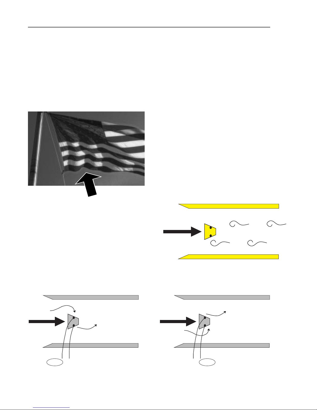
The VorTek Sensing system measures air velocity by a physical principle called
vortex shedding. The vortex shedding phenomena can be witnessed all around
us in everyday life. Swirling vortices, or eddy currents, are generated whenever
air or liquids flow around an obstruction in their flow path. Common examples are
the eddy currents which develop behind rocks in a stream, and in the fluttering of
a flag behind a flag pole. The flag and the flag pole provide the most visual example of how vortex shedding works.
tm
Sensors
The flag pole presents an obstruction in
the path of the airflow, which is the wind.
As the wind passes around the flag
pole, vortices (eddies) are created in the
wake of the pole. These vortices, in
accordance with the laws of nature, are
developed and shed in an alternating
manner, from one side of the flag pole to
the other. The evidence of the shedding
of vortices is in the waving of the flag
itself.
Tek-Air’s unique VorTek flow sensors
use a trapezoidal shaped obstruction
placed in a small tube section to generate stable vortices over a wide range of
low velocities. Pressure sensors sense
the passing of individual eddies. Multiple
VorTek sensors are mounted on probe
supports to provide ample coverage of
the duct cross section.
AIR FLOW
High Pressure
Low Pressure
Low Pressure
AIR FLOW
High Pressure
Pulse
No Pul se
No Pul se
Pulse
6VORTEK Doc.# VT5 OM 050499, Rel. 2.1
Page 7

Chapter 1 Operation
1.4 Transmitter Operation
The enclosure located on the external end of each duct probe bar is the probe
electronics housing. It contains the electronics which sense the vortices generated by the VorTek probes. At the bottom of the enclosure is the electronic connector required to connect each duct probe to the transmitter. A ten foot long
connecting cable is provided for each duct probe for this purpose.
The VorTek transmitter is capable of accepting inputs from as many as four probe
bars from one measuring station, each with a maximum of four VorTek sensors
each. Up to six sensors may be located on a single probe support bar but the
total number of sensors can not exceed 16.
In the simplest sense, the transmitter electronics can be considered a pulse
frequency-to-analog converter. The transmitter receives electronic pulses from
each of the VorTek sensors. As every pulse represents the same increment of
velocity, the pulses need only be summed together and integrated over time to
determine velocity. Additional circuitry converts the total pulses per second into
analog, 4-20mA signal which is proportional to either CFM or FPM.
The VorTek transmitter consists of a minimum of two circuit boards: the Amplifier
board and the mother board. The amplifier board performs the required signal
conditioning on up to eight VorTek sensor inputs. Either one or two amplifier
boards are provided depending on the number of probe bars used at the station.
The mother board accepts the conditioned pulses from the amplifier board(s),
sums them, integrates them, and converts them into a 4-20mA output signal. The
mother board also provides the power supply, calibration adjustments, internal
calibration standard, and circuitry to drive the optional digital display.
A “PROGRAM MODULE” is installed on the mother board and programs the unit
for the correct number of sensors required for the specific configuration. This
module “plugs-in” and can be changed easily for an alternate configuration if
required.
Because airflow is inherently turbulent, it tends to produce fluctuating electronic
output signals if not damped when high turbulence is present. Also, some commercial direct digital temperature control systems update control outputs only on
changing input signals. The rapid input changes caused by airflow turbulence
can cause these types of systems to effectively overload and crash. To allow the
user to select the damping to meet his application, the transmitter includes a
switch-selectable damping constant of either 2 or 4 seconds.
7VORTEK Doc.# VT5 OM 050499, Rel. 2.1
Page 8

Chapter 2 Installation
1.5 Options
Many users prefer to have a digital display as a part of the transmitter. This type
of display is available as an option with the VorTek transmitter. A 3-1/2 digit display is available allowing a display of 0 to 1999 in either CFM or FPM, which is
specified by the customer at the time of purchase. Multipliers of either x10 or
x100 can be used to display up to 200,000 CFM.
2.0 INSTALLATION
The VorTek measurement system consists of two basic elements: the probes and
the transmitter. The VorTek probe bars are inserted into the duct and measure
the velocity of the air moving through the duct. The VorTek transmitter, which is
mounted in close proximity to the probes, converts the electronic pulses generated by the probes into an electronic signal compatible with most DDC control
systems.
The following details are provided on the mounting and installation of the VorTek
transmitter and flow probes. Please read this data carefully and install the equipment in strict accordance with the instructions provided. Should you have any
questions, contact Tek-Air directly.
2.1 Probe Mounting and Location
2.1.1 Duct- Mounted Probes
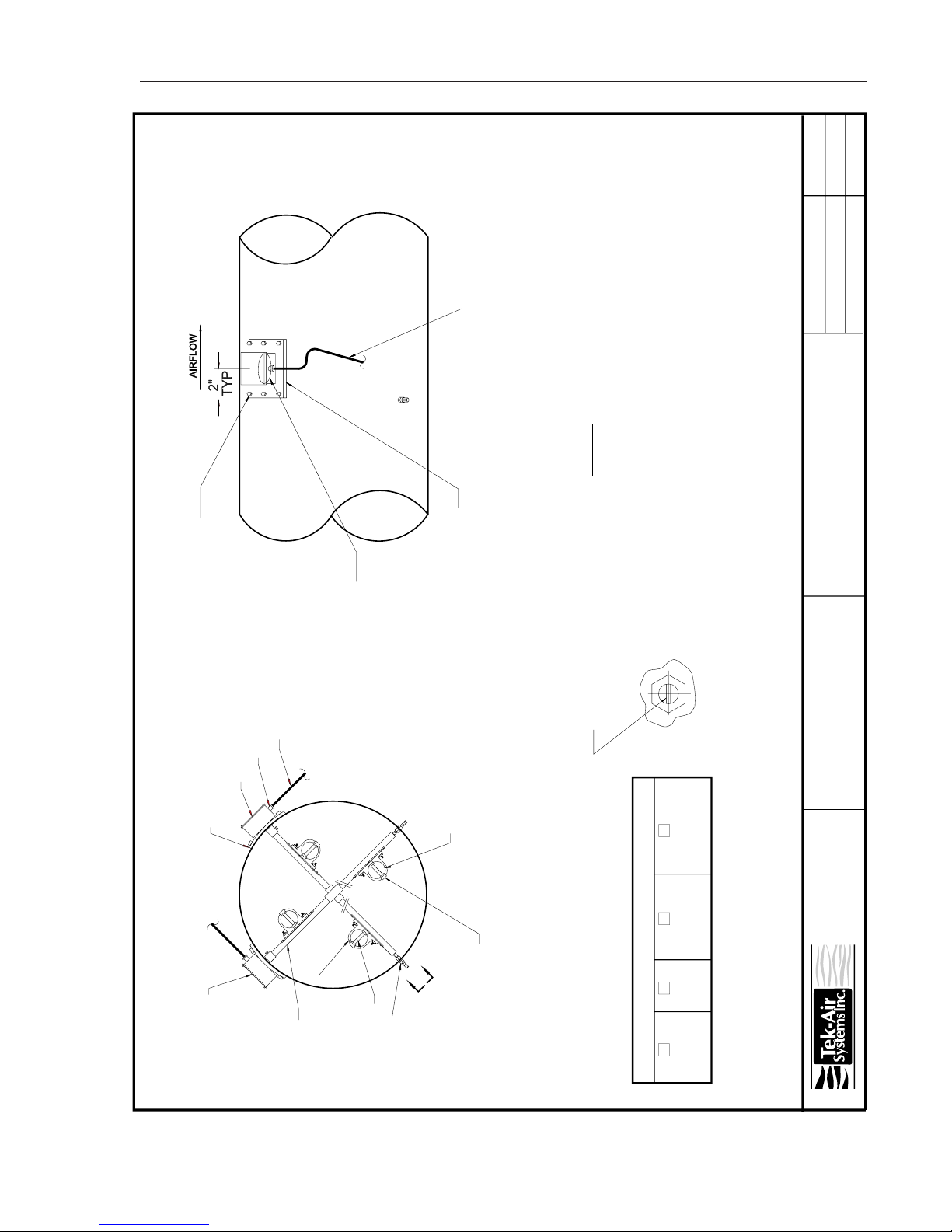
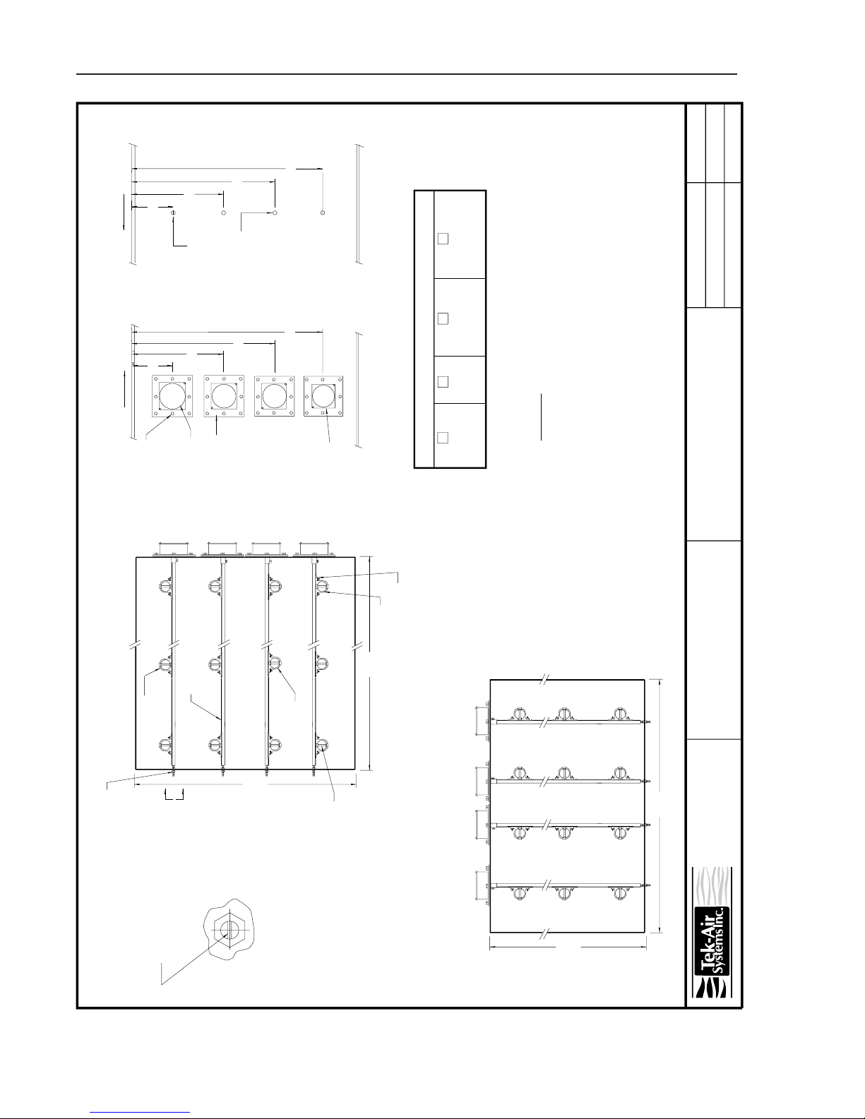
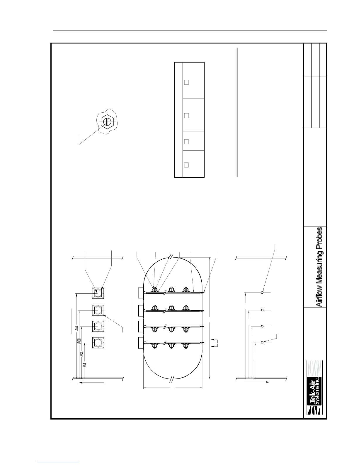
(refer to drawings on pages A-2 thru A-4 of Appendix A)
General- VorTek probe bars are designed for installation in ducts, regardless of
the duct size. Usually, the larger the duct, the more sensing points are required to
provide an accurate measurement of airflow volume. In a typical application,
multiple probe support bars are directly inserted in the duct. Each probe bar has
multiple VorTek sensors for measurement of the air velocity in the area of the
duct it serves.
T urbulent Airflow- Probe design allows for installation in ductwork without the
requirement for special air straighteners. However, care should be taken to avoid
installation within close proximity to:
• Balancing dampers
• Modulating opposed blade dampers
• Non-airfoil type, parallel-blade dampers
• Elbows
• Transitions
• Humidifiers
• Coils
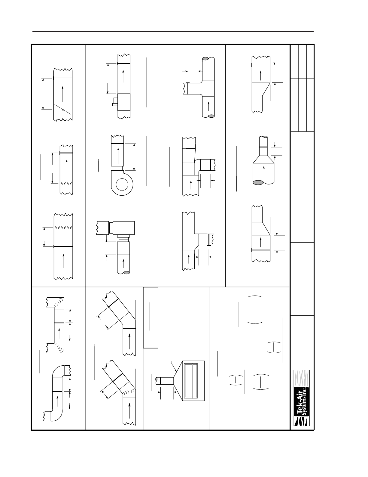
Refer to the drawing “Minimum Installation Requirements”, Appendix A, page A-1
for the
space is available, probe bars should be located so that they have two thirds of
the straight duct length upstream of the probe bars. Keep in mind that locations
other than those specified as minimums often have areas with very high turbu-
minimum acceptable installation criteria for specific applications. If more
8VORTEK Doc.# VT5 OM 050499, Rel. 2.1
Page 9

Chapter 2 Installation
lence and reverse flow. Accurate airflow measurement is impossible in these
locations.
Direction of Flow- VorTek airflow probe bars must be mounted so airflow direction corresponds to the direction indicated by the flow arrow on the duct mounting
flange. Failure to mount the units properly will result in an erroneous or no flow
output. Probes can be mounted in any plane, vertical, or horizontal without effecting the measurement quality. Sensors must be mounted straight in the airflow
stream.
Temperature- VorTek probes are designed for use in normal HVAC applications.
Continuous operation with temperatures over 200 degrees with standard materials of construction is not recommended. Fume hood exhaust sensors with CPVC
construction have a limit of 180°. Close proximity to steam humidifiers and coils
is not recommended. Should a steam valve leak when air is not flowing, temperatures in excess of the recommended maximum can occur. Moisture can also
cause incorrect readings.
Airborne Contaminants- Normal dirt and dust associated with air conditioning
applications will not effect sensor performance. The presence of agglomerating
or sticky particles can cause performance problems and should be avoided.
Should this occur, the probe bars can be removed for cleaning (see Appendix C).
Inspection- Carefully unpack and inspect the probes. If probes have been bent
or broken in shipment, advise Tek-Air immediately.
Installation- Probes are mounted across the duct and attach to the duct on both
sides. A 3 3/4" diameter hole should be located on the side of the duct where the
probe will be inserted. A 5/16" diameter hole is required in the duct wall on the
opposite side of the duct for probes longer than 12".
A sensor probe mounting plate is provided with a neoprene gasket and does not
require the application of special sealants. The flange plate should also not be
insulated to allow for easy removal if ever desired. See Diagram, Appenidix A,
Page A-2.
Large ducts need multiple Probe Bars so flow can be averaged. The bars should be
spaced out on the same “plane” of the duct so the sensors are located to pick up
the flow. Refer to the A
, A2, A3,A4 (as required) dimensions on submittal schedule.
1
2.1.2 Fan Inlet- Mounted Probes
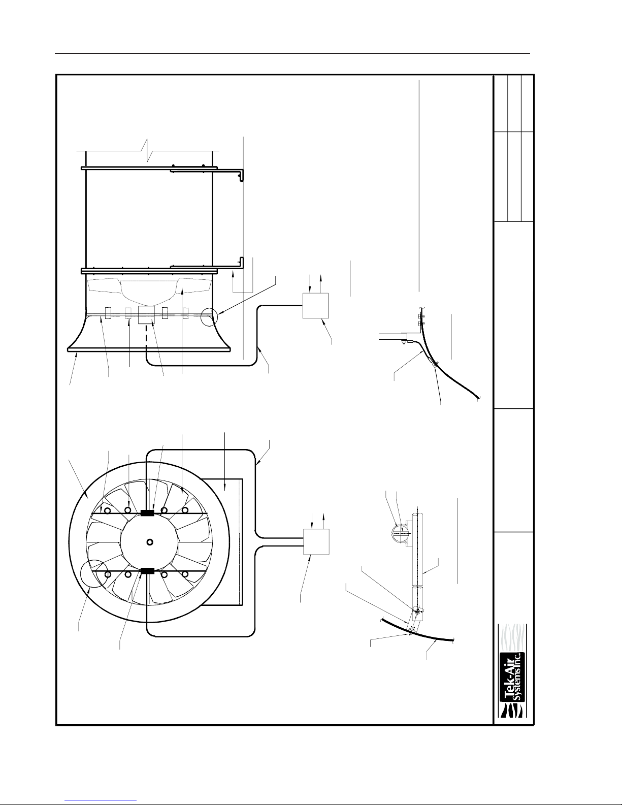
(refer to drawings on pages A-5 thru A-10 in Appendix A)
General- The VT-7000 Series Vortek Fan Inlet Probes are in pairs of bars for
each inlet. For single-inlet fans, one pair is provided. For double-inlet fans, two
pairs are provided. One Transmitter serves all bars in the one or two-pair set. On
bars sized for fan inlet diameters of 24" I.D. or less, the bar electronics are
mounted in an enclosure which mounts separately from the bars and is permanently connected to the bars via flexible non-metallic conduit. On bars sized for
fan inlet diameters greater than 24" I.D., the bar electronics are housed in enclo-
9VORTEK Doc.# VT5 OM 050499, Rel. 2.1
Page 10

Chapter 2 Installation
sures which are mounted in the center of each bar. In both cases the bar electronics connect to the Transmitter via prefab cables, which are factory-connected
to the bar electronics enclosures.
Direction of Flow- The probes must be positioned so that they face into the
airflow: the Safety Cables on the ends of the bars leading
and the mounting brackets facing back into the fan inlet bell. On bars for fan
inlets over 24" I.D., the bar electronics controller has an airflow direction label
affixed to it for your convenience.
Mounting the Probe Bars- Hold the bars in place as shown in the drawing
(choose the drawing that matches the fan type which you are working with).
Make sure the bars are positioned as described above. Mark, on the inlet bell
surface, the mounting hole locations of the brackets on the ends of the bars.
Remove the bars from the inlet and drill pilot holes for #14 self-tapping screws
where you marked them.
out of the fan inlet bell,
Remove the brackets from the ends of the bars (
nuts and Safety Cables). Screw the brackets to the inlet bell surface using thread
locking compound and #14 self-tapping screws.
Re-attach the bars to the installed mounting brackets, being careful to face the
bars in the correct direction, and to re-attach the Safety Cables as they were
before. Tighten the NyLok nuts on the bar mounting bolts sufficiently to prevent
loosening of the nuts through vibration. Note: If a screw, nut, or bolt is stripped,
replace it with the same type fastener. If a drilled pilot hole is stripped, DRILL
ANOTHER HOLE and move the probe according.
DO NOT USE STRIPPED HOLES OR FASTENERS AS DAMAGE TO THE
PROBES AND FAN CAN RESULT FROM PROBES COMING LOOSE AND
BEING DRAWN INTO THE FAN WHEEL!
Stretch the Safety Cables outward from the bars towards the outside of the fan,
leaving no slack in the cable. The eyelet on the end of the cable must be
screwed to a sturdy, metallic surface such as the bell, fan casing, or bearing
support. Mark where you intend to srew the eyelets, and drill #14 self-tapping
screw pilot holes. Using thread locking compound and #14 self-tapping screws,
screw the eyelets down, tighening the screws sufficiently to prevent loosening
due to vibration, but DO NOT STRIP THEM!
be careful not to lose the bolts,
Run the cables out to where the Transmitter will be mounted, leaving sufficient
slack to allow easy plugging and unplugging of the cables into the transmitter
receptacles.
2.2 Transmitter Mounting and Location
General- The transmitter is typically located in close proximity to the duct inser-
tion probe bars and transmits a 4-20mA signal over long distances to the customers control system.
Transmitter Location- The VorTek transmitter is small and designed for mount-
10VORTEK Doc.# VT5 OM 050499, Rel. 2.1
Page 11
Chapter 3 Startup Adjustments
ing either on the duct or on a wall, column, or other support close to the point of
measurement. The transmitter housing is a general purpose enclosure and is
therefore not designed for mounting outdoors or in areas requiring explosionproof classification. For outdoor use, a Nema 4 enclosure can be purchased as
an option. For installation in explosion-proof areas contact factory. Areas where
the temperatures are expected to exceed 125° F for extended periods of time are
to be avoided.
2.3 Probe and Transmitter Connection
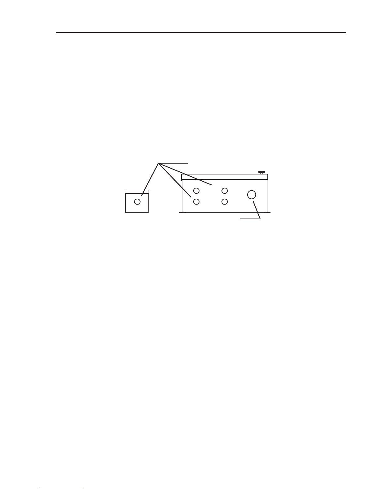
Probe Connection- Ten foot connecting cables are provided for each insertion probe.
This cable has a shielded 8 pin connector from the probe electronics enclosure and is
plugged into either connector on the bottom of the transmitter.
CABLE CONNECTORS
34
12
Probes should be plugged in to the transmitter in numeric sequence (ie. 1, 2, 3, 4). If one
probe is used it should be plugged into connector 1. If three probes are used they should
be plugged into connectors 1, 2, and 3. It is not important however which probe is plugged
in to a particular connector. After connectors have been plugged in it is advisable to anchor them with tie wraps.
2.4 Transmitter Wiring
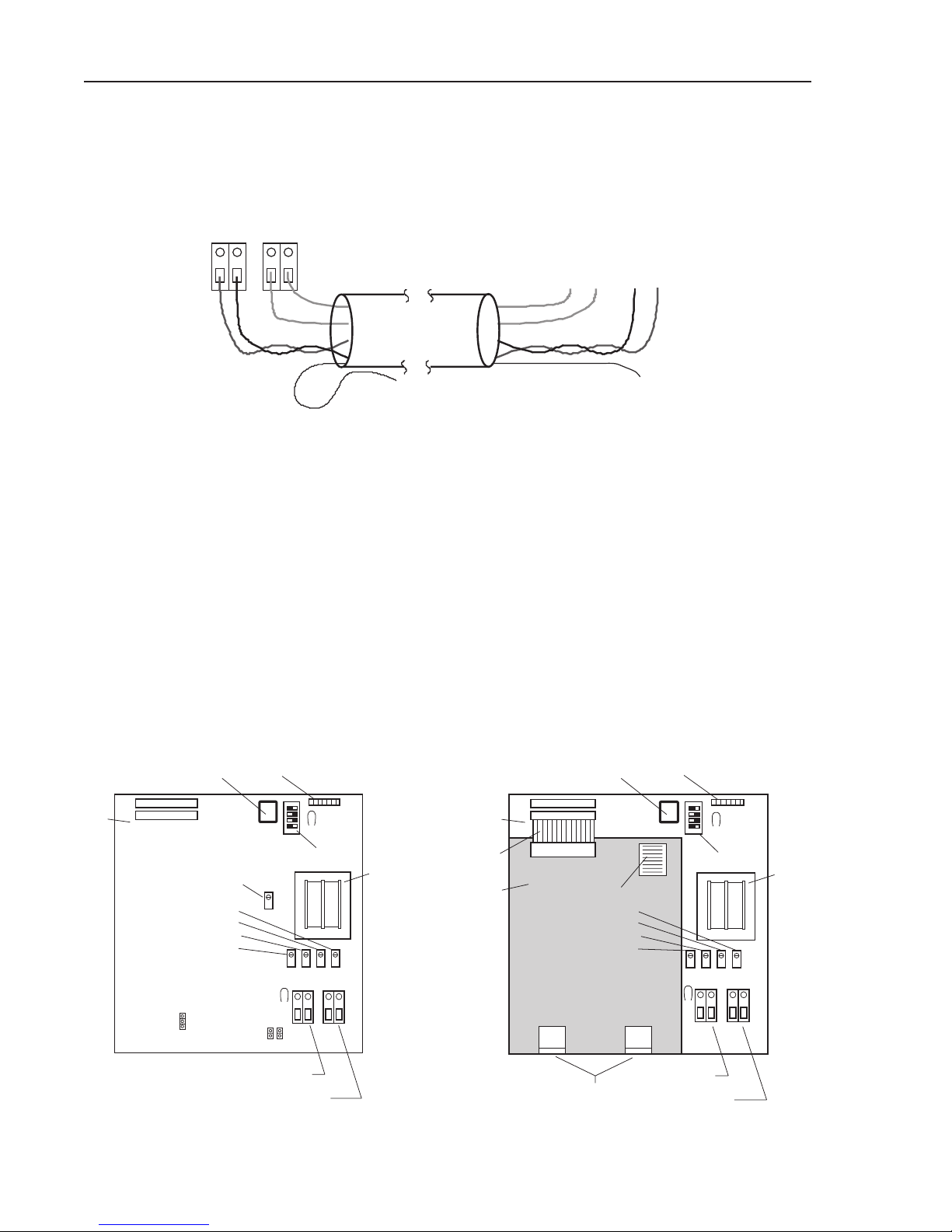
Terminations- Inside the transmitter on the bottom right are two pairs of terminals. The
left most pair are the signal output terminals. (See Fig. 3) The right most are for 24VAC
Power input. Transmitter power is 24 Volts AC, 8VA maximum current. Power may fluctuate ±20% without effect.
Signal and power wiring can be run in a common shielded cable or separately. If run
separately, signal cable should be shielded. In either case, shields should be tied to the
input device (controller) common and taped back on the other end. (See Fig. 2) T ypically,
shields are terminated at the controller.
CONDUIT ENTRY
TRANSMITTER
Probe Cable Connection Points
Figure 1
Output Signal- T ransmitter output is 4-20mA and is capable of driving up to 650 ohms of
load. Control equipment which accepts voltage inputs can be accommodated with internal
jumpers that will generate a 1-5VDC output or a 2-10 VDC output. SEE DRAWING ON
NEXT PAGE.
11VORTEK Doc.# VT5 OM 050499, Rel. 2.1
Page 12
Chapter 3 Startup Adjustments
- +
4-20ma
OUTPUT
24 VAC
POWER
SHIELD
Tie to Controller Common
Transmitter Power and Signal Wiring
3.0 STARTUP ADJUSTMENTS
3.1 General Description
The VorTek airflow transmitter has several modes of operation which are determined by setting the four position DIP (Dual Inline Package) switch located on the
upper right corner of the mother board. This switch is utilized for adjusting the damping, transmitter zero check, and quick calibration check.In addition to this switch,
potentiometers are available for adjusting T ransmitter Zero, Full Scale, Frequency
Tape Back Drain Line
at Transmitter &
Figure 2
24VAC
POWER
CONTROLLER COMMON
INPUT
+ -
Offset, and digital indicator output. See Figure 3 below.
ZERO
SPAN
OFFSET
DISPLAY
DISPLAY
OUTPUT
JP2 JP3
TP1
SIGNAL
POWER
TP5
SETUP
DIP
TRANSFORMER
MOTHER
BOARD
RIBBON
CABLE
AMPLIFI ER
BOARD
PROGRAM
MODULE
JUMPERS
ZERO
SPAN
OFFSET
DISPLAY
PROBE BAR INPUTS
DISPLAY
OUTPUT
TP5
SETUP
DIP
TP1
SIGNAL
POWER
PROGRAM
MODULE
MOTHER
BOARD
THRESHOLD POT.
JP1 (3-pin)
Figure 3 - Vortek Mother Board, (left); VorTek mother board showing Amplifier board installed (right).
TRANSFORMER
12VORTEK Doc.# VT5 OM 050499, Rel. 2.1
Page 13
Chapter 4 Calibration and Maintenance
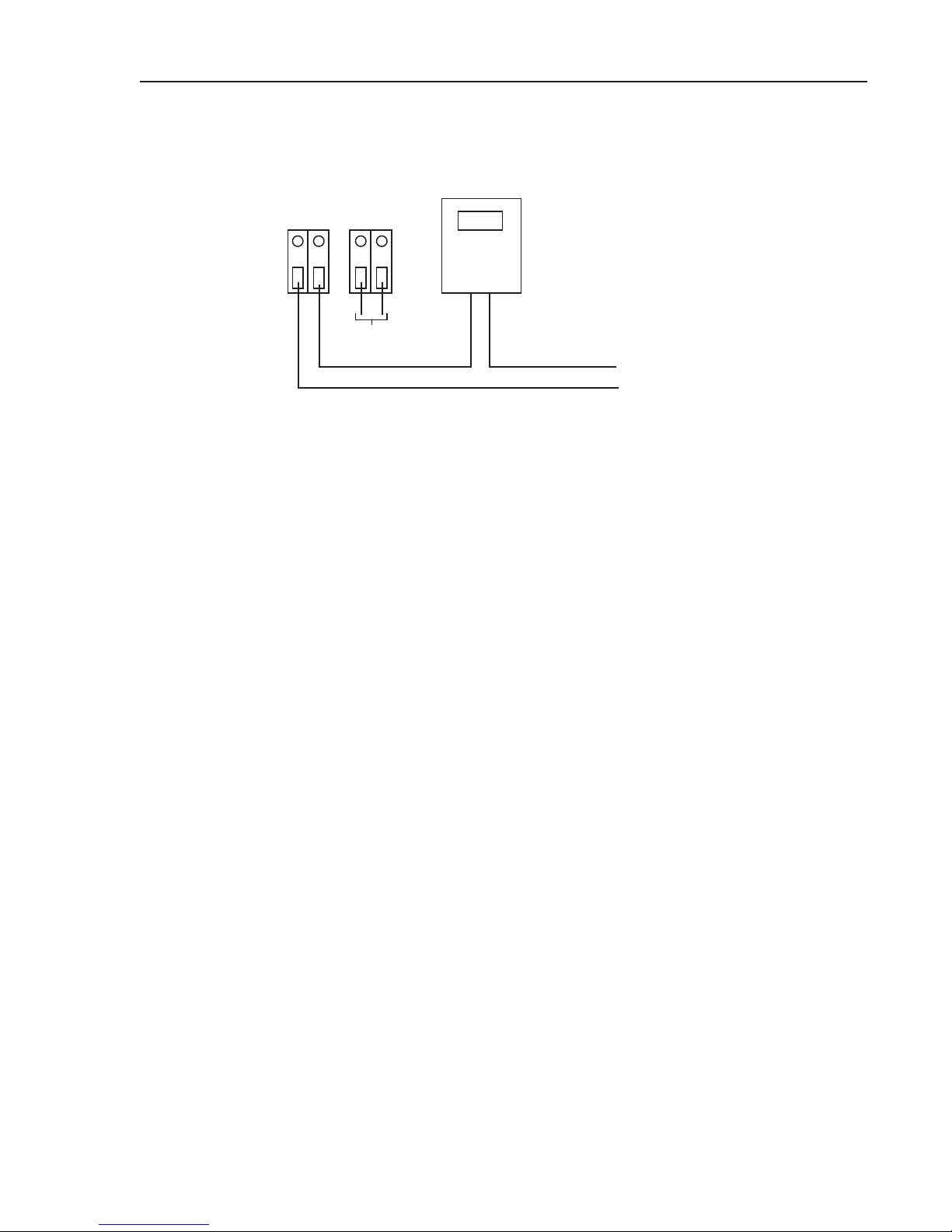
Transmitter output checks can be made by connecting a voltmeter set for DC
milliamps, in series as follows;
DVM
SIGNAL POWER
2.34
- +
24VAC
3.2 Normal Operation
In order for the transmitter to function properly as a flow measurement device the DIP
switch must be set as follows;
DIP 1 On or Off
DIP 2 On
DIP 3 On
DIP 4 Off
3.3 Damping Adjustment
Damping can be set by using DIP switch number 1. With switch one in the “on” position minor
damping is in effect. With switch one in the “off” position the normal damping is doubled.
+ -
Figure 4
+
SIGNA L W IRES
-
3.4 Zero Check
Transmitter zero output (4-20mA) can be simulated by setting DIP switches 2, 3, and 4
as follows, and removing the probe connectors from the bottom of the transmitter;
With the voltmeter set for milliamps and connected in series (See fig. 4) with the 420mA output, the zero-flow output can be adjusted by utilizing the zero calibration
potentiometer. At these settings the meter should read 4mA. Reinstall the probe connectors when complete. Remember to return DIP switches to normal operation or
continue on to Quick Calibration Check.
DIP 1 On or Off
DIP 2 Off
DIP 3 Off
DIP 4 Off
13VORTEK Doc.# VT5 OM 050499, Rel. 2.1
Page 14

Chapter 4 Calibration and Maintenance
3.5 Quick Calibration Check
Transmitter calibration can be checked quickly by setting DIP switches 2, 3, and 4 as
follows, and then removing the probe connectors from the bottom of the transmitter;
DIP 1 On or Off
DIP 2 Off
DIP 3 Off
DIP 4 On
The proper output of the transmitter can be established by making the following calculation. Full scale Hz data can be obtained from the transmitter label on the front door;
Expected mA= [16*(122/Full Scale Frequency Hz)]+4
If the value observed does not agree with the value expected, ±0.5% full scale, then the
transmitter may require recalibration. The use of this internal frequency standard for
calibration of full scale values is possible but will not be as accurate as calibration using
a frequency generator set at full scale Hz.
3.6 Threshold Adjustment
The threshold adjustment is normally made on a calibration bench. However, the threshold can be set empirically in the field by following the procedure in section 4.2. The
threshold adjustment serves to limit the lower operating limit of the transmitter to increase sensitivity at low flow conditions.
Threshold is factory set at a point equivalent to 350 FPM. Below this level the threshold
circuit forces the output to go to 4.0 ma. Lowering the threshold below 350 increases
chances that the transmitter may show flow when none is present if a high ambient
noise condition is present.
The threshold should only be adjusted if the transmitter indicates flow when in fact there
is none present. Before adjusting, check to see that zero is properly adjusted. Then,
with no flow in the duct, turn the threshold adjustment clockwise until the transmitter
indicates 4 ma.
4.0 CALIBRATION & MAINTENANCE
4.1 Field Calibration
The VorTek transmitter comes calibrated for the CFM or FPM specified by the customer.
The calibration factor is established as a function of the type of VorTek sensor utilized in
the construction of the probe bars. These calibration factors are established by test and
represent flow conditions expected when normal Minimum Installation Requirements are
observed. (See Appendix A, page A-1)
When these conditions are not present and duct turbulence is a problem, corrections
may be required to match flow transmitter output to readings observed by traverse. In
these cases transmitter span can be adjusted to read the desired output. Adjustment of
transmitter span will not effect transmitter zero.
14VORTEK Doc.# VT5 OM 050499, Rel. 2.1
Page 15

Chapter 4 Calibration and Maintenance
For best results, a traverse should be done with the airflow at a fixed CFM. This can be
done by: Fixing the output to the damper/valve which throttles the air in that duct, or by
removing the output to the valve/damper, and keeping all doors closed in the area that
is affected by this airflow.
The CFM reading can then be compared to the transmitter output. A milliamp meter
should be connected in series with the output signal wires. (refer to figure 4 on page 11).
The reading will fall between 4 and 20 mA. Use the formula below to convert the mA
value to the equivalent CFM. The transmitter Full Scale CFM can be found on the
transmitter enclosure.
Current Transmitter CFM Value = [Full Scale CFM/16]*(milliamp reading - 4)
If the transmitter CFM reads differently than the traverse, then an adjustment can be
made. If there is a front end system receiving the control signal. A multiplication constant should be added to the scaling formula to agree with a balancer reading. If this is
not possible, the transmitter itself can be adjusted. First calculate the corresponding
milliamp value which matches the traversed CFM with this formula:
New desired mA value = [(traversed CFM/Transmitter Full Scale CFM)* 16]+4
Turn the span potentiometer (see figure 3) clockwise to increase the mA signal, counter
clockwise to decrease the signal, until the desired mA signal is output.
4.2 Bench Calibration
Full transmitter calibration is normally calibrated at a bench, although it is possible to
bring the bench calibration instruments to the transmitter in the field. Connect a digital
voltmeter to the transmitter as shown in figure 4. A frequency generator is required and
can be used in conjunction with a Multi-meter. The full procedure is as follows.
Set Zero- Set switches 2, 3, and 4 to “OFF”. Adjust the “ZERO” potentiometer until 4.00
mA is read on the digital voltmeter.
Set Full Scale- (see figure 5, next page) Set switches 2, 3, and 4 off. Connect the
negative lead of the frequency generator to TP 1 on the mother board (next to the wire
connectors). Connect the positive lead to TP 5. Set the generator to the full scale Hertz
indicated on the label fixed to the transmitter enclosure. Set the frequency generator to
sinusoidal
ometer until the output reads 20.0 mA. Turn the span potentiometer clockwise to increase the mA signal, counter clockwise to decrease the signal.
Set Optional Display- With the above connections and settings in place from the
previous step, adjust the “DVM” potentiometer to read the appropriate scale display
value. As the maximum display is 1999, a multiplier of x10 or x100 may have to be
utilized to get the total CFM display.
Threshold Adjustment- With the above connections and settings in place from the
previous step, set the frequency generator to approximately 60 Hz. Turn the “THRES”
potentiometer clockwise until the transmitter output switches to 4 ma. Then, slowly turn
the “THRES” adjustment counter clockwise until the output switches back to a reading
other than 4 mA. Threshold is now set.
wave and the output voltage to the minimum level. Adjust the span potenti-
Return To Service- Return switches 2 and 3 to the “ON” position prior to returning the
unit to service.
15VORTEK Doc.# VT5 OM 050499, Rel. 2.1
Page 16
Chapter 4 Calibration and Maintenance
4.3 Offset Adjustment
The tag on the transmitter enclosure may have two separate values for frequency; Full
scale Hz and Span Hz. If this is the case, the transmitter was factory calibrated with an
offset. To set the offset, follow the set up procedure in 4.2 first. Next turn the offset
potentiometer (see figure 5) counter clockwise all the way. Now input the span frequency to the transmitter, and adjust the span potentiometer until the output is 20.0 mA.
Next input the Full Scale frequency. The mA output will go up. Turn the offset potentiometer clockwise until the output is 20.0 mA again. The adjustment is complete.
4.4 Calibration Check
1. Follow the setup instructions shown in section 4.2 (in the “Set full scale” section) of
the manual.
2. The check should include 3 points: 1/2 full scale frequency, 3/4 full scale frequency,
and the full scale frequency. Input these frequencies using the method in “Set full
scale”. The transmitter output will be 12 mA, 16 mA, and 20 mA respectively.
3. If the calibration does not match the above, recalibration will be required. The calibration should match the entire range of operation. If it agrees at the maximum frequency but not in the center, there may be a problem with the way the unit is configured.
It is likely that jumper JP 1 is not set properly. It should be in the down position if full
scale frequency is greater than 600 Hz.
4.5 Wave form check with an oscilloscope
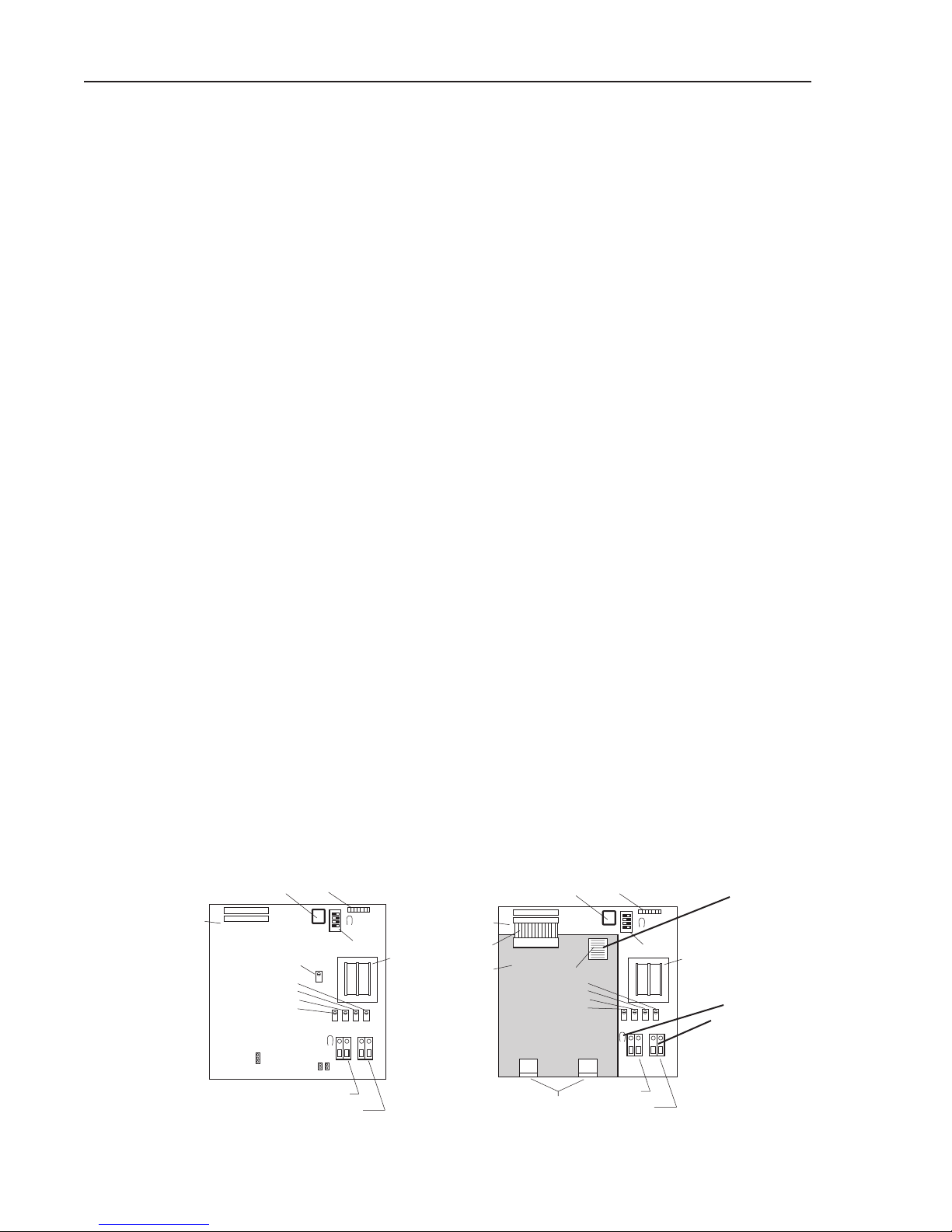
Voltage Input - See figure 5, below. Set up the oscilloscope to read wave forms clearly
on the screen. To check the power input, set the scope to read 24VAC. Touch the
negative test lead to either screw in the power wire connector (A), and the positive lead
to the other screw. The screen should read 60Hz.
Connect the negative lead to the test point 1 (TP1) (B) on the mother board. Connect
the positive lead to one of the exposed metal jumpers (C) on the amplifier board. A
clean, square wave should appear, and the numerical frequency value should not
bounce more the 20% for a good signal. Check each of the thin metal jumpers and read
the values. The average frequencies of the jumpers should be fairly close in value. If
there are two amplifier boards on top of the mother board, the top amplifier board must
be removed.
DISPLAY
PROGRAM
OUTPUT
MODULE
MOTHER
BOARD
THRESHOLD POT.
ZERO
SPAN
OFFSET
DISPLAY
TP5
SETUP
DIP
TRANSFORMER
TP1
MOTHER
BOARD
RIBBON
CABLE
SUMMI NG
BOARD
PROGRAM
MODULE
JUMPERS
DISPLAY
ZERO
SPAN
OFFSET
DISPLAY
OUTPUT
B
TP5
SETUP
DIP
TRANSFORMER
C
TP1
A
JP1 (3-pin)
JP2 JP3
Figure 5 - Vortek Mother Board, (left); VorTek mother board showing summing board (right).
SIGNAL
POWER
PROBE INPUTS
SIGNAL
POWER
16VORTEK Doc.# VT5 OM 050499, Rel. 2.1
Page 17
Chapter 4 Calibration and Maintenance
Output Signal
always at 4mA
Flow Above
350 FPM with
Linear Profile?
DIPs
Set to Operate?
Probe Cables
Plugged in?
Establish
Flow in Duct
Set as Follows:
1-Either ON or OFF
2-ON
3-OFF
4-OFF
Plug in
Cables
Contact Tek-Air Systems
for Assistance
Yes
Yes
Yes
No
No
No
Probes in
Backwards?
No
Yes
Reinstall in
Proper Direction
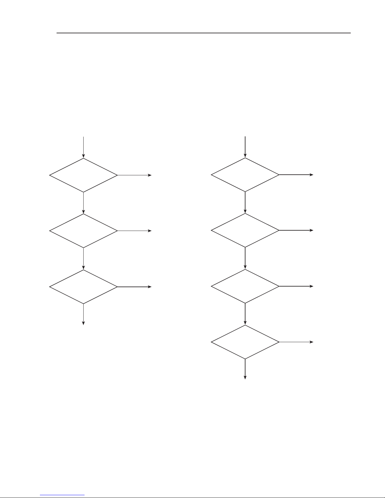
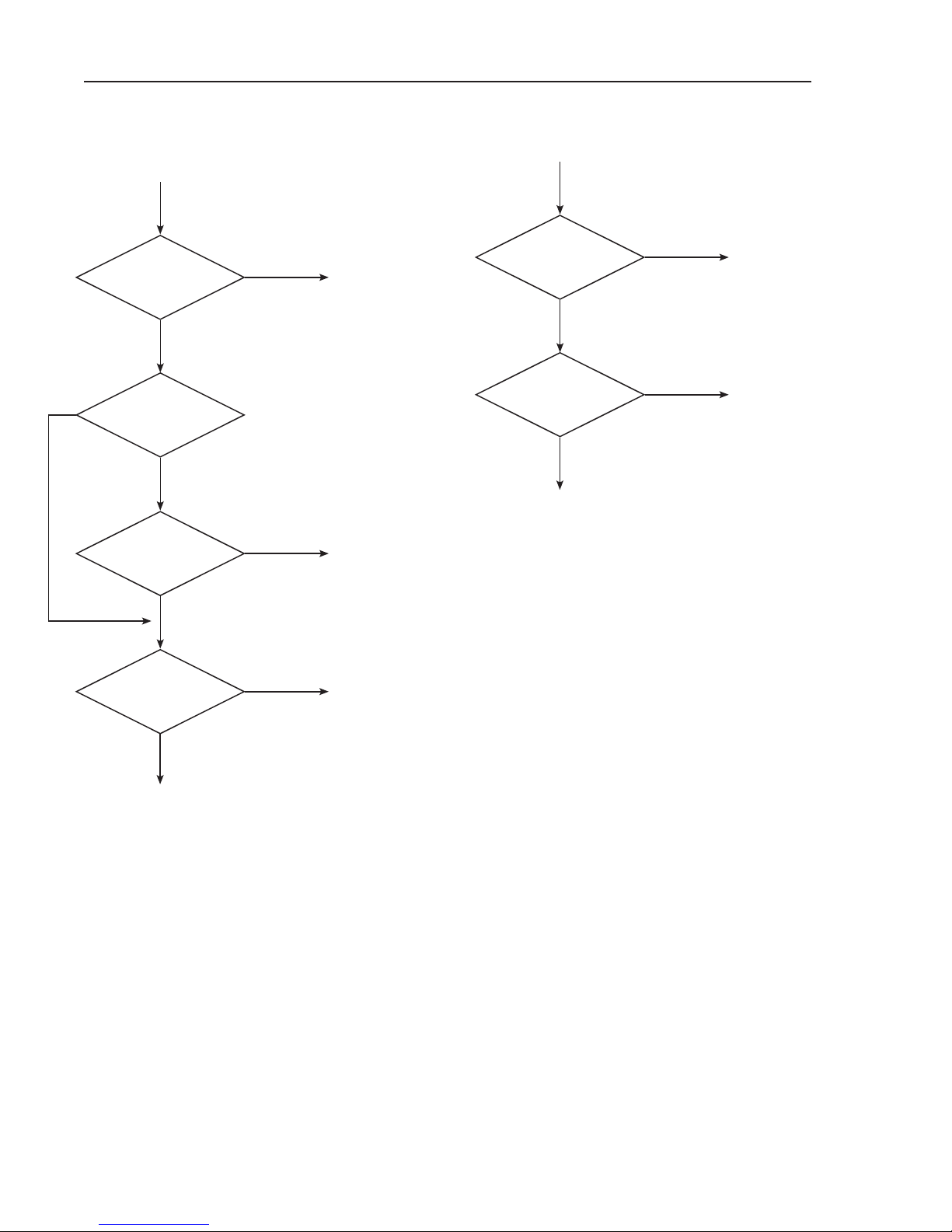
4.6 Trouble Shooting
The following flow charts are designed to aid in trouble shooting the transmitter
and flow sensors should problems be experienced in commissioning the airflow
measurement system.
No Signal
Output
a. Open Circuit
b. Loop resistance above 650 Ohms
c. Short to ground i n “+” wire
24VAC
Present
Yes
Output
Polarity Correct?
Yes
No_ Output
w/signal lines connected
Output w/signal lines
Disconnected
Yes
Correct possible signal
transmission line problems
No
No
No
Correct
Power
(Maintain Polarity)
Correct
Polari ty
Contact
Tek-Air Systems
for Assistance
17VORTEK Doc.# VT5 OM 050499, Rel. 2.1
Page 18
Chapter 4 Calibration and Maintenance
Yes
High or Constant
Output, Output
w/No_ Flow Present
in duct (verified)
DIPs
Set to Operate?
Yes
Unplug Cables,
4mA?
No
Check Zero
(Section 3.4)
4mA?
No
No
Set as Follows:
1-ON or OFF
2-ON
3-ON
4-OFF
Contact
Tek-Air Systems
for Assistance
Large Difference between
actual Measured CFM &
Vortek indicated CFM
DIPs
Set to Operate?
Yes
Probes in
Proper Locati on?
Yes
Unit may be out of calibration.
See section 4.1, Field Calibration
No
No
Set as Follows:
1-Either ON or OFF
2-ON
3-ON
4-OFF
Relocate probes; refer to
Appendix 1, Page A-1
Yes
Probes
mounted in duct
Backwards?
Yes
Plug-in Cables
Place Unit in
Operation
No
Reinstall in
Proper Directi on
18VORTEK Doc.# VT5 OM 050499, Rel. 2.1
Page 19

19VORTEK Doc.# VT5 OM 050499, Rel. 2.1
Page 20
Appendices Appendix A
2X
5X
4X
3X
General Notes
X = Average Duct Dimension
Dampers
Duct Transitions
Fans
Angle Fittings
Centrifugal Inlet
Centrifugal Discharge
Vane-Axial Discharge
Elbows
Sweep
2X
90° Vaned
2X
X
X
Duct Take-Offs
Hoods
Formulas
>15°
<15°
(12" Min)
Not
Recommended
5X
2X
6X
2X
2X
2X
30°
X
30°
2X
2X
3X
Bell Transition
D = Diameter
H = Height in InchesW = Width in Inches
Rect. Duct Area =
W x H
144
Circ. Duct Area =
π
x
144
D
2
2
Design CFM
Duct Area
Design Velocity =
Duct Velocity
3020
2
Oval Duct Area =
2
H
+ ((W - H) x H)
2
144
π
x
Probe Velocity
Pressure =
Engineering Department
43 Beaver Brook Road
Danbury, CT 06810
(203) 791-1400 Phone
(203) 798-6534 Fax
VorTek
Airflow Measuring Probes
Minimum Installation Requirements
& Formulas
Revision Letter: A
Dwg. No:
Revision Date: 4/21/97
Filename: VT-MIN.CDR
Drawn By: GV
20VORTEK Doc.# VT5 OM 050499, Rel. 2.1
A-1
Page 21
Appendices Appendix A
Engineering Department
43 Beaver Brook Road
Danbury, CT 06810
(203) 791-1400 Phone
(203) 798-6534 Fax
VorTek
Installation Drawing
Revision Letter: A
Index No: 1-1
Revision Date: 12/11/96
Filename: T-VT5100A.CDR
Drawn By: GV
SENSOR ENCLOSURE AND
NOTES:
1. INSTALL IN ACCORDANCE WITH AIRFLOW DIRECTION
INDICATOR.
2. FOR QTY. OF PROBES & SENSORS PER PROBE
SEE SCHEDULE.
3. FOR SINGLE BAR UNITS USE PROBE ASS'Y 1 ONLY.
FOR UNITS WITH TWO BARS USE PROBE ASS'Y 1 & 2.
4. FOR DUCT DIAMETERS OF 14" OR LESS PROBE IS
CAPPED WITH NO STUDS OR NUTS PROVIDED.
IN THIS CASE, NO (5/16") HOLE SHOULD BE DRILLED.
SLOT IN ROD TO BE
ALIGNED WITH AIRFLOW
DIRECTION
SECTION A-A
PROBE ALIGNMENT SLOT
REQ'D FOR ALL BARS
DUCT CROSS SECTION
MOUNTING PLATE
PROBE BAR
PREFAB CABLE
SENSOR CLAMP
SHEDDER BAR
SHROUD
TO TRANSMITTER
TYPICAL SENSOR
(FOR QTY. OF SENSORS
PER PROBE SEE SCHEDULE).
PROBE ASS'Y 1
STRAIN RELIEF FITTING
PROBE ASS'Y 2
(IF APPLICABLE)
5/16" STUD
W/LOCK NUTS
(SEE NOTE 4)
A
A
DUCTWORK FOR
INSERTION OF PROBE
MOUNTING PLATE
CONNECTION CABLE
INSERTION SIDE
#10 TEK
SCREW (TYP.)
(INCLUDES INTEGRAL GASKET)
3 3/4" DIA. HOLE IN
6" X 6"
Airflow Measuring Probes
Circular Duct Insertion Probes
Selection of Materials For Construction
Aluminum
& ABS
CPVC
& ABS
304 St Steel High Temp.
St. Steel
21VORTEK Doc.# VT5 OM 050499, Rel. 2.1
A-2
Page 22
Appendices Appendix A
Engineering Department
43 Beaver Brook Road
Danbury, CT 06810
(203) 791-1400 Phone
(203) 798-6534 Fax
VorTek
Revision Letter: A
Index No: 1-2
Revision Date: 12/6/96
Filename: T-VT5200B.CDR
Drawn By: GV
Airflow Measuring Probes
Installation Drawing
Rectangular Duct Insertion Probes
CROSS SECTION
MOUNTING ACROSS WIDTH
#10 TEK
SCREW
MOUNTING
INSERTION SIDE
AIRFLOW
AIRFLOW
RECEIVING SIDE
MOUNTING
3 3/4" DIA HOLE IN
DUCTWORK FOR
INSERTION OF PROBE
MOUNTING PLATE
BOTTOM OF DUCT
TOP OF DUCT
5/16" DIA. HOLE TO
RECEIVE PROBE SUPPORT
END
FOR QTY. OF SENSORS
PER PROBE SEE SCHEDULE
(TYPICAL)
H
W
5/16" THREADED ROD
WITH JAM NUTS
(PROVIDED)
SENSOR ENCLOSURE AND
CONNECTION CABLE
RECEPTACLE
4" x 4"
(WITH INTEGRAL GASKET)
W
INLET VIEW
H
A1
A2
A3
A4
A1
A2
A3
A4
TYPICAL SENSOR
SHEDDER BAR
SHROUD
SENSOR CLAMP
PROBE BAR
FOR APPLICABLE
HOLE LOCATIONS
SEE SCHEDULE.
FOR QTY. OF PROBES
SEE SCHEDULE
A1
A2
A3
A4
SEE NOTE 4
NOTES:
1. INSTALL IN ACCORDANCE WITH AIRFLOW DIRECTION
INDICATOR.
2. FOR QTY. OF PROBES & SENSORS PER PROBE, SEE SCHEDULE.
3. FOR UNITS WITH 2 PROBES, USE LOCATIONS A1 & A3 ONLY.
4. PROBES 14" LONG OR LESS ARE CAPPED WITH NO STUDS OR
NUTS PROVIDED. IN THIS CASE, NO (5/16") HOLE SHOULD
BE DRILLED.
CROSS SECTION
MOUNTING ACROSS HEIGHT
INLET VIEW
A
A
SLOT IN ROD TO BE
ALIGNED WITH AIRFLOW
DIRECTION
SECTION A-A
PROBE ALIGNMENT SLOT
REQ'D FOR ALL BARS
Selection of Materials For Construction
Aluminum
& ABS
CPVC
& ABS
304 St Steel High Temp.
St. Steel
22VORTEK Doc.# VT5 OM 050499, Rel. 2.1
A-3
Page 23
Appendices Appendix A
Engineering Department
43 Beaver Brook Road
Danbury, CT 06810
(203) 791-1400 Phone
(203) 798-6534 Fax
Installation Drawing
VorTe k
Oval Duct Insertion Probes
Revision Letter: B
Dwg. No:
Revision Date: 4/2/97
Filename: VT5300G.CDR
Drawn By: GV
For Qty. Of Sensors Per Probe
See Schedule.
Typical Sensor
Probe Bar
For Qty. Of Probes
See Schedule
Shedder Bar
Sensor Clamp
Shroud
H
A1
5/16" Dia. Hole To
Receive Probe Support
End (Typical).
A2
A3
A4
MOUNTING RECEIVING
Bottom View
MOUNTING INSERTION
Top View
3 3/4" Dia Hole In
Ductwork For
Insertion Of Probe
Sensor Enclosure And
Connection Cable Receptacle
(includes Integral Gasket)
#10 Tek
Screw (typ.)
W
A
A
Inlet View
Slot In Rod To Be
Aligned With Airflow
Direction
Section A-A
Probe Alignment Slot
Req'd For All Bars
Selection of Materials For Construction
Aluminum
& ABS
CPVC
& ABS
304 St Steel High Temp.
St. Steel
NOTES:
1. Install In Accordance With Airflow Direction
Indicator.
2. For Qty. Of Probes & Sensors Per Probe, See Schedule.
3. For Units With 2 Probes, Use Locations A1 & A3 Only.
4. Probes 14" Long Or Less Are Capped With No Studs Or
Nuts Provided. In This Case, No (5/16") Hole Should
Be Drilled.
4“X4”X2 1/2”
5/16“ Threaded Rod
with Jam Nuts
(provided)
See Note 4
For Applicable
Hole Locations
See Schedule.
Airflow
Airflow
23VORTEK Doc.# VT5 OM 050499, Rel. 2.1
A-4A-4
Page 24
Appendices Appendix A
SUPPORT BAR
FANINLET BELL
FAN BLADES
FRAME
FRAME
VORTEK SENSORS
(TYP.)
24 VAC
4-20 MA. OUTPUT
CABLE TO
TRANSMITTER
TRANSMITTER
24 VAC
4-20 MA. OUTPUT
SEE DETAIL "A"
TRANSMITTER
VORTEK
ELECTRONICS
PROBE
ELECTRONICS
PROBE
VORTEK
Engineering Department
43 Beaver Brook Road
Danbury, CT 06810
(203) 791-1400 Phone
(203) 798-6534 Fax
Revision Letter: A
Dwg. No:
Revision Date: 1/3/97
Filename: VT7100C.CDR
Drawn By: GV
VT-7100 Installation Drawing
Va ne - Axial
VorTek, Fan Inlet
(Greater than 25" Dia.)
NOTES:
1. USE LOCTITE ON MOUNTING BOLTS
WHEN INSTALLING UNIT .
2. FOR QTY. OF SENSORS PER PROBE
SEE SCHEDULE.
SHROUD
SHEDDER BAR
ROTATED 90° CCW
INLET BELL
DIA.
#10 TEK SCREWS
SEE NOTE 1
FA NINLET MOUNTING BRACKET
BOLT HEX HEAD
1/4-20 X 1 1/4" LG.
PROBE TUBE
DETAIL
A
ENLARGED VIEW
TYPICAL 4 PLACES
SAFETY
CABLE
SELF TAPPING
SCREW
(BY OTHERS)
DETAIL B
LOCATED A T
EACH END OF
PROBE
SEE DETAIL “B”
MATERIALS OF CONSTRUCTION
SENSOR CLAMP: POLYETHYLENE
SENSOR SHROUD: ANODIZED ALUMINUM
PROBE TUBE: EXTRUDED ALUMINUM, ANODIZED
SENSOR SHEDDER BAR: ABS
MOUNTING BRACKET: GALVANIZED STEEL
BOLT & NUTS: ZINC COATED STEEL
24VORTEK Doc.# VT5 OM 050499, Rel. 2.1
A-5
Page 25
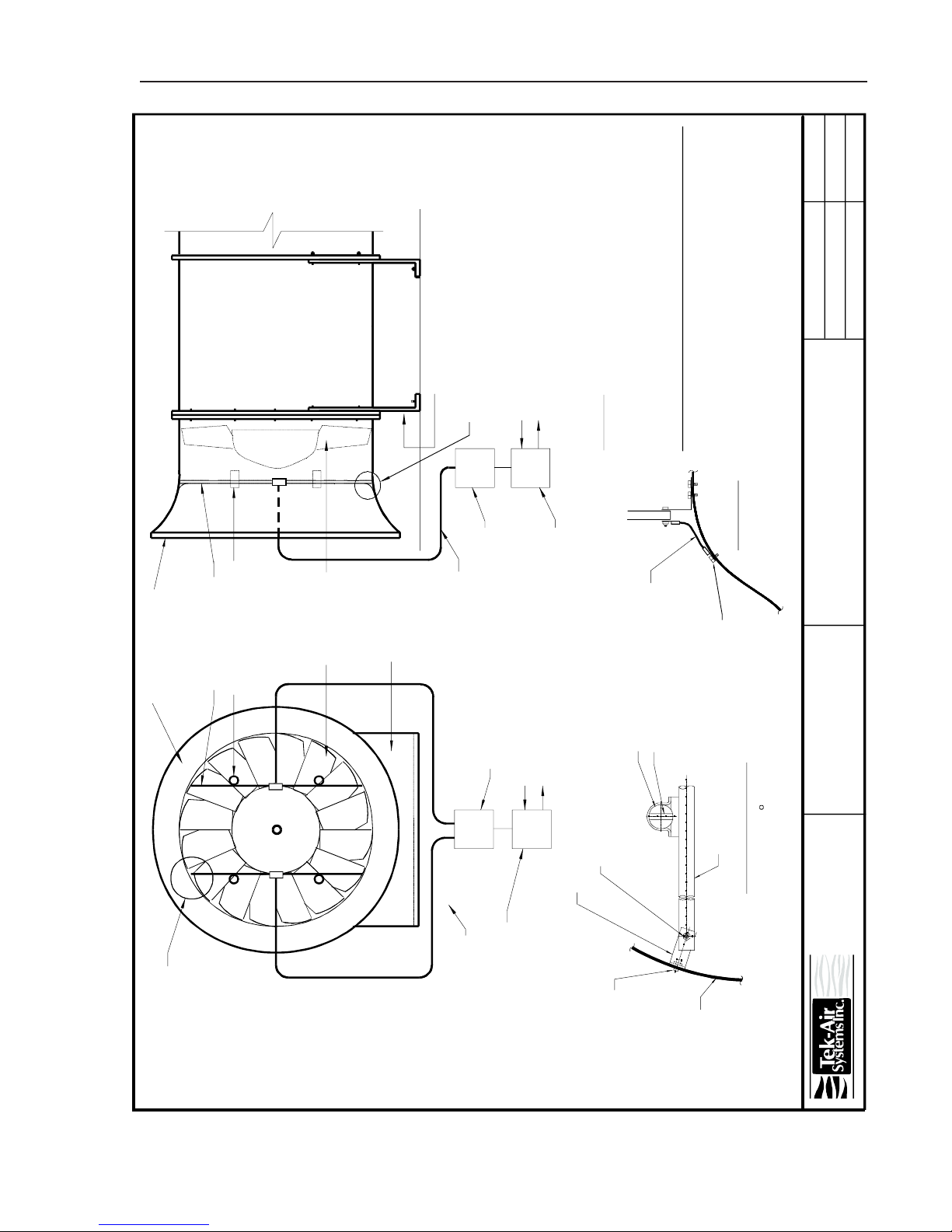
Appendices Appendix A
VORTEK SENSORS
(TYP.)
SUPPORT BAR
FANINLET BELL
FAN BLADES
FRAME
FRAME
TRANSMITTER
24 VAC
4-20 MA. OUTPUT
NON-METALLIC CONDUIT
TRANSMITTER
24 VAC
4-20 MA. OUTPUT
SEE DETAIL "A"
PROBE
ELECTRONICS
VORTEK
(PROVIDED)
PROBE
ELECTRONICS
VORTEK
Engineering Department
43 Beaver Brook Road
Danbury, CT 06810
(203) 791-1400 Phone
(203) 798-6534 Fax
Revision Letter: A
Dwg. No.:
Revision Date: 1/3/97
Filename: VT7100E.CDR
Drawn By: GV
NOTES:
1. USE LOCTITE ON MOUNTING BOLTS
WHEN INSTALLING UNIT.
MATERIALS OF CONSTRUCTION
SENSOR CLAMP: POLYETHYLENE
SENSOR SHROUD: ANODIZED ALUMINUM
PROBE TUBE: EXTRUDED ALUMINUM, ANODIZED
SENSOR SHEDDER BAR: ABS
MOUNTING BRACKET: GALVANIZED STEEL
BOLT& NUTS: ZINC COATED STEEL
VT-7100 Installation Drawing
Va n e - Axial
VorTek, Fan Inlet
(Less than 25“ Dia.)
SHROUD
SHEDDER BAR
ROTATED 90 CCW
INLET BELL
DIA.
#10 TEK SCREWS
SEE NOTE 1
FANINLET MOUNTING BRACKET
BOLT HEX HEAD
1/4-20 X 1 1/4" LG.
PROBE TUBE
DETAIL
A
ENLARGED VIEW
TYPICAL 4 PLACES
NON-METALLIC CONDUIT
(PROVIDED)
SAFETY
CABLE
SELF TAPPING
SCREW
(BY OTHERS)
SEE DETAIL “B”
DETAIL B
LOCATED A T
EACH END OF
PROBE
25VORTEK Doc.# VT5 OM 050499, Rel. 2.1
A-2A-6
Page 26
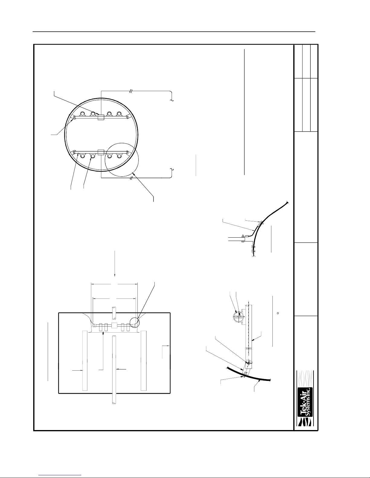
Appendices Appendix A
FAN SHAFT
L
D
VORTEK/FI
FAN SCROLL
FAN
HOUSING
SINGLE WIDTH SINGLE INLET
(SWSI) FANS
CENTRIFUGAL FAN
Engineering Department
43 Beaver Brook Road
Danbury, CT 06810
(203) 791-1400 Phone
(203) 798-6534 Fax
Revision Letter: A
Dwg. No:
Revision Date: 1/2/97
Filename: VT7200A.CDR
Drawn By: GV
VT-7200 Installation Drawing
Centrifugal (SWSI)
VorTek, Fan Inlet
(Greater than 25“ Dia.)
MATERIALS OF CONSTRUCTION
SENSOR CLAMP: POLYETHYLENE
SENSOR SHROUD: ANODIZED ALUMINUM
PROBE TUBE: EXTRUDED ALUMINUM, ANODIZED
SENSOR SHEDDER BAR: ABS
MOUNTING BRACKET : GALVANIZED STEEL
BOLT& NUTS: ZINC COATED STEEL
NOTES:
1. USE LOCTITE ON MOUNTING BOLTS
WHEN INSTALLING UNIT.
2. FOR QTY. OF SENSORS PER PROBE
SEE SCHEDULE.
SHROUD
SHEDDER BAR
ROTATED 90 CCW
INLET BELL
DIA.
#10 TEK SCREWS
SEE NOTE 1
FANINLET MOUNTING BRACKET
BOLT HEX HEAD
1/4-20 X 1 1/4" LG.
PROBE TUBE
DETAIL A
ENLARGED VIEW
TYPICAL 4 PLACES
SEE DETAIL “B”
SUPPORT BAR
PROBE
ELECTRONICS
VORTEK SENSORS
REAR (NECK) SECTION
OF BELL MOUTH SHOWN
CABLE TO TRANSMITTER
(SEE WIRING DIAGRAM)
A
SWIVEL MOUNTING
BASE (TYP.)
SELF TAPPING
SCREW
(BY OTHERS)
SAFETY
CABLE
DETAIL B
LOCATED A T
EACH END OF
PROBE
AIRFLOW
A-7
26VORTEK Doc.# VT5 OM 050499, Rel. 2.1
Page 27
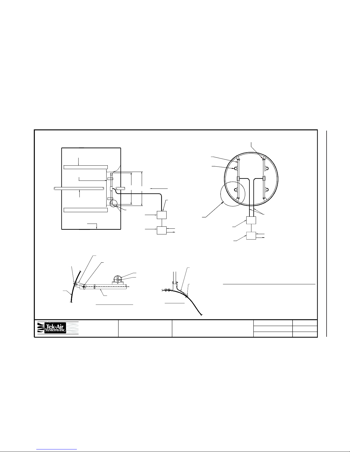
27VORTEK Doc.# VT5 OM 050499, Rel. 2.1
Appendices Appendix A
A-8
FAN SHAFT
L
D
VORTEK/FI
FAN SCROLL
FAN
HOUSING
SINGLE WIDTH SINGLE INLET
(SWSI) FANS
CENTRIFUGAL FAN
Engineering Department
43 Beaver Brook Road
Danbury, CT 06810
(203) 791-1400 Phone
(203) 798-6534 Fax
Revision Letter: A
Dwg. No.
Revision Date: 1/3/97
Filename: VT7200E.CDR
Drawn By: GV
VT-7200 Installation Drawing
Centrifugal (SWSI)
VorTek, Fan Inlet
(Less than 25“ Dia.)
NOTES:
1. USE LOCTITE ON MOUNTING BOLTS
WHEN INSTALLING UNIT.
MATERIALS OF CONSTRUCTION
SENSOR CLAMP: POLYETHYLENE
SENSOR SHROUD: ANODIZED ALUMINUM
PROBE TUBE: EXTRUDED ALUMINUM, ANODIZED
SENSOR SHEDDER BAR: ABS
MOUNTING BRACKET: GALVANIZED STEEL
BOLT & NUTS: ZINC COATED STEEL
NON-METALLIC CONDUIT
(PROVIDED)
NON-METALLIC CONDUIT
(PROVIDED)
VORTEK
TRANSMITTER
PROBE
SUPPORT BAR
SWIVEL MOUNTING
BASE (TYP.)
VORTEK SENSORS
A
ELECTRONICS
VORTEK
TRANSMITTER
PROBE
ELECTRONICS
24 VAC
4-20 MA OUTPUT
24 VAC
4-20 MA OUTPUT
SHROUD
SHEDDER BAR
ROTATED 90° CCW
INLET BELL
DIA.
#10 TEK SCREWS
SEE NOTE 1
FAN INLET MOUNTING BRACKET
BOLT HEX HEAD
1/4-20 X 1 1/4" LG.
PROBE TUBE
DETAIL A
ENLARGED VIEW
TYPICAL 4 PLACES
SELF TAPPING
SCREW
(BY OTHERS)
SAFETY
CABLE
DETAIL B
LOCATED AT
EACH END OF
PROBE
SEE DETAIL “B”
AIRFLOW
FAN SHAFT
L
D
VORTEK/FI
FAN SCROLL
FAN
HOUSING
SINGLE WIDTH SINGLE INLET
(SWSI) FANS
CENTRIFUGAL FAN
Engineering Department
43 Beaver Brook Road
Danbury, CT 06810
(203) 791-1400 Phone
(203) 798-6534 Fax
Revision Letter: A
Dwg. No.
Revision Date: 1/3/97
Filename: VT7200E.CDR
Drawn By: GV
VT-7200 Installation Drawing
Centrifugal (SWSI)
VorTek, Fan Inlet
(Less than 25“ Dia.)
NOTES:
1. USE LOCTITE ON MOUNTING BOLTS
WHEN INSTALLING UNIT.
MATERIALS OF CONSTRUCTION
SENSOR CLAMP: POLYETHYLENE
SENSOR SHROUD: ANODIZED ALUMINUM
PROBE TUBE: EXTRUDED ALUMINUM, ANODIZED
SENSOR SHEDDER BAR: ABS
MOUNTING BRACKET: GALVANIZED STEEL
BOLT & NUTS: ZINC COATED STEEL
NON-METALLIC CONDUIT
(PROVIDED)
NON-METALLIC CONDUIT
(PROVIDED)
VORTEK
TRANSMITTER
PROBE
SUPPORT BAR
SWIVEL MOUNTING
BASE (TYP.)
VORTEK SENSORS
A
ELECTRONICS
VORTEK
TRANSMITTER
PROBE
ELECTRONICS
24 VAC
4-20 MA OUTPUT
24 VAC
4-20 MA OUTPUT
SHROUD
SHEDDER BAR
ROTATED 90° CCW
INLET BELL
DIA.
#10 TEK SCREWS
SEE NOTE 1
FAN INLET MOUNTING BRACKET
BOLT HEX HEAD
1/4-20 X 1 1/4" LG.
PROBE TUBE
DETAIL A
ENLARGED VIEW
TYPICAL 4 PLACES
SELF TAPPING
SCREW
(BY OTHERS)
SAFETY
CABLE
DETAIL B
LOCATED AT
EACH END OF
PROBE
SEE DETAIL “B”
AIRFLOW
Page 28
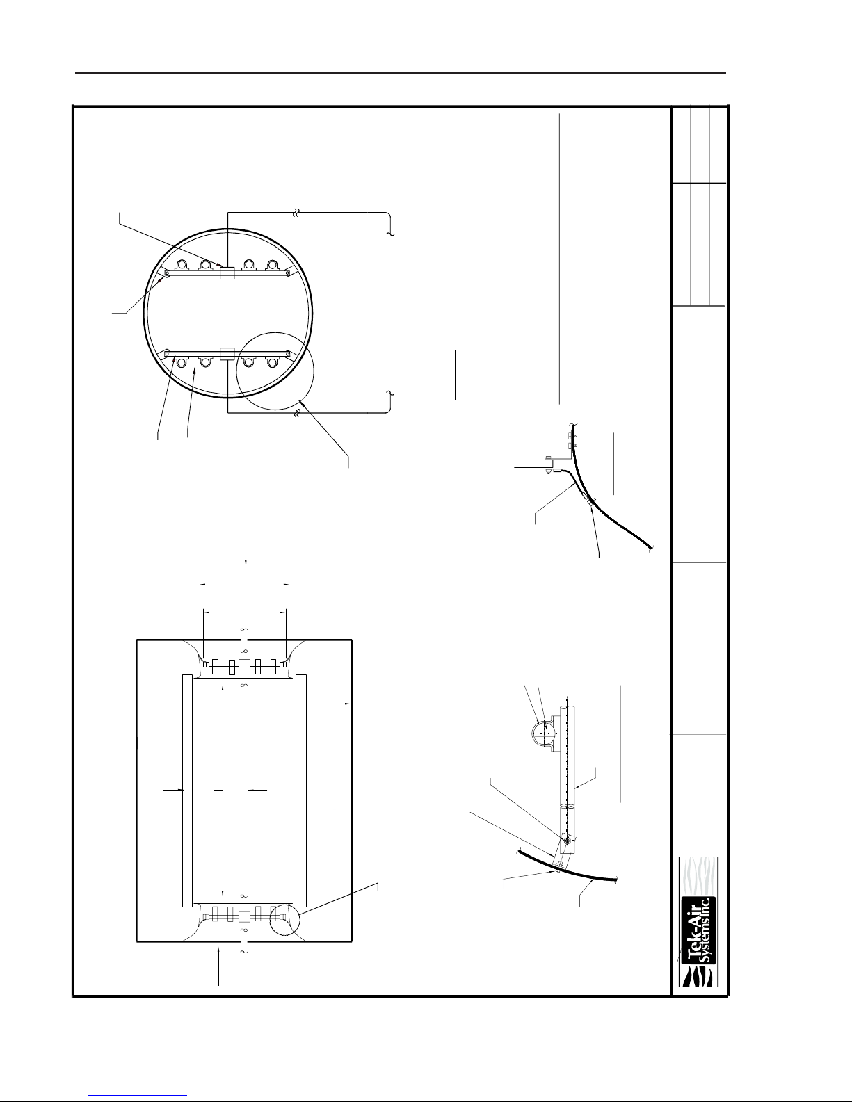
Engineering Department
43 Beaver Brook Road
Danbury, CT 06810
(203) 791-1400 Phone
(203) 798-6534 Fax
Revision Letter: A
Dwg. No:
Revision Date: 1/2/97
Filename: VT7300A.CDR
Drawn By: GV
FANSHAFT
FANSCROLL
SUPPORT BAR
SWIVEL MOUNTING
BASE (TYP.)
PROBE
ELECTRONICS
REAR (NECK) SECTION
OF BELL MOUTH SHOWN
CABLE TO TRANSMITTER
(SEE WIRING DIAGRAM)
VORTEK SENSORS
A
CENTRIFUGAL FAN
DOUBLE WIDTH DOUBLE INLET
(DWDI) FANS
L
D
VORTEK/FI
FAN HOUSING
VT-7300 Installation Drawing
Centrifugal (DWDI)
VorTek, Fan Inlet
(Greater than 25“ Dia.)
MATERIALS OF CONSTRUCTION
SENSOR CLAMP: POLYETHYLENE
SENSOR SHROUD: ANODIZED ALUMINUM
PROBE TUBE: EXTRUDED ALUMINUM, ANODIZED
SENSOR SHEDDER BAR: ABS
MOUNTING BRACKET: GALVANIZED STEEL
BOLT & NUTS: ZINC COATED STEEL
NOTES:
1. USE LOCTITE ON MOUNTING BOLTS
WHEN INSTALLING UNIT.
2. FOR QTY. OF SENSORS PER PROBE
SEE SCHEDULE.
SHROUD
SHEDDER BAR
ROTATED 90° CCW
INLET BELL
DIA.
#10 TEK SCREWS
SEE NOTE 1
FA NINLET MOUNTING BRACKET
BOLT HEX HEAD
1/4-20 X 1 1/4" LG.
PROBE TUBE
DETAIL
A
ENLARGED VIEW
TYPICAL 4 PLACES
SAFETY
CABLE
SELF TAPPING
SCREW
(BY OTHERS)
DETAIL B
LOCATED A T
EACH END OF
PROBE
SEE DETAIL “B”
AIRFLOWAIRFLOW
AIRFLOWAIRFLOW
Appendices Appendix A
28VORTEK Doc.# VT5 OM 050499, Rel. 2.1
A-9
Page 29
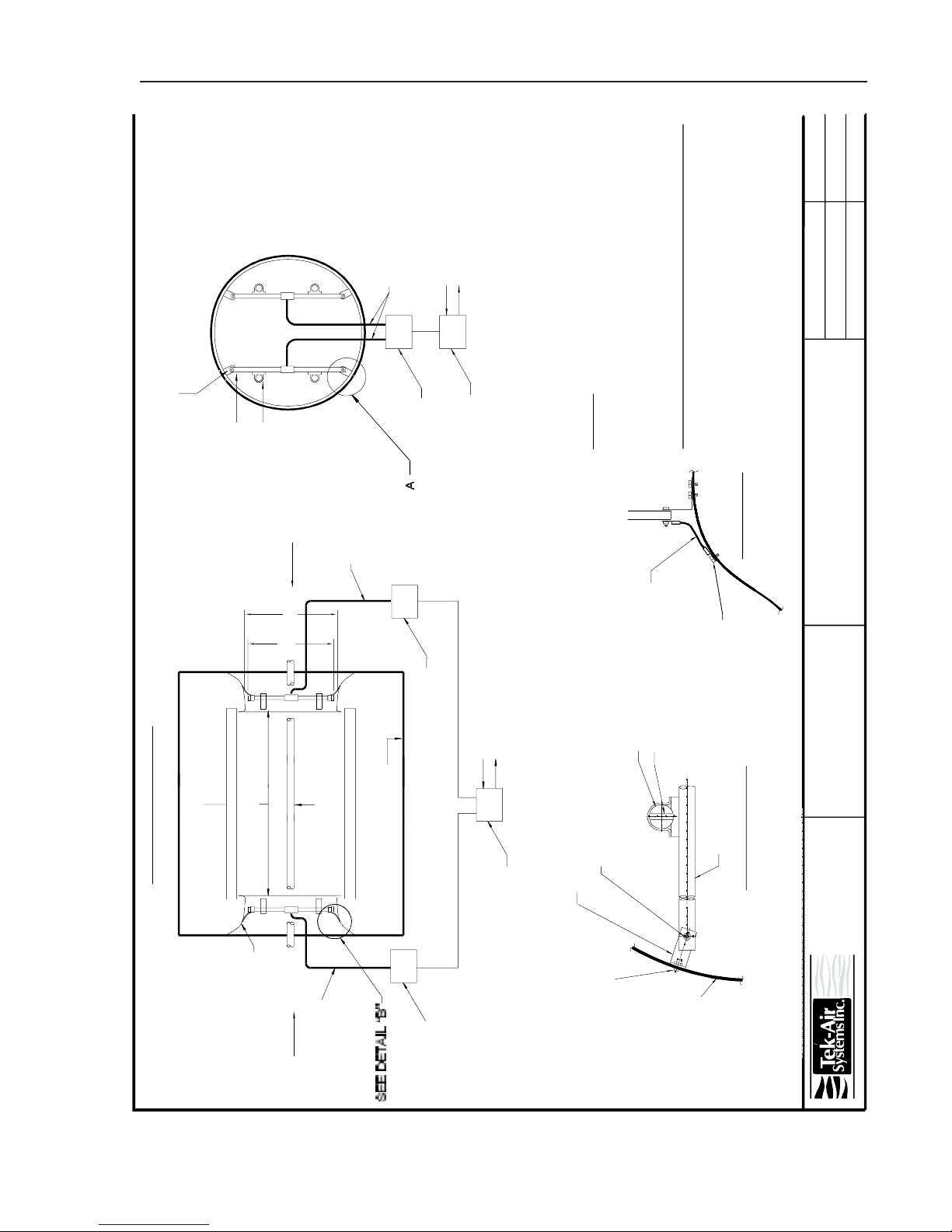
REAR (NECK) SECTION
OF BELL MOUTH SHOWN
VORTEK
SENSORS
(AS REQ'D)
SWIVEL MOUNTING
BASE (TYP.)
SUPPORT BAR
NON-METALLIC CONDUIT
(PROVIDED)
NON-METALLIC
CONDUIT
(PROVIDED) NON-METALLIC
CONDUIT
(PROVIDED)
24 VAC
24 VAC
4-20 MA OUTPUT
4-20 MA OUTPUT
VORTEK
VORTEK
TRANSMITTER
TRANSMITTER
PROBE
PROBE
INLET CONE
FAN SCROLL
VORTEK / FI
FANSHAFT
FAN HOUSING
PROBE
ELECTRONICS
ELECTRONICS
ELECTRONICS
Engineering Department
43 Beaver Brook Road
Danbury, CT 06810
(203) 791-1400 Phone
(203) 798-6534 Fax
Revision Letter: A
Dwg. No:
Revision Date: 1/2/97
Filename: VT7300D.CDR
Drawn By: GV
CENTRIFUGAL FAN
L
D
NOTES:
1. USE LOCTITE ON MOUNTING BOLTS
WHEN INSTALLING UNIT.
MATERIALS OF CONSTRUCTION
SENSOR CLAMP: POLYETHYLENE
SENSOR SHROUD: ANODIZED ALUMINUM
PROBE TUBE: EXTRUDED ALUMINUM, ANODIZED
SENSOR SHEDDER BAR: ABS
MOUNTING BRACKET: GALVANIZED STEEL
BOLT & NUTS: ZINC COATED STEEL
VT-7300 Installation Drawing
Centrifugal (DWDI)
VorTek, Fan Inlet
(Less than 25" Dia.)
SHROUD
SHEDDER BAR
ROTATED 90° CCW
INLET BELL
DIA.
#10 TEK SCREWS
SEE NOTE 1
FA NINLET MOUNTING BRACKET
BOLT HEX HEAD
1/4-20 X 1 1/4" LG.
PROBE TUBE
ENLARGED VIEW
TYPICAL 4 PLACES
DETAIL A
SELF TAPPING
SCREW
(BY OTHERS)
SAFETY
CABLE
DETAIL B
LOCATED AT
EACH END OF
PROBE
AIRFLOWAIRFLOW
AIRFLOWAIRFLOW
Appendices Appendix A
29VORTEK Doc.# VT5 OM 050499, Rel. 2.1
A-10
Page 30

Appendices Appendix B
Proper procedure for the cleaning of VorTek Airflow Measuring Probes
The Tek-Air Systems, Inc. VorTek Airflow Measuring Probe is a very versatile flow
measuring station that is used in many types of applications. Some of these applications include use in harsh environments such as pharmaceutical pill coating
areas, dirty exhaust systems, etc. In some instances the VorTek flow stations
may become fouled and require some careful cleaning to insure their long-term
operation. These cleaning tips and concerns are detailed below:
1) The VorTek probe(s) must first be carefully removed from the ductwork noting
the orientation of the sensors.
a) VorTek VT-2000 (Small Duct) - The transmitter is attached to the probe bar
with flexible hose which can not be disassembled and must be removed as a
complete unit.
b) VorTek S (Standard) - The probe bar(s) may be disconnected from the trans-
mitter simply by pulling off the connector from the microphone board, and undoing the romex connection on the enclosure.
2) The probes then can be evaluated as to the extent of fouling buildup and the
composition of the buildup.
a) Buildup of the non-hardening type, such as dust and fiber collection, can be
simply blown off using compressed air.
Note: EXTREME CAUTION MUST BE USED WHEN CLEANING WITH COM-
PRESSED AIR. THIS INCLUDES MAKING SURE THAT THE FULL PRESSURE
OF THE AIR (NOT TO EXCEED 20 PSI) IS NEVER DIRECTLY AIMED IN THE
BACK OF THE SENSOR IN THE SMALL SENSOR TUBES AS THIS CAN DAMAGE THE PROBE.
b) Buildup including both the hardening and non-hardening type can be cleaned
by first removing as much as possible with compressed air. The remaining
buildup may be removed with combinations of alcohol, compressed air, and possibly the use of a lint free cloth. When “wiping” with a cloth, caution must be
taken so as not to push any fouling agent into the sensing tubes located at the
back of the sensors. If these holes are plugged to any extent, improper readings
will be observed.
Water is not usually recommended for cleaning VorTek probes due to the fact
that the sensor tubes may become entrained with fluid and block the sensor.
30VORTEK Doc.# VT5 OM 050499, Rel. 2.1
B-1
Page 31

Page 32

41 EAGLE ROAD DANBURY, CT 06810 TEL. (203) 791-1400 FAX (203) 798-6534 WWW.TEK-AIR.COM
 Loading...