

Page 1

INSTRUCTION MANUAL UK (pag. 2)
NOTICE D’ UTILISATION FR
TB95C31X 40297200
TB95C31W 40297201
(pag. 8)
COD. 310474
Page 2

INSTALLATION, MAINTENANCE AND USE INSTRUCTIONS FOR
READ THE INSTRUCTION BOOKLET BEFORE INSTALLING AND USING THE APPLIANCE.
The manufacturer will not be responsible for any damage to property or to persons caused by incorrect installation or
improper use of the appliance.
The manufacturer is not responsible for any inaccuracies, due to printing or transcription errors, contained in this booklet. In
addition, the appearance of the figures reported is also purely indicative.
The manufacturer reserves the right to make changes to its products when considered necessary and useful, without affecting
the essential safety and operating characteristics.
Before connecting the appliance to the gas network, make sure that the data on the label attached to the food warmer
drawer or on the back of the cooker are compatible with what is indicated for the gas distribution network.
A label attached to the last page of this handbook and in the food warmer drawer (or on the back) of the appliance
indicates the appliance adjustment conditions: type of gas and operating pressure.
IMPORTANT: This appliance must be installed in compliance with current national standards in force and used only in
a well-ventilated room.
WARNING: It should be recalled that the appliance utilises a threaded 1/2" gas cylindrical male fitting according to UNIISO 228-1.
To connect the appliance to the gas network with a flexible rubber hose, a supplemental hose nipple fitting is needed
(see Fig. 1) which is supplied with the appliance.
Before performing any maintenance operation, disconnect the appliance from the gas supply and electricity network.
REPLACING THE NOZZLES TO OPERATE WITH ANOTHER TYPE OF GAS:
Follow the instructions below to change the burner nozzles on the work surface:
1) Pull out the plug from the electric outlet to avoid any type of electric contact.
2) Remove the grids from the work surface (Fig. 2).
3) Remove the burners (Fig. 2).
4) Unscrew the nozzles using a 7 mm spanner, and replace them (Fig. 3) with those needed for the new type of gas according
to what is indicated in Table 1.
Follow the instructions below to change the oven burner nozzle:
1) Remove the oven level (Fig. 4-5).
2) Loosen the screw V and pull out the burner from the support being careful not to damage the ignition plug and the
thermocouple (Fig. 6).
3) Unscrew the nozzle R (Fig. 6) using a 10 mm spanner and replace it with the nozzle needed for the new type of gas
according to what is indicated in Table 1.
Follow the instructions below to change the grill burner nozzle:
1) Loosen the screw at the end of the grill burner and pull out the burner from the support being careful not to damage the
ignition plug and the thermocouple (Fig. 7).
2) Unscrew the nozzle C (Fig. 7) using a 7 mm spanner and replace it with the nozzle needed for the new type of gas according
to what is indicated in Table 1.
WARNING: After completing the above-mentioned replacements, the technician must adjust the burners, as described
in the paragraph below, seal any adjustment and pre-adjustment devices and apply the label on the
appliance, to replace the existing one, corresponding to the new gas adjustment. This label is contained in
the spare nozzle bag.
Table 1
Burner Types of gas Pressure Nozzle diameter Rater capacity
mbar 1/100 mm. g/h l/h kW kcal/h
Auxiliary Natural G20 20 72 - 95 1 860
Butane G30 30 50 73 - 1 860
Propane G31 37 50 71 - 1 860
Semi-rapid Natural G20 20 97 - 167 1,75 1505
Butane G30 30 65 127 - 1,75 1505
Propane G31 37 65 125 - 1,75 1505
Rapid Natural G20 20 115 - 286 3 2580
Butane G30 30 85 218 - 3 2580
Propane G31 37 85 214 - 3 2580
Fish Natural G20 20 120 - 276 2,9 2494
Butane G30 30 85 211 - 2,9 2494
Propane G31 37 85 207 - 2,9 2494
Double Natural G20 20 131 - 334 3,5 3010
Ring Butane G30 30 95 254 - 3,5 3010
Propane G31 37 95 250 - 3,5 3010
FREE-STANDING COOKERS 90x60 cm GIANT OVEN
THIS APPLIANCE HAS BEEN DESIGNED FOR NON-PROFESSIONAL DOMESTIC USE.
INSTALLER TECHNICAL MANUAL
APPLIANCE GAS CONNECTION
ADAPTATION TO DIFFERENT TYPES OF GAS
2
Page 3

Oven Natural G20 20 135 - 352 3,7 3182
Butane G30 30 90 269 - 3,7 3182
Propane G31 37 90 264 - 3,7 3182
Grill Natural G20 20 115 - 191 2 1720
Butane G30 30 68 145 - 2 1720
Propane G31 37 68 143 - 2 1720
BURNER ADJUSTMENT
1) Burner "MINIMUM" adjustment:
Work surface burner adjustment: follow the instructions below to adjust the work surface burner minimum:
1) Light the burner and set the knob to the MINIMUM position (small flame).
2) Remove the knob of the valve that is press fit on the rod of that valve.
3) The cooker is equipped with safety valves, use a small slotted screwdriver on the valve body (see fig. 8) and turn the choke
screw to the right or left until the burner flame is adjusted to minimu
4) Make sure that the flame does not go out when switching quickly from the MAXIMUM to the MINIMUM position.
Oven burner adjustment: follow the instructions below to adjust the minimum:
1) Light the burner setting the knob to the MAXIMUM position.
2) Close the oven door and operate the oven for at least 10 minutes.
3) Set the knob to the MINIMUM position (corresponding to 120°) and then remove it.
4) With a slotted screwdriver turn the choking screw (see figure 9) and, while observing the flame at the same time through the
cooker porthole, evaluate the consistency of the flame so it remains on when switching quickly from the MINIMUM to the
MAXIMUM position.
Grill burner adjustment: follow the instructions below to adjust the minimum:
1) Light the burner setting the knob to the MAXIMUM position.
2) Close the oven door and operate the oven for at least 10 minutes.
3) Set the knob to the MINIMUM position (small flame) and then remove it.
4) The cooker is equipped with safety valves, use a small slotted screwdriver on the valve body (see fig. 8) and turn the choke
screw to the right or left, while observing the flame at the same time through the cooker porthole, evaluate the consistency of
the flame so it remains on when switching quickly from the MINIMUM to the MAXIMUM position.
WARNING: The above-mentioned adjustment should be made only with natural gas burners, while for those operating
with liquid gas the screw must be locked at the end in a clockwise direction.
WARNING: For the model with single grill burner, the grill burner always operates at maximum and therefore no
minimum adjustment is required.
APPLIANCE ELECTRIC CONNECTION:
The electric connection must comply with the current legal standards and regulations.
Before making the connection, check that:
- The system electrical rating and the current outlets are adequate for the maximum power output of the appliance (see the label
applied to the bottom of the casing).
- The outlet or the system is equipped with an efficient ground connection in accordance with the current legal standards and
regulations. The company will not be responsible for the non-compliance with these instructions.
When the connection to the power supply network is made using an outlet:
- If the power cord is supplied without a plug, apply a standard plug that is suitable for the load indicated on the label. Connect
the wires according to the diagram shown in FIG.10 and check that:
letter L (phase) = brown wire;
letter N (neutral) = blue wire;
ground symbol = green-yellow wire;
- The power cord must be positioned so that an overtemperature of 75 K will not be reached at any point.
- Do not use reductions, adapters or splitters since they might cause false contacts and lead to dangerous overheating.
When the connection is made directly to the electric network:
- Insert an omnipolar circuit-breaker between the appliance and the network which is sized for the appliance load with a
minimum opening between the contacts of 3 mm.
- Remember that the ground wire must not be interrupted by the circuit-breaker.
- As an alternative, the electric connection can also be protected by a high-sensitivity residual current circuit-breaker.
- It is highly recommended to attach the special green-yellow ground wire to an efficient ground system.
3
Page 4

APPLIANCE MAINTENANCE
REPLACING PARTS
Before performing any maintenance operation, disconnect the appliance from the gas supply and electricity network.
To replace parts such as knobs and burners, just remove them from the seats without disassembling any part of the cooker.
To replace parts such as nozzle supports, valves and electric components follow the procedure described in the burner
adjustment paragraph. To replace the valve or the gas thermostat, it is also necessary to disassemble the two rear gas train
brackets, loosening the 4 screws (2 per bracket) that attach it to the rest of the cooker and, unscrew the nuts that attach the
front burner valves to the control support, after removing all the knobs. To replace the gas or electric thermostat, also
disassemble the rear cooker guard, loosening the relative screws, to be able to pull out and reposition the thermostat bulb.
To replace the oven bulb, just unscrew the protection cap that projects out inside the oven.(fig.11)
WARNING: Before replacing the bulb, disconnect the appliance from the electric power supply.
Greasing the valves:
If it becomes difficult to operate the valve, it should be greased immediately by following the instructions listed below:
1) Disassemble the valve body by loosening the two screws located on the body of the valve (fig.12).
2) Extract and clean the seal cone and its housing with a rag soaked with thinner.
3) Lightly grease the cone with a special grease.
4) Insert the cone, moving it several times, remove it again, remove the excess grease and make sure that the gas passage
ways are unobstructed.
5) Replace all the pieces by reversing the order in which they were disassembled and check that the valve operates correctly.
USE AND MAINTENANCE MANUAL
GAS BURNER DIMENSION
Burner Dimension (mm)
Auxiliary Ø 50
Semi-rapid Ø 70
Rapid Ø 95
Fish 55x230
Ultra-rapid Ø 130
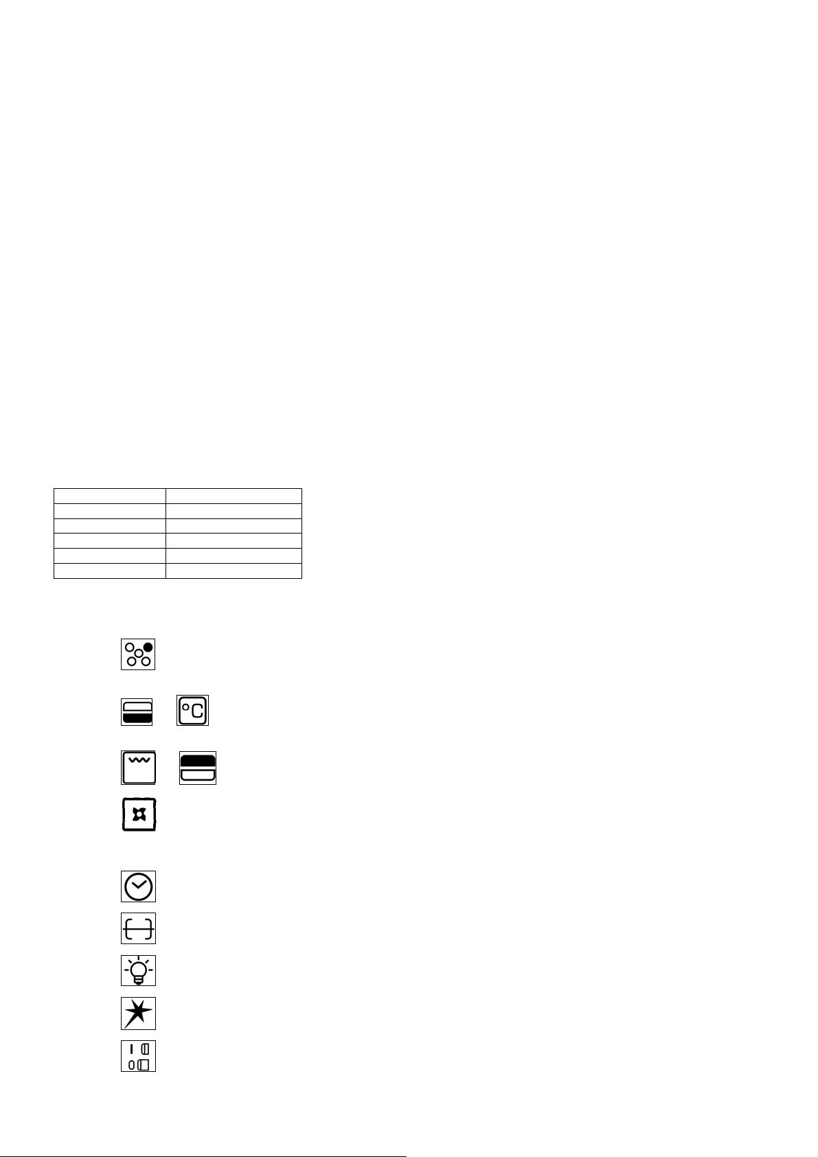
CONTROL PANEL DESCRIPTION
On the control panel, small symbols show the function of each knob or key. Here as follows are the several controls
that a cooker can have:
the symbol
rear burner on the right).
the symbol or shows the running of any oven (gas oven, gas oven with gas grill, gas oven with electric grill, static
oven, 9 positions switch)
the symbol or shows the grill (gas grill, electric grill)
the symbol shows the oven fan working button as to allow the oven to operates with fan assisted gas. The fan operation
of the oven prevents the operation of the grill, which therefore cannot be used with the fan in action.
the symbol shows the minute minder
the symbol shows the operating key for the rotisserie (only gas oven)
the symbol shows the ignition key for the oven light (all except the electric fan oven)
shows the disposition of burners on the worktop, the full dot identifies the burner in object (in this case the
the symbol shows the push-button for burner ignition
the symbol shows if keys are in position “on” or “off”
4
Page 5

USING BURNERS
A diagram is etched on the control panel above each knob which indicates which burner corresponds to that knob. The burners
can be ignited in different ways depending on the type of appliance and its specific characteristics:
- Manual lighting (it is always possible even when the power is cut off): Turn the knob counterclockwise that corresponds
to the burner selected, setting it to the MAXIMUM position at the etched star (large flame Fig.14-15-16) and place a lit match up
to the burner.
- Electric ignition: Turn the knob counterclockwise that corresponds to the burner selected, setting it to the MAXIMUM position
(large flame Fig. 14-15-16) and keep on pressing the knob in correspondence of the ignition symbol marked with a star (for
cookers equipped with ignition trough knob) or press the ignition button marked with a star and release it as soon as the burner
has ignited.
- Burner ignition equipped with safety device (thermocouple)(fig.13): Press and turn the knob counterclockwise that
corresponds to the burner selected, setting it to the MAXIMUM position at the etched star (large flame Fig. 14-15-16), press the
knob and activate one of the above-mentioned ignition devices. Once ignited, keep pressing the knob for about 10 seconds to
allow the flame to heat the thermocouple. If the burner goes out after releasing the knob, repeat the entire operation.
Note: It is recommended not to try to ignite a burner if the relative flame cap is not in the correct position.
Tips for using burners correctly:
- Use suitable pots for each burner (see tab. 3 and Fig.17).
- When the liquid is boiling, turn the knob to the MINIMUM position (small flame Fig. 14-15-16).
- Always use pots with a cover.
TABLE N°3: Recommended pot diameters.
BURNER Recommended POT DIAMETERS (cm.)
Auxiliary 12 – 14
Semi-rapid 14 – 26
Rapid 18 – 26
Double ring 22 – 26
WARNING: Use flat-bottomed containers
WARNING: After cleaning, make sure head “B” and covers “A” are properly placed on their seat as figure 18A and not
off-center as in figure 18B
WARNING: If the power is cut off, the burners can be lit with matches. When cooking foods with oil and fat, which are
very flammable, the user should not leave the appliance unattended. If the appliance is equipped with a
glass cover, such a cover may break when heated. Turn off all burners before lowering the cover. Do not
use sprays near the appliance when it is being used.
When using the burners, make sure that the handles of the pots are correctly positioned. Keep children
away from the appliance. If equipped with a cover, before being closed, any food deposits should be
cleaned off the built-in surface.
NOTE: The use of a gas cooking appliance produces heat and humidity in the room where it is installed. Therefore,
proper aeration in the room is needed while ensuring that natural ventilation openings remain unobstructed.
Intensive and continuous use of the appliance may require additional aeration, for example by opening a
window, or more efficient aeration by increasing the power of the mechanical exhauster, if installed.
USING THE GAS OVEN FOR MODEL WITH DOUBLE CONTROLS
GAS OVEN:
All the gas oven cookers are equipped with a thermostat and safety device to adjust the cooking temperature. The oven
temperature is set by turning the knob counterclockwise to match the indicator with the temperature selected. The gas oven can
be combined with a gas grill or an electric grill. See the specific pages for use information.
When the cooker model allows the combinated use of gas oven and gas grill, the oven inner temperature is adjustable within the
limit indicated in TABLE 4.
FAN GAS OVEN:
Operating the fan of the oven by means of the appropriate switch situated on the control panel, the circulation of warm air
guarantees a uniform heat distribution. The preheating of the oven can be avoided. However for delicate baking, it is preferable
to warm the oven before introducing the baking-pan. The baking system with the fan convection changes in part the various
traditional baking notions. When roasting meat it is not necessary to turn the meat any more and for a roast on the spit, it is not
indispensable to use the spit-roaster, but is sufficient to put the meat directly on the grate.
With the use of the fan gas oven, the baking temperatures are slightly lower of about 10-15°C compared to those in use with the
traditional gas oven. The fan operation of the oven prevents the operation of the grill, which therefore cannot be used with the
fan in action.
The oven can also be used in a traditional way, (by not activating the fan) for foods requiring heat from the bottom, e.g. pizza.
WARNING: If the burner flames are extinguished accidentally, turn off the control knob and do not try to relight the
oven until after at least 1 minute.
TABLE n° 4
POSITION OF OVEN KNOB ONLY OVEN BURNER OVEN BURNER+GRILL BURNER
1=MINIMUM 120°C 200°C
8=MAXIMUM 220°C 270°C
The oven burner can be ignited in different ways:
- Manual lighting (it is always possible even when the power is cut off):
To light the oven, open the oven door and turn the knob so the no. 8 on the scale matches the indicator (fig.19-20-21). At the
same time put a lit match next to the ignition tube that is visible on the oven level (fig.22). Then press the thermostat knob (this
5
Page 6

makes the gas start to flow) and keep it pressed, after the burner has been completely lit, for 10 seconds. Release the knob and
make sure that the burner remains on, otherwise repeat the operation.
- Electric ignition (only for the models equipped with this device):
In this case, first open the oven door, then press and turn the knob to the maximum temperature setting (number 8). Then press
the thermostat knob (models with ignition trough knob). Wait about 10 seconds after the burner has been completely lit and then
release the knob. Make sure that the burner remains on, otherwise repeat the operation. As for cookers without ignition trough
knob, press the thermostat knob and the key with the spark symbol, wait about 10 seconds after the burner has been
completely lit and then release the knob. Make sure that the burner remains on, otherwise repeat the operation.
The ignition device should not be used for more than 15 seconds. If after that period the burner still has not been lit, do
not use the device and open the door of the room or wait at least 60 seconds before trying to light the oven again.
WARNING: afther lighting the oven and grill burners, please wait for 2 or 3 minutes before closing the oven door, in
order to allow the burners flamesto became stable
WARNING: when trying to light the oven, the door must always be open. When using the oven, leave the cooker cover
open to prevent it from overheating.
NOTICE: when using the oven for the first time it should be operated for 15-30 minutes at a temperature of about 250°
without cooking anything inside in order to eliminate any moisture and odours from the internal insulation.
During normal oven use, after lighting the burner and setting the desired temperature, wait about 15 minutes before putting in
any food to preheat the oven. The oven is equipped with 5 guides at different heights (fig.23) which can be used to insert
shelves or the tray. To keep the oven as clean as possible it is recommended to cook meat on the tray or on the shelf that has
been inserted inside the tray.
USING THE GAS GRILL FOR MODEL WITH DOUBLE CONTROLS
The gas grill can be combined only with the gas oven.
A diagram is etched on the control panel above each knob which indicates which burner corresponds to that knob. The gas grill
can be ignited in different ways depending on the type of appliance and its specific characteristics:
- Manual lighting (it is always possible even when the power is cut off): Just completely open the oven door, turn the knob
counterclockwise that corresponds to the gas grill, setting it to the MAXIMUM position at the etched star (large flame Fig.14-15-
16) while keeping the knob pressed and place a lit match up to the burner. Make sure that the burner is completely lit and after
about 10 seconds release the knob. Make sure that the burner remains on, otherwise repeat the operation.
- Electric ignition: In this case, completely open the oven door, press and turn the knob so that the relative symbol matches the
indicator, then press the thermostat knob (models with ignition trough knob). Wait about 10 seconds after the burner has been
completely lit and then release the knob. Make sure that the burner remains on, otherwise repeat the operation. As for cookers
without ignition trough knob, press the thermostat knob and the key with the spark symbol, wait about 10 seconds after the
burner has been completely lit and then release the knob. Make sure that the burner remains on, otherwise repeat the
operation.
WARNING: afther lighting the oven and grill burners, please wait for 2 or 3 minutes before closing the oven door, in
order to allow the burners flamesto became stable
WARNING: As with the oven, the grill must be lit with the door completely open.
The gas grill can be used to grill foods on the oven shelf or using the rotisserie.
Grilling on the shelf: In this case, the shelf supplied is placed on level 1 or 2 and the foods to be grilled are placed on top,
while the tray is inserted on the lower levels to collect the cooking juices.
Then light the grill burner according to the instructions described above.
IMPORTANT: grill foods on the shelf always with the door close.
Grilling with the rotisserie: This is used to grill with the rotating skewer. Therefore, insert the skewer holder on the side
shelves at level 3. Insert the food on the skewer and insert everything into the oven, inserting the point of the skewer into the
spindle that projects out from the rear of the oven and resting the front of the skewer into the skewer holder support (fig.24).
Afther, insert the tray into one of the lower guides, then light the grill burner according to the instructions described above and
press the button that starts the rotisserie
IMPORTANT: grill foods with the rotisserie always with the door close
WARNING: the accessible parts may become very hot while grilling. Keep children away from the appliance while
cooking.
USING THE MINUTE-MINDER
The minute-minder advises the user, with an acoustic signal, when food has been cooked, after a certain time period has
elapsed. To use the device, wind the minute-minder by turning the knob clockwise one complete turn. Then turn the knob
counterclockwise so that the indicator corresponds with the selected cooking time (fig.25-26-27).
WARNING: the acoustic signal does not stop the cooking cycle. The use must turn off the cooking cycle by hand using
the relative knobs.
6
Page 7

CLEANING THE APPLIANCE
Before cleaning the appliance, it should be disconnected from the power supply and turn off the main gas feeder valve.
Cleaning the work surface:
Periodically clean the burner heads, the enamelled steel grids, the enamelled covers and the flame caps using warm soapy
water. Then those parts should be rinsed and thoroughly dried.
Any liquid that overflows from pots must always be removed using a rag.
If it becomes difficult to open or close a valve, do not force it, but immediately request the assistance of the technical
service personnel.
Cleaning the enamelled parts:
To maintain the original features of the enamelled parts they should be cleaned frequently with soapy water. Never use abrasive
powders. Do not leave acidic or alkaline substances on the enamelled parts (vinegar, lemon juice, salt, tomato sauce, etc.) and
do not wash the enamelled parts while they are still hot.
Cleaning the STAINLESS steel parts:
Clean the parts with soapy water and then dry them with a soft cloth. The shine is maintained by periodically using special
products that generally are found in the market. Never use abrasive powders.
Cleaning the burner flame caps:
Since the flame caps are resting on the burner, to clean them just remove them from their seat and wash them with soapy
water. After they have been thoroughly dried and having checked that the holes are not clogged, they can be replaced in their
proper position.
Cleaning the inside of the oven glass:
One of the features of the oven is the possibility of removing the interior glass simply by loosening the 2 screws B (see fig. 28-
29), to clean the inside surface of the glass. This operation should be carried out while the oven is cold and with a damp cloth.
Do not use abrasives.
Cleaning the inside of the oven:
To thoroughly clean the inside of the oven, it is recommended to disassemble the door by carefully following the instructions
described below. Insert the hook C (figure 30) into the hinged sector D. Put the door in a semi-open position and using both
hands pull it towards you until it is released from the attachment. To replace the door, do the opposite making sure to insert the
two sectors F correctly. In addition, the side shelves can be removed very easily, by loosening the lock rings that attach them to
the oven.
AFTER-SALES TECHNICAL SERVICE
AND SPARE PARTS
Before leaving the factory, this appliance was tested and calibrated by skilled and qualified personnel.
Any repairs or calibration that may become necessary after leaving the factory should be performed by skilled personnel.For this
reason we advise the customer to contact the Dealer that sold the appliance or the nearest Service Centre, providing them with
information about the type of appliance and the type of problem that has occurred.If defective parts must be replaced, it is
recommended to replace them with original spare parts that are available only in our technical Service Centres and authorised
dealers.
7
Page 8

NOTICE D’INSTALLATION, D’ENTRETIEN ET MODE D’EMPLOI DE LA
LIRE ATTENTIVEMENT LE CONTENU DE CETTE NOTICE AVANT D’INSTALLER OU D’UTILISER LA
CUISINIERE.
Le fabricant décline toute responsabilité en cas de dommages à des personnes ou à des biens provoqués par une
mauvaise installation ou un usage impropre de la cuisinière.
Le fabricant ne saurait être retenu responsable des inexactitudes éventuelles dues à des erreurs d’impression ou de
transcription, contenues dans cette notice. Les dessins sont purement indicatifs.
Le fabricant se réserve le droit d’apporter les modifications qu’il jugera utiles à tout moment et sans préavis, mais sans modifier
les caractéristiques essentielles de sécurité et de fonctionnement.
Avant de procéder au raccordement de l’appareil au réseau de distribution de gaz, vérifier que les données reportées
sur l’étiquette d’identification appliquée dans le tiroir de rangement ou au dos de la cuisinière sont compatibles avec
celles du réseau de distribution de gaz. L’étiquette appliquée sur la dernière page de cette notice ou dans le tiroir de
rangement ou au dos de l’appareil reporte les conditions de réglage : type de gaz et pression d’exercice.
ATTENTION : L'installation de la cuisinière doit se conformer à la législation en vigueur dans le pays d’utilisation.
ATTENTION : le raccord d’entrée du gaz à l’appareil a un taraud cylindrique de 1/2" gas, selon la norme UNI-ISO 228-1.
Pour raccorder l’appareil au gaz avec un tuyau de caoutchouc flexible, il faut un raccord porte-caoutchouc
supplémentaire (Fig. 1) fournit avec l’appareil, en conformité à les normes nationales en vigueur.
Avant toute intervention, couper l’arrivée de gaz à l’appareil.
CHANGEMENT DES INJECTEURS POUR FONCTIONNER AVEC UN AUTRE TYPE DE GAZ :
Pour changer les injecteurs des brûleurs de la table de cuisson, opérer de la façon suivante :
1) Débrancher l’appareil pour éviter tout risque d’électrocution.
2) Enlever les grilles de la table de cuisson (Fig.2)
3) Enlever les brûleurs (Fig.2)
4) A l’aide d’une clé à 6 pans de 7 mm, dévisser les gicleurs (Fig.3) les remplacer par ceux prévus pour le nouveau type de gaz
en fonction des indications du tableau N° 1
Pour changer l’injecteur du brûleur du four, opérer de la façon suivante :
1) Retirer la sole du four (fig.4-5).
2) Dévisser la vis V et retirer le brûleur du support en veillant à ne pas endommager la bougie d’allumage et le thermocouple
(fig. 6).
3) A l’aide d’une clé à 6 pans de 10 mm remplacer le brûleur R (fig.6) par celui prévu pour le nouveau type de gaz en fonction
des indications du tableau 1.
Pour remplacer l’injecteur du brûleur du grill, intervenir de la façon suivante :
1) Dévisser la vis A e ôter le brûleur de son support tout en faisant attention à ne pas abîmer la flamme d’allumage et le
thermocouple (fig.7).
2) Utiliser la clé à tubes hexagonale de 7 mm et remplacer l’injecteur C (fig.7) par un autre adapté au nouveau type de gaz
suivant les indications du tableau 1.
ATTENTION ! Après avoir exécuté les adaptations ci-dessus, procéder au réglage des brûleurs décrit dans le
paragraphe suivant, plomber éventuellement les organes de réglage et de préréglage et appliquer une nouvelle
étiquette sur l’appareil correspondant au nouveau type de gaz. Cette étiquette se trouve dans le sachet des injecteurs
de rechange.
TABLEAU n°1
Brûleur Type de Gaz Pression Ø Injecteur Classe nominale
mbar 1/100 mm. g/h l/h kW kcal/h
Naturel G20
Auxiliaire Buthane G30
Propane G31
Naturel G20
Semi-rapide Buthane G30
Propane G31
Naturel G20
Rapide Buthane G30
Propane G31
Naturel G20
Poisson Buthane G30
Propane G31
Double Naturel G20
Couronne Buthane G30
Propane G31
CUISINIERE A GAZ 90x60cm (MODELE M9)
CET APPAREIL A ETE CONCU POUR UN USAGE DOMESTIQUE.
NOTICE TECHNIQUE DESTINEE A L’INSTALLATEUR
RACCORDEMENT DE L’APPAREIL AU RESEAU DE DISTRIBUTION DU GAZ
ADAPTATION AUX DIFFERENTS TYPES DE GAZ
20 72 - 95 1 860
30 50 73 - 1 860
37 50 71 - 1 860
20 97 - 167 1,75 1505
30 65 127 - 1,75 1505
37 65 125 - 1,75 1505
20 115 - 286 3 2580
30 85 218 - 3 2580
37 85 214 - 3 2580
20 120 - 276 2,9 2494
30 85 211 - 2,9 2494
37 85 207 - 2,9 2494
20 131 - 334 3,5 3010
30 95 254 - 3,5 3010
37 95 250 - 3,5 3010
8
Page 9

Naturel G20
Four Buthane G30
Propane G31
Naturel G20
Grill Buthane G30
Propane G31
1) Réglage de la flamme minimum des brûleurs :
Réglage des brûleurs de la table de cuisson: pour régler la flamme minimum des brûleurs de la table de cuisson, procéder
de la façon suivante :
1) Allumer le brûleur et tourner la manette sur la position de MINIMUM (petite flamme).
2) Enlever la manette du robinet fixée par simple pression.
3) A l’aide d’un petit tournevis, agir sur la vis d’étranglement située sur le corps du robinet (fig. 8) jusqu’à ce que la flamme du
brûleur soit bien réglée sur le MINIMUM.
4) S’assurer qu’en passant rapidement du MAXIMUM au MINIMUM la flamme ne s’éteigne pas.
Réglage du brûleur du four : pour régler la flamme minimum du brûleur du four, procéder de la façon suivante:
1) Allumer le brûleur et tourner la manette sur la position de MAXIMUM.
2) Fermer la porte du four et faire fonctionner le four pendant 10 minutes au moins.
3) Tourner la manette sur la position de MINIMUM (en correspondance de 120°) et la retirer ensuite.
4) A l’aide d’un petit tournevis, agir sur la vis d’étranglement (figure 9) et tout en observant la flamme à travers le hublot du
four, régler la consistance de telle façon qu’elle reste allumée en exécutant de rapides passages du MAXIMUM au
MINIMUM avec la manette.
Réglage du brûleur du grill (for grill burner avec 2 commandes) : pour régler la flamme minimum du brûleur du grill,
procéder de la façon suivante:
1) Allumer le brûleur et tourner la manette sur la position de MAXIMUM.
2) Fermer la porte du four et faire fonctionner le four pendant 10 minutes au moins.
3) Tourner la manette sur la position de MINIMUM (petite flamme) et la retirer ensuite.
1) A l’aide d’un petit tournevis, agir sur la vis d’étranglement située sur le corps du robinet (fig. 8) jusqu’à ce que la flamme du
brûleur soit bien réglée sur le MINIMUM.
2) S’assurer qu’en passant rapidement du MAXIMUM au MINIMUM la flamme ne s’éteigne pas.
ATTENTION ! Le réglage ci-dessus s’exécute seulement avec des brûleurs fonctionnant au gaz méthane, avec des
brûleurs fonctionnant au gaz liquide la vis doit être vissée à fond dans le sens des aiguilles d’une montre.
Le branchement électrique doit être exécuté conformément aux normes et à la législation en vigeur. Avant de procéder
au branchement, vérifier que :
- Le voltage électrique de l’installation et des prises de courant sont compatibles avec la puissance maximale de l’appareil (cfr.
étiquette d’identification appliquée dans la partie inférieure de la contre-porte).
- La prise ou l’installation sont reliées à la terre conformément aux normes et à la législation en vigeur. Le fabricant décline toute
responsabilité en cas de non respect de ces dispositions.
Si le branchement au réseau de distribution se fait à travers une prise :
- Appliquer au câble d’alimentation, s’il en est dépourvu, une fiche normalisée adaptée au voltage indiqué sur l’étiquette
d’identification. Brancher les fils en vous basant sur le schéma de la FIG. 10 et en respectant les indications suivantes :
lettre L (phase) = fil marron.
lettre N (neutre) = fil bleu.
pictogramme terre = fil vert-jaune.
- Le câble d’alimentation doit être positionné de telle façon qu’il n’atteigne à aucun endroit une surtempérature de 75 K.
- Ne pas utiliser de réductions, adaptateurs ou commutateurs car il pourraient provoquer de faux contacts et donc des
surchauffes dangereuses.
Lorsque le branchement se fait directement au réseau électrique :
- Interposer entre l’appareil et le réseau un interrupteur omnipolaire, dimensionné au voltage de l’appareil avec une ouverture
minimum de 3 mm entre les contacts.
- Se rappeler que le câble de terre ne doit pas être interrompu par l’interrupteur.
- Le branchement électrique peut aussi être protégé par un interrupteur différentiel à haute sensibilité.
Il est vivement conseillé de relier le fil de terre vert-jaune à une installation efficace de terre.
ATTENTION : En cas de remplacement du câble d’alimentation, il est recommandé de garder le conducteur de terre
(jaune-vert), plus long de 2 cm environ par apport aux autres conducteurs et relié à la masse.
20 135 - 352 3,7 3182
30 90 269 - 3,7 3182
37 90 264 - 3,7 3182
20 115 - 191 2 1720
30 68 145 - 2 1720
37 68 143 - 2 1720
REGLAGE DES BRULEURS
BRANCHEMENT ELECTRIQUE DE L’APPAREIL
9
Page 10
Avant toute opération d’entretien et / ou de réparation, couper l’arrivée de courant et de gaz vers l’appareil.
Pour changer les composants comme les manettes ou les brûleurs, il suffit de les extraire de leur logement sans besoin de
démonter aucune pièce de la cuisinière.
Pour changer des composants comme les supports des injecteurs, les robinets et les composants électriques, suivre la
procédure décrite dans le paragraphe du réglage des brûleurs. En cas de changement du robinet ou du thermostat gaz,
démonter aussi les deux équerres de fixation derrière la rampe, en dévissant les 4 vis (2 par équerre) qui la fixe au reste de la
cuisinière. Retirer toutes les manettes et dévisser les écrous qui fixent les robinets des brûleurs avant au support du tableau de
bord.
En cas de changement du thermostat gaz ou électrique, démonter aussi la protection arrière de la cuisinière, en dévissant les
vis correspondantes, afin de pouvoir retirer et replacer le réservoir du thermostat.
Pour changer l’ampoule du four, il suffit de dévisser la calotte de protection qui dépasse à l’intérieur du four (fig. 11).
ATTENTION ! Avant de changer l’ampoule, débrancher l’appareil.
Graissage des robinets :
Si un robinet devient trop dur à manoeuvrer, le graisser sans attendre, en suivant les indications ci-dessous :
1) Démonter le corp du robinet en dévissant les deux vis situées dessus (fig. 12).
2) Extraire et nettoyer le cône de tenue et son logement avec un chiffon imbibé de diluant.
3) Graisser légèrement le cône avec la graisse adaptée.
4) Introduire le cône, le manoeuvrer plusieurs fois, l’extraire à nouveau, enlever la graisse superflue et vérifier que les zones de
passage du gaz ne sont pas obstruées.
5) Remonter toutes les pièces dans l’ordre inverse du démontage et vérifier le bon fonctionnement du robinet.
NOTICE DE MODE D’EMPLOI ET D’ENTRETIEN MODE D’EMPLOI ET D'ENTRETIEN
DIMENSION DES BRULEURS GAZ
BRULEUR DIMENSION (mm)
Auxiliaire Ø 50
Semi-rapide Ø 70
Rapide Ø 95
Poisson 55X230
Doble Couronne Ø 130
DESCRIPTION PANNEAU DE CONTROLE
Sur le panneau de contrôle, en correspondance de chaque bouton ou touche, la function est visualisée par un petit symbol. Ci
dessous on mentionne les plusieurs commandes qu'on peut trouver sur une cuisinière:
ENTRETIEN DE L'APPAREIL
CHANGEMENT DES COMPOSANTS
le symbole indique la disposition des brûleurs sur le plan travail, le petit point plein identifie le brûleur en
examen (en ce cas le brûleur postérieur à droite)
le symbole ou indique le functionnement de n’importe quel four (four à gaz, four a gaz avec grill à gaz – four à gaz
avec grill électrique – four statique – commutateur 9 positions)
le symbole ou indique le functionnement de n’importe quel grill (grill à gaz, grill électrique )
le symbole indique la touche d'actionnement du ventilateur four pour permettre l'emploi du four à gaz ventilé. Le
fonctionnement du ventilateur empêche le fonctionnement du grill électrique, qui ne peut donc pas être utilisé avec le ventilateur
en marche.
le symbole indique le compte-minutes
le symbole indique le touche de mise en action du tournebroche (seulement four à gaz)
le symbole indique le touche d'allumage de la lumière du four (tous sauf le four électrique ventilé)
le symbole indique le bouton d'allumage des brûleurs
le symbole indique si les touches sont en position d'allumé ou éteint
10
Page 11

UTILISATION DES BRULEURS
Sur le tableau de bord, au-dessus de chaque manette, un schéma a été gravé qui indique à quel brûleur se réfère la manette.
L'allumage des brûleurs peut s’effectuer de différentes façons en fonction du type d’appareil et de ses caractéristiques
particulières :
- Allumage manuel (il est toujours possible même en cas de coupure de courant) : Tourner la manette correspondant au
brûleur sélectionné dans le sens contraire des aiguilles d’une montre et la placer sur la position de MAXIMUM (grande flamme
Fig. 14-15-16) et approcher une alumette allumée vers le brûleur.
- Allumage électrique : Tourner la manette correspondant au brûleur sélectionné dans le sens contraire des aiguilles d’une
montre et la placer sur la position de MAXIMUM (grande flamme Fig. 14-15-16) tenez le bouton appuyé en correspondance du
symbole d'allumage marqué d'une étoile (pour cuisinières douées d'allumage sous bouton) appuyer ensuite sur le bouton
d’allumage indiqué par une étoile et relâcher dès que le brûleur s’allume.
- Allumage brûleurs dotés d’un dispositif de sécurité (thermocouple)(Fig. 13): Presser et tourner la manette
correspondant au brûleur sélectionné dans le sens contraire des aiguilles d’une montre et la placer sur la position de MAXIMUM
(grande flamme Fig. 14-15-16), presser la manette et activer un des allumages décrits ci-dessus. Une fois l’allumage effectué,
continuer à presser la manette pendant 10 secondes environ de façon à laisser le temps à la flamme de chauffer le
thermocouple. Si le brûleur s’éteint après avoir relâché la manette, répéter entièrement l’opération.
N.B.: Il est recommandé de ne pas essayer d’allumer un brûleur si son chapeau n’est pas correctement mis en place.
Conseils pour la meilleure utilisation des brûleurs :
- Utiliser des récipients dont le format est adapté au brûleur (cfr. tableau n° 3 et Fig. 17).
- Lorsque l’ébulliton est atteinte, placer la manette sur le MINIMUM (petite flamme Fig. 14-15-16).
- Utiliser toujours des récipients avec couvercle.
TABLEAU N° 3
BRULEUR DIAMETRES DES RECIPIENTS CONSEILLES (cm)
Auxilliaire 12 – 14
Semi-rapide 14 – 26
Rapide 18 - 26
Double couronne 22 - 26
ATTENTION ! Utiliser toujours des récipients à fond plat.
ATTENTION ! En cas de coupure de courant, les brûleurs peuvent être allumés avec une allumette. Durant la
cuisson des aliments avec de l’huile ou autres matières grasses, facilement inflammables, l’utilisateur ne doit pas
s’éloigner de l’appareil.
Si l’appareil est doté d’un couvercle en verre, celui-ci peut éclater sous l’action de la chaleur. Eteindre donc tous les
brûleurs avant d’abaisser le couvercle. Ne pas utiliser de spray près de l’appareil lorsque celui-ci est en fonction.
Pendant l’utilisation des brûleurs, veiller à ce que les manches des récipients soient orientés vers l’intérieur. Les
enfants doivent être tenus hors de portée. Après chaque utilisation, il est recommandé de nettoyer la plaque et
d’éliminer les résidus éventuels.
NOTE: L’utilisation d’un appareil de cuisson au gaz produit de la chaleur et de l’humidité dans la pièce où il est
installé. Par conséquent la pièce doit être bien aérée et les ouvertures de la ventilation naturelle ne doivent jamais être
obstruées . Activer aussi le dispositif mécanique d’aération / hotte d’aspiration ou électroventilateur.
Une utilisation intensive et prolongée de l’appareil, peut nécessiter une aération supplémentaire, par exemple
l’ouverture d’une fenêtre, ou une aération plus efficace en augmentant la puissance de l’aspiration mécanique si elle
est prévue.
UTILISATION DU FOUR A GAZ
FOUR A GAS:
Toutes les cuisinières avec un four à gaz sont équipées d’un thermostat avec sécurité pour le réglage de la température de
cuisson. En tournant la manette dans le sens contraire des aiguilles d’une montre de façon à ce que l’indice et la température
choisie correspondent, on programme la température du four. Le four à gaz peut être combiné à un grilloir à gaz ou à un grilloir
électrique, dont l’utilisation est expliquée dans les pages correspondantes.
Quand on utilise le four a gaz combine avec le grill a gaz, a l'interieur du four les temperatures augmentent comme indique dans
le tableau 4
FOUR A GAS A CHALEUR TOURNANTE:
En actionnant le ventilateur du four par l’interrupteur approprié situé sur le tableau de commande, la circulation de l’air chaud
assure une distribution uniforme de la chaleur. Le préchauffage du four peut être évité; toutefois, pour la pâtisserie très délicate,
il est préférable de chauffeur le four avant d’y insérer les plats. Le système de cuisson à convection ventilée change
partiellement les différentes notions de cuisson traditionnelle. La viande ne doit plus être retournée pendant la cuisson et pour
obtenir un rôti à la broche il n’est plus indispensable d’utiliser le tournebroche, mais il suffit de mettre la viande directement sur
la grille.
Par l’emploi du four à gaz à chaleur tournante, les températures de cuisson sont légèrement inférieures d’environ 10-15°C par
rapport à l’utilisation du four à gaz traditionnel. Le fonctionnement du ventilateur empêche le fonctionnement du grill, qui ne peut
donc pas être utilisé avec le ventilateur en marche.
Le four peut aussi être utilisé de façon traditionnelle, (n’activant pas la ventilation) pour les aliments qui exigent la chaleur du
bas, par ex. la pizza.
ATTENTION ! Si la flamme du brûleur s’éteint accidentellement, fermer la manette d’actionnement et attendre 1 minute
au moins avant de le rallumer.
11
Page 12

TABLEAU n° 4
POSITION THERMOSTAT BRULEUR FOUR BRULEUR FOUR+BRULEUR GRILL
1=MINIMUM 120°C 200°C
8=MAXIMUM 220°C 270°C
L'allumage du brûleur du four peut s’effectuer de différentes façons :
- Allumage manuel (toujours possible mais en cas de coupure de courant) :
Ouvrir la porte du four et tourner la manette jusqu’à faire correspondre le N° 8 avec l'indice(fig.19-20-21). Approcher en même
temps une allumette allumée vers le petit tube de l’allumage visible sous la sole du four
(fig.22). Presser ensuite la manette du
thermostat (de cette façon le gaz commence à passer) et continuer à le presser 10 secondes encore après l'allumage complet
du brûleur. Relâcher la manette et contrôler si le brûleur reste allumé, sinon répéter toute l’opération.
- Allumage électrique (seulement pour les modèles équipés de ce dispositif) :
Ouvrir la porte du four. Presser et tourner ensuite la manette jusqu’à la position maximale de température (numéro 8). Presser
ensuite la manette du thermostat (pour cuisinières douées d'allumage sous bouton) Attendre 10 secondes environ après
l'allumage complet du brûleur et relâcher la manette. Contrôler si le brûleur reste allumé, sinon répéter toute l’opération.
Presser ensuite la manette du thermostat et la touche reportant le pictogramme de l’étincelle. Attendre 10 secondes environ
après l'allumage complet du brûleur et relâcher la manette. Contrôler si le brûleur reste allumé, sinon répéter toute l’opération.
Le dispositif d’allumage ne doit pas être actionné plus de 15secondes. Si après ce délai, le brûleur ne s’est pas allumé,
cesser d’appuyer sur le bouton, ouvrir la porte du four et attendre au moins 60 secondes avant de tenter un nouvel
allumage.
ATTENTION ! l'allumage du four doit toujours s’effectuer avec la porte ouverte.
ATTENTION ! avant la première utilisation, chauffer le four à vide pendant 15-30 minutes à la température de 250°
environ, afin d’éliminer l’humidité et l’odeur des matériaux internes.
Préchauffer le four pendant 15 minutes, avant d’introduire les aliments à cuire.
Le four est équipé de 5 glissières à différentes hauteurs (fig.23), dans lesquelles on peut glisser les grilles ou le plat. Pour éviter
de trop salir le four, il est conseillé de cuire l’aliment dans le plat ou sur une grille elle-même posée sur le plat. Le tableau cidessous reporte les temps de cuisson et la position indicative du plat pour les différents types d’aliments. Ces informations ne
sont données qu’à titre indicatif, et ne sauraient remplacer l’expérience ou les goûts personnels. Il est de toutes façons conseillé
de suivre les indications reportées sur le livre de recettes.
UTILISATION DU GRILL A GAZ
Le grill à gaz fonctionne exclusivement avec le four à gaz. Sur le panneau commandes au-dessus de chaque poignee il est
serographie un schema dans lequel il est indiquee le bruleur a lequel la poignee se refer.
Le grill à gaz peut être allumé de façon suivante :
Allumage manuel : Il suffit d’ouvrir complètement la porte du four, de tourner le bouton en faisant correspondre le symbole
avec le repère, et, continuant à appuyer sur le bouton, approcher une allumette au brûleur. Une fois allumé, attendre 10
secondes et relâcher le bouton. Vérifier que le brûleur est allumé ; en cas contraire, répéter l’opération.
Allumage électrique : dans ce cas, ouvrir complètement la porte du four, presser et tourner le bouton en faisant correspondre
le symbole avec le repère, presser ensuite la manette du thermostat (pour cuisinières douées d'allumage sous bouton) et tout
en le tenant enfoncé, ou appuyer sur la touche avec le symbole de l’étincelle. Une fois allumé, attendre 10 secondes et relâcher
le bouton. Vérifier que le brûleur est allumé, en cas contraire, répéter l’opération.
ATTENTION: comme pour le four, il est essentiel d’effectuer l’allumage du grill avec la porte complètement ouverte.
Le grill à gaz peut être utilisé pour griller sur la grille du four ou utilisant le tournebroche.
Grillade sur la grille : dans ce cas, placer la grille fournie avec l’appareil au niveau 1 ou 2 et poser dessus les aliments à griller.
Pour recueillir les sauces de cuisson, le plateau doit être placé aux niveaux inférieurs. Allumer ensuite le brûleur en suivant les
indications reportées ci dessus.
IMPORTANT: pour tous les modèles, la grillade sur la grille doit être toujours faite avec la porte fermée.
Grillade avec tournebroche : sa fonction est de griller en utilisant la broche rotative. Placer dans le four la tige sur les grilles
latérales au niveau 3. Enfiler les aliments sur la broche et mettre le tout dans le four, en faisant entrer la pointe dans
l’encastrement qui se trouve dans la partie arrière du four, et poser la broche dans l’emplacement prévu à cet effet(Fig. 24).
Enfiler ensuite le plateau dans une des guides inférieures, allumer le brûleur et appuyer sur la touche représentant le symbole
de la broche pour faire partir le moteur.
IMPORTANT: pour tous les modèles, la grillade sur la grille doit être toujours faite avec la porte fermée.
ATTENTION: les parties accessibles peuvent devenir très chaudes pendant les opérations de grillade. Eloigner les
enfants de la cuisine.
Le minuteur, écoulé un certain temps, averti avec un signal acoustique la fin du temps de cuisson des aliments. Il suffit de
tourner complètement le bouton dans le sens des aiguilles d’une montre (fig.25-26-27), puis de le tourner dans le sens opposé
choisissant le temps de cuisson.
ATTENTION: le signal acoustique n’arrête pas la cuisson. Pour interrompre la cuisson, il faut intervenir manuellement
en éteignant les boutons correspondants.
UTILISATION DE LA MINUTERIE
12
Page 13

NETTOYAGE DE L’APPAREIL
Débrancher l’appareil du réseau d’alimentation et fermer le robinet général d’adduction de gaz à l’appareil avant de
procéder à toute opération de nettoyage.
Nettoyage du plan de cuisson :
Les brûleurs, les grilles en acier émaillé, les couvercles émaillés, et les répartiteurs de flamme doivent être lavés
périodiquement avec de l’eau savonneuse tiède, rincés et essuyés avec soin.
L’éventuel liquide débordé des casseroles doit toujours être enlevé avec un chiffon.
Si la manœuvre d’ouverture et de fermeture d’un des robinets est difficile, ne pas insister, mais demander
l’intervention urgente de l’assistance technique.
Nettoyage des éléments émaillés :
Les parties émaillées doivent être lavées fréquemment avec de l’eau savonneuse pour en garder longtemps les
caractéristiques. Ne jamais utiliser des poudres abrasives. Eviter de laisser dessus des substances acides ou alcalines
(vinaigre, jus de citron, sel, jus de tomates, etc.) et laver les parties émaillées quand elles sont encore chaudes.
Nettoyage des parties en acier inoxydable :
Les éléments en acier inoxydable doivent être nettoyés avec de l’eau savonneuse, puis rincés avec un chiffon doux. Utiliser des
produits spécifiques que l’on trouve facilement dans le commerce pour maintenir le brillant. Ne jamais utiliser des produits
abrasifs.
Nettoyage des répartiteurs de flamme :
Etant seulement posés, il suffit de les ôter de leurs logements et de les laver avec de l’eau savonneuse. Apres les avoir bien
essuyés et vérifié que les trous de sortie ne sont pas bouchés, les replacer correctement dans leurs positions.
Nettoyage du verre à l’intérieur du four :
Le verre à l’intérieur du four peut être démonté en dévissant simplement les 2 vis B (voir Fig.28-29) pour le nettoyer. Cette
opération se fait à four froid et avec un chiffon humide, en ayant soin de ne pas utiliser des produits abrasifs.
Nettoyage intérieur du four :
Pour faciliter le nettoyage du four, démonter la porte en suivant les instructions reportées ci-dessous :
Placer le crochet C (Fig. 30) dans la charnière D. Tenir la porte à semi-ouverte et tirer vers soi avec les mains la petite porte
jusqu’à ce qu’elle se décroche. Pour la remonter, exécuter les opérations en sens inverse ayant soin d’introduire complètement
les deux secteurs F. Les grilles latérales peuvent être, elles aussi, enlevées facilement, en dévissant les embouts qui les fixent
au four.
13
Page 14

(fig.1) (fig.2) (fig.3)
(fig.4) (fig.5)
(fig.6) (fig.7)
(fig.8) (fig.9)
14
Page 15

(fig.10) (fig.11) (Fig. 12)
(Fig. 13) (Fig. 14) (Fig. 15) (Fig. 16)
(Fig. 17) Fig. 18 (fig.18A –18B)
(Fig. 19) (Fig. 20) (Fig. 21)
(Fig. 22) (Fig. 23)
15
Page 16

(Fig. 24) (Fig. 25) (F ig. 26)
(Fig. 27) (Fig. 27) (Fig. 27)
(Fig.35)
16
Page 17

Page 18

ﻚﺸﺧ مﺮﻧ ﻪﻨﻬآ ﻚﻳ ﺎﺑ ار ﺎﻬﻧﺁ و ﺪﻴهد ﻮﺸﺘﺴﺷ نﻮﺑﺎﺻ و بﺁ ﺎﺑ ار ﺎﻬﺘﻤﺴﻗ ﻦﻳا ﺪﻴﻨآ . ﻦﻳا ﺶﺸﺧرد
ﺪﻧﻮﺷ ﯽﻣ ﺖﻓﺎﻳ رازﺎﺑ رد ًﻻﻮﻤﻌﻣ ﻪآ ﯽﺗﻻﻮﺼﺤﻣ زا ﻩﺎﮔ ﻪﺑ ﻩﺎﮔ ﻩدﺎﻔﺘﺳا ﺎﺑ ﻩاﺮﻤه قﺎﺟا یﺎﻬﺘﻤﺴﻗ
ددﺮﮔ ﯽﻣ ﻦﻴﻤﻀﺗ . ﺎهردﻮﭘ زا ﺰﮔﺮه ی ﺪﻴﻨﻜﻧ ﻩدﺎﻔﺘﺳا بﺎﺳ .
ﺎه ﻪﻠﻌﺷ ﻦآ ﺶﺨﭘ ﻪﻠﻌﺷ ﺖﻤﺴﻗ ندﺮآ ﺰﻴﻤﺗ :
ﺰﻴﻤﺗ یاﺮﺑ ، ﺪﻧا ﻪﺘﻓﺮﮔ راﺮﻗ ﺎه ﻪﻠﻌﺷ یور ﯽﮔدﺎﺳ ﻪﺑ ﻪآ ﯽﻳﺎﺠﻧﺁ زاندﺮآﺖﺳا مزﻻ زا ار ﺎﻬﻧﺁ
ﺪﻴﺋﻮﺸﺑ نﻮﺑﺎﺻ و بﺁ ﺎﺑ و ﻪﺘﺷادﺮﺑ دﻮﺧ ﻞﺤﻣ . ﻪآ ﺪﻴﻨآ لﺮﺘﻨآ ﺎﻬﻧﺁ ﻞﻣﺎآ ندﺮآ ﻚﺸﺧ زا ﺲﭘ
ﺪﻴهد راﺮﻗ دﻮﺧ ﻞﺤﻣ یور ﯽﺘﺳرد ﻪﺑ ارﺎﻬﻧﺁ و ﺪﺷﺎﺑ ﻩﺪﺸﻧ ﻪﺘﻓﺮﮔ ﺎﻬﻧﺁ ﻚﭼﻮآ یﺎﻬﺧارﻮﺳ .
ﺮﻓ ﯽﻠﺧاد ﻪﺸﻴﺷ ندﺮآ ﺰﻴﻤﺗ :
ﺮﻓ تﺎﻴﺻﻮﺼﺧ زا ، ﺎﺑ نﺁ ﯽﻠﺧاد ﻪﺸﻴﺷ ﻦﺘﺷادﺮﺑ نﺎﻜﻣا ﺪﺷﺎﺑ ﯽﻣ ﭻﻴﭘ ود ندﺮآ زﺎﺑ
ﺪﻴﻨﻜﻧ ﻩدﺎﻔﺘﺳا بﺎﺳ صﻮﺼﺨﻣ داﻮﻣ زا ﺪﻴﻨآ ﺖﻗد ﺪﺷﺎﺑ ﯽﻣ دﺮﺳ ﺮﻓ ﻪآ دﺮﻴﮔ مﺎﺠﻧا .
ﺮﻓ ﻞﺧاد ندﺮآ ﺰﻴﻤﺗ:
اﺮﺑیﺗ ﻬﺴ ﻪﺑ ﻪﺟﻮﺗ ﺎﺑ ار ﺮﻓ رد ﺖﺳا ﺮﺘﻬﺑ ﺮﻣا ﻦﻳا ندﻮﻤﻧ ﻞﻴ دروﺁرد ﺮﻳز تارﻮﺘﺳد ، ﻩ لﺎﺼﺗا C
ﻻﻮﻟ ﺖﻤﺴﻗ رد اری D ﺪﻴﻨآ دراو )ﺮﻳﻮﺼﺗ 30 ( ﺖﺳد ﺎﺑ و ﺪﻴهد راﺮﻗ زﺎﺑ ﻪﻤﻴﻧ ﺖﻴﻌﺿو رد ار رد
ﺑ اﺮﻧﺁﺴ ﺘﻗو ﺎﺗ ﺪﻴﺸﻜﺑ دﻮﺧ ﺖﻤﯽ دﻮﺷ دازﺁ ﻩﺮﻴﮔ زا ﻪآ .اﺮﺑی ﺲﻜﻋﺮﺑ ﺖﺳرد رد ﻦﺘﺧاﺪﻧا ﺎﺟ
ﺖﻤﺴﻗ ود ﺎﺗ ﺪﺷﺎﺑ ﺐﻗاﺮﻣ و ﺪﻴﻨآ ﻞﻤﻋ ﻻﺎﺑ دراﻮﻣF ﻴﺑ ﺎﺟ ﯽﺘﺳرد ﻪﺑار ﺪﻳزاﺪﻨ . ﻦﻳاﺮﺑ ﻩوﻼﻋ
ﮔدﺎﺳ ﻪﺑ ﯽﺒﻧﺎﺟ یﺎﻬﻠﻳﺮﮔ دراﻮﻣﯽ ﺰﻠﻓ ﻚﭼﻮآ ﻪﻘﻠﺣ نﺪﻧﺎﭽﻴﭘ ﺎﺑ ی ﻣ ﻞﺼﺘﻣ ﺮﻓ ﻪﺑ اﺮﻧﺁ ﻪآ ﯽ زﺎﺑ ﺪﻨﻨآ
) ﺮﻳﻮﺼﺗ 28-29 ( دﺮآ ﺰﻴﻤﺗ اﺮﻧﺁ ﻞﺧاد ناﻮﺘﺑ ﺎﺗ . ﻧﺎﻣز طﻮﺑﺮﻣ ﻪﻨﻬآ ﻚﻳ ﺎﺑ ﺪﻳﺎﺑ تﺎﻴﻠﻤﻋ ﻦﻳاﯽ
ﻣﯽ ﺪﻧﻮﺷ .
ﻠﻴﻤﻜﺗ تﺎﻣﺪﺧﯽآﺪﻳ تﺎﻌﻄﻗ و شوﺮﻓ زا ﺲﭘ ﯽ
راﺮﻗ ﯽﺳرزﺎﺑ درﻮﻣ سﺎﻨﺷرﺎآ و ﺺﺼﺨﺘﻣ داﺮﻓا ﻂﺳﻮﺗ زﺎﮔ قﺎﺟا ، ﻪﻧﺎﺧرﺎآ زا جوﺮﺧ زا ﻞﺒﻗ
ﺪﺷ ﺖﺴﺗ و ﺖﺳا ﻪﺘﻓﺮﮔ ﺖﺳا ﻩ . دﻮﺷ مزﻻ ًا ﺪ ﻌ ﺑ ﻪآ ﯽﺘﺴﺗ و ﺮﻴﻤﻌﺗ ﺮه ﻦﻳاﺮﺑ ﺎﻨﺑ
دﺮﻴﮔ مﺎﺠﻧا ﺺﺼﺨﺘﻣ داﺮﻓا ﻂﺳﻮﺗ ﺪﻳﺎﺑ ﯽﻣ . ﻪﺑ ﺎﻳ و ﻩﺪﻨﺷوﺮﻓ ﻪﺑ ﻢﻴﻨآ ﯽﻣ ﻪﻴﺻﻮﺗ ﺎﻤﺸﺑ ﻦﻳاﺮﺑ ﺎﻨﺑ
تاﺮﻴﻤﻌﺗ زﺎﺠﻣ ﺰآﺮﻣ ﻦﻳﺮﺗ ﻚﻳدﺰﻧ ﺪﻴﻨﮐ ﻪﻌﺟاﺮﻣ و ﺪﻳراد ﯽﻗﺎﺟا عﻮﻧ ﻪﭼ ﺪﻴهد عﻼﻃا ﺎﻬﻧﺁ ﻪﺑ و
ﺖﺳا ﻩﺪﻣﺁ ﺶﻴﭘ ﯽﻠﻜﺸﻣ ﻪﭼ .
ترﻮﺻ رد آﺪﻳ تﺎﻌﻄﻗ ﺎﺑ ار ﺎﻬﻧﺁ دﻮﺷ ﯽﻣ ﻪﻴﺻﻮﺗ تﺎﻌﻄﻗ ﺾﻳﻮﻌﺗﯽ ﻂﻘﻓ ﻪآ ﺪﻴﻨآ ضﻮﻋ ﻞﺻا
ﺪﻨﺘﺴه دﻮﺟﻮﻣ ﻩﺪﻧزﺎﺳ ﺖآﺮﺷ ﺰآاﺮﻣ و زﺎﺠﻣ ﺮﻴﻤﻌﺗ ﺰآاﺮﻣ رد .
Page 19

ﺮآ ﯽﺑﺎﺒآ ﻞﻳﺮﮔ یور ﺮﺑ ند : یور ﺮﺑ و ﻪﺘﺷاﺬﮔ نﺁ صﻮﺼﺨﻣ یﺎﺟ رد ار ﻞﻳﺮﮔ ترﻮﺼﻨﻳا رد
راﺮﻗ ار ﯽﻨﻴﺳ ﻦﻳﺮﻳز حﻮﻄﺳ یور رد ﻪآ ﯽﻟﺎﺣ رد ، ﺪﻴهد راﺮﻗ ار ﯽﻳاﺬﻏ داﻮﻣ نﺁ
ﭘ و ﺖﺨﭘ زا ﻞﺻﺎﺣ تﺎﻌﻳﺎﻣ ﺎﺗ ﺪﻳا ﻩدادﺰ ﺪﻨآ یروﺁ ﻊﻤﺟ ار . و ﺪﻴﻨآ ﻦﺷور ار ﻞﻳﺮﮔ ﻪﻠﻌﺷ ﺲﭙﺳ
ﺪﻳﺎﻤﻧ ﻞﻤﻋ قﻮﻓ تﺎﺤﻴﺿﻮﺗ ﻖﺑﺎﻄﻣ .
ﺎﺒآ ﻮﻜﻳرﺎﺑ یور ﺮﺑ ندﺮآ ﯽﺑ : دﻮﺷ ﯽﻣ ﻩدﺎﻔﺘﺳا نﺁ زا نﺎﺧﺮﭼ ﺦﻴﺳ ﺎﺑ ندﺮآ ﯽﺑﺎﺒآ یاﺮﺑ .
ﺪﺷﺎﺑ ﯽﻣ مﺮﮔ ﻮﻠﻴآ رﺎﻬﭼ ﺦﻴﺳ ﺖﻴﻓﺮﻇ ﺮﺜآاﺪﺣ . ﯽﺒﻧﺎﺟ یﺎه ﻞﻳﺮﮔ یور ﺮﻓ ﻞﺧاد رد ار ﯽﺨﻴﺳﺎﺟ
ﻩرﺎﻤﺷ ﺢﻄﺳ یور ﺮﺑ3 ﺪﻴهد راﺮﻗ ) . ﺮﻳﻮﺼﺗ23(
ار ﺦﻴﺳ ﺮﺳ ﺮﻓ ﻞﺧاد رد و ﺪﻴﺸﻜﺑ ﺦﻴﺳ ﻪﺑ ار ﯽﺋاﺬﻏ داﻮﻣ ﺖﺳا ﻩﺪﻣﺁ نوﺮﻴﺑ ﺮﻓ ﯽﺒﻘﻋ ﺖﻤﺴﻗ زا ﻪآ
ﺎﺟ رد ار ﺦﻴﺳ و ﺪﻴﻨآ ﺮﻴﮔردی ﺪﻴهد ﻪﻴﻜﺗ نﺁ صﻮﺼﺨﻣ
) ﺮﻳﻮﺼﺗ24 ( ﻩدﺮآ ﻦﺷور ار ﻞﻳﺮﮔ ﻪﻠﻌﺷ ﺪﻴﻨآ دراو ﺮﺗ ﻦﻴﺋﺎﭘ تﺎﻘﺒﻃ زا ﯽﻜﻳ رد ار ﯽﻨﻴﺳ ﺲﭙﺳ
ﺖﺳا ﻪﺘﺴﺑ ﺶﻘﻧ نﺁ یور ﻮﻴﻜﻴﺑرﺎﺑ ﺖﻣﻼﻋ ﻪآ ار یﺪﻴﻠآ و، ﻪﺑ عوﺮﺷ ﻚﭼﻮآ رﻮﺗﻮﻣ ﺎﺗ ﺪﻴهد رﺎﺸﻓ
ﺪﻨآ رﺎآ.
ﻢﻬﻣ ﻪﺘﻜﻧ : دﺮﻴﮔ مﺎﺠﻧا ﻪﺘﺴﺑ رد ﺎﺑ ﻩراﻮﻤه ﺪﻳﺎﺑ ندﺮآ ﻞﻳﺮﮔ .
راﺪﺸه : ﺪﺷ ﺪﻨهاﻮﺧ غاد رﺎﻴﺴﺑ ندﺮآ ﻞﻳﺮﮔ تﺎﻴﻠﻤﻋ ﯽﻃ رد ﺲﻤﻟ ﻞﺑﺎﻗ یﺎﻬﺘﻤﺴﻗ مﺎﻤﺗ.
ﺪﻴﻨآ رود زﺎﮔ قﺎﺟا زا ار نﺎآدﻮآ ﺖﺳا مزﻻ .
رﺎﻤﺷ ﻪﻘﻴﻗد زا ﻩدﺎﻔﺘﺳا
ﺨﭘ زا ار ﺎﻤﺷ صﺎﺧ ﯽﺗﻮﺻ ﺖﻣﻼﻋ ﻚﻳ ﻂﺳﻮﺗ رﺎﻤﺷ ﻪﻘﻴﻗد ﺖﻋﺎﺳ زا ﺲﭘ ﯽﻳاﺬﻏ داﻮﻣ نﺪﺷ ﻪﺘ
دﺮآ ﺪهاﻮﺧ ﻩﺎﮔﺁ ﻦﻴﻌﻣ ﯽﻧﺎﻣز .اﺮﺑی ﭻﻴﭘ ﻞﻣﺎآ رود ﻚﻳ نﺪﻧادﺮﮔ ﺎﺑ ار رﺎﻤﺷ ﻪﻘﻴﻗد نﺁ زا ﻩدﺎﻔﺘﺳا
ﺎه ﻪﺑﺮﻘﻋ شدﺮﮔ ﺖﻬﺟ رد نﺁی ﺪﻴﻨآ كﻮآ ﺖﻋﺎﺳ . ﻪﺑﺮﻘﻋ شدﺮﮔ ﺲﻜﻋ ﺖﻬﺟ ردار ﭻﻴﭘ ﺲﭙﺳ
ﺎهی ور ار نﺁ ﺮﮕﻧﺎﺸﻧ و ﻩﺪﻧﺎﺧﺮﭼ ﺖﻋﺎﺳ ی ﺪﻳراﺬﮕﺑ دﻮﺧ ﻩاﻮﺨﻟد ﺖﺨﭘ نﺎﻣز )ﻳﻮﺼﺗﺮ25-26-
27 (
ﻪﺟﻮﺗ : و ﻦﻳا دﻮﺷ ﯽﻤﻧ ﺖﺨﭘ نﺪﺷ ﻒﻗﻮﺘﻣ ﺚﻋﺎﺑ ﯽﺗﻮﺻ ﺖﻣﻼﻋ نﺪﻴﻨﺷﻇ ﺖﺳا ﻩﺪﻨﻨآ ﻩدﺎﻔﺘﺳا ﻪﻔﻴ
ﺪﻨآ ﻒﻗﻮﺘﻣ ار ﺖﺨﭘ و ﻩﺪﻴﻧادﺮﮔ ار ﭻﻴﭘ ﯽﺘﺳد ترﻮﺼﺑ ﺎﺗ.
زﺎﮔ قﺎﺟا ندﺮآ ﺰﻴﻤﺗ
ﺪﻴﻨآ ﻊﻄﻗ ار قﺮﺑ نﺎﻳﺮﺟ و ﻪﺘﺴﺑ ار زﺎﮔ ﯽﻠﺻا ﺮﻴﺷ ، ندﺮآ ﺰﻴﻤﺗ تﺎﻴﻠﻤﻋ ﺮه مﺎﺠﻧا زا ﻞﺒﻗ .
ﻪﺤﻔﺻ ندﺮآ ﺰﻴﻤﺗ زﺎﮔ قﺎﺟا :
هﺎﮔ ﯽ ﺮﺳ تﺎﻗوا دﻻﻮﻓ ﻞﻳﺮﮔ ، ﺎه ﻪﻠﻌﺷی ﺎﻬﺷﻮﭘرد ، راد بﺎﻌﻟ ی ﺶﺨﭘ ﻪﻠﻌﺷ و راﺪﺑﺎﻌﻟ ﻚﭼﻮآ
دﻮﺷ ﻚﺸﺧ و ﯽﺸﻜﺑﺁ و ﻩﺪﺷ ﻪﺘﺴﺷ نﻮﺑﺎﺻ و مﺮﻟو بﺁ ﺎﺑ ﺪﻳﺎﺑ ﯽﻣ ﺎﻬﻨآ .
دﻮﺷ ﻚﺸﺧ ﻪﻨﻬآ ﻚﻳ ﻂﺳﻮﺗ ﻩراﻮﻤه ﺪﻳﺎﺑ ﺪﻧﻮﺷ ﯽﻣ ﺰﻳر ﺮﺳ ﺎه ﻪﻤﻠﺑﺎﻗ زا ﻪآ ﯽﻟﺎﻤﺘﺣا تﺎﻌﻳﺎﻣ . ﺮﮔا
ندﺮآ زﺎﺑ یاﺮﺑ ﻪﻠﺻﺎﻓ ﻼﺑ و ﺪﻳﻮﺸﻧ ﻞﺳﻮﺘﻣ روز ﻪﺑ ﺪﻴﺘﺴه وﺮﺑور ﻞﻜﺸﻣﺎﺑ زﺎﮔ ﺮﻴﺷ ﻦﺘﺴﺑ ﺎﻳ و
ﺪﻳﺮﺒﺑ ﻩﺮﻬﺑ ﻦﻴﺴﻨﻜﺗ ﻚﻳ ﻚﻤآ زا .
راد بﺎﻌﻟ یﺎﻬﺘﻤﺴﻗ ندﺮآ ﺰﻴﻤﺗ :
اﺮﺑی ﺪﻴهد ﻮﺸﺘﺴﺷ نﻮﺑﺎﺻ و بﺁ ﺎﺑ ًﺎﺒﺗﺮﻣ ﺖﺳا مزﻻ راد بﺎﻌﻟ یﺎﻬﺘﻤﺴﻗ تﺎﻴﺻﻮﺼﺧ ﻆﻔﺣ .
زا ﺰﮔﺮه یﺎهردﻮﭘ ﺮﺑز) بﺎﺳ صﻮﺼﺨﻣ( ﺪﻴﻨﻜﻧ ﻩدﺎﻔﺘﺳا .ا ﺎﻴﻠﻗ ﺎﻳ ﺪﻴﺳا ﻦﺘﺷاﺬﮔ ز
) ﻩﺮﻴﻏ و ﻪﺟﻮﮔ بر ، ﻚﻤﻧ ، ﻮﻤﻴﻠﺑﺁ ، ﻪآﺮﺳ ( ور ﺮﺑیﺎﻬﺘﻤﺴﻗ ی ﺪﻴﻨآ ﺰﻴهﺮﭘ راد بﺎﻌﻟ . ﻪﻜﻴﻧﺎﻣز
ﻣ مﺮﮔ زﻮﻨه ﺎﻬﺘﻤﺴﻗﯽ ﺪﻴﻨآ ﺰﻴﻤﺗ ار ﺎﻬﻧﺁ ﺪﻨﺷﺎﺑ .
ﺎﻬﺘﻤﺴﻗ ندﺮآ ﺰﻴﻤﺗیدﻻﻮﻓ ی (Inox) :
Page 20

ﺪﻴهد رﺎﺸﻓ ار . تﺪﻣ یاﺮﺑ10 ﺎهر اﺮﻧﺁ ﺲﭙﺳ و ﺪﻴﻨآ ﺮﺒﺻ ﻪﻠﻌﺷ ﻞﻣﺎآ نﺪﺷ ﻦﺷور زا ﺲﭘ ﻪﻴﻧﺎﺛ
ﻪﻠﻌﺷ ﻪآ ﺪﻴﻨآ لﺮﺘﻨآ ، ﺪﻳزﺎﺳ ﺪﻴﻨآ راﺮﻜﺗ ار تﺎﻴﻠﻤﻋ ﻪﻧ ﺮﮔو ، ﺪﺷﺎﺑ ﻩﺪﻧﺎﻣ ﻦﺷور .
زا ﺶﻴﺑ تﺪﻣ یاﺮﺑ ﺪﻳﺎﺒﻧ ندﺮآ ﻦﺷور ﻢﺘﺴﻴﺳ15 ﺪﻧﺎﻤﺑ لﺎﻌﻓ ﻪﻴﻧﺎﺛ .
ﻞﻗاﺪﺣ تﺪﻣ یاﺮﺑ ، ﺪﺸﻧ ﻦﺷور ﻪﻠﻌﺷ تﺪﻣ ﻦﻳا زا ﺲﭘ ﺮﮔا60 ﻦﻳا ﺎﺑ ندﺮآ ﻦﺷور ﻞﻤﻋ ﻪﻴﻧﺎﺛ
ﻮﺧ شﻼﺗ تﺪﻣ ﻦﻳا زا ﺲﭘ و ﺪﻳراﺬﮕﺑ زﺎﺑ ار ﺮﻓ رد و ﺪﻴﻨآ ﻒﻗﻮﺘﻣ ار ﻢﺘﺴﻴﺳ ﺪﻳﺮﻴﮕﺑ ﺮﺳ زا ار د .
راﺪﺸه : تﺪﻤﺑ ﻞﻳﺮﮔ و ﺮﻓ یﺎه ﻪﻠﻌﺷ ندﺮآ ﻦﺷور زا ﺲﭘ3/2 ﺪﻴﻨآ ﺮﺒﺻ رد ﻦﺘﺴﺑ زا ﻞﺒﻗ ﻪﻘﻴﻗد
دﻮﺷ ﺖﻴﺒﺜﺗ ﺪﻧاﻮﺘﺑ ﺶﺗﺁ یﺎه ﻪﻠﻌﺷ ﺎﺗ .
ﻪﺟﻮﺗ : ﺪﻴﻨآ ﻦﺷور ار ﺮﻓ زﺎﺑ رد ﺎﺑ ﻩراﻮﻤه . د ﺮﻓ زا ﻩدﺎﻔﺘﺳا نﺎﻣز ﯽﻃ ردر زﺎﺑ ار قﺎﺟا شﻮﭘ
ﺟ دﺎﻳز تراﺮﺣ دﺎﺠﻳا زا ﺎﺗ ﺪﻳراﺬﮕﺑ ﺮﻴﮔﻮﻠی دﻮﺷ .
راﺪﺸه : تﺪﻣ یاﺮﺑ ﺪﻳراﺬﮕﺑ ﺖﺳا مزﻻ ﺮﻓ زا ﻩدﺎﻔﺘﺳا رﺎﺑ ﻦﻴﻟوا رد30-15 ﺎﻣد یور ﺮﺑ ﻪﻘﻴﻗد ی
250 ﺮﻓ ﻞﺧاد داﻮﻣ ﻪﺑ طﻮﺑﺮﻣ یﺎهﻮﺑ و ﺖﺑﻮﻃر ﺎﺗ ﺪﻨآ رﺎآ یﺰﻴﭼ ﭻﻴه ﺖﺨﭘ نوﺪﺑ داﺮﮔ ﯽﺘﻧﺎﺳ
ﺪﻧﻮﺷ ﻩﺪﻧار نوﺮﻴﺑ ﻪﺑ .
ﭘ و ﺮﻓ زا یدﺎﻋ ﻩدﺎﻔﺘﺳا نﺎﻣز ﯽﻃ رد ﺲ راﺮﻗ و ندﺮآ ﻦﺷور زا ﻩاﻮﺨﻟد یﺎﻣد یور ﺮﺑ نﺁ نداد
تﺪﻣ ﻪﺑ15 ﺪﻳراﺬﮕﺑ ﻪﻠﻴﺳو ﻦﻳا ﻪﺑ ﺎﺗ ﺪﻴهد راﺮﻗ نﺁ نورد ار ﯽﻳاﺬﻏ داﻮﻣ ﺲﭙﺳ ﺪﻴﻨآ ﺮﺒﺻ ﻪﻘﻴﻗد
دﻮﺷ مﺮﮔ ﺶﻴﭘ زا ﺮﻓ .
ﻪﺑ ﺰﻬﺠﻣ ﺮﻓ5 ﺖﺳا ﻒﻠﺘﺨﻣ یﺎﻬﻋﺎﻔﺗرا ﺎﺑ ﺢﻄﺳ ) ﺮﻳﻮﺼﺗ23 ( ترﻮﺼﺑ ناﻮﺗ ﯽﻣ نﺁ رد ﻪآ
یﺮﻴﮔﻮﻠﺟ یاﺮﺑ ﻩداد راﺮﻗ ار ﯽﻨﻴﺳ ﺎﻳ ﻞﻳﺮﮔ ﯽﻬﺑﺎﺸﻣ ﻪﻴﺻﻮﺗ ﺮﻓ دﺎﻳز ندﺮآ ﻩدﻮﻟﺁ زا
راﺮﻗ ﻞﻳﺮﮔ یور ﺮﮔا و ﺪﻳراﺬﮕﺑ ﯽﻨﻴﺳ یور ﺮﺑ اﺮﻧﺁ ﺖﺷﻮﮔ ﻦﺘﺨﭘ یاﺮﺑ ﻪآ دﻮﺷ ﯽﻣ
ﺪﻴهد راﺮﻗ ﺮﺗ ﻦﻴﺋﺎﭘ حﻮﻄﺳ رد ار ﯽﻨﻴﺳ ، ﺪﻴهد ﯽﻣ .
ﻮﺟو نﺁ ﻪﺑ صﻮﺼﺨﻣ تﺎﻴﺻﻮﺼﺧ و قﺎﺟا عﻮﻧ ﺐﺴﺣ ﺮﺑ نﺁ ندﺮآدﺪﻧراد .
ﺪﻴﻨآ راﺮﻜﺗ ار تﺎﻴﻠﻤﻋ ترﻮﺻ ﻦﻳا ﺮﻴﻏ رد ، ﺪﻧﺎﻤﺑ ﻦﺷور .
ﻳﺮﮔ زا ﻩدﺎﻔﺘﺳا ﻞ)ﺰﭘ بﺎﺒﮐ(زﺎﮔ ی
نﺎﺸﻧ ﻪآ دراد دﻮﺟو ﯽﺣﺮﻃ ، دراد دﻮﺟو ﭻﻴﭘ ﺮه یﻻﺎﺑ ﻪآ نﺎﻣﺮﻓ ﻪﺤﻔﺻ یور ﺮﺑ ﺪهد ﯽﻣ
دﻮﺷ ﯽﻣ طﻮﺑﺮﻣ ﻪﻠﻌﺷ ماﺪآ ﻪﺑ ﭻﻴﭘ ﺮه . اﺮﺑ ﯽﻧﻮﮔﺎﻧﻮﮔ یﺎﻬهار ﻢه یزﺎﮔ ﻞﻳﺮﮔ یاﺮﺑی ﻦﺷور
ﯽﺘﺳد ندﺮآ ﻦﺷور : ﻪﻃﻮﺑﺮﻣ ﭻﻴﭘ و ﻩدﺮآ زﺎﺑ ًﻼ ﻣ ﺎ آ ار ﺮﻓ رد ﺖﺳا ﯽﻓﺎآﺑﺮ یو
ﺮﺜآا ﺪﺣ ) ﺮﻳﻮﺼﺗ گرﺰﺑ ﻪﻠﻌﺷ14-15-16 ( ﺪﻴﻧﺎﺧﺮﭽﺑ . ﻩﺪﺷ ﻩداد رﺎﺸﻓ ترﻮﺼﺑ ار ﭻﻴﭘ
ﺪﻳراﺪﻬﮕﻧ ) ﻪﻟﻮﻟ ﺎﺑ یﺎﻬﻟﺪﻣ یاﺮﺑ ﻂﻘﻓValve ﯽﻨﻤﻳا ( ﻚﻳدﺰﻧ ﻪﻠﻌﺷ ﻪﺑ ار ﻦﺷور ﺖﻳﺮﺒآ ﻚﻳ و
ﺪﻴﻨآ . نﺎﻨﻴﻤﻃا ﻪﻠﻌﺷ ﻞﻣﺎآ نﺪﺷ ﻦﺷور زا ﯽﺒﻳﺮﻘﺗ تﺪﻣ زا ﺲﭘ و ﺪﻴﻨآ ﻞﺻﺎﺣ
10 ﺪﻴﻨآ ﺎهر ار ﭻﻴﭘ ﻪﻴﻧﺎﺛ ) ﻪﻟﻮﻟ ﺎﺑ یﺎﻬﻟﺪﻣ یاﺮﺑ ﻂﻘﻓValve ﯽﻨﻤﻳا . ( ﺪﻴﻨآ لﺮﺘﻨآ ﻪﻠﻌﺷ ﻪآ
ﯽﻜﻳﺮﺘﻜﻟا ندﺮآ ﻦﺷور : یور و ﻩﺪﻧﺎﺧﺮﭼ ار ﭻﻴﭘ و ﻩدﺮآ زﺎﺑ ًﻼ ﻣ ﺎ آ ار ﺮﻓ رد ﺪﻳﺎﺑ درﻮﻣ ﻦﻳا رد
ﺪﻴﻧﺎﺧﺮﭽﺑ ﺮﺜآا ﺪﺣ ) ﺮﻳﻮﺼﺗ گرﺰﺑ ﻪﻠﻌﺷ14-15-16 ( ندﺮآ ﻦﺷور ﺖﻣﻼﻋ یور ﺮﺑ ار ﭻﻴﭘ
ﻮﺼﺑ دﻮﺷ ﯽﻣ ﻩداد نﺎﺸﻧ ﻩرﺎﺘﺳ ﻚﻳ ﺎﺑ ﻪآ ﺪﻳراد ﻩﺎﮕﻧ ﻩﺪﺷ ﻩداد رﺎﺸﻓ تر . ار ﭻﻴﭘ ﺪﺷ ﻦﺷور ﯽﺘﻗو
ﯽﺒﻳﺮﻘﺗ تﺪﻣ یاﺮﺑ10 ﭘﻮآﻮﻣﺮﺗ ﺪهد ﺖﺻﺮﻓ ﺶﺗﺁ ﻪﻠﻌﺸﺑ ﺎﺗ ﺪﻳراﺪﻬﮕﻧ ﺖﻟﺎﺣ ﻦﻳا ﻪﺑ ﻪﻴﻧﺎﺛ ﻞ مﺮﮔ ار
ﺪﻨآ . ﺪﻴﻨآ راﺮﻜﺗ ار تﺎﻴﻠﻤﻋ ترﻮﺼﻨﻳا ﺮﻴﻏ رد ، ﺪﻧﺎﻤﺑ ﻦﺷور ﻪﻠﻌﺷ ﻪآ ﺪﻴﻨآ لﺮﺘﻨآ .
راﺪﺸه : تﺪﻣ ﻪﺑ ﻞﻳﺮﮔ و ﺮﻓ ﻪﻠﻌﺷ ندﺮآ ﻦﺷور زا ﺲﭘ3/2 ﺎﺗ ﺪﻴﻨآ ﺮﺒﺻ رد ﻦﺘﺴﺑ زا ﻞﺒﻗ ﻪﻘﻴﻗد
ﺪﻧﻮﺷ ﺖﻴﺒﺜﺗ ﺪﻧاﻮﺘﺑ ﺶﺗﺁ یﺎه ﻪﻠﻌﺷ .
ﻪﺟﻮﺗ : ﺖﺳا مزﻻ ﻢه ﻞﻳﺮﮔ یاﺮﺑ ﺮﻓ ﺪﻨﻧﺎﻣ ﺖﺳرد ﺎﺗ ﺪﻴﻨآ ﻦﺷور اﺮﻧﺁ زﺎﺑ رد ﺎﺑ .
ﻞﻳﺮﮔﮔﺎ یز ﻣ ار ﯽ اﺮﺑ ناﻮﺗ ی بﺎﺒآ ندﺮﮐوری ﻮﻴﻜﻴﺑرﺎﺑ ترﻮﺼﺑ و ﺮﻓ ﻞﺧاد ﻞﻳﺮﮔ ) ﺎﺑ
ﺖﺷﻮﮔ ﺶﺧﺮﭼ ( دﺮآ ﻩدﺎﻔﺘﺳا .
Page 21

ﻩرﺎﻤﺷ لوﺪﺟ4
ﺮﻓ ﻪﻠﻌﺷ+ﻞﻳﺮﮔ ﻪﻠﻌﺷ ﺮﻓ ﻪﻠﻌﺷ ﻂﻘﻓ ﺮﻓ ﭻﻴﭘ ﺖﻴﻌﺿو
C200
C240
C270
دﻮﺷ مﺎﺠﻧا نﻮﮔﺎﻧﻮﮔ قﺮﻃ ﻪﺑ ﺪﻧاﻮﺗ ﯽﻣ ﺮﻓ ﻪﻠﻌﺷ ندﺮآ ﻦﺷور :
یﺎﻣد ﻪﺑ ﺎﺗ ﺪﻴﻧﺎﺧﺮﭽﺑ ار ﭻﻴﭘ و ﺪﻴﻨآ زﺎﺑ را ﺮﻓ رد ندﺮآ ﻦﺷورC 270 ﺪﺳﺮﺑ ) ﺮﻳﻮﺼﺗ19-20-
C120
C180
C220
ﯽﺘﺳد ندﺮآ ﻦﺷور ) : قﺮﺑ نﺎﻳﺮﺟ ناﺪﻘﻓ نﺎﻣز رد ﯽﺘﺣ ﺪﺷﺎﺑ ﯽﻣ ﺮﺴﻴﻣ ﻩراﻮﻤه : ( یاﺮﺑ
ﺪﻴﻨآ ﻚﻳدﺰﻧ دﻮﺷ ﯽﻣ ﻩﺪﻳد ) . ﺮﻳﻮﺼﺗ22 ( ﺪﻴهد رﺎﺸﻓ ار تﺎﺘﺳﻮﻣﺮﺗ ﭻﻴﭘ ﺲﭙﺳ و ) ﺖﻟﺎﺣ ﻦﻳا رد
ﺪﻨآ ﯽﻣ نﺪﺷ جرﺎﺧ ﻪﺑ عوﺮﺷ زﺎﮔ ( تﺪﻤﺑ ﻪﻠﻌﺷ ﻞﻣﺎآ نﺪﺷ ﻦﺷور زا ﺲﭘ اﺮﻧﺁ و10 ﻪﺑ ﻪﻴﻧﺎﺛ
ﺪﻳراد ﻩﺎﮕﻧ ﻩداد رﺎﺸﻓ ﺖﻟﺎﺣ) ﻪﺑ ﺮﮔا Valve ﺪﺷﺎﺑ ﺰﻬﺠﻣ ﯽﻨﻤﻳا ( . ﺪﻴﻨآ لﺮﺘﻨآ و ﺪﻴﻨآ ﺎهر ار ﭻﻴﭘ
ﯽﻜﻳﺮﺘﻜﻟا ندﺮآ ﻦﺷور :
1 =ﻞﻗاﺪﺣ
5
8 =ﺮﺜآاﺪﺣ
21 ( راﺮﻗ ﻪﺤﻔﺻ یور ﺮﺑ ﻪآ ندﺮآ ﻦﺷور ﻚﭼﻮآ ﻪﻟﻮﻟ ﺖﻤﺳ ﻪﺑ ار ﺖﻳﺮﺒآ ﻚﻳ نﺎﻣﺰﻤه رﻮﻄﺑ و
ﻪﻠﻌﺷ ﻪآ زﻮﻨه ﺪﻴﻨآ راﺮﻜﺗ ار تﺎﻴﻠﻤﻋ ﻪﻧ ﺮﮔا ، ﺪﺷﺎﺑ ﻦﺷور .
رﻮﻣ ﻦﻳا رد ﻓ رد طﺎﻴﺘﺣا یور زا ﺪﻳﺎﺑ د ﺮ یﺎﻣد ﻪﺑ ﺎﺗ ﺪﻴﻧﺎﺧﺮﭽﺑ ار ﭻﻴﭘ ﺲﭙﺳ و ﻩدﺮآ زﺎﺑ ار
ﺮﺜآاﺪﺣC 270 دﻮﺷ ﻩدز ﯽﺋﺎﻨﺷور ﻪﻗﺮﺟ و ﺪﺳﺮﺑ ) ﺮﻳﻮﺼﺗ19-20-21( تﺎﺘﺳﻮﻣﺮﺗ ﭻﻴﭘ ﺲﭙﺳ
Page 22

ﺎه ﻪﻠﻌﺷ ﺎه ﻪﻤﻠﺑﺎﻗ ﻩﺪﺷ ﻪﻴﺻﻮﺗ ﺮﻄﻗ) (Cm
ﻜﻤآﯽ
ﺪﻨﺗ ﻪﻤﻴﻧ
ﺪﻨﺗ
ﺪﻨﺗ قﻮﻓ
ﺪﻴﻨﻜﻧ ﻩدﺎﻔﺘﺳا ﻦﺷور زﺎﮔ قﺎﺟا رﺎﻨآ رد یﺮﭙﺳا ﭻﻴه زا.
ﺤﻴﺤﺻ ﺖﻴﻌﺿو رد ﻪﻤﻠﺑﺎﻗ ﻩﺮﻴﮕﺘﺳد ﺎﺗ ﺪﻴﻨآ ﺖﻗد ﺎه ﻪﻠﻌﺷ زا ﻩدﺎﻔﺘﺳا ﯽﻃ ردﯽ ﺪﻨﺷﺎﺑ ﻪﺘﻓﺮﮔ راﺮﻗ
- ﻞﻗاﺪﺣ ﺖﻴﻌﺿو ﻪﺑ ار زﺎﮔ ﭻﻴﭘ ، ﺪﻳﺪﻴﺳر شﻮﺟ ﻪﻠﺣﺮﻣ ﻪﺑ ﯽﺘﻗوo ﺪﻳﺮﺒﺑ ) . ﺮﻳﻮﺼﺗ ﻚﭼﻮآ ﻪﻠﻌﺷ
14-15-16(
ﻩرﺎﻤﺷ لوﺪﺟ3 ﻩﺪﺷ ﻪﻴﺻﻮﺗ ﺮﻄﻗ یاﺮﺑ ه ﻪﻤﻠﺑﺎﻗ ﺎ
12 – 14
14 – 26
18 – 26
22 – 26
ﻪﺟﻮﺗ : ﺪﻴﻨآ ﻩدﺎﻔﺘﺳا فﺎﺻ ﻪﺗ ﺎﺑ یﺎه ﻪﻤﻠﺑﺎﻗ زا .
ﻪﺟﻮﺗ : ﻪآ ﺪﻳﻮﺷ ﻦﺌﻤﻄﻣ ندﺮآ ﺰﻴﻤﺗ زا ﺲﭘ ﺪه B ﻚﭼﻮآ شﻮﭘ رد و A زﺮﻄﺑ راﺮﻗ ﯽﺤﻴﺤﺻ
ﻞﺜﻣ ﺪﻧا ﻪﺘﻓﺮﮔ )ﺮﻳﻮﺼﺗ18A ( و ﺪﻳﺎﺒﻧ ﻞﺜﻣ )ﺮﻳﻮﺼﺗ18B ( ﺪﻨﺷﺎﺑ .
ﻪﺟﻮﺗ : دﺮآ ﻦﺷور ﺖﻳﺮﺒآ ﺎﺑ ار ﺎه ﻪﻠﻌﺷ ناﻮﺗ ﯽﻣ ﺪﺷﺎﺑ ﻪﺘﻓر قﺮﺑ ﻪﻜﻴﺗرﻮﺻ رد . لﻮﻃ رد
ﺑﺮﭼ و ﻦﻏور ﺎﺑ ﯽﻳاﺬﻏ داﻮﻣ ﺖﺨﭘ نﺎﻣزﯽ دﺎﻳز ﮔدﺎﺴﺑ ﻪآﯽ ﻣ قﺮﺘﺤﻣ ﯽ، ﺪﻧﻮﺷ رود قﺎﺟا زا ﺪﻳﺎﺒﻧ
ﺪﺷ.
ا ﻪﺸﻴﺷ شﻮﭘرد یاراد زﺎﮔ قﺎﺟا ﺮﮔای ﻞﺒﻗ ار ﺎه ﻪﻠﻌﺷ مﺎﻤﺗ ﺪﺷﺎﺑ ﻦﻴﺋﺎﭘ زا شﻮﭘرد ندروﺁ
ﺪآﺮﺘﺑ ﺖﺳا ﻦﻜﻤﻣ شﻮﭘرد ﻦﻳا نﻮﭼ ﺪﻴﻨآ شﻮﻣﺎﺧ .
.
ﺪﻴﻨآ رود قﺎﺟا زا ار نﺎآدﻮآ.
اراد زﺎﮔ قﺎﺟا ﺮﮔای شﻮﭘرد ﻪﻧﻮﮔ ﺮه زا یرﺎﻋ ﺪﻳﺎﺑ زﺎﮔ ﻪﺤﻔﺻ نﺁ ﻦﺘﺴﺑ زا ﻞﺒﻗ ، ﺪﺷﺎﺑ
ﺪﺷﺎﺑ اﺬﻏ ﯽﻟﺎﻤﺘﺣا ﻩﺪﻧﺎﻤﻴﻗﺎﺑ .
ﻪﺘﻜﻧ : ﺖﺑﻮﻃر و تراﺮﺣ دﺎﺠﻳا ﺖﺳا ﻩﺪﺷ ﺐﺼﻧ ﻪآ ﯽﻄﻴﺤﻣ رد زﺎﮔ قﺎﺟا زا ﻩدﺎﻔﺘﺳا
ﺪﻨآ ﯽﻣ . ﺎﻬهار و دﺮآ ﻞﺻﺎﺣ نﺎﻨﻴﻤﻃا ﻂﻴﺤﻣ بﻮﺧ ﻪﻳﻮﻬﺗ زا ﺖﺴﻣزﻻ ﻦﻳا ﺮﺑﺎﻨﺑی ﻌﻴﺒﻃ ﻪﻳﻮﻬﺗ ﯽ
ﺖﺷاد ﻩﺎﮕﻧ زﺎﺑ ار .
ﺳا ﻜﻤآ ﻪﻳﻮﻬﺗ ﻪﺑ ﺪﻧاﻮﺗ ﯽﻣ قﺎﺟا ﺮﻤﺘﺴﻣ و ﯽﻧﻻﻮﻃ ﻩدﺎﻔﺘﯽاﺮﺑ ، ی ﻣ ﺜ زﺎﻴﻧ ، ﻩﺮﺠﻨﭘ ندﺮآ زﺎﺑ لﺎ
ﺪﺷﺎﺑ ﻪﺘﺷاد . اﺮﺑ ار نﺁ ناﺰﻴﻣ ناﻮﺗ ﯽﻣ ﺪﺷﺎﺑ ﻪﺘﺷاد دﻮﺟو ﯽﻜﻴﻧﺎﻜﻣ ﺶآاﻮه ﺮﮔایﺑﺎﻴﺘﺳد ﯽ ﻪﺑ
ﺮﺗارﺎآ ﻪﻳﻮﻬﺗیﺰﻓا ا داد ﺶﻳ .
Page 23

ﺪهد ﯽﻣ نﺎﺸﻧ ار رﺎﻤﺷ ﻪﻘﻴﻗد .
ﺖﻣﻼﻋ
ﮔ رﻮﺗﻮﻣ ﻩﺪﻨﻨآ لﺎﻌﻓ ﺪﻴﻠآ ﺪهد ﯽﻣ نﺎﺸﻧ ار بﺎﺒآ نﺪﻧادﺮ .
ﺖﻣﻼﻋ
ﺪﻴﻠآ ) ﭻﻴﺋﻮﺳ ( ﺪهد ﯽﻣ نﺎﺸﻧ ار ﺮﻓ غاﺮﭼ ندﺮآ ﻦﺷور .
ﺖﻣﻼﻋ
ﻦﺷور ﺖﻴﻌﺿو ردﺎﻣ ﺪﻴﻠآ ﺪهد ﯽﻣ نﺎﺸﻧ )ON ( شﻮﻣﺎﺧ ﺎﻳ ﺪﻨﺘﺴه)OFF(
ﺖﻣﻼﻋ
ﺎه ﻪﻠﻌﺷ دﺮﺑرﺎآ
ردیور ﻻﺎﺑ رد نﺎﻣﺮﻓ ﻪﺤﻔﺻ ی زﺎﮔ ﭻﻴﭘ ﺮه ی ﺣﺮﻃ ﯽ ﻪﺘﺴﺑ ﺶﻘﻧ ﺖﺳا ﺪﺷﺎﺑ ﯽﻣ ﻦﻳا ﺮﮕﻧﺎﺸﻧ ﻪآ
ﻪﮐ ﻦﺷور ار ﻪﻠﻌﺷ ماﺪآ زﺎﮔ ﺮﻴﺷ ﭻﻴﭘ ماﺪآ ﻣﯽﺪﻨآ .ﻣ ﺎه ﻪﻠﻌﺷ ندﺮآ ﻦﺷور ﯽ قﺮﻃ ﻪﺑ ﺪﻧاﻮﺗ
دﺮﻴﮔ مﺎﺠﻧا نﺁ صﻮﺼﺨﻣ یﺎه ﯽﮔﮋﻳو و زﺎﮔ قﺎﺟا عﻮﻧ ﺐﺴﺣ ﺮﺑ نﻮﮔﺎﻧﻮﮔ :
ﯽﺘﺳد ترﻮﺻ ﻪﺑ ندﺮآ ﻦﺷور ) ﺪﺷﺎﺑ ﻊﻄﻗ قﺮﺑ نﺎﻳﺮﺟ ﻪﻜﻳدراﻮﻣ رد ﯽﺘﺣ ﺖﺳا ﺮﺴﻴﻣ ﻩراﻮﻤه (
:
ﻪﻠﻌﺷ ﻪﺑ طﻮﺑﺮﻣ زﺎﮔ ﺮﻴﺷ ﭻﻴﭘ ﺧ ﺮﻈﻧ درﻮﻣ ﻪﺑﺮﻘﻋ شدﺮﮔ فﻼﺧ ﺖﻬﺟ رد و ﻩداد رﺎﺸﻓ ار دﻮ
ﺮﺜآا ﺪﺣ ﺖﻴﻌﺿو ﻪﺑ اﺮﻧﺁ و ﺪﻴﻧﺎﺧﺮﭽﺑ ﺖﻋﺎﺳ یﺎه ) ﺮﻳﻮﺼﺗ گرﺰﺑ ﻪﻠﻌﺷ14-15-16 ( و ﺪﻳﺮﺒﺑ
ﺪﻴﻨآ ﻚﻳدﺰﻧ ﻪﻠﻌﺷ ﻪﺑ ندﺮآ ﻦﺷور یاﺮﺑ ار ﺖﻳﺮﺒآ ﻚﻳ .
ﯽﻨﻤﻳا ﻢﺘﺴﻴﺳ ﻪﺑ ﺰﻬﺠﻣ یﺎه ﻪﻠﻌﺷ ندﺮآ ﻦﺷور ) ﭘﻮآﻮﻣﺮﺗﻞ ﺮﻳﻮﺼﺗ 14-15-16 : ( ﺮﻴﺷ ﭻﻴﭘ
طﻮﺑﺮﻣ زﺎﮔ ﺖﻋﺎﺳ یﺎه ﻪﺑﺮﻘﻋ شدﺮﮔ فﻼﺧ ﺖﻬﺟ رد و ﻩداد رﺎﺸﻓ ار دﻮﺧ ﺮﻈﻧ درﻮﻣ ﻪﻠﻌﺷ ﻪﺑ
ﺪﻳﺮﺒﺑ ﺮﺜآاﺪﺣ ﺖﻴﻌﺿو اﺮﻧﺁ و ﺪﻴﻧﺎﺧﺮﭽﺑ ) ﺮﻳﻮﺼﺗ گرﺰﺑ ﻪﻠﻌﺷ14-15-16 ( ار قﻮﻓ ﭻﻴﭘ و
ﺪﻳراد ﻩﺎﮕﻧ و ﻩداد رﺎﺸﻓ ﺖﺳا ﻩﺪﺷ ﻩداد نﺎﺸﻧ ﻩرﺎﺘﺳ ﻚﻳ ﺎﺑ ﻪآ ﯽﺋﺎﻨﺷور ﺖﻣﻼﻋ یور . ﻪﻠﻌﺷ ﯽﺘﻗو
وﺪﺣ یاﺮﺑ ار ﭻﻴﭘ ، ﺪﺷ ﻦﺷور د10 ﺪﻴهد رﺎﺸﻓ ﻪﻴﻧﺎﺛ . ﺪﻴهد ﻩزﺎﺟا ﺶﺗﺁ ﻪﻠﻌﺷ ﻪﺑ ﻪآ ﯽﻘﻳﺮﻄﺑ
ﭘﻮآﻮﻣﺮﺗﻞ ﺪﻨآ مﺮﮔ ار . ﺷ ﻪﻜﻴﺗرﻮﺻ رد ﻌ ار تﺎﻴﻠﻤﻋ مﺎﻤﺗ ، ﺪﺷ شﻮﻣﺎﺧ ﭻﻴﭘ ندﺮآ ﺎهر زا ﺲﭘ ﻪﻠ
ﺪﻴﻨآ راﺮﻜﺗ .
ﻪﺟﻮﺗ : ﻦﺷور زا ﺪﺷﺎﺑ ﻪﺘﻓﺮﮕﻧ راﺮﻗ ﯽﺘﺳرﺪﺑ ﻦآ ﺶﺨﭘ ﻪﻠﻌﺷ ﻪﻜﻴﺗرﻮﺻ رد ﻪآ دﻮﺷ ﯽﻣ ﻪﻴﺻﻮﺗ
ﺪﻴﻨآ یراددﻮﺧ ﻪﻠﻌﺷ ندﺮآ.
ﺎه ﻪﻠﻌﺷ زا ﻪﻨﻴﻬﺑ ﻩدﺎﻔﺘﺳا یاﺮﺑ ﯽﺋﺎه ﻪﻴﺻﻮﺗ :
- ﺪﻴﻨآ ﻩدﺎﻔﺘﺳا نﺁ ﺎﺑ ﺐﺳﺎﻨﺘﻣ ﻪﻤﻠﺑﺎﻗ زا ﻪﻠﻌﺷ ﺮه یاﺮﺑ ) ﻩرﺎﻤﺷ لوﺪﺟ3 نﺁ ﺮﻳﻮﺼﺗ و (
Page 24

فﺮﺣN ) ﺮﺗﻮﻧ = ( ﺑﺁ ﻚﭼﻮآ ﻢﻴﺳﯽ ﮓﻧر
ﻦﻴﻣز لﺎﺼﺗا = ﻚﭼﻮآ ﻢﻴﺳﺰﺒﺳدرز
ﯽﻟﺎﺼﺗا دﺎﺠﻳا ) ﺖآﺎﺘﻨآ ( ددﺮﮔ كﺎﻧﺮﻄﺧ یﺎﻣد ﺶﻳاﺰﻓا و ﯽﻌﻗاو ﺮﻴﻏ.
ﺖﺳا ﻪﺘﻓﺮﮔ مﺎﺠﻧا ًﺎ ﻤ ﻴ ﻘ ﺘ ﺴ ﻣ قﺮﺑ ﻪﻜﺒﺷ ﻪﺑ لﺎﺼﺗا ﻪآ ﯽﻧﺎﻣز:
ﻪﻠﺻﺎﻓ mm3ﺎﺼﺗا ﻦﻴﺑ ﺎه ل .
دﻮﺷ ﺖﻳﺎﻤﺣ .
دﻮﺷ ﻞﺻو.
رﺎآ ﻩﻮﺤﻧ
ﻪﺘﺴﺑ ار زﺎﮔ یﺮﮕﻳد ﻞﻜﺸﻣ ﺮه ﺎﻳ و ﺮﻓ ﭻﻴه دﺮآرﺎآ مﺪﻋ ، زﺎﮔ یﻮﺑ سﺎﺴﺣا ترﻮﺻ رد ﻪﺟﻮﺗ
ﺪﻴﻨآ ﻊﻄﻗ ار قﺮﺑ و . ﻞﺻﺎﺣ سﺎﻤﺗ ﺮﻴﻤﻌﺗ ﺎﻳ و لﺮﺘﻨآ یاﺮﺑ شوﺮﻓ زا ﺲﭘ تﺎﻣﺪﺧ ﺲﻳوﺮﺳ ﺎﺑ
ﺪﻴﺋﺎﻣﺮﻓ .
ﺎه ﻪﻠﻌﺷ دﺎﻌﺑا)mm(
Ø 50
ﯽﻜﻤآ ﯽﻓﺎﺿا
ﺪﻨﺗ ﻪﻤﻴﻧ
ﻨﺗﺪ
ﺪﻨﺗ قﻮﻓ
Ø 70
Ø 95
Ø 130
تارﻮﺘﺳد ﻪﺤﻔﺻ ﺢﻴﺿﻮﺗ
)ﻞﻧﺎﭘ نﺎﻣﺮﻓ (
ور ﺮﺑ ﻞﻧﺎﭘ ی ﻩداد نﺎﺸﻧ ار نﺁ دﺮﺑرﺎآ ﻚﭼﻮآ ﺖﻣﻼﻋ ﻚﻳ یﺪﻴﻠآ ﺎﻳ ﭻﻴﭘ ﺮه ﺎﺑ ﺐﺳﺎﻨﺘﻣ ، نﺎﻣﺮﻓ
تارﻮﺘﺳد ﻪآ ، ﺖﺳا ﺘﺨﻣ ﯽﻔﻠ ﻣ ﻪآ ار ﯽ ﻣ دراد دﻮﺟو زﺎﮔ قﺎﺟا ﻚﻳ رد ناﻮﺗ ﯽ ﺖﻓﺎﻳ ناﻮﺗ .
- ﻢﻴﺳ ﻣ قﺮﺑ ﯽ ﻘﻳﺮﻃ ﻪﺑ ﺪﻳﺎﺑﯽ ا ﻪﻄﻘﻧ ﭻﻴه رد ﻪآ دﺮﻴﮔ راﺮﻗ ی تراﺮﺣ ﻪﺟرد ﻪﺑ K 75 ﺪﺳﺮﻧ .
- ا ﯽﻗﺎﻘﺘﺷا یﺎﻬﻤﻴﺳ ﺎﻳ و ﺲﻧاﺮﺗ ، رﻮﺘﭘاد ﺁ زا لﺎﺼﺗا یاﺮﺑ ﺚﻋﺎﺑ دراد نﺎﻜﻣا نﻮﭼ ، ﺪﻴﻨﻜﻧ ﻩدﺎﻔﺘﺳ
- ﺒﻄﻗ ﻚﺗ ﭻﻴﺋﻮﺳ ﻚﻳ ﻪﻜﺒﺷ و ﻩﺎﮕﺘﺳد ﻦﻴﺑ ﯽ ﻞﻗاﺪﺣ ﺎﺑ ﺪﺷﺎﺑ ﮓﻨهﺎﻤه ﻩﺎﮕﺘﺳد ژﺎﺘﻟو ﺎﺑ ﻪآ ﺪﻴهد راﺮﻗ
- ﺪﺷﺎﺑ ﻩﺪﺷ ﻊﻄﻗ ﺪﻳﺎﺒﻧ ﭻﻴﺋﻮﺳ زا ﻦﻴﻣز ﻢﻴﺳ لﺎﺼﺗا ﻪآ ﺪﻴﺷﺎﺑ ﻪﺘﺷاد دﺎﻴﺑ
- ﻣ قﺮﺑ لﺎﺼﺗا ﺮﮕﻳد ﻖﻳﺮﻄﺑ ﯽ ﭻﻴﺋﻮﺳ ﻚﻳ ﻂﺳﻮﺗ ﺪﻧاﻮﺗ ﯽﻠﺿﺎﻔﺗ )ﻠﻴﺴﻧاﺮﻔﻳدﯽ ( ﻻﺎﺑ ﺖﻴﺳﺎﺴﺣ ﺎﺑ
- ﺰﺒﺳ ﮓﻧﺮﺑ ﻦﻴﻣز ﻚﭼﻮآ ﻢﻴﺳ ﻪآ دﻮﺷ ﯽﻣ ﻪﻴﺻﻮﺗ ًﺎ ﻳ ﻮ ﻗ - ﻢﺘﺴﻴﺳ ﻚﻳ ﻪﺑ ار درز یارﺎﮐﻣزﻴﻨ ﯽ
اﻌﺑ ﺎه ﻪﻠﻌﺷ دﺎی زﺎﮔ
ور ﺮﺑﺎه ﻪﻠﻌﺷ ﻦﺘﻓﺮﮔ راﺮﻗ ﻞﺤﻣی ﻣ نﺎﺸﻧ ار زﺎﮔ ﻪﺤﻔﺻ ﯽ ﺪﻨهد . ﻚﭼﻮآ ﻩﺮﻳاد
ﺖﻣﻼﻋ
ﻣ نﺎﺸﻧ ار ﻪﻠﻌﺷ ﻞﺤﻣ ﺮﭘﻮﺗﯽ ﺪهد ) . ﻪﻠﻌﺷ ، درﻮﻣ ﻦﻳا رد ﺒﻘﻋ ﯽ ﺖﺳار ﺖﻤﺳ (
ﺖﻣﻼﻋ ﺪهد ﯽﻣ نﺎﺸﻧ ار ﺮﻓ دﺮآرﺎآ .
ﺪهد ﯽﻣ نﺎﺸﻧ ار ﻞﻳﺮﮔ .
ﺖﻣﻼﻋ
Page 25

- ﺎه ﻪﻠﻌﺷ ﻞﻗاﺪﺣ ناﺰﻴﻣ ﻢﻴﻈﻨﺗ
زﺎﮔ ﻪﺤﻔﺻ ﺎه ﻪﻠﻌﺷ ﻢﻴﻈﻨﺗ
اﺮﺑیﻨﺗ ﺎه ﻪﻠﻌﺷ ﻞﻗاﺪﺣ ناﺰﻴﻣ ﻢﻴﻈی ﺪﻴﻨآ ﻞﻤﻋ ﺮﻳز ﻖﻳﺮﻄﺑ زﺎﮔ ﻪﺤﻔﺻ :
1 ( ور ار زﺎﮔ ﺮﻴﺷ ﭻﻴﭘ و ﻩدﺮآ ﻦﺷور ار ﻪﻠﻌﺷی ﻚﭼﻮآ ﻪﻠﻌﺷ ﺪﻳراﺬﮕﺑ ﻞﻗاﺪﺣ
2 ( ﮔدﺎﺴﺑ ًﻼ ﺒ ﻗ ﻪآ ار زﺎﮔ ﺮﻴﺷ ﭻﻴﭘﯽ ور ﺮﺑ ی ﺪﻳرادﺮﺑ ، دﻮﺷ ﻪﺘﺷاﺬﮔ شا ﻪﻳﺎﭘ .
3 ( د راﺮﻗ ﺮﻴﺷ ﻪﻧﺪﺑ یور ﺮﺑ ﻪآ ار ﻢﻴﻈﻨﺗ ﭻﻴﭘ ﻚﭼﻮآ ﯽﺘﺷﻮﮔ ﭻﻴﭘ ﻚﻳ ﺎﺑدرا ) ﻞﻜﺷ8 ( ﺖﻤﺳ ﻪﺑ
ﺪﺳﺮﺑ ﺮﻈﻧ درﻮﻣ ﺐﺳﺎﻨﻣ ﻞﻗاﺪﺣ ﻪﺑ ﺶﺗﺁ ﻪﻠﻌﺷ ﻪآ ﯽﺋﺎﺟ ﺎﺗ ﺪﻴﻧﺎﺧﺮﭽﺑ ﭗﭼ ﺎﻳ ﺖﺳار .
دﻮﺸﻧ شﻮﻣﺎﺧ ﺶﺗﺁ ﻪﻠﻌﺷ ﻞﻗاﺪﺣ ﻪﺑ ﺮﺜآاﺪﺣ ﺖﻴﻌﺿو زا ﻊﻳﺮﺳ ﺮﻴﻴﻐﺗ ﺎﺑ ﻪآ ﺪﻳﻮﺷ ﻦﺌﻤﻄﻣ
ﺮﻓ ﻪﻠﻌﺷ ﻢﻴﻈﻨﺗ
:اﺮﺑی ﺪﻴﻨآ ﻞﻤﻋ ﺮﻳز ﺐﻴﺗﺮﺘﺑ ﻞﻗاﺪﺣ ﻢﻴﻈﻨﺗ :
1 ( ﺑ ﺮﻓ ﺮﻴﺷ و ﺪﻴﻨآ ﻦﺷور ار ﻪﻠﻌﺷ ﺪﻴﻧﺎﺧﺮﭽﺑ ﺮﺜآاﺪﺣ ﺖﻴﻌﺿو ﻪ .
2 ( ﻞﻗاﺪﺣ ياﺮﺑ ﺮﻓ ﺪﻳراﺬﮕﺑ و ﻪﺘﺴﺑ ار ﺮﻓ رد10 ﺪﻧﺎﻤﺑ ﻦﺷور ﻪﻘﻴﻗد .
3 ( ﺪﻴﻧﺎﺧﺮﭽﺑ ﻞﻗاﺪﺣ ﺖﻴﻌﺿو ﻪﺑ ار ﺮﻓ ﺮﻴﺷ) C°120ﺘﻧﺎﺳ ﻪﺟرد ﯽ داﺮﮔ ( ار نﺁ ﺲﭙﺳ و
ﺪﻳروﺎﻴﺑرد.
4 (ﺘﺷﻮﮔ ﭻﻴﭘ ﻚﻳ ﺎﺑﯽ ﺪﻴﻧﺎﺧﺮﭽﺑ ار ﻢﻴﻈﻤﻨﺗ ﭻﻴﭘ ﻚﭼﻮآ )ﺮﻳﻮﺼﺗ9 ( ﻠﻌﺷ نﺎﻣﺰﻤه ترﻮﺻ ﻪﺑ و ﻪ
ﻪﺸﻴﺷ رد ﻖﻳﺮﻃ زا ار ﺮﻓ ای ﺑﺎﻳزرا ار ﺶﺗﺁ ناﺰﻴﻣ و ﺪﻴﻨآ ﻪﻈﺣﻼﻣ قﺎﺟا ﯽ ﻘﻳﺮﻃ ﻪﺑ ﺪﻴﺋﺎﻤﻧ ﯽ ﻪآ
دﻮﺸﻧ شﻮﻣﺎﺧ ﺶﺗﺁ ﻪﻠﻌﺷ ﻞﻗاﺪﺣ ﻪﺑ ﺮﺜآاﺪﺣ زا ﺖﻴﻌﺿو ﻊﻳﺮﺳ ﺮﻴﻴﻐﺗ ﺎﺑ
ﻞﻳﺮﮔ ﻪﻠﻌﺷ ﻢﻴﻈﻨﺗ :
اﺮﺑ ی ﺪﻴﻨآ ﻞﻤﻋ ﺮﻳز ﺐﻴﺗﺮﺘﺑ ﻞﻗاﺪﺣ ﻢﻴﻈﻨﺗ :
1 ( ﺪﻳﺮﺒﺑ ﺮﺜآاﺪﺣ ﺖﻴﻌﺿو ﻪﺑ اﺮﻧﺁ و ﺪﻴﻨآ ﻦﺷور ار ﻪﻠﻌﺷ .
2 ( اﺮﺑ ﺮﻓ ﺪﻳراﺬﮕﺑ و ﻪﺘﺴﺑ ار ﺮﻓ ردی ﻞﻗاﺪﺣ 10 ﺪﻧﺎﻤﺑ ﻦﺷور ﻪﻘﻴﻗد .
3 ( ﺪﻴﻧﺎﺧﺮﭽﺑ ﻞﻗاﺪﺣ ﺖﻤﺳ ﻪﺑ ار ﻞﻳﺮﮔ ﺮﻴﺷ ) ﻚﭼﻮآ ﻪﻠﻌﺷ ( ﺪﻳروﺎﻴﺑ رد اﺮﻧﺁ ﺲﭙﺳ و.
4 ( ﻢﻴﻈﻨﺗ ﭻﻴﭘ ﻚﭼﻮآ ﯽﺘﺷﻮﮔ ﭻﻴﭘ ﻚﻳ ﺎﺑ ) ﺮﻳﻮﺼﺗ8 ( ﺪﻴﻧﺎﺧﺮﭽﺑ ﺖﺳار و ﭗﭼ ﺖﻤﺳ ﻪﺑ ﻪﺑ و
ا یا ﻪﺸﻴﺷ رد ﻖﻳﺮﻃ زا ار ﺮﻓ نﺎﻣﺰﻤه ترﻮﺻ ﯽﺑﺎﻳزرا ار ﺶﺗﺁ ناﺰﻴﻣ و ﺪﻴﻨآ ﻪﻈﺣﻼﻣ قﺎﺟ
دﻮﺸﻧ شﻮﻣﺎﺧ ﺶﺗﺁ ﻪﻠﻌﺷ ﻞﻗاﺪﺣ ﻪﺑ ﺮﺜآاﺪﺣ زا ﺖﻴﻌﺿو ﻊﻳﺮﺳ ﺮﻴﻴﻐﺗ ﺎﺑ ﻪآ ﯽﻘﻳﺮﻃ ﻪﺑ ﺪﻴﺋﺎﻤﻧ .
ﻪﺟﻮﺗ : رد ﻪﻜﻴﻟﺎﺣ رد ، دﻮﺷ مﺎﺠﻧا ﺪﻨﻨآ ﯽﻣ رﺎآ نﺎﺘﻣ زﺎﮔ ﺎﺑ ﻪآ ﯽﺋﺎه ﻪﻠﻌﺷ ﺎﺑ ﺪﻳﺎﺑ ﺎﻬﻨﺗ قﻮﻓ ﻢﻴﻈﻨﺗ
ﻴﭘ ﺪﻨﻨآ ﯽﻤﻧ رﺎآ ﻊﻳﺎﻣ زﺎﮔ ﺎﺑ ﻪآ ﯽﺋﺎه ﻪﻠﻌﺷ درﻮﻣ ﺖﻋﺎﺳ یﺎه ﻪﺑﺮﻘﻋ شدﺮﮔ ﺖﻬﺟ رد ﺪﻳﺎﺑ ﯽﻣ ﭻ
ﺎﺗ ﺮﺧﺁ ددﺮﮔ ﻢﻜﺤﻣ و دﻮﺷ ﻩﺪﻧﺎﺧﺮﭼ.
قﺮﺑ ﻪﻜﺒﺷ ﻪﺑ قﺎﺟا لﺎﺼﺗا
دﻮﺷ مﺎﺠﻧا ءاﺮﺟا درﻮﻣ ﻦﻴﻧاﻮﻗ و ﻦﻳزاﻮﻣ ﺖﻳﺎﻋر ﺎﺑ ﺪﻳﺎﺑ قﺮﺑ لﺎﺼﺗا .
ﺪﻴﻨآ لﺮﺘﻨآ ار ﺮﻳز دراﻮﻣ ، لﺎﺼﺗا ﻦﻳا مﺎﺠﻧا زا ﻞﺒﻗ:
- ﭘ ﺮﺜآاﺪﺣ ﺎﺑ ﺪﻳﺎﺑ قﺮﺑ نﺎﻳﺮﺟ و ﺰﻳﺮﭘ ژﺎﺘﻟو ناﺰﻴﻣ ﻧاﻮﺨﻤه ﻩﺎﮕﺘﺳد ﻞﻴﺴﻧﺎﺘﯽ ﺪﺷﺎﺑ ﻪﺘﺷاد .
) ﻤﺋﻼﻋ ﺐﺴﭼﺮﺑ ﻪﺑﯽ ﺪﻴﺋﺎﻤﻧ ﻪﺟﻮﺗ ﺖﺳا ﻩﺪﺷ ﻩﺪﻧﺎﺒﺴﭼ ﻪﺒﻌﺟ ﻦﻴﺋﺎﭘ ﺖﻤﺴﻗ رد ﻪآ (
- ﺮﻬﺷ قﺮﺑ ﺎﺑ ﺰﻳﺮﭘ ﺪﻳﺎﺑ ی ءاﺮﺟا درﻮﻣ ﻦﻴﻧاﻮﻗ و ﻦﻳزاﻮﻣ ﺎﺑ ﻖﺑﺎﻄﻣ ﻦﻴﻣز ﻪﺑ لﺎﺼﺗا ﻚﻳ ﻪﺑ ﺰﻬﺠﻣ
ﺪﺷﺎﺑ. ﺖآﺮﺷ ﻩﺪﻬﻋ ﺮﺑ ﻞﺋﺎﺴﻣ ﻦﻳا ﻪﺑ ﻪﺟﻮﺗ مﺪﻋ ﺖﻴﻟﻮﺌﺴﻣ ﺳ ﺖﺴﻴﻧ ﻩﺪﻧزﺎ .
ﻧﺎﻣزﯽ ﺖﺳا ﻪﺘﻓﺮﮔ مﺎﺠﻧا ﺰﻳﺮﭘ ﻖﻳﺮﻃ زا قﺮﺑ لﺎﺼﺗا ﻪآ :
ﺐﺳﺎﻨﺘﻣ و ﺞﻳار ﻪﺧﺎﺷود ﻚﻳ ،ﺪﺷﺎﺒﻧ قﺎﺟا ﺎﺑ ﻩاﺮﻤه ﻪﮑﻨﻳا ترﻮﺻ رد ار ﻗﺮﺑ نﺎﻳﺮﺟ ﺎﺑ ﯽ ﺮﺑ ﻪآ
وری ﺪﻴﻨآ ﻞﺻو قﺮﺑ ﻪﻜﺒﺷ ﻪﺑ ار ﺖﺳا ﻩﺪﺷ جرد ﻢﺋﻼﻋ ﺐﺴﭼﺮﺑ .
ﺎﻬﻤﻴﺳی ﺎﻨﺒﻣ ار ﻚﭼﻮآ ی حﺮﻃ ) ﺮﻳﻮﺼﺗ10 ( راﻮﻣ ﻦﺘﻓﺮﮔ ﺮﻈﻧ رد و ندﺮآ ﺖﻳﺎﻋر ﺎﺑ ﺮﻳز د
ﺪﻴﻨآ ﻞﺼﺘﻣ :
فﺮﺣL ) زﺎﻓ = ( ا ﻩﻮﻬﻗ ﻚﭼﻮآ ﻢﻴﺳی ﮓﻧر
Page 26

ﻩرﺎﻤﺷ لوﺪﺟ تﺎﺟرﺪﻨﻣ1
ﺬﻔﻨﻣ ﺾﻳﻮﻌﺗ یاﺮﺑ ) لزﺎﻧ ( ﺮﻳز ﻮﺤﻧ ﻪﺑ ﺮﻓ ﻪﻠﻌﺷ ﺪﻴﻨآ ﻞﻤﻋ :
1- ﺪﻴﻨآ جرﺎﺧ ار ﺮﻓ ﻪﺤﻔﺻ .
2- ﭻﻴﭘV تﻮﻠﻴﭘ ﺪﻴﻨآ ﺖﻗد و ﺪﻴﻨآ جرﺎﺧ نﺁ ﻩﺪﻧراﺪﻬﮕﻧ زا ار ﻪﻠﻌﺷ و ﻩدﺮآ زﺎﺑ ار
ﻳﺎﻨﺷورﯽ و ﭘﻮآﻮﻣﺮﺗﻞ دﻮﺸﻧ دراو ﻪﻣﺪﺻ ) ﺮﻳﻮﺼﺗ6 (
3- یا ﻪﻟﻮﻟ ﯽﻌﻠﺿ ﺶﺷ رﺎﭼﺁ ﻚﻳ ﺎﺑ10 زﺎﮔ جوﺮﺧ ﺬﻓﺎﻨﻣ یﺮﺘﻤﻴﻠﻴﻣ R یاﺮﺑ ﻪآ ﯽﺋﺎﻬﻧﺁ ﺎﺑ ار
ﺮﮔ ﺮﻈﻧ رد زﺎﮔ ﺪﻳﺪﺟ عﻮﻧ لوﺪﺟ تﺎﺟرﺪﻨﻣ تﺎﻘﺑﺎﻄﻣ ، ﺪﻴﻨآ ضﻮﻋ ، ﺖﺳا ﻩﺪﺷ ﻪﺘﻓ
ﻩرﺎﻤﺷ1
ﺪﻴﻨآ ﻞﻤﻋ ﺮﻳز ﻮﺤﻧ ﻪﺑ ﻞﻳﺮﮔ ﻪﻠﻌﺷ زﺎﮔ جوﺮﺧ ﺬﻔﻨﻣ ﺾﻳﻮﻌﺗ یاﺮﺑ :
1- ﺪﻴﻨآ ﺖﻗد ﺪﻴﺋﺎﻤﻧ جرﺎﺧ نﺁ ﻞﺤﻣ زا ار ﻪﻠﻌﺷ و ﺪﻴﻨآ زﺎﺑ ار ﻞﻳﺮﮔ ﻪﻠﻌﺷ ﻩﺪﻧراﺪﻬﮕﻧ یﺎﻬﭽﻴﭘ
دﻮﺸﻧ دراو یا ﻪﻣﺪﺻ پﻮآﻮﻣﺮﺗ و ﯽﺋﺎﻨﺷور ﻊﻤﺷ .
2- ﯽﻌﻠﺿ ﺶﺷ رﺎﭼﺁ ﻚﻳ ﺎﺑ7 زﺎﮔ ﯽﺟوﺮﺧ ﺬﻔﻨﻣ یﺮﺘﻣ ﯽﻠﻴﻣ C ) ﺮﻳﻮﺼﺗ7 ( یﺬﻔﻨﻣ ﺎﺑ ار
تﺎﺟرﺪﻨﻣ ﻖﺑﺎﻄﻣ ، ﺪﻴﻨآ ضﻮﻋ ﺖﺷا ﻪﺘﻓﺮﮔ ﺮﻈﻧ رد ﺪﻳﺪﺟ عﻮﻧ یاﺮﺑ ﻪآ
ﻩرﺎﻤﺷ لوﺪﺟ1
ﻪﺟﻮﺗ : اﺮﺟا زا ﺲﭘی ﺎه ﺾﻳﻮﻌﺗ ی رد ﻪآ ﺪﻨآ ﻢﻴﻈﻨﺗ ار ﺎه ﻪﻠﻌﺷ ﺪﻳﺎﺑ ﯽﻣ ﻦﻴﺴﻨﻜﺗ ، قﻮﻓ
ﺮﺻﺎﻨﻋ مﺎﻤﺗ و ، ﺖﺳا ﻩﺪﺷ ﻩرﺎﺷا ناﺪﺑ ﺮﻳز فاﺮﮔارﺎﭘ ﻤﻴﻈﻨﺗ ﺶﻴﭘ و ﯽﻤﻴﻈﻨﺗ ﯽ ﻟﺎﻤﺘﺣا ﯽ رد ار
ﺪﻧﺎﺒﺴﭽﺑ ﯽﻠﺒﻗ ﺐﺴﭼﺮﺑ یﺎﺠﺑ ار زﺎﮔ ﺪﻳﺪﺟ ﻢﻴﻈﻨﺗ ﺎﺑ ﻖﺑﺎﻄﻣ ﺐﺴﭼﺮﺑ و ﺪﻨآ ﻢﻜﺤﻣ و ﻪﺘﺴﺑ قﺎﺟا .
زﺎﮔ جوﺮﺧ ﺬﻓﺎﻨﻣ ﺖآﺎﭘ رد ﺐﺴﭼﺮﺑ ﻦﻳا ﻣ قﺎﺟا ﺎﺑ ﻩاﺮﻤه ﯽآﺪﻳ ترﻮﺻ ﻪﺑ ﻪآﯽ دراد دﻮﺟو ﺪﺷﺎﺑ
.
لوﺪﺟ1
ﻪﻠﻌﺷ
mbar 1/100 mm. g/h l/h kW kcal/h
Natural G20 20 72 - 95 1 860
ﯽﮑﻤﮐ
Propane G31 37 50 71 - 1 860
Natural G20 20 97 - 167 1,75 1505
ﺪﻨﺗ ﻪﻤﻴﻧ
Propane G31 37 65 125 - 1,75 1505
Natural G20 20 115 (marking Y) - 286 3 2580
ﺪﻨﺗ
Propane G31 37 85 214 - 3 2580
Natural G20 20 131 - 334 3,5 3010
ﺪﻨﺗ قﻮﻓ
Propane G31 37 95 250 - 3,5 3010
Natural G20 20 135 - 352 3,7 3182
ﺮﻓ
Propane G31 37 95-X 264 - 3,7 3182
Natural G20 20 115 (marking H2) - 191 2 1720
ﻞﻳﺮﮔ)ﺰﭘ بﺎﺒﮐ(
Propane G31 37 68 143 - 2 1720
زﺎﮔ عﻮﻧ
Butane G30 30 50 73 - 1 860
Butane G30 30 65 127 - 1,75 1505
Butane G30 30 85 218 - 3 2580
Butane G30 30 95 254 - 3,5 3010
Butane G30 30 95-X 269 - 3,7 3182
Butane G30 30 68 145 - 2 1720
رﺎﺸﻓ
لزﺎﻧ ﺮﻄﻗ
ﺖﻴﻓﺮﻇ ناﺰﻴﻣ
Page 27

ﺪﻴﻨآ ﻪﻌﻟﺎﻄﻣ ار شزﻮﻣﺁ ﻪﭼﺮﺘﻓد قﺎﺟا زا ﻩدﺎﻔﺘﺳا و ﺐﺼﻧ زا ﻞﺒﻗ .
ﺖآﺮﺷ ﻩﺪﻧزﺎﺳ تارﺎﺴﺧ لﻮﺌﺴﻣ ﻩﺎﮕﺘﺳد زا ﻂﻠﻏ ﻩدﺎﻔﺘﺳا ﺎﻳ و ﺖﺳردﺎﻧ ﺐﺼﻧ ترﻮﺻ رد
ﻟﺎﻤﺘﺣاﯽ ﻪﺑ داﺮﻓا و ءﺎﻴﺷا ﺖﺴﻴﻧ .
ﺑ لﻮﺌﺴﻣ ﻦﻴﻨﭽﻤه ﻩﺪﻧزﺎﺳ ﺖآﺮﺷﯽ ﺘﻗد ﯽ ﻟﺎﻤﺘﺣا ﯽ ﺎﻧ ﯽﺷ ﭘﺎﭼ تﺎهﺎﺒﺘﺷا زا ﯽ رﺎﺘﺷﻮﻧ و ی ﻦﻳا رد
ﺖﺴﻴﻧ ﻪﭼﺮﺘﻓد . ﺮﻳوﺎﺼﺗ ﻳﺎﺒﻳز ﺮﻈﻧ زا ﺰﻴﻧ ﻪﭼﺮﺘﻓد ﻦﻳاﯽ ﺳﺎﻨﺷ ﯽ اﺮﺑ ﺎﻬﻨﺗ ی ﻳﺎﻤﻨهار ﯽ
ﺪﻨﺷﺎﺑ ﯽﻣ .
ﻄﻳاﺮﺷ رد ار دﻮﺧ تﻻﻮﺼﺤﻣ رد تاﺮﻴﻴﻐﺗ ﻖﺣ ﻩﺪﻧزﺎﺳ ﯽ ﺖﻳﺎﻋر ﺎﺑ ﺪﺷﺎﺑ ﺪﻨﻣدﻮﺳ و مزﻻ ﻪآ
ﻨﻤﻳا تﺎﻴﺻﻮﺼﺧﯽ دﺮﺑرﺎآ و یاﺮﺑ ی ﻣ ظﻮﻔﺤﻣ دﻮﺧ ﯽ دراد .
اﺮﺑ قﺎﺟا ﻦﻳای ا ﻪﻓﺮﺣ ﺮﻴﻏ دﺮﺑرﺎآ ی ﺣاﺮﻃ لزﺎﻨﻣ ﻞﺧاد رد ﯽ ﺖﺳا ﻩﺪﺷ .
قﺎﺟا ﺐﺼﻧ یاﺮﺑ ﯽﻜﻴﻨﻜﺗ ﯽﻧﺎﺒﻣ
زﺎﮔ ﻪﮑﺒﺷ ﻪﺑ قﺎﺟا لﺎﺼﺗا
ﻣ قﺎﺟا ﺐﺼﻧﯽ دﻮﺷ مﺎﺠﻧا زﺎﺠﻣ داﺮﻓا ﻂﺳﻮﺗ ﺪﻳﺎﺑ .
نﺎﻨﻴﻤﻃا زﺎﮔ ﻪﻜﺒﺷ ﻪﺑ قﺎﺟا لﺎﺼﺗا زا ﻞﺒﻗ ور ﺮﺑ تﺎﻋﻼﻃا ﻪآ ﺪﻨآ ﻞﺻﺎﺣ ی ً رد ﻢﺋﻼﻋ ﺐﺴﺟﺮﺑ
ﻮﺸآی ﻳاﺬﻏ داﻮﻣ ًن د ﺮ آ مﺮﮔ ﯽ ﺪﻨﺷﺎﺑ زﺎﮔ ﻊﻳزﻮﺗ ﻪﻜﺒﺷ تﺎﻋﻼﻃا ﺎﺑ ﻖﺑﺎﻄﻣ قﺎﺟا ﺖﺸﭘ یور ﺎﻳ .
ﺒﺴﭼﺮﺑﯽ ﻮﺸآ ً رد و ﻪﭼﺮﺘﻓد ﻦﻳا ﻪﺤﻔﺻ ﻦﻳﺮﺧﺁ رد ﻪآ یاﺬﻏ ندﺮآ مﺮﮔ ی ً
) قﺎﺟا ﺖﺸﭘ رد ﺎﻳ ( ﻣ نﺎﺸﻧ ار قﺎﺟا ﻢﻴﻈﻨﺗ ﻂﻳاﺮﺷﯽ ﺪهد : ﻨﻌﻳﯽﮔ عﻮﻧ درﻮﻣ رﺎﺸﻓ و زﺎ
ﻩدﺎﻔﺘﺳا .
ﻪﺟﻮﺗ : ﻣ روﺁ دﺎﻳ ﯽ دورو لﺎﺼﺗا ﻪآ ﻢﻳﻮﺷی رﺪﻨﻠﻴﺳ قﺎﺟا ﻪﺑ زﺎﮔ مﺎﺠﻧا ﯽﮔدﺎﻤﺑ یﺮﻧ ﺮﻴﺷ ﻂﺳﻮﺗ
نﺁ ﺮﻄﻗ ﻩزاﺪﻧا ﻪﮐ دﻮﺸﻴﻣ ﻒﺼﻧ ﺪﺷﺎﺒﻴﻣ ﯽﮔدﺎﻣ). نﻮﻧﺎﻗ ﺮﺑ ﺎﻨﺑ ISO228-1 –UNI (
اﺮﺑی ﻜﻴﺘﺳﻼﭘ فﺎﻄﻌﻧا ﻞﺑﺎﻗ ﻪﻟﻮﻟ ﻚﻳ ﻖﻳﺮﻃ زا زﺎﮔ ﻪﻜﺒﺷ ﻪﺑ قﺎﺟا لﺎﺼﺗا ﯽ زا ﺖﺳا مزﻻ ﻚﻳ
ﻜﻴﺘﺳﻼﭘ ﻪﻟﻮﻟ لﺎﺼﺗاﯽ ﻓﺎﺿا ﯽ ) ﺮﻳﻮﺼﺗ1 ( ﻣ ﻩداد قﺎﺟا ﺎﺑ ﻩاﺮﻤه ﻪآ ﯽ دﻮﺷ
دﺮآ ﻩدﺎﻔﺘﺳا .
ﻪﺟﻮﺗ : راﺪﻬﮕﻧ تﺎﻴﻠﻤﻋ یاﺮﺑ ﻪآ رﺎﺑ ﺮهی ﺖﺳد قﺎﺟا ﻪﺑ زﺎﮔ لﺎﺼﺗا ﻪﻌﻄﻗ ، تﺎﻣﺪﺧ ﺎﻳ و
ﺪﻳﺪﺟ ﺮﺷاو ﺪﻳﺎﺑ ﯽﻣ درﻮﺨﺑی ﺪﻴهد راﺮﻗ ﻩدﺎﻔﺘﺳا درﻮﻣ ار .
زﺎﮔ نﻮﮔﺎﻧﻮﮔ عاﻮﻧا ﺎﺑ قﺎﺒﻄﻧا
زا ﻞﺒﻗ راﺪﻬﮕﻧ تﺎﻴﻠﻤﻋ ﻪﻧﻮﮔ ﺮه مﺎﺠﻧا ی ﺪﻴﺸﻜﺑ نوﺮﻴﺑ ار قﺮﺑ ﻢﻴﺳ و ﻪﺘﺴﺑ ار زﺎﮔ قﺎﺟا
ﺟوﺮﺧ ﺬﻓﺎﻨﻣ ﺾﻳﻮﻌﺗ ﯽ اﺮﺑ زﺎﮔ ی ﺮﮕﻳد عﻮﻧ ﻦﺘﻓﺮﮔ رﺎﻜﺑ ی زﺎﮔ زا :
ﺟوﺮﺧ ﺬﻓﺎﻨﻣ ﺾﻳﻮﻌﺗ یاﺮﺑﯽ ﺎه ﻪﻠﻌﺷ ی ور ﺮﺑ زﺎﮔ ی ﺮﻳز ﻖﻳﺮﻃ ﻪﺑ زﺎﮔ قﺎﺟا ﻪﺤﻔﺻ
ﺪﻴﻨآ ﻞﻤﻋ :
1- ﺎﺼﺗا ﻪﻧﻮﮔ ﭻﻴه ﺎﺗ قﺮﺑ ﺰﻳﺮﭘ زا ار قﺮﺑ ﻪﺧﺎﺷ ود ﺪﺷﺎﺑ ﻪﺘﺷاﺪﻧ دﻮﺟو ﻪﺘﻴﺴﻳﺮﺘﻜﻟا ل .
2- ر زا ار ﻞﻳﺮﮔ ﺪﻳرادﺮﺑ زﺎﮔ قﺎﺟا ﻪﺤﻔﺻ یو )ﺮﻳﻮﺼﺗ2 (
3- ﺪﻳرادﺮﺑ ار ﺎه ﻪﻠﻌﺷ .
4- یا ﻪﻟﻮﻟ ﯽﻌﻠﺿ ﺶﺷ رﺎﭼﺁ ﻚﻳ ﺎﺑ7 ﯽﺟوﺮﺧ ﺬﻓﺎﻨﻣ یﺮﺘﻤﻴﻠﻴﻣ ) لزﺎﻧ ( ﺪﻴﻨآ زﺎﺑ ار
) ﺮﻳﻮﺼﺗ3(
Page 28

TB95C31X 40297200
TB95C31W 40297201
 Loading...