

Teka HF LUX 50 4G AL BUT, HF LUX 50 4G Al AL CI NAT, HF LUX 50 4G Al AL CI BUT, HF LUX 60 AI AL CI NAT, HF LUX 60 AI AL CI BUT Installation Instructions And Recommendations For Use And Maintenance
...Page 1

INSTALLATION INSTRUCTIONS
AND RECOMMENDATIONS FOR USE AND MAINTENANCE
GLASS GAS HOBS
INSTRUCCIONES PARA LA INSTALACIÓN
Y RECOMENDACIONES DE USO Y MANTENIMIENTO
COCINAS CRISTAL GAS
GB_61401134_en.qxd 05.03.2015 11:11 Page 1
P20995R05
HF LUX 60 4G AL NAT / HF LUX 60 4G AL BUT
HF LUX 50 4G AL NAT / HF LUX 50 4G AL BUT
HLX 60 4G AL NAT / HLX 60 4G AL BUT
HF LUX 50 4G Al AL CI NAT / HF LUX 50 4G Al AL CI BUT
HF LUX 60 AI AL CI NAT / HF LUX 60 AI AL CI BUT
Page 2
Contents / Índice
Introduction
User Guide
Installation
Positioning the hobs
Positioning the oven
Anchoring the hob
Connecting the gas
Connecting the electricity
Gas conversion
Technical information
Dimensions and powers
Technical data
Use and Maintenance
Elements of a burner
Igniting the burners
Anti-accidental turn mechanism
on the gas controls
Safety sistem components
Maintenance of the glass
Suggestions for effective use
the burners
Maintenance of the burners
Environmental considerations
Reminder
Cleaning and care
If something doesn’t work
Page 3
4-5
6
6
7
7-8
8
9
11
12
12
13
14
14
14-15
15
15
16
16-17
17
17
18
19
20
GB
Presentación
Guía de Uso
Instalación
Emplazamiento de las encimeras
de cocción
Emplazamiento del horno
Anclaje de la encimera de cocción
Conexión del gas
Conexión eléctrica
Transformación del gas
Información técnica
Dimensiones y potencias
Datos técnicos
Uso y Mantenimiento
Elementos de un quemador
Encendido de los quemadores
Sistema antigiro accidental en
mandos de gas
Componentes de un sistema
con seguridad
Mantenimiento de los quemadores
Consejos para la buena
conservación del vidrio
Consejos para la buena utilización
de los quemadores
Consideraciones medioambientales
Recuerde
Limpieza y conservación
Si algo no funciona
Página 3
21-22-23
24
24
25
25-26
26
26-27
29
30
30
31
32
32
32-33
33
33
33-34
34
35
35-36
37
38
39
ES
GB_61401134_en.qxd 05.03.2015 11:11 Page 2
1
Page 3
Introduction / Presentación
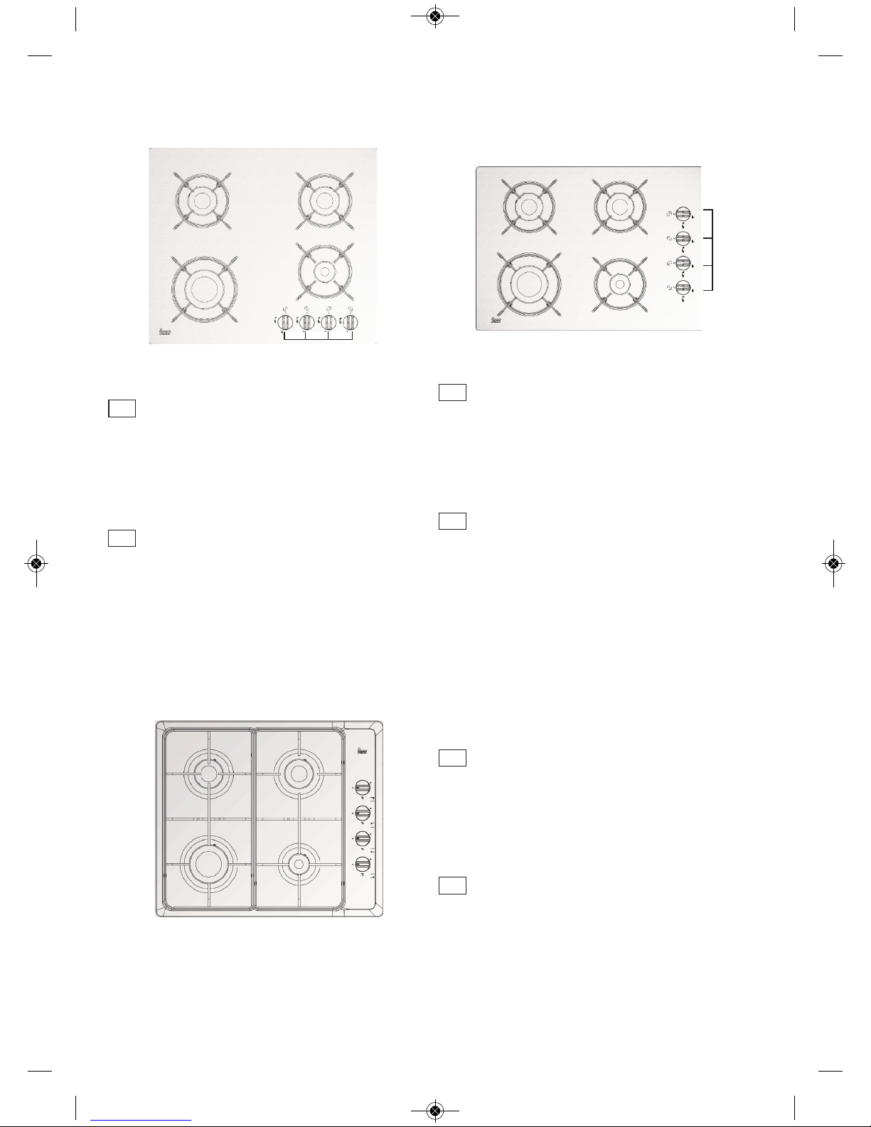
HF LUX 60 4G AL BUT
HF LUX 60 4G AL NAT
HF LUX 60 AI AL CI NAT
HF LUX 60 AI AL CI BUT
1 Semi-rapid burner 1,500 Kcal/h -1.75 kW.
2 Semi-rapid burner 1,500 Kcal/h -1.75 kW.
3 Rapid burner 2,850 Kcal/h -3.00 kW.
4 Auxiliary burner 860 Kcal/h - 1 kW.
5 Burner operating controls.
* All the burners have a grid.
* Maximum calorific power: 6,450 Kcal/h - 7.5 kW.
1 Quemador semi-rápido de 1.500 Kcal/h - 1.75 kW.
2 Quemador semi-rápido de 1.500 Kcal/h - 1.75 kW.
3 Quemador rápido de 2.580 Kcal/h - 3.00 kW.
4 Quemador auxiliar de 860 Kcal/h - 1 kW.
5 Mandos de accionamiento de los quemadores.
* Todos los quemadores llevan parrilla.
* Potencia calorífica máxima: 6.450 Kcal/h - 7.5 kW.
HF LUX 50 4G Al AL CI NAT
HF LUX 50 4G Al AL CI BUT
HF LUX 50 4G AL BUT
HF LUX 50 4G AL NAT
1 Semi-rapid burner 1,500 Kcal/h -1.75 kW.
2 Semi-rapid burner 1,500 Kcal/h -1.75 kW.
3 Rapid burner 2,850 Kcal/h -3.00 kW.
4 Auxiliary burner 860 Kcal/h - 1 kW.
5 Burner operating controls.
* All the burners have a grid.
* Maximum calorific power: 6,450 Kcal/h - 7.5 kW.
1 Quemador semi-rápido de 1.500 Kcal/h - 1.75 kW.
2 Quemador semi-rápido de 1.500 Kcal/h - 1.75 kW.
3 Quemador rápido de 2.580 Kcal/h - 3.00 kW.
4 Quemador auxiliar de 860 Kcal/h - 1 kW.
5 Mandos de accionamiento de los quemadores.
* Todos los quemadores llevan parrilla.
* Potencia calorífica máxima: 6.450 Kcal/h - 7.5 kW.
GB
GB
5
2
3
4
1
2
3
4
1
ES
ES
HLX 60 4G AL BUT
HLX 60 4G AL NAT
1 Semi-rapid burner 1,500 Kcal/h -1.75 kW.
2 Semi-rapid burner 1,500 Kcal/h -1.75 kW.
3 Rapid burner 2,850 Kcal/h -3.00 kW.
4 Auxiliary burner 860 Kcal/h - 1 kW.
5 Burner operating controls.
* All the burners have a grid.
* Maximum calorific power: 6,450 Kcal/h - 7.5 kW.
1 Quemador semi-rápido de 1.500 Kcal/h - 1.75 kW.
2 Quemador semi-rápido de 1.500 Kcal/h - 1.75 kW.
3 Quemador rápido de 2.580 Kcal/h - 3.00 kW.
4 Quemador auxiliar de 860 Kcal/h - 1 kW.
5 Mandos de accionamiento de los quemadores.
* Todos los quemadores llevan parrilla.
* Potencia calorífica máxima: 6.450 Kcal/h - 7.5 kW.
GB
ES
GB_61401134_en.qxd 05.03.2015 11:11 Page 3
5
2
Page 4
Guide to Using the Instructions Booklet
Dear customer,
We are delighted that you have put your
trust in us.
We are confident that the new hob that you
have purchased will fully satisfy your
needs.
This modern, functional and practical
model has been manufactured using topquality materials that have undergone
strict quality controls throughout the manufacturing process.
Before installing and using it, we would
ask that you read this Manual carefully and
follow the instructions closely, as this will
guarantee better results when using the
appliance.
Keep this Instruction Manual in a safe
place so that you can refer to it easily and
thus abide by the guarantee conditions.
In order to benefit from this Guarantee, it is
essential that you submit the purchase
receipt together with the Guarantee Certificate.
You should keep the Guarantee
Certificate or, where relevant, the
technical datasheet, together with the
Instruction Manual for the duration of
the useful life of the appliance. It has
important technical information about
the appliance.
Safety instructions
Before first use, you should carefully read
the installation and connection instructions.
These hob models may be installed in the
same kitchen furniture units as TEKA
brand ovens.
For your safety, installation should be
carried out by an authorised technician
and should comply with existing installation standards. Likewise, any internal work
on the hob should only be done by TEKA’s
technical staff, including the change of the
flexible supply cable of the appliance.
Safety warnings:
If the glass breaks or
cracks, the hob should immediately be disconnected from
electric current in order to
avoid the risk of electric
shock and all burners should
immediately be switched off.
Appliance surface shouldn't
be touched and used.
This appliance is not
designed to work with an
external timer (not built into
the appliance) or a separate
remote control system.
The device and its accessible parts may heat up
during operation. Avoid touching the heating elements.
Children younger than 8
years old must stay away
from the stovetop unless
they are permanently supervised.
This device may solely
be used by children 8 years
old or older, people with
impaired physical, sensory or
mental abilities, or those who
lack experience and knowledge, ONLY when supervised or
if they have been given adequate instruction on the use
GB_61401134_en.qxd 27.02.2015 14:52 Page 4
3
Page 5
of the device and understand
the dangers its use involves.
User cleaning and maintenance may not be done by
unsupervised children.
Children must not play
with the device.
Precaution. It is dangerous to cook with fat or oil
without being present, as
these may catch fire. Never
try to extinguish a fire with
water! in this event disconnect the device and cover the
flames with a lid, a plate or a
blanket.
Do not store any object
on the cooking areas of the
stovetop. Prevent a possible
fire hazard.
For safety reasons, we
advise that the instructions
provided by the gas supply
company are followed and
that the supply tap is turned
off when the hob is not in use.
If a gas smell is noted,
the gas intake to the hob
should be shut off and the
room ventilated. The gas installation and the hob should
also be checked by a specialised technician.
In the event of the burner
flames being accidentally
extinguished, turn off the burner control and do not
attempt to re-ignite the burner
for at least one minute.
This appliance must be
used exclusively for cooking,
never for other purposes
such as heating a room.
TEKA doesn't recommend the use of protective
covers for cooktops. The use
of inadequate protective
covers can cause accidents.
Steam cleaner should not
be used.
GB_61401134_en.qxd 27.02.2015 14:52 Page 5
4
Page 6

Important
INSTALLATION AND SETUP SHOULD
BE CARRIED OUT BY AN AUTHORISED
TECHNICIAN IN LINE WITH CURRENT
INSTALLATION STANDARDS.
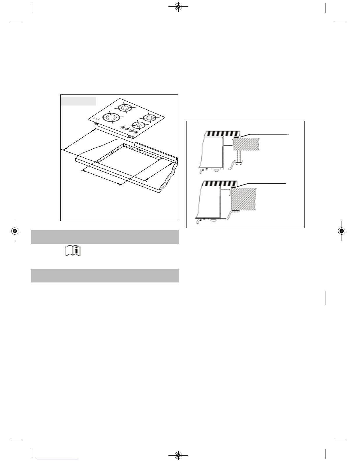
Positioning the hobs
Depending on the model to be installed, an
opening with the dimensions shown in
figure 2 will be cut into the unit’s worktop or
stove.
The system for fixing the hob is intended
for use with kitchen units with a thickness
of 20, 30 and 40 mm.
The minimum distance between the surface supporting the cooking pans and the
lower part of the kitchen unit or the hood
located above the hob should be 650 mm.
If the hood’s installation instructions
recommend that the gap is greater than
this, you should follow this advice.
The unit where the hob and oven will be
located will be suitably fixed.
Warnings:
When hobs are handled before
being installed, care should be taken in
case there is any protruding part or
sharp edge which could cause injury.
When installing units or appliances above the hob, the hob should be
protected by a board so that the glass
cannot be damaged by accidental
blows or heavy weights.
The glues used in manufacturing
the kitchen unit and in the adhesive on
the decorative laminate of the worktop
surface should be made to tolerate temperatures of up to 100ºC.
TEKA assumes no responsibility
for any malfunction or damage caused
by faulty installation.
Installation
GB_61401134_en.qxd 27.02.2015 14:52 Page 6
fig. 1
Minimum distances
to walls
Minimum ventilation
distances
5
Page 7
PLEASE REMEMBER THAT THE GUARANTEE DOES NOT COVER THE
GLASS IF IT SUFFERS A VIOLENT
BLOW OR IF IT IS USED IMPROPERLY.
Positioning the oven
See the corresponding manual.
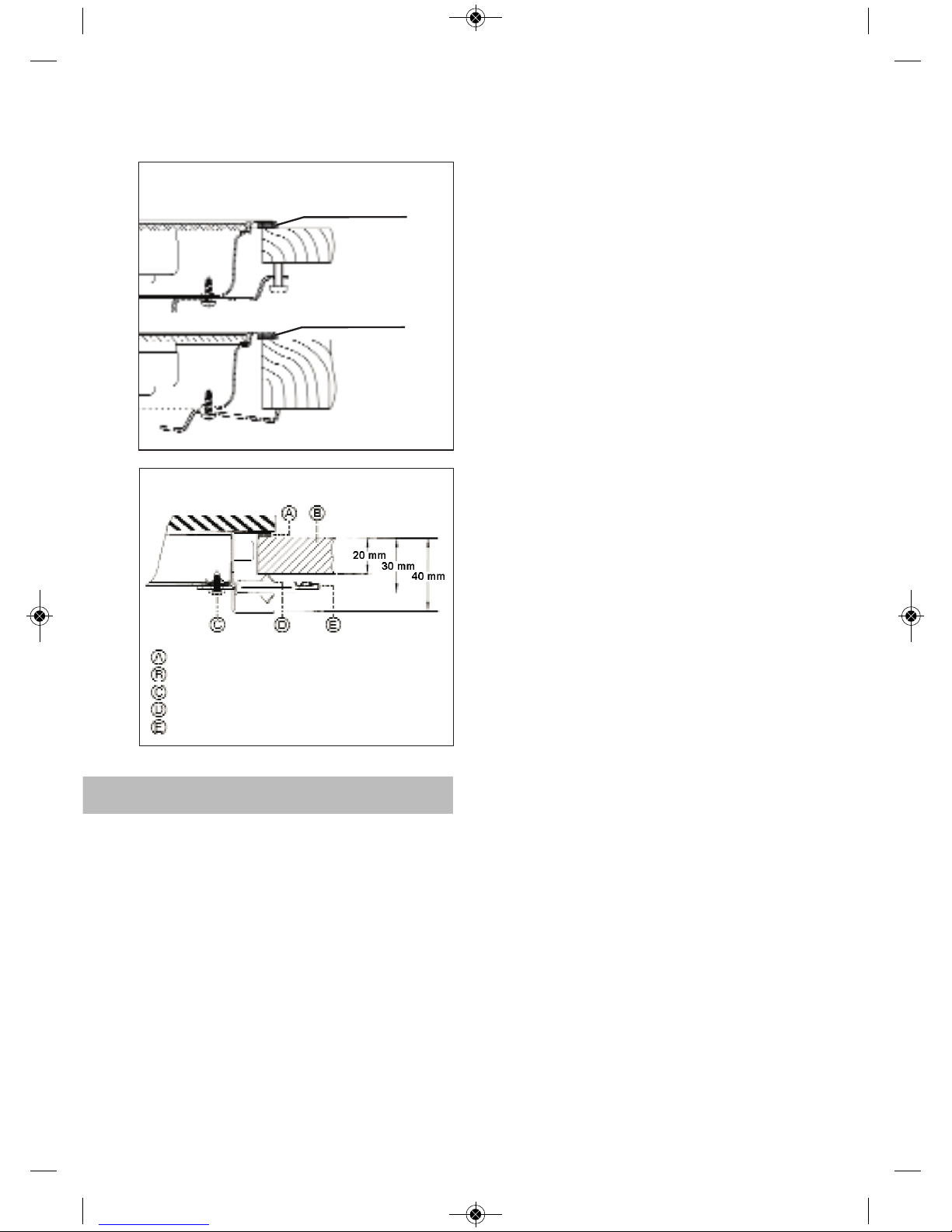
Anchoring the hob
When the gap has been properly sized, the
sealing washer should be put on the lower
face of the glass. Silicone should not be
applied between the glass and the unit
worktop because if it becomes necessary to remove the hob from its position,
the glass could break when trying to
detach it.
To secure the hob to the cabinet, four brackets should be fastened to the existing holes
on the bottom part of the casing (two in the
front and two in the back). There are two
possibilities of where the brackets may be
placed, just as is shown in figure 3.
Depending on the thickness of the cabinet, it
may be necessary to use the self tapping
screws that are provided as compliments for
securing; insert them in the circular holes of
the bracket. The thread of this hole will be
made when the screw is inserted inside of it.
The thread should be made before fastening the bracket to the hob.
Hob is mounted by inserting the quick nuts
into the holes where the screws go (see
fig. 5) and then attaching the appropriate
clip, depending on the worktop’s thickness
(20, 30 and 40 mm) and tightening the
screws until it is firmly fastened.
If an oven is being installed beneath the
hob, avoid the power cable coming into
contact with very hot components.
fig. 3
Sealing washer
Sealing washer
GB_61401134_en.qxd 27.02.2015 14:52 Page 7
fig. 2
575 max.
L
Fitting holes
The dimensions L and W are shown in the table
"Dimensions and characteristics" of the Technical
Information section.
W
6
Page 8
Connecting the Gas
Connecting the hob to the gas mains
should be done in compliance with the
current installation standards and/or regulations, and by a qualified technician (an
authorised installing engineer). The gas
connection for these hotplates should be
made with rigid piping, because the
appliance is a stationery one, where it is
destined for the EC market. The hob has a
threaded connection of 1/2’’ in diameter
(as per EN ISO 228-1 ) or 1/2’’ with a conical thread (as per EN 10226-1), depending
on the regulations in the destination
country.
For markets with an EN ISO 228-1 1/2’’
connection, a 10/12 mm copper pipe is
provided as an accessory for welding to
the gas intake pipe.
Ventilation slots should also be made at
the site in compliance with current norms.
Connecting the hob’s gas intake to the
mains should be done in compliance with
the basic gas installation standards for
residential premises.
TEKA assumes no responsibility for any
malfunction or damage that arises from an
incorrect or faulty installation.
In order that the hob is not damaged by
tightening the nut on the gas connection
pipe, a maximum torque of 300 cm * Kgf
should be applied.
When the gas connection has been made,
the installation should be checked to ensure that it is completely sealed. If the check
is done using air, care should be taken that
the test pressure is no more than 200
g/cm² Where air is not available, soapy
water should be applied to ensure that
there are no leaks in the connections. Tes-
ting should never be done using a
flame.
When the hob has been installed, check
that the burner minimums are properly
adjusted. To do this, light the burners and
check that they do not go out if you switch
quickly from the maximum to the minimum.
Whenever the gas connection nut is removed, its washer should be changed.
fig. 4
Sealing washer
Sealing washer
GB_61401134_en.qxd 27.02.2015 14:52 Page 8
fig. 5
Sealing washer
Worktop
Screw
Fixing clip
Rapid screw
7
Page 9
Connecting the Electricity
(Only hobs with automatic ignition or electric hotplates)
Before connecting the hob to the electric
mains, check that the voltage and frequency of the mains matches what is
shown on the hob’s rating plate, which is
located lower down, and on the guarantee
certificate or, where appropriate, the technical datasheet supplied, which should be
kept together with this manual.
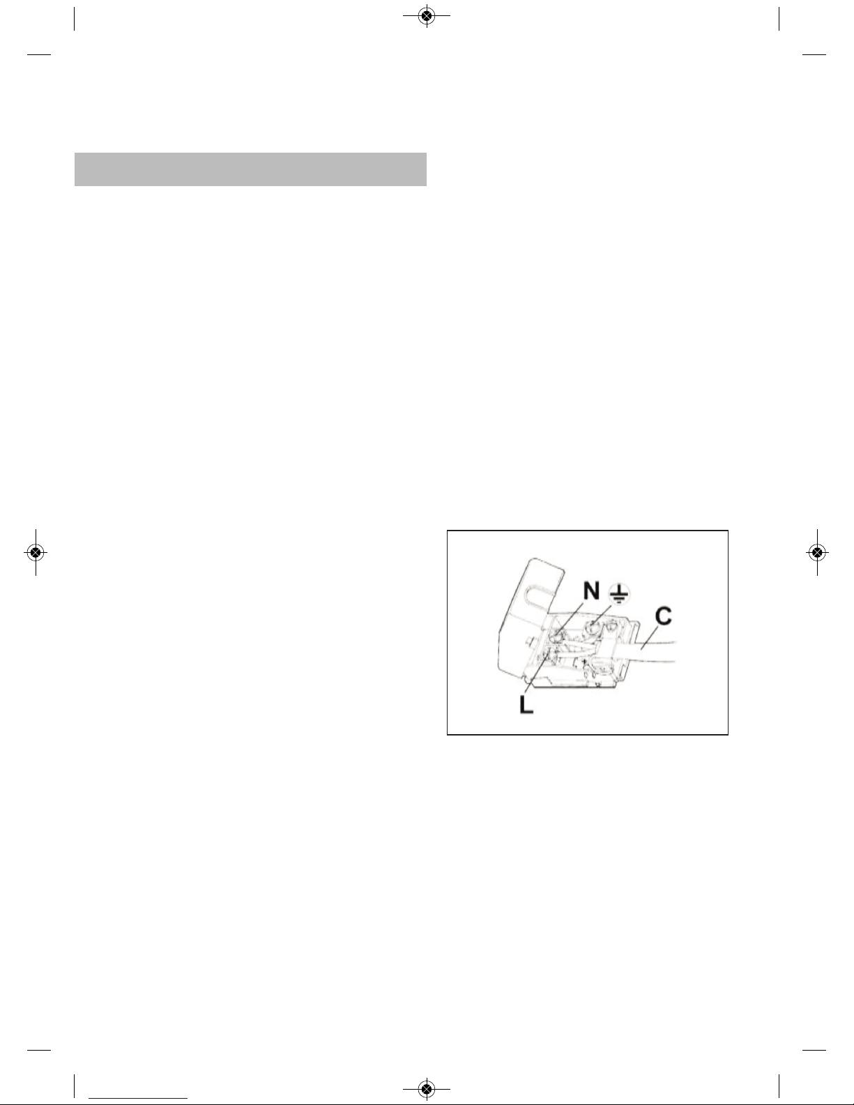
When the appliance is connected to the
electricity main by a socket:
* Fit a standard plug suited to the load indicated on the data label to the cable. Fit the
wires following figure 6, taking care of respecting the following correspondences:
Letter L (live) = brown wire;
Letter N (neutral) = blue wire;
Earth symbol = green - yellow wire.
* The power supply cable must be positioned so that no part of it is able to reach an
overtemperature of 65 K.
* Never use reductions, adapters of shunts
for connection since these could create
false contacts and lead to dangerous overheating.
The connection is made via an omnipolar
switch or plug where accessible, which is
suitable for the intensity to be tolerated
and which has a minimum gap of 3 mm
between its contacts, which will ensure
disconnection in case of emergency or
when cleaning the hob. It should also be
correctly earthed in line with current standards.
The connection should include correct
earthing, in compliance with current
norms.
If the flexible supply cable fitted to these
appliances ever needs to be changed, it
should be replaced by TEKA’s official service.
Need to allow the disconnection of the
network device after installation, via a
plug or switch accessible.
All our appliances are designed and
manufactured in compliance with European standards EN 60 335-1 and EN 60
335-2-6 plus the relative
amendments.
The appliance complies with the provisions of the following EEC Directives:
- 2004/108/EC regarding to
electromagnetic compatibility.
- 2006/95/EC regarding electrical safety.
fig. 6
GB_61401134_en.qxd 27.02.2015 14:52 Page 9
If the mains cord is damaged, should
be replaced by the manufacturer or its
after sales service.
8
Page 10
TR_61401134_en.qxd 13.10.2014 16:17 Page 11
9
Page 11
GB_61401134_en.qxd 27.02.2015 14:52 Page 10
10
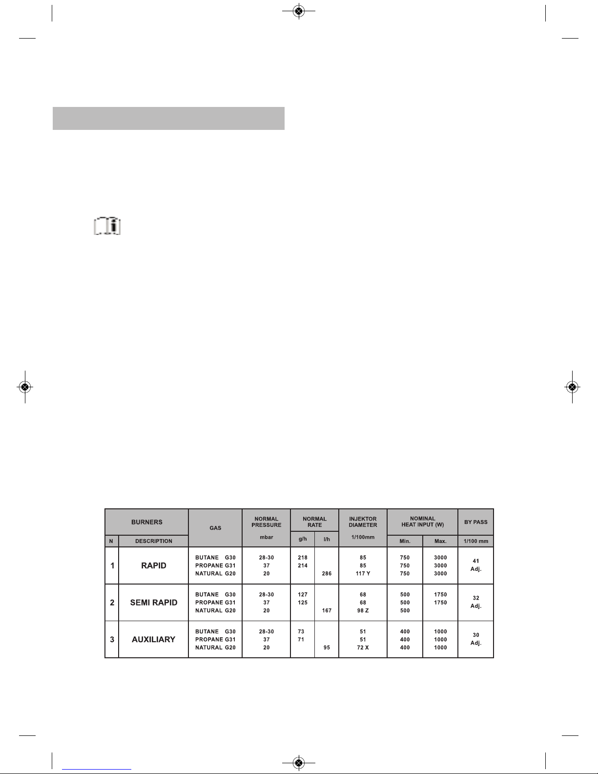
2 Us�ng a number 7 p�pe spanner, remove
Gas convers�on
ImportantY
Any alterat�on that �s to be made to the
appl�ance to convert �t to a d�fferent
type of gas should only be carr�ed out
by a qual�f�ed techn�c�an.
Informat�on for Techn�cal Ass�s-
tance: whenever the type of gas or the
appl�ance’s pressure �s changed, the new
regulat�on plate should be placed on top of
the old one so that the new features can
be seen after the change.
The tasks �nvolved �n convers�on are:
the �njectors and replace them w�th the
new ones. Take care to press the �njector
down f�rmly so that there �s no leakage.
3 Replace the gr�d and burners that were
prev�ously removed.
When the �njectors have been changed,
th�s �s how to adjust the m�n�mums:
1 Turn the burners on to the�r m�n�mum.
2 Pull the taps’ controls f�rmly upwards to
remove them.
3 Use a sl�m, grooved screwdr�ver to turn
the screw located to the r�ght or �n the
centre of the gas tap’s shaft (the flame
�ncreases when you turn to the left and
decreases when you turn to the r�ght).
4 When properly adjusted, check that the
flame does not go out when you turn the
knob qu�ckly from max�mum to m�n�mum.
The �njectors requ�red for each gas type
are shown �n table 1.
To replace the �njectors, follow these �nstruct�ons:
1 Remove the gr�ds and upper parts of the
burner so that the �njector can be seen.
TEKA INDUSTRIAL, S.A. assumes no
respons�b�l�ty for any hob malfunct�on �f the
gas convers�on or the adjustment of the
burners’ m�n�mums has not been carr�ed
out by TEKA’s off�c�al personnel.
Table 1
°
* Replace the �njectors.
* Adjust the taps’ m�n�mums.
Page 12
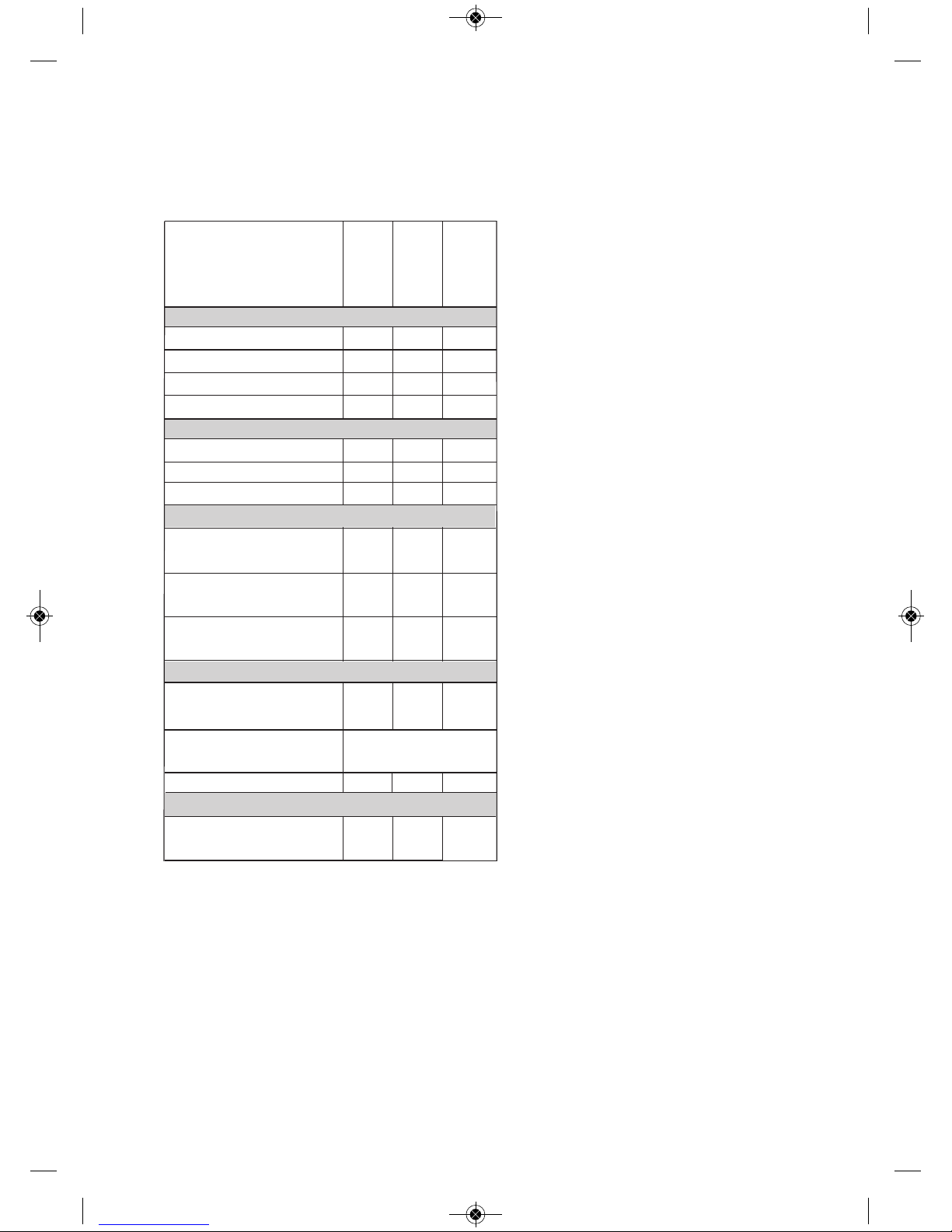
Technical Information
Dimensions and powers
Models
SEE RATING PLATE
** For voltages other than 230 V please consult the appliance’s rating plate.
580
500
110
8
560
480
70
2
1
7,5
50/60
0,6
HF LUX
50 4G
Al AL CI
600
435
110
8
575*
405
70
1
2
1
50/60
0,6
* With granite hobs, the measurement may be 580 mm.
HF LUX
60 4G AL
1
Dimensions in mm
Length
Width
Height
Glass thickness
Dimensions of the space in the unit mm
Length (L)
Width (W)
Depth
Power per burner and hotplate
Rapid gas
burner 3 kW.
Semi-rapid gas
burner 1.75 kW.
Auxiliary gas burner
1 kW.
Electrics
Nominal power
(W) for 230 V**
Supply
voltage V.
Frequency Hz.
Gas
Nominal Calorific
Consumption kW.
HLX 60
4G AL
580
500
90
553
473
65
1
2
1
7,5
50/60
0,6
7,5
GB_61401134_en.qxd 27.02.2015 14:52 Page 11
HLX 60
4G AI AL
HF LUX
50 4G AL
HF LUX
60 AI AL
CI
11
Page 13
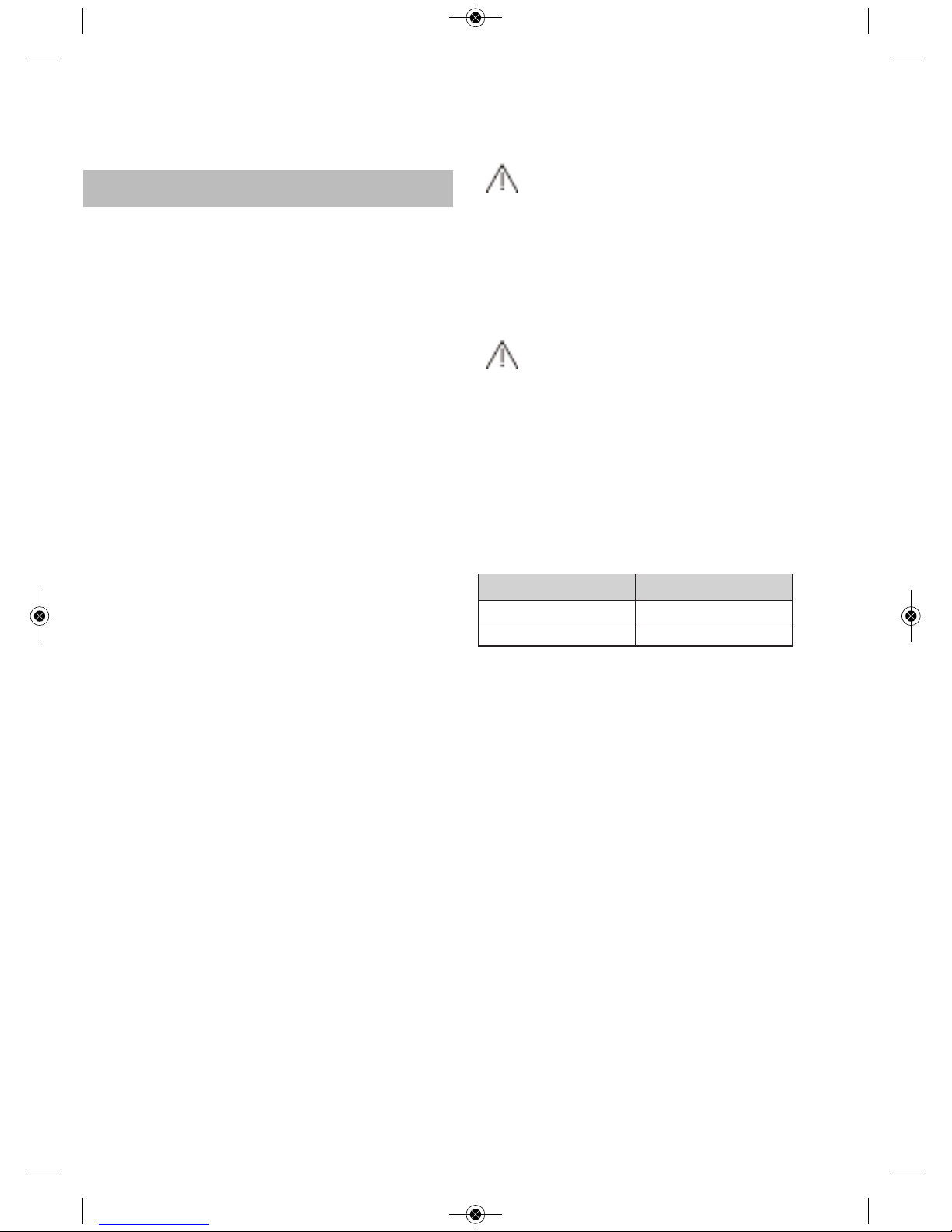
Technical data
COMMON FEATURES FOR ALL MODELS
WITH ELECTRIC HOTPLATES AND AUTOMATIC IGNITION
The supply voltage and frequency will be
as shown on the rating plate.
If an electric hotplate gets cracked, the
hob should be disconnected from the electricity current.
COMMON FEATURES FOR ALL
MODELS WITH GAS BURNERS
Warnings:
a) Before installation, make sure that the
local supply conditions (the gas type and
pressure) are compatible with the appliance’s setup.
b) The setup conditions for this appliance
are written on the label (or the rating
plate).
c) This appliance should not be connected
to a device for removing combustion
products. It should be installed and connected in compliance with the current installation standards. Special attention
should be paid to the regulations applying
to ventilation.
A gas cooking appliance produces heat and moisture at the site where
it is installed. The kitchen should be
provided with suitable ventilation: natural ventilation sources should be kept
clear, a window opened, or an effective
mechanical ventilation system device,
such as a hood, installed.
The intense and prolonged use
of the appliance may call for complementary ventilation, such as opening a
window, or more efficient ventilation
such as increasing the power of the
mechanical ventilation if this exists.
Class 3 Hob.
Table 2
GB_61401134_en.qxd 27.02.2015 14:52 Page 12
País
Spain
Portugal
II2H3+
II2H3+
Country
Category
12
Page 14

Elements of a burner
Whenever you reassemble a burner,
check that all the components are properly in place, as a part that is wrongly
positioned can lead to overheating and
damage the glass.
Igniting the burners
* Make sure that the knobs are in their
correct position.
* Turn on the gas at the mains or turn the
gas cylinder’s tap.
* Press down the burner control.
* Keeping the burner control pressed
down, turn it all the way till the gas igni-
tes. Keep it pressed down for between 2
and 5 seconds so that the safety ther-
mocouple can take effect.
* Set the control to the position required.
The ignition (ceramic and electrode)
should be cleaned regularly and carefully in order to avoid ignition problems.
Check, too, that the grooves in the burners have not become obstructed.
Use and Maintenance
fig. 7
Grid
Diffusing cover
Diffusing crown
Injector
Injector holder
fig. 8
‘Burner in operation’ indicator
Knob position when not in use
Maximum gas position
Minimum gas position
Off position
Star (On position)
GB_61401134_en.qxd 27.02.2015 14:52 Page 13
13
Page 15

The device shall not be operated
for more than 15 seconds. If after 15
seconds the burner has not lit, stop the
device and open the compartment door
and/or wait at least 1 minute before
attemting a futher ignition of the burner.
Anti-accidental turn system
on gas controls
On models without the safety system (without the gas cut-off device), the
gas taps are equipped with a mechanical
system that prevents the controls from
being freely turned from the off position to
the on position (and, therefore, prevents
any accidental escape of gas from the burners) if the control has not previously
been pressed down.
If at any time while using the hob
you notice that a control can be turned
from the off position without it needing
to be pressed down beforehand (for
example: due to dirt which may have
got into the gas taps and built up there)
you should, for your own safety, get
quickly in touch with technical assistance in order to resolve this fault.
Safety system
components
On hobs with the safety feature (those
models which have the letters AL), the gas
cut-off device is made up of these elements:
* The safety tap
* The safety thermocouple, next to the burner
* The thermocouple-tap connection
The thermocouple sends an electric signal
to the tap which identifies whether the burner has a flame. During ignition, the tap
should be held down for at least 5
seconds, until the thermocouple has heated up and can send a satisfactory electric
signal to the tap. Should the burner go out,
the absence of a flame is detected by the
thermocouple, which makes the safety tap
cut off the flow of gas.
‘Burner in operation’ indicator
Control indicator
Off position
Maximum gas position
Minimum gas position
Burner on position
fig. 9
Safety thermocouple
Thermocouple-tap connection
Spark generation connection
Ignition spark plug
Ceramic head
Electrode
Safety tap
fig. 10
GB_61401134_en.qxd 27.02.2015 14:52 Page 14
14
Page 16

Maintenance of the glass
* When using a roasting dish, clay pots or
any utensil that reflects heat downwards, it is essential that the grid accessory is used, for otherwise the high temperature that is reflected downwards
could damage the glass or the burners.
* The grid accessory can be used when
cooking with pans that have a small
base or when a very low heat is required, for slow cooking or to keep food
warm. When it is used, the burner is less
efficient.
* If you notice that the glass is broken or
cracked, set all the hotplate controls to
“zero” (turned off) turn off the gas tap
and disconnect the electricity. Then contact TEKA’s Technical Service.
* Do not use the glass surface as a stora-
ge area.
* Do not put aluminium foil, tin foil or plas-
tics on the surface of the glass.
* With five burner models, very large pans
should be placed on the central burner
so that they do not reflect heat onto the
kitchen unit worktop. With four burner
models, use the grid accessory with this
sort of pan.
Suggestions for using the
burners effectively
* Rapid burners should not be used with
pans that have a small diameter, because part of the flame will spread away
from the pan, thus reducing performance significantly. (See fig. 13.
* The burners should not be operated wit-
hout there being a pan on them, or gas
will be wasted and the grid will heat up
excessively.
* When the burners are in operation they
ought not to be exposed to strong
draughts, because as well as losing
calorific power, there is the danger of the
flame going out, which would lead to gas
escaping and could cause an accident.
This point is particularly important when
the burners are operating at their minimum power.
* If the burner makes the pans smoky, or
fig. 12
Grid accessory
fig. 11
Roasting dish, clay pots or utensils that
reflect heat downwards
fig. 13
Right
Wrong
GB_61401134_en.qxd 27.02.2015 14:52 Page 15
Burners Power ratings Pan Ø in cm
Wok 3300 24 ÷ 26
Rapid 3000 20 ÷ 22
Semirapid 1750 16 ÷ 18
Auxiliary 1000 10 ÷ 14
15
Page 17

if the tip of the flame is yellow, the burner should be cleaned. If this anomaly
persists, contact the Technical Assistance Service in order that the main air inlet
can be adjusted or the gas supply pipe
cleaned.
* Cast iron plates should not be used on
the grid, because they reflect too much
heat onto the cooker’s hotplate.
* Pans placed on the burners should not
jut out beyond the edge of the hotplate,
so that the reflected flame does not
damage worktops with a plastic surface.
* Use pans with a flat base.
Maintenance of the burners
Whenever the gas taps are removed, you
should change the washer that is between
the taps and the supply pipe.
The burners are working properly when their
flame is stable and a greeny-blue colour. If
the tips of the flames are yellow, the burners
need to be cleaned; if the problem persists,
contact the Technical Service.
In order to guarantee the gas installation is
properly sealed and the burners are working properly, the hob needs to be inspected by specialised Technical Service personnel at least once every year.
Note:
Any alteration or adjustment needed by
the appliance should be made by authorised technical personnel.
Environmental
considerations
The symbol on the product or on
its packaging indicates that this product may not be treated as household
waste. Instead it shall be handed over
to the applicable collection point for the
recycling of electrical and electronic
equipment. By ensuring this product is
disposed of correctly, you will help prevent potential negative consequences
for the environment and human health,
which could otherwise be caused by
inappropriate waste handling of this
product, please contact your local city
office, your household waste disposal
service or the shop where you purchased the product.
Packaging materials are organic and
fully recyclable. Plastic components
are identified by marking >PE<, >LD<,
>EPS<, etc. Throw out packaging materials, such as household waste, in the
container of your municipality..
GB_61401134_en.qxd 27.02.2015 14:52 Page 16
16
Page 18

Do not use small pans on large burners, or the flame
will spread.
Match pans to burners to make best use of the heat.
Reminder
GB_61401134_en.qxd 27.02.2015 14:52 Page 17
Do not place the pan away from the centre of the
burner.
Place the pan properly, in the middle of the burner.
The pans placed on the burners should not go out of
the limits of the apliance, for not damaging the work
surface
Do not use utensils that reflect a lot of heat downwards directly onto the grid.
When using roasting dishes, clay pots or pans that
reflect heat downwards, use the grid accessory.
Do not use sharp objects on the cooker.
When the grids have been used they should be
cle-aned when they have cooled down.
Do not use heavy weights or hit the cooker with
heavy objects.
Handle pans with care on and around the cooker.
Do not place the pans directly on the burner.
Place the pans on the grid.
17
Page 19

For best care of the glass, it should be cleaned when it is cold, with suitable products. It should be cleaned after each use,
so that cleaning is easier and there is no
build-up of dirt from repeated use.
When cleaning the glass, the degree of
soiling should be taken into consideration, and the following guidelines followed:
* When soiling is light and not stuck fast,
a damp cloth and a soft detergent can
be used.
* Staining or grease should be cleaned
with cleaning products that are suitable
for glass.
* If any objects or plastic utensils or sugar
melts onto the glass, it should be removed
immediately, while hot, using a scraper.
* Never use aggressive or abrasive clea-
ning products that could cause scratches, such as oven cleaning aerosols,
rust removers or sponges or scourers
with a hard surface.
* Do not slide pans over the glass, as they
can cause scratches.
* Ensure that the liquid does not evapora-
te from pans, because the heat building
up at the base could damage the burner
or the glass.
* The glass will tolerate light bangs from
big pans that do not have sharp edges.
Be careful with impacts from small,
sharp instruments. Do not bang pans
against the edge of the glass, since this
can damage the glass irreparably.
* Do not spill cold liquids on the glass or
burners when they are hot.
* Do not stand or lean on the glass, as it
might break and cause damage.
To clean and care for other components, follow these guidelines:
* The grids should be cleaned with a non-
abrasive scourer when they have cooled
down.
* The burners - the grooves in particular -
should be cleaned at regular intervals;
they should be put into warm, soapy
water and cleaned with a scourer or a
stiff brush.
* Do not clean the enamel burners’ diffu-
sing covers while they are still hot. Abrasive products can cause damage: vinegar, coffee, milk, salty water and tomato
juice that have lengthy contact with the
enamel surfaces.
* The stainless steel should be washed in
soapy water using a soft cloth. If the
metal is yellowish after this, we suggest
the use of lemon, vinegar, dilute ammonia or a cleaning product that contains
dilute ammonia. You can keep the metal
shiny by gently rubbing with a polish that
can be easily obtained from outlets
selling cleaning products.
* The control panel should be cleaned
with soapy water and a soft cloth.
* When cleaning the appliance with the
burners removed, care should be taken
not to allow liquid or other objects to get
into the bend of the injector holder.
* When cleaning, do not use products that
can harm aluminium, such as soda, oil,
etc.
* The ignition unit (ceramic and electrode)
must be periodically cleaned with care in
order to prevent ignition problems. A
check should also be made that the burner slots are not obstructed.
Cleaning and care
GB_61401134_en.qxd 27.02.2015 14:52 Page 18
18
Page 20

If something doesn’t work
Fault Possible cause Possible solution
There is no spark when the
automatic ignition control is pressed
There is no current
at the plug
Check/repair the
electricity at the mains
The gas burners are making the pans dirty
The burner openings
are dirty
Clean the burners’
openings
The injector or
injector holder is dirty
Clean the injector holder
and injector without using
anything which could
damage or alter the
diameter of the gas outlet
opening
Before calling the Technical Service, please
make the following checks:
There is a spark but the burner is not igniting
The spark plug and the part
of the burner where the
spark should be is soiled or
greasy
Clean the end of the
spark plug and the
burner
Do not light the gas burners
Gas is not coming through
to the hob
Check that the gas
cylinder tap is properly
open
If it is piped gas, open
the gas tap
The burner ignites but, when you stop holding down the knob
that activates the safety feature, it goes out again
The flame is not appearing
in the area heated by the
thermocouple
Clean the burner’s
openings
GB_61401134_en.qxd 27.02.2015 14:52 Page 19
Direction of the manufacturer : SİMECO Isı Ekipmanları ve Kalıp San. A.Ş.
Ege Serbest Bölgesi Akçay Cad. No:144/1 Gaziemir – İzmir
19
Page 21

GB_61401134_en.qxd 27.02.2015 14:52 Page 19
Model description (incl. version)
HF LUX 60 4G AL
HF LUX 60 Al AL CI
HF LUX 50 4G AL HF
LUX 50 4G Al AL CI
Type of hob Gas Hob
Number of cooking zones and/or areas
4
Energy efficiency per gas burner
(EE gas burner)
Front left 58,7
Rear Left 56,8
Front Center
Rear Center
Front Right
Rear Right
56,8
Energy efficiency for the gas hob
(EE gas hob)
57,4
PRODUCT INFORMATION
Model description (incl. version)
HLX 60 4G AL
HLX 60 4G Al AL
Type of hob Gas Hob
Number of cooking zones and/or areas
4
Energy efficiency per gas burner
(EE gas burner)
Front left
54,2
Rear Left 55,5
Front Center
Rear Center
Front Right
Rear Right
55,5
Energy efficiency for the gas hob
(EE gas hob)
55,1
PRODUCT INFORMATION
20
Page 22

Guía de Uso del Libro de Instrucciones
Estimado cliente,
Agradecemos sinceramente su confianza.
Estamos seguros de que la adquisición de
nuestra encimera de cocción va a satisfacer plenamente sus necesidades.
Este moderno modelo, funcional y práctico, está fabricado con materiales de primerísima calidad, los cuales han sido
sometidos a un estricto control de calidad
durante todo el proceso de fabricación.
Antes de su instalación o uso, le rogamos
lea atentamente este Manual y siga fielmente sus instrucciones, para garantizar
un mejor resultado en la utilización del
aparato.
Guarde este Manual de Instrucciones en un
lugar seguro para poder consultarlo y así
cumplir con los requisitos de la garantía.
Para poder beneficiarse de esta Garantía,
es imprescindible presentar la factura de
compra del aparato junto con el certificado
de garantía.
Conserve el Certificado de
Garantía o, en su caso, la hoja de datos
técnicos junto al Manual de instrucciones durante la vida útil del aparato.
Contiene datos técnicos importantes
del mismo.
Instrucciones de Seguridad
Antes de la primera puesta en servicio
observar atentamente las instrucciones de
instalación y conexión.
Estos modelos de encimeras de cocción
pueden instalarse en los mismos módulos
del amueblamiento que los hornos de la
marca TEKA.
Por su seguridad, la instalación deberá
ser realizada por personal autorizado y de
acuerdo a las normas de instalación en
vigor. Asimismo, cualquier manipulación
interna de la encimera deberá ser realizada únicamente por personal del servicio
técnico de TEKA, incluida la sustitución
de cable de red.
Atención:
En caso de rotura o fisura del vidrio, la encimera
deberá desconectarse inmediatamente de la toma de
corriente para evitar la posibilidad de sufrir un choque
eléctrico, todos los quemadores deben ser inmediatamente desconectados. La
superficie del aparato no
debe ser tocada ni usada.
El aparato y sus partes
accesibles pueden calentarse
durante su funcionamiento.
Evite tocar los elementos
calefactores. Los niños
menores de 8 años deben
mantenerse alejados de la
encimera, a menos que se
encuentren bajo supervisión
permanente.
Este aparato puede ser
utilizado por niños con ocho
o más años de edad, personas con reducidas capacidades físicas, sensoriales o
mentales, o falta de experiencia y conocimientos, SÓLO
bajo supervisión, o si se les
ha dado la instrucción apropiada acerca del uso del aparato y comprenden los peligros que su uso implica. La
limpieza y mantenimiento a
cargo del usuario no han de
ES_Maquetación 1 05.03.2015 11:33 Page 3
21
Page 23

ser realizadas por niños sin
supervisión.
Los niños no deben jugar
con el aparato.
Precaución. Es peligroso
cocinar con grasas o aceites
sin estar presente, ya que
pueden producir fuego.
¡Nunca trate de extinguir un
fuego con agua! en ese caso
desconecte el aparato y
cubra las llamas con una
tapa, un plato o una manta.
Este aparato debe ser
utilizado exclusivamente
para cocinar, nunca para
otros propósitos tales como
calentar una habitación.
Cuando los quemadores
están funcionando o después
de haber funcionado, en la
placa de la encimera hay
zonas calientes que pueden
producir quemaduras.
Mantener alejados a los
niños.
Por razones de seguridad, recomendamos sigan las
instrucciones de la compañía
suministradora de gas
cerran-do la llave de
suministro cuando no se
utilice la enci-mera.
Si se aprecia olor a gas
debe cerrarse la llave de paso
de gas a la encimera y ventilar la habitación. Además
debe ser comprobada la instalación de gas y la encimera
por un técnico especializado.
El dispositivo de encendido automático no se debe
accionar durante más de 15
segundos. Si durante este
tiempo el quemador no se
enciende, deje de actuar
sobre él y abra la puerta de la
estancia y/o espere al menos
un minuto antes de intentar
encender el quemador de
nuevo.
En el caso de una extinción accidental de las llamas
del quemador, cierre el
mando de accionamiento del
mismo y no intente encender-lo
de nuevo durante al menos un
minuto.
El uso de un aparato de
cocción a gas produce calor y
humedad en el local donde está
instalado. Debe asegu-rarse
una buena ventilación de la
cocina: manteniendo abiertos
los orificios de venti-lación
natural, o abriendo una
ventana, o instalando un eficaz
dispositivo de ventila-ción
mecánica (campana de
ventilación mecánica).
La utilización intensa y
prolongada del aparato puede
necesitar una ventila-ción
complementaria, por ejemplo,
abriendo una venta-na, o una
ventilación más efi-caz, por
ejemplo, aumentan-do la
potencia de la ventila-ción
mecánica, si existe.
No deje cualquier objeto
en las áreas de cocinar. Evite
cualquier peligro de incendio.
PRECAUCIÓN: TEKA no
recomienda el uso de protectores de encimera. El uso de
protectores inadeacuados
puede causar accidentes.
No se deben usar limpiadores a vapor
ES_Maquetación 1 05.03.2015 11:33 Page 4
22
Page 24

Importante
LA INSTALACIÓN Y AJUSTE DEBEN
SER EFECTUADOS POR UN TÉCNICO
AUTORIZADO DE ACUERDO A LAS
NORMAS DE INSTALACIÓN EN VIGOR.
Emplazamiento de las
encimeras de cocción
Dependiendo del modelo a instalar se practicará en la encimera del mueble o fogón
una abertura con las dimensiones especificadas la figura 2.
El sistema de sujeción de la encimera está
previsto para espesores del mueble de 20,
30 y 40 mm.
La distancia entre la superficie de soporte
de los recipientes de cocción y la parte
inferior del mueble o campana colocado
sobre la encimera debe ser, como mínimo,
de 650 mm. Si las instrucciones de instalación de la campana indican una distancia
superior, esta debe ser tenida en cuenta.
El mueble donde se colocará la encimera
con horno estará convenientemente fijado.
Advertencias:
Cuando se manipulan las encimeras antes de instalarlas debe hacerse con precaución por si pudiera haber
alguna zona o esquina que produjera
cortes.
Durante la instalación de muebles o aparatos sobre la encimera, esta
se debe proteger mediante una tabla,
para evitar la rotura del vidrio a causa
de golpes o un peso excesivo.
En caso de rotura o fisura del
vidrio la encimera deberá desconectar-
se inmediatamente de la toma de
corriente para evitar la posibilidad de
sufrir un choque eléctrico.
Las colas utilizadas en la fabricación del mueble, o en el pegado de las
lamas decorativas y de las que forman
parte de las superficies de la mesa de
trabajo, deben estar preparadas para
soportar temperaturas hasta 100º C.
TEKA no se hace responsable de
las averías o daños que puedan ser
causados por una mala instalación.
Instalación
ES_Maquetación 1 05.03.2015 11:33 Page 6
fig. 1
Minimum distances
to walls
Minimum ventilation
distances
23
Page 25

TENGA EN CUENTA QUE EL VIDRIO NO
TIENE GARANTIA SI ES GOLPEADO O
MANIPULADO INDEBIDAMENTE.
Emplazamiento del horno
Véase el manual correspondiente.
Anclaje de la encimera
de cocción
Una vez dimensionado el emplazamiento
se procede a pegar la junta de estanqueidad sobre la cara inferior del vidrio.
No aplique silicona directamente
entre el vidrio y la encimera del mueble
ya que, en caso de necesitar retirar la
cocina de su emplazamiento, pueden
producirse roturas en el vidrio al intentar
despegarlo.
Colocación de las grapas:
Para sujetar la encimera de cocción al mueble, se suministran cuatro grapas que
deben ser fijadas a los orificios existentes
en la parte inferior de la carcasa (dos anteriores y otras dos posteriores). Existen dos
alternativas para el posicionamiento de las
grapas, tal y como se muestra en las figuras
3 y 4.
Dependiendo del espesor del mueble es
posible que necesite utilizar los tornillos
autorroscantes que se suministran como
complemento de sujeción, insertándolos
en el orificio circular de la grapa. La rosca
de este orificio se irá creando al insertar el
tornillo en él. Este roscado se debe realizar antes de fijar la grapa a la encimera.
En el montaje se realiza introduciendo las
tuercas rápidas en los alojamientos donde
van los tornillos, (ver fig. 5), acople des-
fig. 2
Abertura de
encastre
Las dimensiones L y A se encuentran en la tabla
"Dimensiones y características" del apartado
Información Técnica.
575 max.
A
L
fig. 3
Junta de estanqueidad
Junta de estanqueidad
fig. 4
Junta de estanqueidad
Junta de estanqueidad
ES_Maquetación 1 05.03.2015 11:33 Page 7
24
Page 26

pués la grapa que corresponda según la
medida de altura de la encimera del mueble (20, 30 y 40 mm.) y apriete los tornillos
hasta quedar bien sujeta.
Si se instala un horno debajo de la encimera de cocción, evitar que el cable de
toma de corriente quede en contacto con
partes excesivamente calientes.
Conexión del Gas
La conexión de la toma de gas de la encimera de cocción a la red, debe realizarse
siguiendo las normas o reglamentos de
instalación en vigor y por personal técnico
cualificado (un instalador autorizado). La
conexión del gas de estas placas de cocinar debe realizarse con tubería rígida,
pues se trata de un aparato inmovilizado,
en el caso de encimeras destinadas a la
CE. La encimera de cocción viene preparada con una conexión roscada según EN
ISO 228-1 de 1/2'' de diámetro o EN
10226-1 de 1/2'' con rosca cónica, dependiendo de la reglamentación del país de
destino.
Para los mercados con conexión EN ISO
228-1 de 1/2'' se suministra como accesorio un tubo de cobre de diámetro 10/12
mm. en el cual se puede soldar el tubo de
toma de gas.
Además deben realizarse las rejillas de
ventilación en el local según indica la normativa vigente.
La conexión de la toma de gas de la placa
de cocinar a la red, debe realizarse
siguiendo las normas básicas de instalación de gas en edificios habitados.
TEKA no se responsabiliza de las averías
o daños producidos por una mala o defectuosa instalación.
Para no dañar la encimera al apretar la
tuerca del tubo de la conexión de gas,
debe utilizarse un par de apriete máximo
de 300 cm * Kgf.
Una vez realizada la conexión del gas
debe comprobarse la estanqueidad de la
instalación. Si la comprobación se hace
con aire, ha de tenerse en cuenta que la
presión de prueba no sea superior a 200
gr./cm². En caso de no disponer de aire,
aplicar agua jabonosa para comprobar la
ausencia de fugas en las uniones. Es
totalmente desaconsejable hacer la
comprobación con una llama.
Una vez instalada la encimera comprobar
que los mínimos de los quemadores están
bien regulados. Para ello encender los
quemadores y comprobar que no se apagan al pasar bruscamente del máximo al
mínimo.
Cada vez que se desmonta la tuerca de
conexión de gas debe cambiarse la junta
que lleva la misma.
Conexión Eléctrica
(Solamente cocinas con autoencendido o
placas eléctricas)
Antes de conectar la encimera de cocción
fig. 5
Junta de estanqueidad
Mueble de encimera
Tornillo
Grapa de fijación
Tuerca rápida
ES_Maquetación 1 05.03.2015 11:33 Page 8
25
Page 27

a la red eléctrica, compruebe que la tensión (voltaje) y la frecuencia de aquella
corresponden con las indicadas en la
placa de características de la encimera, la
cual está situada en su parte inferior y en
la hoja de garantía o, en su caso, la hoja
de datos técnicos adjunta que debe de
conservar junto a este manual.
Cuando el aparato se conecta a la corriente eléctrica mediante un enchufe:
Aplique un enchufe normalizado adecuado para la carga indicada en la etiqueta de
identificación. Conecte los cables según la
figura 6, prestando atención de respetar
las siguientes correspondencias:
Letra L (fase) = cable de color marrón;
Letra N (neutro) = cable de color azul;
Símbolo tierra = cable de color verde-amarillo
El cable de alimentación debe colocarse
de manera que no alcance en ningún
punto una temperatura de 65K.
Nunca utilice reducciones, adaptadores o
derivadores para efectuar la conexión
puesto para efectuar la conexión puesto
que podrían provocar falsos contactos y
peligrosos sobrecalentamientos.
La conexión se realizará a través de un
interruptor de corte omnipolar o clavija
siempre que sea accesible, adecuado a la
intensidad a soportar y con una apertura
mínima entre contactos de 3 mm., que
asegure la desconexión para casos de
emergencia o limpieza de la encimera. La
conexión debe realizarse con una correcta
toma de tierra, siguiendo la normativa
vigente.
La conexión debe realizarse con una
correcta toma de tierra, en cumplimiento
con la normativa vigente
Cualquier manipulación o reparación del
aparato, incluida la sustitución del cable
flexible de alimentación, deberá ser realizada por el servicio técnico oficial de
TEKA.
La toma debe quedar accesible después
de efectuar el encastre, a través de enchufe o interruptor accesibles.
ADVERTENCIA.
Todos nuestros aparatos han sido diseñados y fabricados según las normas europeas EN 60 335-1, EN 60 335-2-6 y EN 60
335-2-102 y sus relativas enmiendas.
El aparato cumple las disposiciones de las
Directivas Europeas:
CEE 2004/108/CE relativa a la compatibilidad electromagnética
CEE 2006/95 relativa a la seguridad eléctrica.
ES_Maquetación 1 05.03.2015 11:33 Page 9
fig. 6
Si el cable de alimentación está dañado,
debe ser sustituido por el fabricante o
su servicio posventa
26
Page 28

TR_61401134_en.qxd 13.10.2014 16:17 Page 11
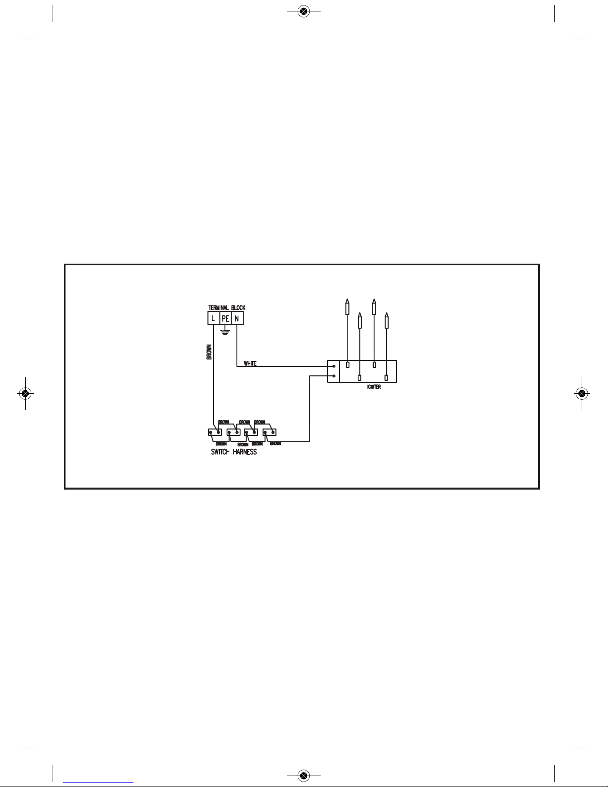
Caja de Conexsiones
Marrón
Blanco
Generador de chispa
27
Page 29

La Transformación del gas
¡Importante!
Cualquier modificación del aparato para
su adaptación a un gas diferente del
que viene preparado, debe ser realizada
únicamente por un técnico cualificado.
Información para el Servicio
Técnico: en caso de conversión del tipo
de gas o presión en el aparato, deberá
colocarse la nueva etiqueta de regulación
sobre la existente, con el fin de identificar
las nuevas características después del
cambio.
Las intervenciones necesarias para la
transformación son:
* La sustitución de los inyectores.
* La regulación de mínimos de los grifos.
Los inyectores necesarios para cada tipo
de gas son los indicados en la tabla 1.
Para sustituir los inyectores es necesario seguir las instrucciones siguientes:
1 Quitar las parrillas y las partes superio-
res del quemador para que el inyector
quede visible.
2 Mediante una llave de tubo de 7 quitar
los inyectores y sustituirlos por los deseados. Debe tenerse la precaución de
apretar bien el inyector para evitar
fugas.
3 Colocar la parrilla y quemadores ante-
riormente quitados.
Una vez que se han cambiado los inyectores, para regular los mínimos se procederá de la siguiente manera:
1 Encender los quemadores al mínimo.
2 Extraer los mandos de los grifos tirando
firmemente hacia arriba.
3 Mediante un destornillador fino de ranu-
ra actuar sobre el tornillo que está a la
derecha o en el centro del vástago de la
llave de gas (giro a la izquierda más
llama y giro a la derecha menos llama).
4 Una vez regulado comprobar que al
mover de máximo a mínimo bruscamente el mando no se apaga la llama.
TEKA INDUSTRIAL, S.A. no se responsabiliza de un incorrecto funcionamiento
de la encimera si la transformación de gas
o la regulación de los mínimos de los quemadores no ha sido realizada por el
Servicio Oficial de TEKA.
ES_Maquetación 1 05.03.2015 11:33 Page 10
Tabla 1
GAS
I/h
g/h
Min.
Max.
N°
1
28-30
37
20
28-30
37
20
28-30
37
20
218
214
68
68
98 Z
400
400
400
1000
1000
1000
500
500
500
1750
1750
750
750
750
3000
3000
3000
51
51
72 X
85
85
117 Y
127
125
73
71
286
167
95
2
3
BY PASS
1/100 mm
41
Adj.
32
Adj.
30
Adj.
CAPACIDAD
TÉRMICA
PRESIÓN DE
TRABAJO
mbar
DIÁMETRO
INJECTOR
1/100mm
SEMIRRÁPIDO
BUTAN O G30
PROPANO G31
NATUR AL G20
BUTAN O G30
PROPANO G31
NATUR AL G20
BUTAN O G30
PROPANO G31
NATUR AL G20
RÁPIDO
AUXILIAR
QUEMADORES
DENOMINACIÓN
CALOR ENTRADA (W)
28
Page 30

Información Técnica
Dimensiones y potencias
Modelos
VER PLACA DE
CARACTERÍSTICAS
* En caso de encimera de granito la medida puede ser 580 mm.
** Para tensiones distintas a 230 V consulte la placa de características del aparato.
580
500
110
8
560
480
70
2
1
7,5
50/60
0,6
HF LUX
50 4G
Al AL CI
600
435
110
8
575*
405
70
1
2
1
50/60
0,6
1
580
500
90
553
473
65
1
2
1
7,5
50/60
0,6
Dimensiones en mm.
Largo
Ancho
Alto
Espesor del vidrio
Dimensiones del emplazamiento en el mueble mm.
Largo (L)
Ancho (A)
Profundidad
Potencias por quemador y placa
Quemador gas
rápido 3 kW.
Quemador de gas
semi-rápido 1,75 kW.
Quemador de gas
auxiliar 1 kW.
Eléctrico
Potencia nominal
(W) para 230 V**
Tensión de
alimentación (V)
Frecuencia (Hz)
Gas
Consumo calorífico
nominal (kW)
7,5
ES_Maquetación 1 05.03.2015 11:33 Page 11
HLX 60
4G AL
HLX 60
4G AI AL
HF LUX
50 4G AL
HF LUX
60 4G AL
HF LUX
60 AI AL
CI
29
Page 31

Datos técnicos
CARACTERÍSTICAS COMUNES PARA
TODOS LOS MODELOS CON PLACAS
ELÉCTRICAS Y ENCENDIDO AUTOMÁTICO
La tensión de alimentación y la frecuencia
será la que se indica en la placa de características.
Si se agrieta una placa eléctrica deberá
desconectar la encimera de la corriente
eléctrica.
CARACTERÍSTICAS COMUNES PARA
TODOS LOS MODELOS CON QUEMADORES DE GAS
Advertencias:
a) Antes de la instalación, asegurarse de
que las condiciones de distribución local
(naturaleza y presión del gas) y el reglaje
del aparato son compatibles.
b) Las condiciones de reglaje de este aparato están inscritas sobre la etiqueta (o la
placa de características).
c) Este aparato no debe conectarse a un
dispositivo de evacuación de los productos de combustión. Su instalación y conexión se realizará de acuerdo con las normas de instalación en vigor. Se pondrá
especial atención a las disposiciones aplicables en cuanto a la ventilación.
Encimera de clase 3.
País
España
Portugal
Categoría
II2H3+
II2H3+
Tabla 2
ES_Maquetación 1 05.03.2015 11:33 Page 12
30
Page 32

Elementos de un quemador
Nota: Compruebe cada vez que monte
un quemador, que todos los elementos
se ajustan correctamente. Un componente mal colocado puede producir
sobrecalentamiento en el vidrio.
Encendido de los quemadores
* Verificar que los mandos están en posi-
ción correcta.
* Abrir la llave de corte general o la llave
de la bombona.
* Pulsar el mando del quemador hacia
abajo.
* Pulsando el mando del quemador, girar-
lo a lo largo de todo su recorrido, hasta
que se produzca la ignición del gas (en
las encimeras con la estrella, se debe
realizar el encendido en la posición de
máximo). Mantenerlo pulsado entre 2 y
5 segundos, para que permita actuar el
termopar de seguridad.
* Situar el mando en la posición deseada.
Debe limpiar periódicamente y con
mucho cuidado el encendedor (cerámica y electrodo) para evitar problemas
de encendido. Verifique también las
ranuras de los quemadores no estén
obstruidas.
Uso y Mantenimiento
fig. 6
Parrilla
Tapa difusora
Corona difusora
Inyector
Portainyector
Indicador del quemador en funcionamiento
Posición del mando en reposo
Posición máximo gas
Posición mínimo gas
Posición cerrado
Estrella (posición de encendido)
fig. 7
ES_Maquetación 1 05.03.2015 11:33 Page 13
31
Page 33

Sistema antigiro accidental
en mandos de gas
En los modelos sin sistema de
seguridad (sin dispositivo de corte de
gas), los grifos de gas están dotados de
un sistema mecánico que impide que los
mandos puedan girar libremente desde la
posición de cerrado a la posición de abierto (y, por lo tanto, la salida accidental de
gas por los quemadores) si no se empu-
ja previamente el mando.
Si en alguna ocasión, durante el
uso de la encimera, usted percibiera
que algún mando puede girar desde la
posición cerrado sin necesidad de
empujarlo previamente (por ejemplo:
debido a la suciedad que se ha podido
introducir y acumular en los grifos de
gas) debe usted, por su seguridad, avisar rápidamente al servicio técnico
para solucionar esta anomalía.
Componentes de un
Sistema con Seguridad
En las encimeras de cocción con seguridad (modelos con siglas AL), el dispositivo
de corte de gas está formado por los
siguientes elementos:
* Grifo de seguridad
* Termopar de seguridad junto al quemador
* Conexión termopar-grifo
El termopar envía una señal eléctrica al
grifo, detectando la presencia o no de
llama en el quemador. Durante el encendido debe mantener presionado el grifo al
menos durante 5 segundos, hasta que el
termopar se haya calentado y envíe la
señal eléctrica suficiente al grifo. En caso
de que el quemador se apague, la falta de
llama es detectada por el termopar que
hace que el grifo de seguridad corte el
paso de gas.
Mantenimiento de
los quemadores
Siempre que se desmonten los grifos de
gas debe cambiarse la junta que lleva
entre éstas y el tubo distribuidor. El funcionamiento de los quemadores es correcto
cuando su llama es estable y de color azul
verdoso. Si las puntas fueran amarillas
deben limpiarse bien los quemadores; si
aun persisten, consulte con el Servicio
Técnico.
Para garantizar la estanqueidad de la instalación de gas y el buen funcionamiento
de los quemadores es necesario que la
encimera sea revisada por el Servicio
Técnico especializado por lo menos una
vez cada año.
Nota: Cualquier modificación o reglaje
Indicador del quemador en funcionamiento
Indicador de mando
Posición cerrado
Posición máximo gas
Posición mínimo gas
Estrella (posición de encendido)
fig. 8
ES_Maquetación 1 05.03.2015 11:33 Page 14
32
Page 34

que deba realizarse sobre el aparato
debe ser realizado por personal técnico
autorizado.
Consejos para la buena
conservación del vidrio
* Para la utilización de una plancha de
asar, cazuelas de barro o recipientes
que reflejan el calor hacia abajo, es
imprescindible colocar el complemento
de parrilla, ya que si no se hace así, la
excesiva temperatura que se refleja
hacia abajo puede dañar el vidrio o los
quemadores (Ver fig. 12).
* No utilizar placas de fundición sobre la
parrilla, ya que estas reflejan un calor
excesivo sobre la superficie del vidrio.
* Los recipientes colocados sobre los que-
madores no deberán sobresalir fuera de
los límites de la superficie del vidrio, con
el fin de que el efecto del rebote de la
llama no perjudique las encimeras con
superficie plástica.
* El complemento de la parrilla puede utili-
zarse para cocinar con recipientes de
poco diámetro, o cuando se precisa
muy poco calor, para cocinar lentamente o para mantener calientes los alimentos. Su utilización supone una pérdida
de rendimiento en el quemador.
* Si se observa rotura o agrietamiento en
el vidrio, poner todos los mandos de la
placa de cocina en posición "cerrado"
(apagado) además de cerrar la llave de
paso del gas y finalmente desconectar
la corriente eléctrica. Póngase en contacto con el Servicio Técnico de TEKA.
* No utilizar la superficie del vidrio para
almacenar cosas.
* No colocar láminas de aluminio, papel de
estaño o plástico sobre la superficie del
vidrio.
* En los modelos con cinco quemadores,
debe colocar en el quemador central los
recipientes de grandes dimensiones
que de otra forma pueden reflejar calor
sobre el mueble encimera. Para los
modelos de cuatro quemadores, utilícese la parrilla complementaria en el caso
de usar este tipo de recipientes.
Termopar de seguridad
Conexión termopar-grifo
Conexión al generador de chispa
Bujía de encendido
Cerámica
Electrodo
Grifo de seguridad
fig. 9
Complemento de parrilla
fig. 10
Plancha de asados, cazuelas de barro o
recipientes que reflejen el calor hacia
abajo
ES_Maquetación 1 05.03.2015 11:33 Page 15
33
Page 35

Consejos para una buena
utilización de los quemadores
* Utilizar recipientes de fondo plano y com-
probar que los mismos asientan correctamente sobre la parrilla, para evitar que
los recipientes se deslicen al hervir los
alimentos (no utilizar recipientes con
base cóncava o convexa).
* No se deben emplear quemadores rápi-
dos con recipientes de poco diámetro,
pues parte de la llama se difundiría
fuera del recipiente, y de esa forma el
rendimiento sería mucho más pequeño.
(Ver fig. 12).
* Los quemadores no deben funcionar sin
un recipiente sobre ellos, así se evitará
un gasto inútil de gas y que la parrilla se
caliente en exceso.
* Cuando los quemadores están funcio-
nando no deben estar expuestos a
corrientes de aire fuertes, pues además
de la pérdida de potencia calorífica, se
tiene el peligro de que se apague la
llama en las cocinas sin sistema de
seguridad (AL), con lo que el gas se
escapará pudiendo producir cualquier
accidente. Esto se debe tener en cuenta sobre todo al funcionar con los quemadores a potencia mínima.
* Si el quemador ahuma los recipientes o
las puntas de la llama son amarillas,
deberá limpiar dicho quemador. Si esta
anomalía persiste se avisará al Servicio
de Asistencia Técnica para regular la
toma de aire primario o limpiar la tubería
de conducción de gas.
fig. 11
fig. 12
Bien
Mal
ES_Maquetación 1 05.03.2015 11:33 Page 16
QUEMADORES CALOR ENTRADA (W)
Pan Ø en cm
SOPORTE WOK
3300 24 ÷ 26
RÁPIDO
3000 20 ÷ 22
SEMIRRÁPIDO
1750 16 ÷ 18
AUXILIAR
1000 10 ÷ 14
34
Page 36

cuencias negativas para el ambiente y
la salud pública, lo cual podría ocurrir
si este producto no se manipula de
forma adecuada. Para obtener información más detallada sobre el reciclaje de
este producto, póngase en contacto
con la administración de su ciudad,
con su servicio de desechos del hogar
o con la tienda donde compró el producto.
Los materiales de embalaje son ecológicos y totalmente reciclables. Los
componentes de plástico se identifican
con marcados >PE<, >LD<, >EPS<, etc.
Deseche los materiales de embalaje,
como residuos domésticos en el contenedor correspondiente de su municipio.
ES_Maquetación 1 05.03.2015 11:33 Page 17
35
Consideraciones
medioambientales
El símbolo en el producto o en su
embalaje indica que este producto no
se puede tratar como desperdicios normales del hogar. Este producto se debe
entregar al punto de recolección de
equipos
eléctricos y electrónicos para
reciclaje. Al asegurarse de que este
producto se deseche correctamente,
usted ayudará a evitar posibles conse-
Page 37

Recuerde
ES_Maquetación 1 05.03.2015 11:33 Page 18
36
No utilizar recipientes pequeños en quemadores
grandes, ya que la llama se difundiría.
Utilizar recipientes apropiados para cada quemador,
así se aprovechará mejor el calor.
No colocar desplazado el recipiente sobre el centro
del quemador.
Colocar el recipiente correctamente centrado sobre
el quemador.
No utilizar utensilios que reflejen calor excesivo
hacia abajo directamente sobre la parrilla.
Para utilizar planchas de asado, cazuelas de barro
recipientes que reflejen calor hacia abajo, utilizar el
complemento de parrilla.
No colocar los recipientes directamente sobre el
quemador.
Colocar los recipientes sobre la parrilla.
No utilizar objetos punzantes sobre la cocina.
Después de utilizar las parrillas es conveniente limpiarlas en frio.
No utilizar pesos excesivos ni golpear la cocina con
objetos pesados.
Manejar los recipientes con cuidado sobre la cocina.
Page 38

Para una buena conservación del vidrio
debe realizarse la limpieza con productos
y útiles adecuados y cuando el vidrio está
frío. Se limpiará cada vez que se utiliza,
con lo que resultará más fácil y así se evitará que se adhiera la suciedad de los
diversos cocinados.
En la limpieza del vidrio, se debe tener
en cuenta el grado de suciedad actuando como se indica a continuación:
* Cuando la suciedad es ligera y no adhe-
rida se puede realizar la limpieza con un
paño húmedo y un detergente suave.
* Las manchas o engrasamientos deben
limpiarse con productos de limpieza
apropiados para vidrios.
* Si se presentara algún caso de objetos o
utensilios de plástico o azúcar fundidos
sobre el vidrio, deberán eliminarse
inmediatamente en caliente.
* No utilizar en ningún caso productos de
limpieza agresivos o que produzcan raya,
como aerosoles para limpieza de hornos,
quitamanchas desoxidantes y esponjas o
estropajos con superficie dura.
* No deslizar sobre el vidrio los recipien-
tes, le pueden rayar.
* Procurar que los recipientes no se que-
den sin líquido, ya que el calor acumulado en el fondo del mismo puede causar
daños al quemador o al vidrio.
* El vidrio soportará golpes ligeros de reci-
pientes grandes y que no tengan aristas
vivas. Deberá tenerse precaución con
los impactos de utensilios pequeños y
puntiagudos. No golpee con recipientes
el canto del vidrio, pues se pueden producir daños irrepararables al mismo.
* No derramar líquidos fríos sobre el vidrio y
los quemadores cuando están calientes.
* No pisar ni apoyarse sobre el vidrio,
puede romperse y provocar daños.
Para la limpieza y conservación de
otros componentes, actuar como sigue:
* Las parrillas deben limpiarse con un
estropajo que no sea abrasivo una vez
que se hayan enfriado.
* Los quemadores deben limpiarse perió-
dicamente, sobre todo las ranuras, para
ello serán sumergidos en agua jabonosa templada y frotados con un estropajo
o con un cepillo de púas rígidas.
* No limpiar las tapas difusoras de los que-
madores esmaltados cuando estén
todavía calientes. Son perjudiciales los
productos abrasivos: vinagre, café,
leche, agua salada y jugo de tomate,
que permanezcan mucho tiempo en
contacto con las superficies esmaltadas.
* El acero inoxidable se debe lavar con
agua jabonosa y un paño suave. Si después de esto la chapa queda amarillenta, recomendamos emplear limón, vinagre, amoniaco rebajado con agua o
algún producto de limpieza que contenga este último elemento. El brillo se
mantiene con un ligero pulido con Polish
abrillantador, de fácil adquisición en el
mercado de productos de limpieza.
* La limpieza del panel de mandos debe
hacerse con agua jabonosa y un paño
suave.
* Al limpiar el aparato con los quemadores
desmontados debemos tener cuidado
de que no se introduzcan líquidos u
objetos en el codo del porta-inyector.
* No utilizar para la limpieza productos que
ataquen al aluminio, como sosa, aceite,
etc.
Limpieza y Conservación
ES_Maquetación 1 05.03.2015 11:33 Page 19
37
Page 39

Si algo no funciona
Defecto Posible causa Posible solución
No salta chispa al pulsar el mando para
activar el encendido automático
No llega tensión al
enchufe
Proceda a revisar/
reparar la red eléctrica
Los quemadores de gas ensucian los
recipientes
Orificios de los
quemadores sucios
Limpiar los orificios de
los quemadores
Inyector o
portainyector sucio
Limpiar portainyector e
inyector sin utilizar obje-
tos que puedan dañar o
variar el diámetro del
orificio de salida de gas
Antes de llamar al Servicio Técnico, realice las
comprobaciones indicadas a continuación:
Salta chispa pero no enciende el quemador
Está sucia o engrasada la
bujía y la zona del
quemador donde debe
saltar la chispa
Limpiar el extremo de
la bujía y el quemador
No encienden los quemadores de gas
No llega gas a la encimera
Comprobar que está
correctamente abierto
el regulador de la
bombona
Abrir la llave de paso
si se trata de gas
canalizado
El quemador enciende pero al dejar de pulsar el
mando que actúa sobre la seguridad se apaga
La llama no sale por la
zona que calienta el
termopar
Limpiar los orificios
del quemador
ES_Maquetación 1 05.03.2015 11:33 Page 20
Dirección del fabricante : SİMECO Isı Ekipmanları ve Kalıp San. A.Ş.
Ege Serbest Bölgesi Akçay Cad. No:144/1 Gaziemir – İzmir
38
Page 40

INFORMACIÓN DEL PRODUCTO
Descripción del modelo (incluyendo la
versión)
Tipo de encimera
Encimera a
gas
Número de zonas de cocción y / o áreas
La eficiencia energética por quemador
de gas
Frente izquierda
Posterior izquierda
Frente central
Posterior central
Frente derecho
Posterior derecho
La eficiencia energética para encimera a
gas
HF LUX 60 4G AL
HF LUX 60 Al AL CI
HF LUX 50 4G AL
HF LUX 50 4G Al AL CI
4
58,7
56,8
56,8
57,4
INFORMACIÓN DEL PRODUCTO
Descripción del modelo (incluyendo la
versión)
Tipo de encimera
Encimera a
gas
Número de zonas de cocción y / o áreas
La eficiencia energética por quemador
de gas
Frente izquierda
Posterior izquierda
Frente central
Posterior central
Frente derecho
Posterior derecho
La eficiencia energética para encimera a
gas
4
HLX 60 4G AL
HLX 60 4G Al AL
54,2
55,5
55,5
55,1
39
Page 41

 Loading...