


Kullaným Kýlavuzu TR
DVC560B
DVC560W
DVU560B/DVU560W
DVU590B/DVU590W

CONTENTS
SAFETY INSTRUCTIONS.............................................................. 1-2
TECHNICAL CHARACTERISTICS.....................................................3
SPECIFICATION................................................................................3
MAIN PARTS NAME............................................................................4
INSTALLATION REQUIREMENTS.....................................................4
INSTRUCTIONS FOR USE.............................................................5- 6
CLEANING AND MAINTENANCE.......................................................7
REPLACING LIGHT BULB..................................................................7
PROBLEM SOLVING..........................................................................8
ACTIVE CHARCOAL FILTERS (OPTIONAL).....................................8

This devic e is de signe d to pu rif y the a ir fro m
smok e, com bus tion products, fumes, odors and
other u n d e s i rab l e i mp u r i t i e s f o r med d ur in g
th e he a t t r ea t m en t products, which accumulate
in the volume of kitchen.
1

2

TECHNICAL CHARACTERISTICS
Model No.: □DVC560B □ DVC560W □DVU560B □DVU560W
□DVU590B □ DVU590W
Total power: 204 W
Motor power:200 W
LED lights: 2 x 2W
Voltage:220 ~ 240V
Frequency: 50Hz
Filter:3-layer filter
Control: □Soft Touch Control
□Soft touch control +Remote control
SPECIFICATION
Dimension s
DVC560B/DVC560W(W*D* H): 600 *41 0*9 99~1380
DVU5 60B /DV U56 0W( W*D*H):600*428*99 9~1 380
DVU5 90B /DV U59 0W( W*D*H):900*432*10 01~ 139 1
DVC560B/D VC560W
Maximum exh aust capacity-760m ³/h
Motor Exhau st Capacity - Max. (m³/h)-633 m³/ h
Motor Exhau st Capacity - Free Outlet (m³/h ) -553m³/h
Exhaust Cap acity 1st speed - 431m³/ h
Exhaust Cap acity 2nd speed - 478m³/ h
Exhaust Cap acity 3rd speed - 518m³/h
Sound Level U NE-EN-60 704-2-13 (dBA)
1st speed - Sou nd Level -50 .37dBA
2nd speed - Sou nd Level -56 .43dBA
3rd speed - Sou nd Level -59 .06dBA
DVU560B/D VU560W/DVU590B/DVU590 W
Maximum exh aust capacity-760m ³/h
Motor Exhau st Capacity - Max. (m³/h)-633 m³/ h
Motor Exhau st Capacity - Free Outlet (m³/h ) -553m³/h
Exhaust Cap acity 1st speed - 443
Exhaust Cap acity 2nd speed Exhaust Cap acity 3rd speed - 538
Sound Level U NE-EN-60 704-2-13 (dBA)
1st speed - Sou nd Level -49 .84
2nd speed - Sou nd Level -55 .84
3rd speed - Sou nd Level -58 .43
m³/h
493m ³/h
m³/h
dBA
dBA
dBA
3

MAIN PARTS NAME
Hook
Inner duct cover
Outer duct cover
Exhaust pipe
Air outlet
Blower box
DVC560 B
DVC560 W
Hook
Inner duct cover
Outer duct cover
Exhaust pipe
Air outlet
Blower box
DVU560 B/DVU56 0W
DVU590 B/DVU59 0W
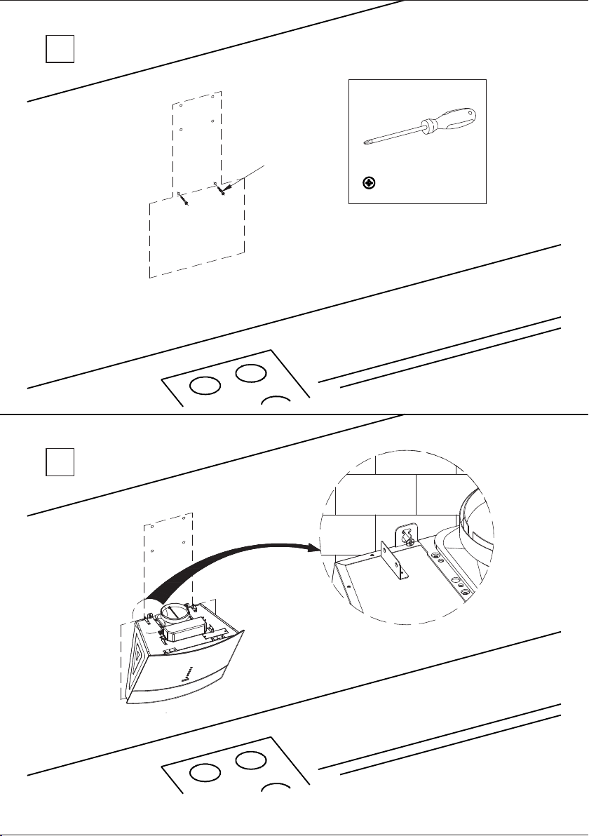
INSTALLATION REQUIREMENTS
1.Do not install the cooker hood where there are many doors or windows,
to avoid effecting the exhaust efficiency of the hood caused by air
convection.(Fig. 1)
2.Install the cooker hood right above the hob. The recommended
distance between the hob and the lower edge of the cooker hood show as
below. (Fig. 2)
3.To obtain optimum performance, the external conduct must not be more
than FOUR METRES long, have no more than two 90° angles and its
diameter must be at least Ø120. (Fig. 3)
4.After hanging the unit on the wall, ensure the hood is level and vertical.
5.The air outlet must not be connected to chimney flues or combustion
gas ducts. The air outlet must under no circumstances be connected to
ventilation ducts for room in which fuel-burning appliances are installed.
Fig.1
Fig.2 Fig.3
400~450mm
4

INSTRUCTIONS FOR USE
Switch on the extractor fan a few minutes (between 3 to 5 minutes) before
you start to cook in order to ensure that a steady air flow has been
established before fumes appear.
Allow the extractor fan to run for several minutes after you have finished
cooking (between 3 to 5 minutes) in order to expel all the grease from the
outlet duct. This prevents the return of grease, smoke and smells.
DVC560B/DVC560W
Touch to select on/off
During operation mode,touch 1(one) time to select OFF and the fan turns
off automatically after 1(one) minute. Touch 2(two) times, and the fan
turns off instantaneously.
Light key
Touch to select on/off
Timer
Touch to select on/off
1.Clock: In stand-by mode press the key for 3 seconds to set the clock.
Press the speed key to set hours, press the high speed key for increase
the hours, press the low speed key for decrease the hours. The n press
again timer key to set the minutes. Press high speed key for increase the
minutes, press the low speed key to decrease the minutes. Press timer
key for the third time to confirm the clock setting or it will be automatically
saved within 5 seconds if no operation has been performed.
2. Timer (working time): When the appliance is operating or the light is
on press timer key to set working time – the indicator will start to blink.
Each press increases the value by 1 minute (maximum setting is 60
minutes). If no operation has been performed within 1 0 seco nds – the
appliance will start operating with the default set working time, i.e.1
minute. Note: In standby mode, you cannot set working time.
High speed key
Press to select the high speed
Mid speed key
Press to select the mid speed
Low speed key
Press to select the low speed
5

DVU560B/ DVU560W/ DVU590B/ DVU590W
Note: This appliance is equipped with an automatically opening/
closing glass panel.
Be particularly careful as not to trap your fingers or other part of
your body in the glass panel.
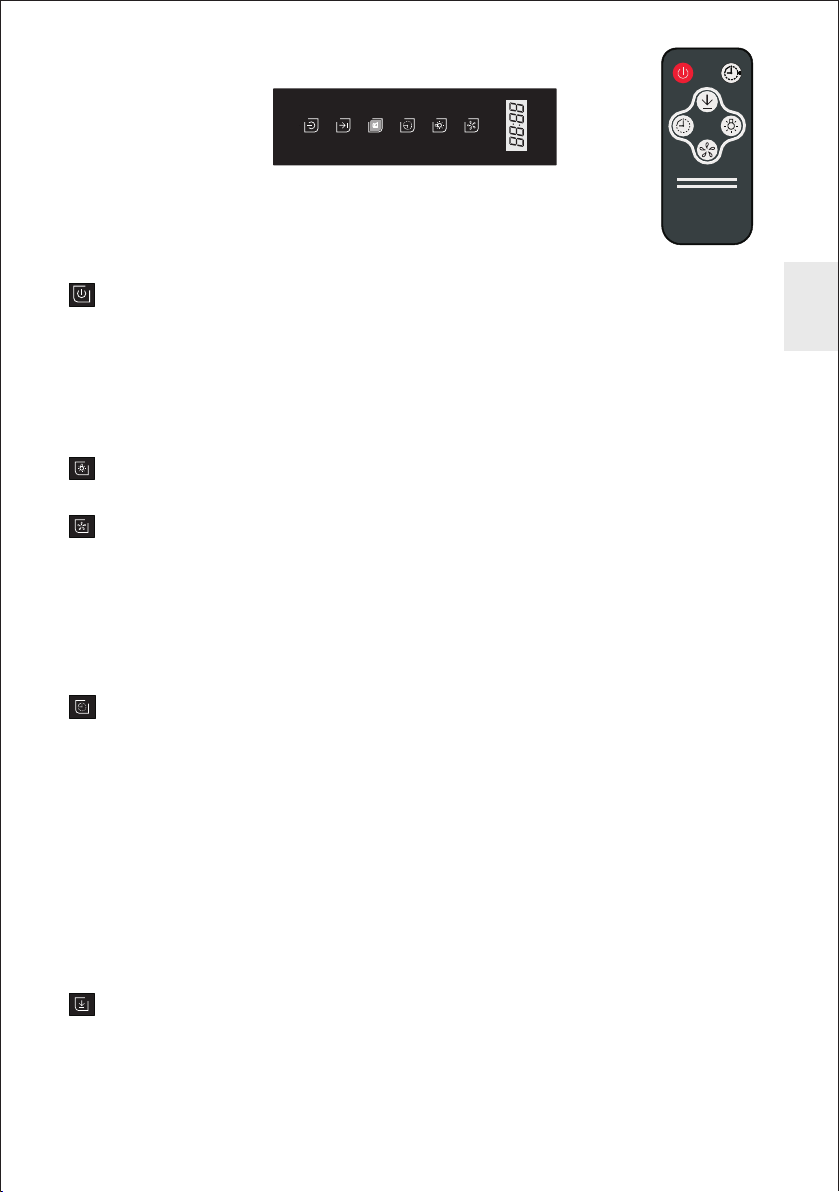
Touch to select on/off
During operation mode, touch 1(one) time to select OFF and the fan turns off
automatically after 1(one) minute. Touch 2(two) times, and the fan turns off
instantaneously.
Note: Using the remote control, turn on the appliance by pressing speed
function key (it will start operating at speed F3). Turn off the appliance by
pressing the ON/OFF key.
Touch to turn the light on/off
Speed function key
Touch one time show“F3”to select the high speed.
Touch twice show“F2”to select the medium speed.
Touch thrice show“F1” to select the low speed.
The screen shows cycle , F3-F2-F1.The fan speed in cycle operation, high
speed-medium speed-low speed.
When on Delay and Timer status, Press this key,the delay and timer function
would be closed, and motor will switch to next speed working.
Timer
1.Clock: In stand-by mode press the key to set the clock. Press once the speed
function key to set the hours (change by 1 hour, maximum setting is 24 hours).
Press once the light key to set the minutes (change by 1 minute, maximum
setting is 60 minutes). Press again timer key or do not perform any operation
within 5 seconds - the appliance will automatically save the current clock
setting, and then return into standby mode.
2.Timer (working time): When the appliance is operating, press the key to set
working time. Press once to set the minutes (change by 1 minute, maximum
setting is 60 minutes). In timer mode, the appliance will start countdown after
10 seconds if no operations are performed. When the countdown / working
time has finished, the turbine stops operating, a beep will sound, the glass
panel will close automatically, and the appliance will return into standby
mode.
Locking function key
1 In standby state, touch the key keep 3 seconds ( fo r remote control , less
than 3 seconds) , until the indicator lamp flash, then the door slowly open
and keep the locking state, the users could cleaning the filters.
2 After cleaning touch the ON/OFF key, last 3 seconds (for remote control,
less than 3 seconds) , the hood would be closed automatically and back to
the standby mode.
6

Safety function
1 While locking the glass panel , when the opening / closing glass panel
encounters obstacle / resistance, it will move in the opposite direction and
then start opening/closing again.
2 If the glass panel encounters obstacle/resistance after the turbine starts/
stops operating , it will stop/lock and the appliance will return into standby
mode.
CLEANING AND MAINTENANCE
CAUTION: NEVER PUT YOUR HAND INTO THE AREA HOUSING THE FAN
WHI LE TH E FA N I S OP ERATI NG. FO R THE O PTIMA L LE VEL OF
OP ER ATI ON , CL EA N T HE R ANG E H OOD S UR FA C E, FAN , AN D
ALUMINIUM FILTER REGULARLY.
1. Use only mild soap or detergent solutions to clean the cooker hood
surface. Dry surfaces using soft cloth.
2 .Using a stainless steel cleaner to bring the glow back into a stainless steel finish.
3. Clean the filter once a week or according to use status. Press the buckle
of the filter slightly, take off the filter and put it into warm soapy water using
mild detergent, wipe the filter with soft brush. Replace the filter after it is dry.
4 .It is recommended to clean the housing and inner surfaces at least once
every half year or depending on the degree of soiling.
5. Do not use aggressive cleaning agents (i.e. scrubbing or scratching).
6. For cleaning, do not use steam cleaners.
REPLACING LIGHT BULB
To replace LED lamp
Caution: LED lamp cannot replace a new bulb, just can replace a new LED
Lamp. Mak e sure all the co ntrol sw itche s are off, and the coo ker hoo d is
unplugged! Please follow below instructions:
1.Take out the filters, and cut off the wire connection of the lamp.
2.Press the spring according to the arrow direction, then you can take off the
lamp unit.
3.You can replace a new LED lamp unit no more than rating!
4.Then put the lamp unit to the hood in reverse direction. Connect the wire
of the lamp.
5.Fit on the filters.
7

PROBLEM SOLVING
CAUTION: Disconnect the power supply before servicing.
8

SPIS TREŚCI
ŚRODKI OSTROŻNOŚCI I OGÓLNE ZALECENIA
DANE TECHNICZNE............................................................................3
SPECYFIKACJA..................................................................................3
ELEMENTY URZĄDZENIA....................................................................4
WYMOGI MONTAŻOWE ......................................................................4
OBSŁUGA URZĄDZENIA .................................................................5-6
CZYSZCZENIE I KONSERWACJA........................................................7
WYMIANA OŚWIETLENIA....................................................................7
ROZWIĄZYWANIE PROBLEMÓW................................................... . ...8
FILTRY Z WĘGLA AKTYWNEGO (OPCJA)...........................................8
.............................1-2

Ni n iej s ze u rząd z eni e je s t pr z ezn a czon e d o
oczyszczania powietrza z dymu, spalin , oparów,
zapachów I innych niepożądanych zanieczyszczeń,
które gromadzą się w kuchni w t r ak c i e o b r ób k i
c i e p ln e j p ro d u kt ów ży wno ściow ych .
1

2

DANE TECHNICZNE
Model: □ DVC560B □ DVC560W □ DVU560B □ DVU560W □ DVU590B
□ DVU590W
Maksymalny pobór mocy: 204 W
Moc silnika: 200 W
Oświetlenie LED: 2 x 2W
Napięcie znamionowe: 220 ~ 240V
Częstotliwość: 50Hz
Typ filtra metalowego: 3-warstwowy
Sterowanie: □ sensorowe □ sensorowe + pilot
SPECYFIKACJA
Wymiary
DVC560B/D VC560W(s zer.*dł.* wys.):60 0*410*99 9~1380
DVU560B/D VU560W(s zer.*dł.* wys.):60 0*428*99 9~1380
DVU590B/D VU590W(s zer.*dł.* wys.):90 0*432*10 01~1391
DVC560B/D VC560W
Wydajność maksymalna - 760m³/h
Wydajność silnika - max. (m³/h ) - 633m³/h
Wydajność silnika – w obiegu otwartym (m³/ h) - 553m³/h
Wydajność prędkość 1 (niska) - 431m³/h
Wydajność prędkość 2 (średnia) - 478m³/h
Wydajność prędkość 3 (wysoka) - 518m³/h
Poziom hała su wg normy UN E-EN-607 04-2-13 (d BA)
Prędkość 1 (n iska) - 50.3 7 dBA
Prędkość 2 (ś rednia) - 56 .43 dBA
Prędkość 3 (w ysoka) - 59. 06 dBA
DVU560B/D VU560W/D VU590B/D VU590W
Wydajność maksymalna - 760m³/h
Wydajność silnika - max. (m³/h ) - 633m³/h
Wydajność silnika – w obiegu otwartym (m³/ h) - 553m³/h
Wydajność prędkość 1 (niska) - 443 m³/h
Wydajność prędkość 2 (średnia) - 493m³/h
Wydajność prędkość 3 (wysoka) - 538 m³/h
Poziom hała su wg normy UN E-EN-607 04-2-13 (d BA)
Prędkość 1 (n iska) - 49.8 4 dBA
Prędkość 2 (ś rednia) -5 5.84 dBA
Prędkość 3 (w ysoka) -58 .43 dBA
3

ELEMENTY URZĄDZENIA
Wieszak Wieszak
Górna osłona
wentylacyjna
Dolna osłona
wentylacyjna
Przewód
odprowadzający
okapu
Wylot powietrza Wylot powietrza
Korpus okapu Korpus okapu
DVC560 B
DVC560 W
Górna osłona
wentylacyjna
Dolna osłona
wentylacyjna
Przewód
odprowadzający
okapu
DVU560 B/DVU56 0W
DVU590 B/DVU59 0W
WYMOGI MONTAŻOWE
1 Nie instalować urządzenia w pomieszczeniach o dużej liczbie drzwi lub
oki en , gd yż w pł yw a to n eg at yw ni e na e fe kt yw no ść p ra cy ok ap u
kuchennego (rys. 1).
2 Zamon tow ać ok ap b ezpo śre dnio nad p łytą kuc henną. Zalecaną
odleg łoś ć mię dzy doln ą pow ier zchn ią w ycią gu a płytą kuc he nną
przedstawiono poniżej (rys. 2).
3 Aby zapewnić optymalne parametry pracy okapu, przewód wentylacyjny
nie może być dłuższy niż 4 metry, posiadać maksymalnie 2 kolanka 90°,
a jego średnica nie może być mniejsza niż ř Ф120 mm (rys. 3)
4 Po zamontowaniu okapu na ścianie należy upewnić się , że został
właściwie wypoziomowany.
5 Nie po dłą czać prze wod u wen tyl acyj neg o oka pu do p rz ewodó w
oddymiających lub odprowadzania spalin gazowych. W żadnym wypadku
nie należy podłączać go do przewodów wentylacyjnych pomieszczenia,
do których są odprowadzane spaliny z urządzeń grzewczych..
Rys. 1 Rys. 2 Rys. 3
400~450mm
4

OBSŁUGA URZĄDZENIA
Zaleca się włączenie wyciągu na kilka minut przed rozpoczęciem got owan ia
(3 - 5 minut), w ten sposób tworzy się stabilny ciąg powietrza j e szcz e pr ze d
powstaniem oparów.
Zaleca się również pozostawienie wyciągu włączonego ( 3 - 5 minut ) po
zakończeniu gotowania, co umożliwia wydmuchanie wszelkich opa ró w i
tłuszczów z przewodów wentylacyjnych i zapobieg a ich cofaniu się do
pomieszczenia.
DVC560B/DVC560W
Przycisk włączenia/wyłączenia ON/OFF
Podczas p r acy oka p u nacis n ąć przy c isk 1 ra z – urzą d zenie w ył ącz y s i ę
au tomatycznie po upływi e 1 minuty . Nacis nąć przyci sk 2 r azy – urządzenie
natychmiast wyłączy się.
Przycisk włączenia/wyłączenia oświetlenia
Oświetlenie włączone – wskaźnik podświetli się.
Przycisk Timer
1 Zegar: Gdy urządzenie znajduje się jest w trybie czuwania, na c iskać przy c isk
przez 3 sekundy, by ustawić zegar. Za pomocą przycisku wyboru pr ę dkości
wysokiej lub wyboru prędkości niskiej u stawić w artość g odziny. Nacisną ć
ponownie przycisk timer, by ustawić wartość minut. Z a pom o cą pr zyc isk u
wyboru prędkości wysokiej lub wyboru prędkości nis k iej ust a wić wła ś ciwą
wartość minut. Nacisnąć przycisk timer po raz trzeci, by potwierdzić ustawienie
zegara lub urządzenie automatycznie zapamięta bieżące ustawienie zegara,
jeśli w ciągu 5 sekund nie wykonano żadnej czynności.
2 Timer: Gdy działa turbina lub włączono oświetlenie, nacisnąć przycisk, by
ustawić c z as prac y okapu - wskaźni k zacznie m igać. K a żde na ci ś ni ę ci e
zwiększa wartość o 1 minutę (maksymalne ustawienie to 60 minut). Gdy w ciągu
10 sekund nie wykonano żadnej czynności – urządzenie rozpocznie pracę z
domyślni e ustawio n ym czas e m, któr y wynosi 1 minutę . U wag a: W t rybie
czuwania, nie można ustawić czasu pracy okapu.
Przycisk wyboru prędkości wysokiej
Gdy urządzenie znajduje się w trybie czuwania, nacisnąć przycisk, wskaźnik
podświetli się: turbina działa z wysoką prędkością.
Ponownie nacisnąć przycisk, turbina zatrzyma się.
Przycisk wyboru prędkości średniej
Gd y urząd zenie znajd uje się w trybie czuwania, nacisnąć przycis k, wskaź nik
podświetli się: turbina działa ze średnią prędkością.
Ponownie nacisnąć przycisk, turbina zatrzyma się.
Przycisk wyboru prędkości niskiej
Gdy urządzenie znajduje się w trybie czuwania, nacisnąć przycisk, wskaźnik
podświetli się: turbina działa z niską prędkością.
Ponownie nacisnąć przycisk, turbina zatrzyma się.
5

DVU560B/ DVU560W/ DVU590B/ DVU590W
Uw aga: Urząd zenie wypos ażono w automatycznie otwierając y/
zamykają c y się pa n el szkl a ny. Nal e ży zach o wać szc z ególną
ostrożność, by nie przytrzasnąć palców ani innej części ciała między
panelem szklanym a obudową okapu.
Przycisk włączenia/wyłączenia ON/OFF
Podczas p r acy oka p u nacis n ąć przy c isk 1 ra z – u r ząd ze ni e wy łą c zy si ę
automaty c znie po u pływie 1 minut y. N a cisnąć prz y cisk 2 razy – u rz ąd ze ni e
natychmiast wyłączy się.
Uw aga: Używa jąc pilota, włączyć urządzenie za pomo cą przycisk u wyboru
prędkości ( okap rozpocznie pracę z prędkością F3 ) . Wyłącz yć urzą d zenie
naciskając przycisk włączenia/wyłączenia ON/OFF.
Przycisk włączenia/wyłączenia oświetlenia
Przycisk wyboru prędkości
Nacisnąć przycisk 1 raz, pojawi się symbol "F3" – wybór wysokiej prędkości.
Nacisnąć przycisk 2 razy, pojawi się symbol "F2" – wybór średniej prędkości.
Nacisnąć przycisk 3 razy, pojawi się symbol "F1" – wybór niskiej prędkości.
Na wyświetlaczu pojawią się kolejno F3, F2, F1 – prędkości turbiny w kolejności
działania, tj. prędkość wysoka – prędkość średnia – prędkość niska.
Jeśli naciśnięto przycisk wyboru prędkości w trakcie odliczania czasu pracy
okapu, urządzenie zakończy odliczanie, zaś turbina będzie pracować z następną
prędkością w kolejności działania.
Przycisk Timer
1 Zegar: Gdy urządzenie znajduje się w trybie czuwania, nacisnąć przycisk, by
ustawić zegar. Nacisnąć przycisk wyboru prędkości 1 raz, by ustawić wartość
godziny (zmiana o 1 godzinę, maksymalne ustawienie to 24 godziny). Nacisnąć
przycisk włączenia/wyłączenia oświetlenia 1 raz, b y ustawić w artość minut
(zmiana o 1 minutę, maksymalne ustawienie to 60 minut). Nacisnąć ponownie
przycisk t imer lu b nie wyko n ywać ża d nej czy n ności w c iągu 5 s e kund urządzenie automatycznie zapamię ta bieżące ustawienie zegara, a następnie
powróci do trybu czuwania.
2 Timer ( czas pracy ok apu ): Gdy urz ądzenie dz iała, nacis nąć przycis k , by
ustawić czas pracy okapu. Nacisnąć przycisk 1 raz, by ustawić wartość minut
( zmiana o 1 minutę, maksymalne ustawienie to 60 minut ). W trybie timera,
urządzen i e rozpo c znie od l iczani e po upływ i e 10 s ek un d , w p rz yp ad ku
niewykonania żadnej czynności. Po zakończeniu o dliczania/czasu pracy okapu,
turbina zatrzyma się, rozlegnie się sygnał dźwiękowy, panel szklany zamknie się
automatycznie, zaś urządzenie powróci do trybu czuwania.
Przycisk blokady panelu szklanego
1 Gdy urządzenie znajduje się w trybie stand-by, naciskać przycisk przez 3
sekund y ( używa jąc p ilota – kró cej ni ż 3 sek undy ) aż zaczn ie miga ć
wskaźnik blokady. Po włączeniu blokady panel szklany powoli otworzy się,
istnieje możliwość wyczyszczenia filtrów metalowych.
2 Po wyczyszczeniu, na c iskać przycisk w łącz enia/ wyłą c zeni a ON/OFF
przez 3 sekundy ( używając pilota – krócej niż 3 sekundy), panel szklany
zamknie się automatycznie, urządzenie powróci do trybu stand-by.
6

Funkcja bezpieczeństwa
1 Pod cz as b lo kow an ia p an el u sz kl ane go , w m om enc ie g dy otwi erają cy
/zamykający się panel napotka opór zatrzyma się, wykona ruch w przeciwnym
kierunku, a następnie zacznie otwierać/zamykać się.
2 Jeśli po włączeniu/wyłączeniu turbiny panel szklany napotka opór podczas
otwierania/zamykania się, wtedy panel zatrzyma się, a urządzenie powróci
do trybu stand-by.
CZYSZCZENIE I KONSERWACJA
UWA GA ! NIE W OLN O WK ŁAD AĆ R Ą K DO W NĘ TRZ A URZĄ DZE NIA , GD Y
S IL NI K NA DA L D ZI AŁ A . P RZ YS TĘ PU JĄ C DO C Z Y S Z C Z E N I A I
KONSERWACJI NALEŻY ODŁĄCZYĆ URZĄDZENI E OD ZASILANIA.
BY ZAPEW NIĆ OPTY MALNĄ PR ACĘ URZĄ DZENIA, NALEŻY REGULARNIE
CZYŚCIĆ O BUDOWĘ O RAZ FILTRY METALOWE.
1 Urządzenie czyścić za pomocą łagodnych środków czyszczących/detergentów
do mycia szkła. Wytrzeć do sucha miękką ściereczką.
2 Zaleca się czyścić/polerować powierzchnie ze stali szlachetnej specjalnym
środkiem przeznaczonym do pielęgnacji tego rodzaju powierzchni.
3 Filtr metalowy czyścić raz w tygodniu lub w zależności od stopnia zabrudzenia.
Zwolnić blokadę, wyjąć filtr z mocowania, namoczyć w ciepłej wodzie z dodatkiem
płynu do mycia naczyń , spłukać pod bie żącą wodą. Po umyciu filtr na leży
dokładnie wysuszyć.
4 Zaleca się czyścić obudowę oraz powierzchnie wewnętrzne co najmniej raz
na pół roku lub w zależności od stopnia zabrudzenia.
5 Nie wolno stosować agresywnych środków czyszczących (tj. szorujących lub
rysujących).
6 Do czyszczenia nie używać urządzeń parowych.
WYMIANA OŚWIETLENIA
Wymiana oświetlenia typu LED
Uwaga! Zużytą lampę LED można wymienić wyłącznie na nową lampę LED (nie
stosować lamp żarowych ani halogenowych).
Upewnić się, że urządzenie odłączono od sieci zasilającej. Następ n ie wykonać
następujące czynności:
1 Wyjąć filtry metalowe.
2 Wypchnąć na zewnątrz zespół lampy, rozłączyć przewód zgodnie z kierunkiem
strzałek.
3 Zamontować nową lampę LED (o tych samych parametrach).
4 Z powrotem podłączyć przewód lampy, zamocować zespół lampy w urządzeniu.
5 Zamocować filtry metalowe.
7
ROZWIĄZYWANIE PROBLEMÓW
UWAGA! Przed przystąpieniem do naprawy odłączyć urządzenie
od sieci zasilającej.
PRAWDOPODOBNA PRZYCZYNAPROBLEM NARZĘDZIE
Uszkodzony przewód
zasilający.
Silnik nie działa. A – Turbina jest zablokowana. Sprawdzić turbinę, upewnić się, że została
Okap wibruje.
Okap działa zbyt
głośno.
Okap nie pochłania
wystarczająco.
Oświetlenie nie
działa.
Wymiany uszkodzonego przewodu elektrycznego powinien dokonać
autoryzowany serwis techniczny lub odpowiednio wykwalifikowana osoba.
poprawnie zamontowana.
B – Silnik jest zablokowany. Sprawdzić silnik, upewnić się, że został poprawnie
zamontowany.
C – Silnik zepsuł się. Wymienić silnik.
D – Panel sterujący zepsuł się. Wymienić panel sterujący.
E – Kondensator zepsuł się. Wymienić kondensator.
A – Niepoprawny (niezbyt mocny) montaż całego urządzenia. Sprawdzić oraz
poprawić montaż urządzenia.
B – Turbina zepsuła się. Wymienić turbinę.
C – Niepoprawny montaż korpusu okapu. Sprawdzić oraz poprawić montaż
korpusu okapu.
D – Niepoprawny montaż silnika. Sprawdzić oraz poprawić montaż silnika.
A – Niepoprawny montaż turbiny. Dokręcić śruby mocujące turbinę lub wymienić
turbinę.
B – Ciała obce dostały się do turbiny. Sprawdzić oraz wyczyścić turbinę.
A – Nieprawidłowa odległość między dolną powierzchnią okapu a płytą kuchenną.
Prawidłową odległość przedstawia rysunek 4.
B – Zbyt wiele okien i drzwi w pomieszczeniu, w którym zamontowano okap.
Zamknąć część okien oraz drzwi, by zmniejszyć zakłócenia w cyrkulacji
powietrza.
C – Wiatr wlatuje do przewodu odprowadzającego okapu. Upewnić się, że
przewód odprowadzający jest zamontowany w dół (patrz rys. 3). Sprawdzić
cyrkulację powietrza w przewodzie wentylacyjnym.
D – Nastąpiło zużycie silnika lub kon densatora. Wymienić silnik lub kondensator.
Wymienić lampę LED lub zespół lampy. Wkrętak typu „+”
Wkrętak typu „+”,
ostre szczypce
Wkrętak typu „+”
Wkrętak typu „+”
Wkrętak typu „+”
Wkrętak typu „+”
Filtry z węgla aktywnego (opcja)
W p rzyp adku braku możli woś ci odprowa dzania opa rów na zewną trz,
należy zainstalować filtry z węgla aktywnego.
Skute czn ość działa nia fi ltrów węgl owy ch wynosi od 3 do 6 mi esi ęcy
zależnie od intensywności użycia. Filtrów tych nie można czyścić ani
regenerować. Należy zamontować nowe filtry.
Pr odu cen t za str zega sob ie p rawo d o w prow adz ania z mi an w
sw oic h u rzą dzen iac h, j eśli ty lko u zna j e z a kon iec zne b ądź
użyte czn e, bez szkody dla ogólnego funkcjonowania urządzenia.
8

İÇİNDEKİLER
GÜVENLİK TALİMATI……………………………………………………1-2
TEKNİK ÖZELLİKLERİ ……………………………………………………3
ÖZELLİKLERİ
ANA PARÇA İSİMLERİ……………………………………………..………4
TR
MONTAJ GEREKSİNİMLERİ………………………………………….…..4
KULLANIM TALİMATLARI………………………………………………5-6
TEMİZLİK VE BAKIM ……………………………………………….…….7
LAMBANIN DEĞİŞTİRİLMESİ ………………………………………..…7
SORUN GİDERME …………………………………………………………8
AKTIF KARBON FILTRELER (IST BA lı)...... ... ....... ...... ...8
……………………………………………..………………3
ĞE Ğ ………

Değerli Müşterimiz:
Bizi seçtiğiniz için teşekkürler.
Modern, işlevsel ve pratik, birinci
sınıf malzemelerden üretilmiş bu
c i h a z ı n t üm iht i y aç l a rın ı zı
karşılayacağından eminiz.
Küç ük so run la rın çöz ülm es ine
o l a n a k s a ğ l a y a r a k h a t a l ı
kullanım dan ka ynaklan abi lec ek
arızaları önlemek ve cihazın en
ü s t d ü z e y d e p e r f o r m a n s
g ös te r me s ini s a ğl am a k i ç in
davlumbazı ilk kez kullanmadan
ö n c e b u K U L L A N I M
KILAVUZUNUN tüm bölümlerini
okuyun.
Optimum performans elde etmek
için dış boru DÖRT METRENİN
üze ri nd e ol ma ma lı , ik i 90° ’l ik
açının üzerinde olmalı ve çapı
Ø120’nin altında olmalıdır.
Bu cihaz, duman, yanıcı ürünler,
k ok ul a r v e mut fa k iç e ri si n de
ür ün ler in ıs ıt ılm as ı es nası nd a
oluşan diğer istenmeyen yabancı
maddelerden havanın temizlenmesi
için tasarlanmıştır.
Güvenlik Talimatlarý
• Temizlik ve bakım gibi iç kısımda
herhangi bir çalışma yapmadan
önce cihazın bağlantısını kesin.
• Davlumbaz ve metal filtrelerde
aş ırı yağ bi riki mi y ang ın v e
damlama riskine neden olur, bu
nedenle davlumbazın ve metal
filtrelerin iç kısmını ayda en az bir
kez yıkamak gerekir.
• B u c i ha z g öz e ti m a lt ınd a
t u t u l m a l a r ı v e y a c i h a z ı n
kullanımına ilişkin uygun şekilde
bi lg ile nd iril me leri ve iç er diğ i
tehlikeleri anlamaları durumunda
8 yaş ve üzeri çocuklar fiziki,
duyu sal ve me tal ka pas ite ler i
düşük veya yete rsiz bilgi ve
d e n e y i m e s a h i p k i ş i l e r
t a r a f ı n d a n k u l l a n ı l a b i l i r.
Çocuklar cihazla oynamamalıdır.
K u l l a n ı c ı t a r a f ı n d a n
gerç ekl eştirile cek te miz lik ve
bakım çalışmaları gözetimsiz bir
şe kild eç oc uk la rh ta raf ın dan
yapılmamalıdır.
• Ş e b e k e v o l t a j ı n ı n v e
f r e k a n s ı n ı n d a v l u m b a z ı n
i çe ri s in de b u lu na n e ti k et te
belirtilen değerleri karşıladığını
kontrol edin. İyi bir topraklama
yapı lmalı dır (isi m levhas ınd a
s ın ı f I I o l ar ak i şa re t le n en
cihazlar hariç ).
• Montaj için, acil durumlarda,
t e m i z l i k v e y a l a m b a n ı n
d e ğ i ş t i r i l m e s i s ı r a s ı n d a
b a ğl an t ı nın k es il me s i i çi n
kategori III koşulları uyarınca
(kontaklar arasında minimum 3
mm ’l ik bi r aç ıkl ık ve c ih azı
destekleyecek yeterli dayanımla
birlikte) montaj yönetmeliklerine
göre bağlantının sabit montajdan
tamame n kesilmesine yön elik
araçlar bulundurulmalıdır. Hiçbir
durumda topraklama kablosu bu
devre kesiciden geçmemelidir.
Bu devre kesici normal kullanım
sırasında erişilebilmesi kaydıyla
bir anahtarlı prizle değiştirilebilir.
• Be sle me kabl osu nu n has ar
görmesi durumunda bir tehlikeyi
ö nl em e k i ç in ü ret ic i , s a tı ş
sonrası servisi veya nitelikli bir
kişi tarafından değiştirilmelidir.
• Tahliye edilen hava gaz veya
d i ğ e r y a k ı t l a r l a b e s len e n
ci ha zl ar ın dumanı nı t ah li ye
etmek için kullanılan borulardan
gönderilmemelidir.
TR
1

• D a v l u m b a z a y n ı a n d a
elektrikten farklı bir enerji ile
b e s l e n e n c i h a z l a r l a
ku ll an ıla ca ks a o dad a u yg un
ha va lan dır ma s ağ la nma lı dı r,
örn: gazlı ocaklar.
•Davlumbaz ve metal filtrelerde
aş ır ı y ağ b ir iki mi y an gın ve
damlama riskine neden olur, bu
nedenle davlumbazın ve metal
filtrelerin iç kısmını ayda en az bir
TR
kez yıkamak gerekir.
• D a v l umb a zın a l t ı n d a a le v
yasaktır.
•Davlumbazın iç kısmı gazlı veya
karma set üstü ocaktan en az
65cm uzakta bulunmalıdır. Set
üs tü o cağ ın m ini mum üre ti m
göstergelerine uyun.SET ÜSTÜ
O CA Ğ IN M İN İMU M Ü R ET İ M
GÖ ST ERG EL ERİ . Bu m es af e
d a v l u m b a z ı n m o n t a j
t a l i m a t l a r ı n d a b el i r t i l m e s i
durumunda düşürülebilir.
•Kapatan bir tava olmadan asla
ga z b rülör le ri ni y an ar ha ld e
bırakmayın. Filrelerde biriken yağ
s ı c a k l ı k a r t ı ş ı n e d e n i y l e
damlayabilir veya alev alabilir.
•M et al fi lt re ler t ak ılı d eğ ils e,
ör ne ği n b ul aşı k ma ki ne sind e
te mi zl eni rl er ken da vl um baz ın
a l t ı nda y e m e k p iş i rm e kt e n
kaçının.
• D a v l u m b a z ı n i ç k ı s m ı n ı
temizlerken eldiven kullanılmasını
v e ç o k d i k k a t e d i l m e s i n i
öneriyoruz.
•Davlumbaz evde kullanım için ve
y a l n ı z c a g ı d a l a r ı n
haz ırla nması nd a or ta ya ç ık an
gazların tahliyesi ve temizlenmesi
i ç i n t a s a r l a n m ı ş t ı r . B a ş k a
a m a ç l a rl a k u l l an ı m ı k e nd i
sorumluluğunuzdadır ve tehlikeli
olabilir. Üretici cihazın uygunsuz
k u lla nı mı nd an k a y na kl an an
ha sa rla rda n s or uml u d eğ ild ir.
• Herhangi bir onarım için yalnızca
or ij in al p ar ça la r k ul la nı la ra k
üreti cini n en yakındaki Teknik
Destek Servisine başvurulmalıdır.
N it e lik s iz k iş i le r t ar a fı n da n
gerçekleştirilen onarımlar veya
d e ğ i ş i k l i k l e r g ü v e n l i ğ i n i z i
tehlikeye sokarak cihazın zarar
g ö r m e s i n e v e y a h a t a l ı
çalışmasına neden olabilir.
• Bu cihaz “Elektrikli ve Elektronik
Cihaz Atıkları” olarak tanımlanan
elektrikli ve elektronik cihazlara
i l i ş k i n 2 0 0 2 / 9 6 / C E A v r u p a
Y öne r g es i’ n e u y g un du r. B u
yönerge elektrikli ve elektronik
c i h a z l a r ı n i a d e s i v e g e r i
dönüşümü için tüm Avrupa birliği
k a p s a m ı n d a g e ç e r l i g e n e l
u y g u l a m a y ı
vermektedir.denetlenmelidirler.
2

TEKNİK ÖZELLİKLERİ
Model No.: □ DVC560B □ DVC560W □ DVU560B □ DVU560W
□ DVU590B □ DVU590W
Toplam Güç: 204 W
Motor Güç: 200 W
LED Işıkları: 2 x 2W
Voltaj: 220 ~ 240V
Frekans: 50Hz
Filtre: 3 katmanlı filtre
Kontrol: □Soft Dokunmatik Kontrol
□Soft Dokunmatik Kontrol + Uzaktan kumanda
ÖZELLİKLERİ
Boyu tla r
DVC560B/DVC560W(W*D*H):600*410*999~1380
DVU560B/DVU560W(W*D*H):600*428*999~1380
DVU590B/DVU590W(W*D*H):900*432*1001~1391
DVC560B/DVC560W
Maks imu m çıkış kapasite 760m³ / h
Moto r çıkış kapasitesi -Max. (m³/h)-633m³/h
Moto r çıkış kapasitesi - Serbest hava çıkışı (m³/h) -553m³/h
Çıkış Kapasite 1. hız - 431m³ / h
Çıkış Kapasitesi 2. hız - 478m³ / h
Çıkış Kapasite 3. hızı - 518m³ / h
TR
Ses Se viyesi UNE-EN-60704-2-13 (dBA)
1. hız - Ses Seviyesi -50,37 dBA
2. hız - Ses Seviyesi -56,43 dBA
3. hız - Ses Seviyesi -59,06 dBA
DVU560B/DVU560W/DVU590B/DVU590W
Maks imu m çıkış kapasite 760m³ / h
Moto r çıkış kapasitesi -Max. (m³/h)-633m³/h
Moto r çıkış kapasitesi - Serbest hava çıkışı (m³/h) -553m³/h
Çıkış Kapasite 1. hız - 443m³ / h
Çıkış Kapasitesi 2. hız - 493m³ / h
Çıkış Kapasite 3. hızı - 538m³ / h
Ses Se viyesi UNE-EN-60704-2-13 (dBA)
1. hız - Ses Seviyesi -49.84 dBA
2. hız - Ses Seviyesi -55.84 dBA
3. hız - Ses Seviyesi -58.43 dBA
3

ANA PARÇA ADLARI
Kanca
İç Boru Ma hfazası
Dış Boru M ah faz ası
Egzoz Bo rusu
Hava ç ıkışı
Vant ilatö r kutusu
DVU560 B/DVU56 0W
DVU590 B/DVU59 0W
TR
Kanca
İç Boru Ma hfazası
Dış Boru M ah faz ası
Egzoz Bo rusu
Hava ç ıkışı
Vant ilatö r kutusu
DVC560 B
DVC560 W
MONTAJ ŞARTLARI
1. Hava akımından kaynaklanan davlumbazın egzoz verimliliğinin
etkilenmesini önlemek için davlumbazı birçok kapının ve pencerenin
olduğu yere takmayın (Sekil 1).
2.Davlumbazı ocağın tam üstüne yerleştirin. Ocak ve davlumbaz alt
kenarı arasındaki tavsiye edilen mesafe aşağıda gösterilmektedir
(Sekil 2).
3.En iyi performansı elde etmek için, dış yollar DÖRT METREDEN
fazla uzun olmamalı, iki 90 º den fazla açıya sahip olmamalı ve
çapı en az Ø120 olmalıdır (Sekil 3).
4.Üniteyi duvara astıktan sonra, davlumbazın düzlenmiş ve dikey
olduğundan emin olun.
5.Hava çıkışı, bacalara veya yanıcı gaz kanallarına bağlı olmamalıdır.
Hava çıkışı, hiçbir ko şul altında yakıtlı ısıtıcıların olduğu odalara bağ
lanmamalıdır.
Şekil 1
Şekil 2
Şekil 3
400~450mm
4

KULLANIM TALİMATLARI
Duman görünmeden önce sürekli hava akışının sağlandığından emin
olmak için davlumbazı birkaç dakikalığına açın (3- 5 dakika arasında).
Pişirme işleminizi tamamladıktan sonra, tüm yağın çıkış kanalından
atılması için davlumbazı birkaç dakikalığına ( 3- 5 dakika arasında)
çalıştırın. Bu yağın, dumanın ve kokuların dönüşünü önleyecektir.
DVC560B/DVC560W
TR
On/ Off u s eçmek i çin dok unu n.
Çalı şma mod u sı ras ınd a, O FF u se çme k iç in 1 (b ir) kez dokunun ve
fan 1 otomat ik olar ak 1 da kika so nra kap anı r. 2(ik i) kez doku nun ve
anın da k apa nır.
Işık tuşu
On/Off u seçmek için dokunun.
Zamanlayıcı
On/Off u seçmek için dokunun.
1.Saat: Stand-by modunda, saati ayarlamak için 3 saniye süreyle
düğmeye basın. Saati ayarlamak için hız tuşuna basın, saati artırmak
için yüksek hız tuşuna basın, saatleri azaltmak için düşük hız tuşuna
basın. Daha sonra, dakikaları ayarlamak için yeniden zamanlayıcıya
bası n. Dakikaları artırmak i çin yüks ek hız tuşuna ba sın, dak ikaları
azal tma k için dü şük hız tuşun a basın. Saat ay arını on aylamak için
üçüncü kez zamanlayıcıya basın veya hiçbir işlem yapılmazsa 5 saniye
içinde otomatik olarak kaydedecektir.
2. Zamanlayıcı (çalışma süresi): Cihaz çalıştığı veya ışığı açık olduğu zaman,
çalı şma sür e si n i aya r la m ak i çi n z a ma nlay ıcı ya ba s ın – G öst e rge ya nıp
sö nm e ye ba şl a ya ca k tı r. H er ba sm a nı z, d eğe ri 1 d ak ik a a r tı ra ca kt ı r
(maksimum ayar 60 dakika). Eğer 10 saniye içinde hiçbir işlem yapılmazsa,
- ci ha z v a rs ay ı lan ça l ış ma s ür e si ay a rı i l e ya n i 1 d a ki ka il e ç al ış maya
başlayacaktır. Not: Stand-by modunda, çalışma süresini ayarlayamazsınız.
Yüksek hızı seçmek için basın
Yüksek hız tuşu
Orta hız tuşu
Orta hızı seçmek için basın
Düşük hız tuşu
Düşük hızı seçmek için basın
5
DVU560B/ DVU560W/ DVU590B/ DVU590W
Not: Bu ciha z, oto matik ol arak aç ı lan/ kapan an cam pane l
i le d o na t ıl mı ş tı r.
C am pa n el e p ar ma kl a rı n ı zı ve ya vücudunuzun bir diğer
uzvunu kaptırmamak için dikkatli olun.
ON/OFF u seçmek için dokunun.
Çalışma modu sırasında, OFF u seçmek için 1 (bir) kez dokunun ve fan 1
(bir) dakika sonra otomatik olarak durur. 2 (iki) kez dokunun ve fan anında
durur.
Not: Uzaktan kumandayı kullanarak, hız fonksiyon tuşuna basarak cihazı
açın (F3 hızında çalışmaya başlayacaktır). ON/OFF tuşuna basarak cihazı
kapatın.
Işığı açmak için ON/OFF a dokunun.
Hız fonksiyonu tuşu
Yüksek hızı seçmek için “F3” gösterene bir kez basın. Orta hızı seçmek için "F2”
gösterene iki kez basın.
Düşük hızı seçmek için "F1” gösterene üç kez basın.
Ekran, F3-F2-F1 devrini gösterir. Devir operasyonundaki fan hızı, yüksek
hız-orta hız-düşük hız.
Gecikme ve Zamanlayıcı durumunda, tuşa basın, gecikme ve zamanlama fonksiyonu
kapanacak ve motor sonraki hızda çalışmaya geçecektir.
TR
Zamanlayıcı
1.Saat: Stand-by modunda, saati ayarlamak için tuşa basın. Saatleri ayarlamak
için hız tuşuna bir kez basın (1 saat ile değişerek, maksimum ayar 24 saattir).
Dakika ları aya rlam ak için ışı k tuşuna bi r kez basın (1 saa t ile deği ş erek ,
maksimum ayar 60 dakikadır). Zamanlayıcı tuşuna tekrar basın veya 5 süreyle
hiçbir işlem yapmayın – cihaz, mevcut saat ayarını otomatik olarak kaydedecek
ve daha sonra standby moduna dönecektir.
2.Zama nlay ı cı (çal ışma sür esi): Ci haz çalı ştığı za man, çal ışma sür esin i
ayarlamak için tuşa basın. Dakikaları ayarlamak için bir kez basın (1 dakika
ile değişerek, maksimum ayar 60 dakikadır). Zamanlayıcı
modunda, eğer hiçbir işlem yapılmazsa 10 saniye sonra cihaz geri sayıma
başlayacaktır. Geri sayım /çalışma süresi sona erdiği zaman, türbin çalışmayı
du rduracak, bip sesi duyulacak, cam panel otomatik olarak kapanacak ve
cihaz standby moduna dönecektir. Fonksiyon tuşunun kilitlenmesi.
Kilitleme fonks iyon tuşu
1. Standby durumunda, gösterge lambası yanıp sönene kadar 3 saniye süreyle
(u zaktan kumanda içi n , 3 saniyeden daha az ) tuşa basın, daha sonra kapak
yavaşça açılacak ve kilitleme durumunda tutun, kullanıcı filtreleri temizleyebilir.
2. Temizlikten sonra, 2 saniye süreyle (uzaktan kumanda için, 3 saniyeden daha
az )ON/OFF tuşuna basın, davlumbaz otomatik olarak kapanacak ve standby
moduna geri dönecektir.
6

Güvenlik Fonksiyonu
1 Cam paneli ki litlerken, cam p anel açı lırken/kapanırk en bir engelle /dirençle
ka rşılaştığı zaman, ter s yönde hareket edecek ve daha son ra tekra r açmay a
/kapamaya başlayacaktır.
Eğer cam panel, türbin çalışmaya başladıktan/ çalışmayı durdurduktan sonra bir
engelle/dirençle karşılaşırsa, duracak/kilitlenecek ve cihaz standby moduna geri
dönecektir
TEMİZLİK VE BAKIM
DİKKAT: FAN ÇALIŞIRKEN, FANIN GÖVDE BÖLÜMÜNE ASLA ELLERİNİZİ
SOKMAYIN. EN İYİ ÇALIŞMA SEVİYESİ İÇİN, ASPİRATÖR YÜZEYİNİ,
FANI VE ALÜMİNYUM FİLTREYİ DÜZENLİ OLARAK TEMİZLEYİN.
TR
1.Da vlu mba zı n yüz e yi ni t e mi z le mek i çi n sad ece h af i f sa bu n v ey a de t er j an
kullanın. Yumuşak bir bez kullanarak yüzeyi kurulayın.
2. Paslanmaz çelik kaplamayı eski parlaklığına geri getirmek için paslanmaz çelik
temizleyicisi kullanın.
3. F i ltreyi haf t ada bir kez veya kulla n ım durumun a gö r e temizley i n. Filtren i n
çıkıntısına hafifçe basın, filtreyi çıkarın ve hafif bir deterjan kullanarak ılık sabunlu
su ya koyu n, fi l treyi y umuşak b ir fırça ile temizleyin . Kurudu ktan son ra filtr eyi
yerine takın.
4. Filtrenin gövdesini ve iç yüzeylerini en azından her altı ayda bir veya kirlenme
derecesine bağlı olarak temizlemenizi tavsiye ederiz.
5.Aşındırıcı temizlik malzemeleri kullanmayın (yani, ovalamayın veya kazımayın).
6.Temizlik için, buharlı temizleyiciler kullanmayın.
AMPULÜN DEĞİŞTİRİLMESİ
LED lambayı değiştirmek için,
Dikkat: LED lamba yeni bir ampul ile değiştirilemez, yalnızca yeni bir LE D lamba
i le d eğ iş ti ri le bi li r. T üm k on tr ol a na ht ar la rı nı n k ap al ı o ld uğu nd an ve
davlumbazının fişinin çekili olduğundan emin olun!
Aşağıdaki talimatlara uyunuz:
1.Filtreleri çıkarın ve lambanın tel bağlantısını kesin.
2.Ok yönüne göre yaya bastırın, daha sonra lamba düzeneğini çıkarın.
3 . Ye ni LE D la mb as ın ı h iç bi r d er ec el em e ya pm a n ız a ge re k o lm ad an
eğiştirebilirsiniz!
4.Sonra, lambayı ters yönde davlumbaza takın. Lambanın tellerini bağlayın.
5.Filtreleri takın.
7

PROBLEM ÇÖZME
DİKKAT: Servis hizmetinden önce cihazı güç kaynağından ayırın.
Aktif karbon filtreler (İsteğe bağlı)
TR
Gazl arın dışarıya verilmesi mümkün değilse, mutfak davlumbazı aktif karbon filtreler
aracılığıyla geri dönüştürerek havayı temizleyecek şekilde ayarlanabilir.
Akti f karbon filtrelerin kullanım ömrü, kullanım koşullarına bağlı olarak, üç ila altı ay
arasınd adır. Bu filtreler yıkanamaz veya yenilenemez.Kullanım ömürleri sona erdiğinde
değişti ril meleri gerekir.
Üretici, gerekli gördüğünde ürünlerinin temel özelliklerini değiştirmeden değişiklik
veya düzeltme yapma hakkını saklı tuta.
8

E
DVU560B/W
F
DVU590B/W
C D
A
B
A B C D E F
900/600
430
E
520
480/860
302
F
DVC560B/W
C D
A
B
284
A B C D E F
600
411
521
480/860
302
284

1
00
2
φ10
6-φ10
170450508
30
2
400-450
2
6-φ10X49
345
2-ST5.0X50

2-ST3.9X8
6
M4X8
M4X8
4-ST5.0X50
2-M4X8

789


 Loading...