

Page 1
OCULUS LED Spotlight
1. CAUTION: Read all instructions.
• Do not install any Spotlight closer than six inches from any curtain or similar combustible material.
• Do not install this system in a damp or wet location.
• Turn o electrical power before modifying the lighting system in any way.
• Ensure the Spotlight connector is attached correctly to the system with no cross threading and is tightened down completely to make contact
with the top of the track.
• Ensure all connections are tight. Loose connections can cause overheating, arcing and a potential fire risk.
• Use only as described in these Tegan Lighting Installation Instructions.
• Use only Tegan Lighting supplied accessories.
• Luminaires may be extremely hot, allow to cool before touching.
Safety Instructions
• These are 24VDC Spotlights; they must be connected to an appropriate 24VDC power supply. Refer to Specification Sheets.
• For proper installation, have a qualified electrician install this product.
• This luminaire must be wired and grounded in accordance standard accepted electrical installation practices, local codes, and ordinances.
• Wire supply connections must be made with U.L. or comparible testing agency-approved connectors.
• Regular cleaning of these products is important. Switch o at main supply and allow to cool before touching. Clean fittings with a soft damp
cloth and allow to dry before reconnecting power supply.
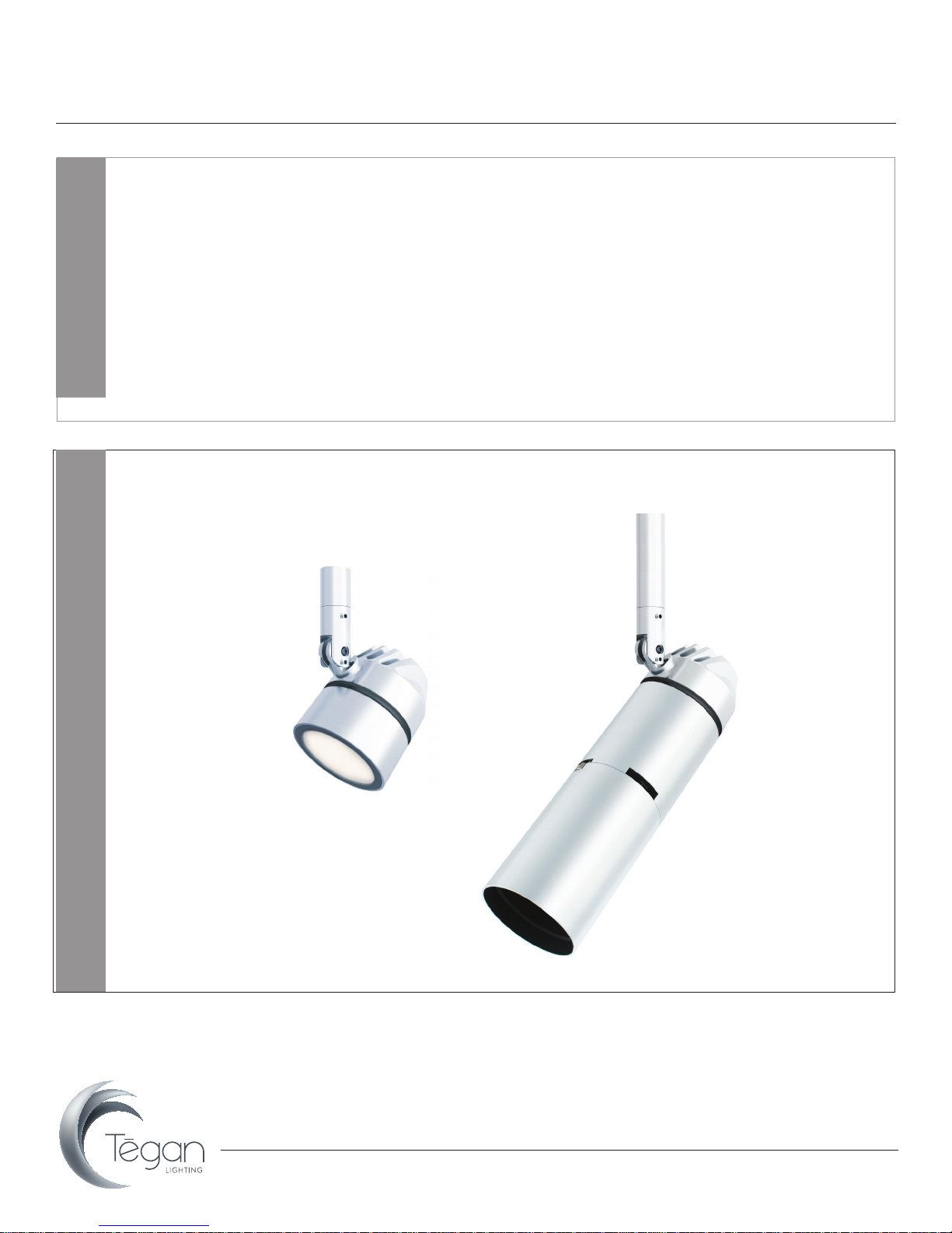
Short Glare Shield (SGS)
Tegan Trac
Installation Instructions
Gobo/Framing Projector (GFP)
Oculus Overview
Note: Refer to separate Gobo/Framing Projector Installation Instructions for additional details.
www.teganlighting.com
•
•
415-504-3536 TG-INS-09a
1
Page 2
OCULUS LED Spotlight
Tegan Trac
Installation Instructions
vaa
1. 2.
HOT
3.
Oculus Installation
Oculus Media Holder 2 -16
Media
(OMH2-16)
Oculus Media Holder 2 -16
Retaining Clip
(OMH2-16)
Oculus Glare Shield
Oculus Media Holder 2 -16
(OMH2-16)
CLICK
4. 5.
Horizontal
Adjustment
Adjustment
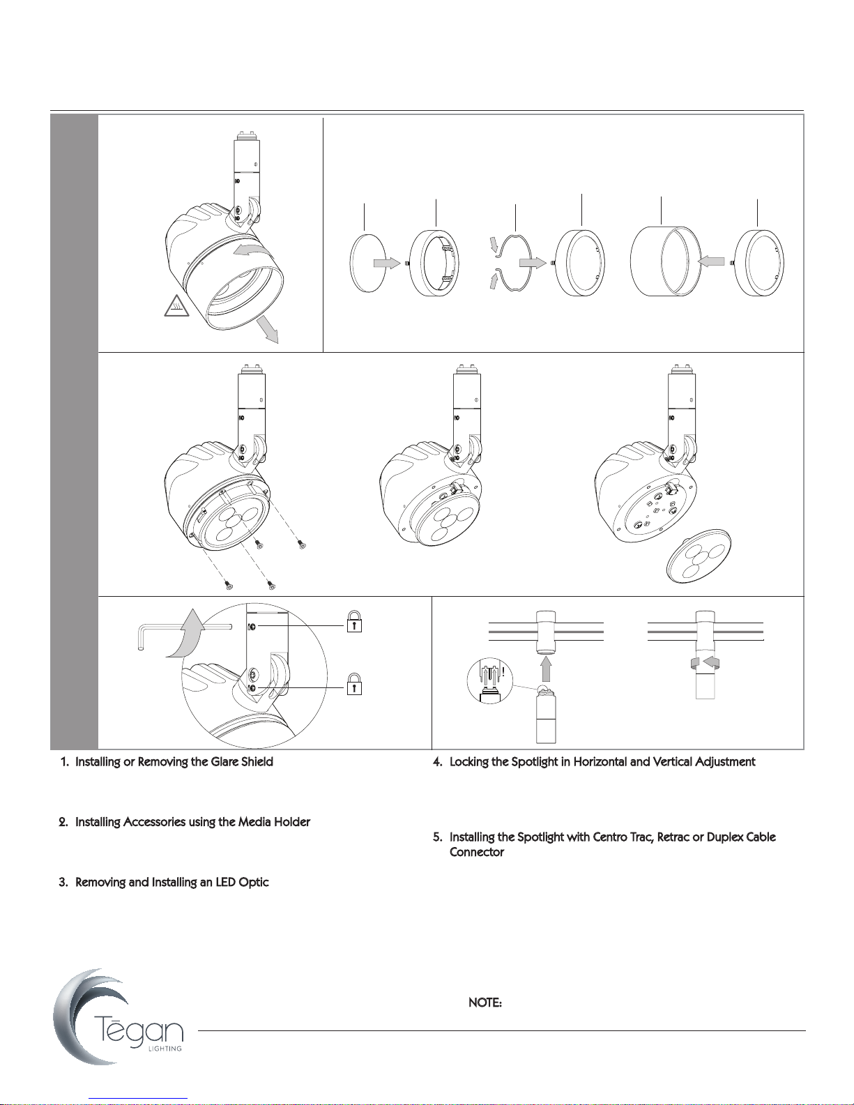
1. Installing or Removing the Glare Shield
• Twist glare shield counter clockwise and remove.
• To reattach glare shield, align indicators as shown and twist
clockwise until you hear a “click.”
2. Installing Accessories using the Media Holder
• Fit up to 2 accessories into Media Holder.
• Secure accessories in place using retaining clip.
• Insert Media Holder into glare shield until it “clicks” into place.
3. Removing and Installing an LED Optic
• Remove the 4 hex screws from the bayonet mechanism.
• Carefully remove the blacok bayonet to expose the optic and install an alternative optic. Line up the optic’s “pegs” with indents
on LED board.
• Replace the bayonet, insert 4 hex screws and tighten.
PAN
Ver tical
TILT
4. Locking the Spotlight in Horizontal and Vertical Adjustment
• Adjust Spotlight to desired position, using angle gauge if
required.
• Lock spotlight position using Allen key provided.
• NOTE: Only adjust position when unlocked.
5. Installing the Spotlight with Centro Trac, Retrac or Duplex Cable
Connector
• Insert Centro Trac, Retrac, or Duplex Cable Connector into Trac
System, ensuring locking screws are aligned (Centro Trac shown
in diagram; refer to specific System Installation Sheets for
details). No connector is required for Monopoints.
• Rotate connector collar until spotlight is securely fastened.
• The Spotlight connects to the Connector with the Twist & Click
mechanism. The Spotlight “clicks” into the the jack plug socket,
then twists into position to lock the connection in place.
NOTE: Do not exceed maximum number of Spotlights per
driver wattage rating, doing so will damage system.
www.teganlighting.com
•
•
415-504-3536 TG-INS-09a
2
 Loading...