

Page 1
10 TEGAM WAY • GENEVA, OHIO 44041 • 440-466-6100 • FAX 440-466-6110
• sales@tegam.com
R1L-D1
HIGH ACCURACY MICROOHMMETER
AND RTD MONITOR
MODEL R1L-D1
Operation and Maintenance Manual
PN# R1L-D1-900-01
Publication Date: March 2017
REV. H
Applies to s e rial number s 10100 and above for units purchased under U.S. Government contract, and serial numbers
2010114R1L-D1 and above for all other units. This manual supersedes all revisions of Operation and Maintenance Manual
(Commercial Version), PN R1L-D1-900-02.
REPRODUCTION AND DISTRIBUTION OF THIS TECHNICAL MANUAL IS AUTHORIZED FOR US GOVERNMENT PURPOSES ONLY.
NOTE: This User’s Manual was as current as possible when this product was manufactured. However,
products are constantly being updated and improved. To ensure you have the latest documentation,
please refer to www.tegam.com.
Page 2

10 TEGAM WAY • GENEVA, OHIO 44041 • 440-466-6100 • FAX 440-466-6110
• sales@tegam.com
R1L-D1
(Inside of Cover, intentionally blank)
Page 3

10 TEGAM WAY • GENEVA, OHIO 44041 • 440-466-6100 • FAX 440-466-6110
• sales@tegam.com
TABLE OF CONTENTS
TABLE OF CONTENTS
1. INSTRUMENT DESCRIPTION
Purpose ............................................................... 1-1
Performance Characteristics ................................... 1-1
Table 1: Ranges ...............................................1-1
Table 2: Specifications ......................................1-1
Description of Equipment ....................................... 1-3
Figure 1: Front Panel Layout ............................... 1-6
List of Items Furnished .......................................... 1-7
Tools & Test Equipment Required for Maintenance ..... 1-7
Storage and Shipping Requirements ........................ 1-7
2. PREPARATION FOR USE AND INSTALLATION
Unpacking and Inspection ...................................... 2-1
Preparation for Use................................................ 2-1
3. OPERATI NG INSTRUCTIONS
Pushbutton Functions ............................................ 3-1
2, 3, and 4-Wire Operation ..................................... 3-3
4. MAINTENANCE
Inspection ............................................................ 4-1
Cleaning .............................................................. 4-1
Test Equipment required for Calibration and Repair ... 4-1
Performance Verification ........................................ 4-2
Calibration ........................................................... 4-4
Troubleshooting .................................................... 4-8
Table 3: Fault Symptoms and Repair Actions ........ 4-9
Preparation for Shipment ..................................... 4-11
Overhaul Inst ructions .......................................... 4-11
Figure 2: Assembly Drawing ............................. 4-13
Figure 3: Battery Assembly Drawing .................. 4-14
Figure 4: Main Board Parts Layout ..................... 4-15
5. SERVICE INFORMATION
Preparation for Repair or Calibration Service ............. 5-1
Expedite Repair and Calibration Form ...................... 5-2
Warranty .............................................................. 5-3
Page 4
10 TEGAM WAY • GENEVA, OHIO 44041 • 440-466-6100 • FAX 440-466-6110
• sales@tegam.com
1-1
INSTRUMENT DESCRIPTION
SECTION 1
INSTRUMENT DESCRIPTION
INTRODUCTION
1.1 Purpose
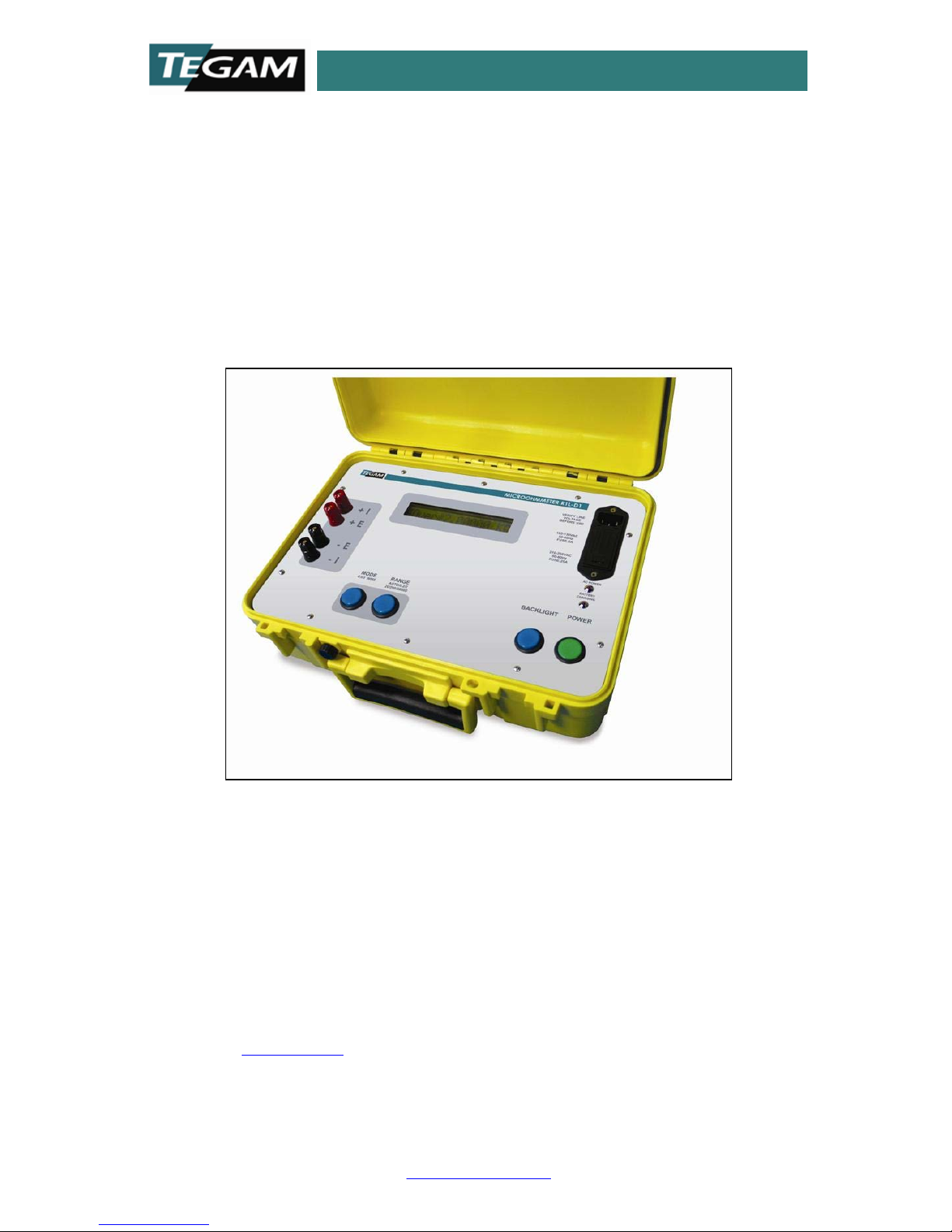
The Model R1L-D1 is a portable microohmmeter designed to
measure low resistances and resistance temperature detectors
(RTD's) with high accuracy. Normally, 4-wire measurements
are utilized in order to eliminate any errors caused by the
lead resistance. Additionally, 2 or 3-wire m easu rements may
be made. Two leads are used to pass a regulated current
through the resistance under test in series with an internal
precisi on calibrat ed resistor. T wo separate l eads are us ed to
measure the voltage drop across the external resistor; this
voltage is then compared with the voltage drop across the
internal resistor. The value of the external resistor is then
calculated from the ratio of these two voltage readings. A
microprocessor, with TEGAM proprietary firmware functions,
performs all calculations such as range selection, display
information etc.
1.2 Performance Characteristics
This is an automatic range-selection instrument, wi th manual
over-ride of one range step.
Range
Full
Scale (Ω)
Resolution
(Ω)
Test Current
Peak (mA)
1
0.199999
1 µ
50
2
1.99999
10 µ
50
3
19.9999
100 µ
50
4
199.999
1 m
0.5
5
1999.99
10 m
0.5
Table 1: Ranges
Page 5

10 TEGAM WAY • GENEVA, OHIO 44041 • 440-466-6100 • FAX 440-466-6110
• sales@tegam.com
1-2
INSTRUMENT DESCRIPTION
Accuracy:
Accuracy of all resistance measurements are affected by the
test leads unless 4-wire Kelvin measurement connections a re
used.
Range
Full
Scale
(Ω)
4-Wire
Kelvin
3-Wire
2-Wire
Test
Current
1
0.199999
±0.05%
±15 LSD*
Not
Specified
Not
Specified
50 mA
2
1.99999
±0.05%
±2 LSD*
Not
Specified
Not
Specified
50 mA
3
19.9999
±0.05%
±1 LSD*
Not
Specified
Not
Specified
50 mA
4
199.999
±0.05%
±1 LSD*
±0.05%
±1 LSD*
±0.05%
±1 LSD*1
0.5 mA
5
1999.99
±0.05%
±1 LSD*
±0.05%
±1 LSD*
±0.05%
±1 LSD*1
0.5 mA
*LSD= Least Significant Digit
1
Does not include test lead or contact resistance
Table 2: Specifications
When making low resistance measurements, variables such
as test lead resistance, contact resistance of all the
connections, as well as ambient temperature will affect the
measurement accuracy. When using 4-wire connections,
these effects are minimized.
When making 2 and 3-wire measurem ent s, ev en if all the t est
leads are of known value, the variables of temperature and
contact resistance remain unpredictable and will add to the
uncertai nty of the mea surement. Th e R1L-D1 accuracy is not
specified for 2 and 3-wire mode on ranges 1 t o 3. This does
not mean that the R1L-D1 cannot be operated in these
ranges, but the user needs to be aware of the issues and
compensate for the variables that affect measurement
accuracy outside of the instrument. Errors that can be
introduced at these resistance levels will likely result in
measurement accuracies beyond t he intrinsic accuracy o f the
R1L-D1. Therefore the accuracy specification is not given.
3-wire operation balances the resistance of one lead against a
second l ead, compensati ng for the lead resi stance as long as
the leads are identical. Therefore in 3-wire mode, the test
leads and their connections must be of identical resistance
Page 6

10 TEGAM WAY • GENEVA, OHIO 44041 • 440-466-6100 • FAX 440-466-6110
• sales@tegam.com
1-3
INSTRUMENT DESCRIPTION
and composition or the measurement accuracy will be
negatively affected.
Operating an ohmmeter with two wires results in lead
resistance, which is in series with the resistor under test,
being added to the unknown resistance. Further, copper wire
resistance has a large temperature coefficient. Two leads of
relatively heavy 18 gauge wire, each 8 feet long, will add
approximately 0.1 Ω to the measured value. Therefore, 2-
wire operation should not be used with low-value resistors,
without subtracting the resistance of the test leads.
Note that the R1L-D1 is a 5 ½ digit instrument in order to
provide 10 mΩ resolution when reading 1060 Ω RTD's. On
lower ran ges, t his provid es fin er res olu tion, down t o 1 µΩ on
the 0.1 Ω range. However, with a maximum of 50 mA of test
current, the voltage signal for 1 µΩ is only 0.05 µV, easily
obscured by noise picked up in the leads. Thus, it should not
be expected to read one count accurately on the low
resistance ranges
.
This uni t will operate ov er a temp eratur e rang e from 0 t o 50
°C. This unit will comply with the requirements of MIL-PRF28800 Class 3 for shipboard applications.
1.3 Description of Equipment
Physical: A rugged heavy-duty case is provided to contain
and protect the instrument. When closed, a gasket seals the
lid to protect the instrument against water and dirt while the
instru ment is carried th rough rainstorm s or other haz ardous
conditions. When the lid is open, for operation of the
instrument, a second gasket provides additional, although
reduced, protection. Feet are molded into the bottom of the
case and projections provide for stacking several units high
during temporary storage.
Dimensions: 356 mm (14”) x 269 mm (11”) x 153 mm (6”).
Weight is 3.6 kg (8 lb). With the lid open for operation, the
front panel and its controls are readily accessible. Controls
Page 7

10 TEGAM WAY • GENEVA, OHIO 44041 • 440-466-6100 • FAX 440-466-6110
• sales@tegam.com
1-4
INSTRUMENT DESCRIPTION
and connectors are of a size and spacing such that the
instrument may be operated while wearing safety gloves.
Electrical: Power is from five rechargeable Ni-Cad C-cells,
rated at 3000 mA-hours each, series-connected. Nominal
voltage is 1.2 V each, totaling 6.0 V. Current drain varies
with range and back-lighting; but is approximately 20 mA
with no connection, providing approximately 140 hours of
operation when fully charged. To charge the battery, check
that the mains input module is set to the correct voltage,
plug the line cord into the front panel AC receptacle, with the
other end connected to a source of AC power. See Section
2.2. The battery will be charged (from a discharged
condition) in less than 8 hours; no damage will occur if
charged for a longer period. Charging power consumption
from nominal AC power line is less than 10 W average. Th is
instrument may be operated while connected to the AC line
without damage.
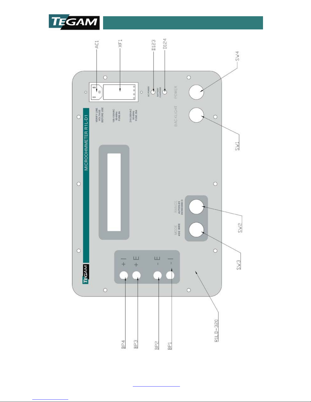
Front Panel Controls and Displays (See Figure 1)
MODE pushbutton
, is used t o select 4-wire, 3-wire, or 2-wire
operati on. When p ower i s first tu rned on, th e default i s to 4wire operation. Successive operations of this pushbutton will
step the unit through 3-wire and 2-wire operation, then back
to 4-wire operation. Note that this is indicated on the display
by a 4, 3, or 2, at the left end of the display.
RANGE pushbutton. Note that the R1L-D1 selec ts the proper
range automatically, but the RANG E pushbutton may be used
to step through all five ranges, plus auto -range, manually.
BACK-LIGHT pus hbutton. One operati on turns the back-light
of the display on. A second operation tur ns the back-light off.
POWER pushbut ton (alternate action). One operation to turn
the pow er on, and a s econd operati on to turn th e power off.
Note that the display may be used as an indication that
power is on.
Page 8

10 TEGAM WAY • GENEVA, OHIO 44041 • 440-466-6100 • FAX 440-466-6110
• sales@tegam.com
1-5
INSTRUMENT DESCRIPTION
DISPLAY is a 16 character alphanumeric back-lit LCD. The
first character, a 2, 3 or 4 indicates 2, 3 or 4-wire
measurement. The next four characters will normally be
"WIRE"; however, they will also read "OVER", if over-range,
or "BATT", for low battery voltage. The sixth character is
either blank or an asterisk, which indicates auto-range. The
next seven characters display the resistance reading (six
digits and the decimal point). Note that while auto-ranging,
this block of characters will read "RANGE". The final
characters (to the right) display the Ω symbol, with the
prefix k or m, as required for kΩ or mΩ.
Note that although the front panel lists the two lowest
ranges as 0.2 and 2 Ω for the sake of simplicity, the display
shows them as 200.000 and 2000.00 mΩ. Also, as is t ypical
of digital voltmeters, full scale readings are rounded off as
2xxx, but actual full-scale readings are 1.99999, etc.
A front panel LED marked "AC POWER" indicates that AC
power is connected.
A front panel LED marked "BATTERY CHARGING" indicates
that the battery is in fast charge mode. If the unit is
connected to AC power and this LED is not on, the Batteries
are in trickle charge mode.
Four binding posts for connection of test leads are marked
+I, +E, -E, and -I. Proper connections to the resistor under
test are described in Section 2.2 below.
Page 9
10 TEGAM WAY • GENEVA, OHIO 44041 • 440-466-6100 • FAX 440-466-6110
• sales@tegam.com
1-6
INSTRUMENT DESCRIPTION
Figure 1: Front Panel Layout
Page 10

10 TEGAM WAY • GENEVA, OHIO 44041 • 440-466-6100 • FAX 440-466-6110
• sales@tegam.com
1-7
INSTRUMENT DESCRIPTION
1.4 List of Items Furnished
1 each Model R1L-D1 with power cord
5 each NiCad battery cells.
1 each Instruction Manual.
1.5 Tools and Test Equipment Required for Maintenance
Solderi ng iron , solder, Phillips No. 1 & 2 screwdriver and
a small flat-bladed screwdriver.
Test equipment: See Section 4.3 below.
1.6 Storage and Shipping Requirements
The R1L-D1 should be stored in a relatively dust free
environment.
Temperature: -40 to +71 °C.
Relative humidity: 0 to 100%, non-condensing.
See Section 4.7 below for shipping requirements.
Page 11

10 TEGAM WAY • GENEVA, OHIO 44041 • 440-466-6100 • FAX 440-466-6110
• sales@tegam.com
2-1
PREPARATION FOR USE AND INSTALLATION
SECTION 2
PREPARATION FOR USE AND INSTALLATION
2.1 Unpacki ng an d Inspection
Upon receipt, the R1L-D1 should be carefully unpacked and
removed from the shipping container. Separate the units
from the packing material and inspect both the instrument
and the accessory kit for any external damage.
• If any dents, broken, or loose parts are seen, do not use
the equipment. Notify TEGAM immediately.
2.2 Preparation for Use
• Release th e tw o l at ches wh i ch secu re th e li d of th e Mod el
R1L-D1, and open t h e lid. Since the lid i s w ell gas keted,
it may be difficult to open if there is an appreciable
difference between internal and external air pressure.
• Note that the instrument is shipped with its battery
removed. U nw rap the fi ve N i Cad C -cel l s which comp ri se
the battery.
• Inspect the MAINS power entry module and make sure
that it indicates the proper voltage for the MAINS to be
used (120 or 240 VAC).
MAINS Setup
If the mains voltage is not correct, proceed as follows:
a. Pry the top of the MAINS cover open by inserting a flat
bladed tool at the top of the module just down from the
mains terminals.
b. Remove the fuse assembly and replace the fuse with the
correct one .
For 115 VAC operation: FU-203; Bussman AGC 0.5 A /
Littelfuse 0312.500 (Fast Blow)
For 230 VAC operation: FU-1804-2; Bussman GDC 0.25 A
/ Littelfuse 0218.250 (Slow Blow)
The single 1/4"x1.25" 0.5 A 120 V fu se goes on one side
Page 12

10 TEGAM WAY • GENEVA, OHIO 44041 • 440-466-6100 • FAX 440-466-6110
• sales@tegam.com
2-2
PREPARATION FOR USE AND INSTALLATION
of the fuse holder (the side with the metal jumper), and
the dual 5x20mm fuses get installed on the other side.
c. Pull the voltage selector card from its slot at the bottom
end of the mains entry module and reposition the plastic
indicator for the required mains voltage (120 or 240).
d. Insert th e v ol tag e sel ect or card back into its slot such that
the plastic indicator is at the top of the module assembly.
e. Close the door and note that the indicator pin now
indicates the correct mains voltage. If it is not indicated
properly , then rem ove as i n points a to d and ensure that
the proper voltage is selected.
Battery Installation
Remove the ten screws around the outside edge of the
panel, which secure the instrument to the case. The
instrument may now be lifted out of the case by holding the
binding posts.
WARNING
DO
NOT CONNECT THE AC LINE CORD PRIOR TO
REMOVING THE UNIT FROM ITS CASE OR WHILE THE UNIT
IS OUT OF ITS CASE, OR ELSE THE MAINS VOLTAGE W ILL
PRESENT A POSSIBLE SHOCK H AZ AR D.
CAUTION
DO NOT OPERATE THIS INSTRUMENT WITHOUT ITS
INTERNAL BATTERY.
Remove the four screws holding the battery cover to its
mounting spacers and install the five C-cells in their holder
at the bottom of the instrument; be sure to install them
with the correct polarity, as marked on the holder. While
installing the cells, rotate them li ghtly to ensure connection
to the holder contacts.
After installing the cells, reinstall the battery cover with its
four screws, and reinstall the instrument in its case and
secure the ten mounting screws.
Page 13

10 TEGAM WAY • GENEVA, OHIO 44041 • 440-466-6100 • FAX 440-466-6110
• sales@tegam.com
2-3
PREPARATION FOR USE AND INSTALLATION
To charge the battery before use, use the power cord
appropriate for the mains (120 VAC cord supplied). Allow
approximately 8 hours for a full charge; the “BATTERY
CHARGING” LED will turn off when the battery is fully
charged. After charging, remove the power line cord,
although no harm will result if it is left plugged in. Note that
with a fully discharged battery, the charger may turn off after
a few minutes (because the rapid increase in voltage could
be inter preted a s the fu lly cha rged con dition ). If th at occurs ,
unplu g the power cord briefl y and then plug it in again; the
unit should now charge for several hours.
WARNING
ALTHOUGH THE FRONT PANEL IS NORMALLY GROUNDED
VIA THE GROUND PIN OF THE POWER CABLE, IF THIS
CONNECTION IS F AULTY AND IF THE HIGH SIDE OF THE
POWER CABLE IS SHORTED TO THE PANEL
, THE PANEL
COULD POSSIBLY HAVE MAINS VOLTAGE ON IT
; SO DO
NOT TOUCH THE PANEL WHEN AC POWER IS
CONNECTED.
Connection to Resistor under Test
Connect the resistor under test to the 4 front-panel binding
posts as follow s:
For
4-wire operation, connect the +I and +E binding
posts to one end of the resistor under test and -I and -E t o
the other end of the resistor under test.
For
3-wire operation, connect +I and + E to one si d e of the
3-wire RTD a nd conn ect –I to th e othe r side o f the RTD . –E
is not connected.
For 2-
wire operation, use +I and –I, +E and –E are not
connected.
WARNING
DO NOT TOUCH THE BINDING POSTS WHEN THEY ARE
CONNECTED TO EXTERNAL CIRCUITS. LETHAL
VOLTAGES MAY BE PRESENT AT THESE PO STS.
Page 14

10 TEGAM WAY • GENEVA, OHIO 44041 • 440-466-6100 • FAX 440-466-6110
• sales@tegam.com
3-1
OPERATING INSTRUCTIONS
SECTION 3
OPERATING INSTRUCTIONS
The R1L-D1 is de signed for bench-top or field operation. Use
the cables (available from TEGAM), connecting their banana
plug terminations to the four binding posts marked +I, +E, E, and -I. Set the shorting bar so that it does NOT connect -I
to -E, unless you plan to make 2 or 3-terminal
measurements. Note that the test current is actually AC, and
the + and - indications are used only to signify HIGH and
LOW, as well as to indicate that the +E and +I go together
and the -E and -I go together.
3.1 Pushbutton Functions
Operation of the Model R1L-D1 is essentially automatic and
extremely simple. There are only four pushbuttons, three
momentary and one latching.
The MODE pushbutton selects 4-wire, 3-wire, or 2-wire
operation. When power is turned on, it defaults to 4-wire
operation. S uccessive operations of this pushbutton will step
the unit through 3-wire and 2-wire operation, then back to
4-wire operation. Note that this is indicated by a 4, 3, or 2 at
the left end of the display.
The RANGE pushbutton will manually scroll through the five
ranges and auto-range. Default condition when power is
turned on is Auto-range. In Auto-range, the R1L-D1
automatically steps thru the ranges until the displayed signal
is between 20,000 and 199,999 counts. An asterisk in the
sixth character of the display indicates auto-ranging.
Full scale on any range may be described as 200,000
(actually 199,999), since this is a 5 ½ digit meter. I f th e un it
sees readings exceeding 199,999 counts, it will automatically
step to the next higher range. If it sees readings less than
20,000 counts, it automatically steps down a range, so that
Page 15

10 TEGAM WAY • GENEVA, OHIO 44041 • 440-466-6100 • FAX 440-466-6110
• sales@tegam.com
3-2
OPERATING INSTRUCTIONS
it will read 199,999 counts, or less. The decimal point is
located automatically for the correct reading.
Thus, it is not necessary to use the RANGE pushbutton.
Howeve r, if a sp ecific ra n g e is desired for a ny reas on , depress
the RANGE pushbutton several times to step through the five
ranges. The first step after Auto-range is the 0.2 Ω range;
each step following is to a higher range, as seen on the
display. After the 2 k range, th e next step i s to Auto-Range,
again. If the selected range is too low for the value of the
resistor under test, the display will show over-range.
Note that if a resistor val ue is very close to 20 0,000 counts,
the unit may cycle between 199,999 on one range and
20,000 counts on the next lower range. If that should occur,
use manual ranging and set it to the lower range reading
20,000 counts.
The BACK-LIGHT pushbutton turns on the back-light behind
the display, to be used only in dim light, because it does
increas e the drai n on th e batter y. The ba ck-light will stay on
until turned off by a second op e ra t ion of t he back-light switch
or until power is turned off. When power is turned on, the
default condition is back-light off.
The POWER pushbutton turns on the power to operate the
unit. This is an “alternate-action” (latching) pushbutton; a
second operation turns the power off. The appearance of the
display will show that power is on; absence of the display
indica t es t h at ei t h er p o wer is off, bat t e ries are discharged, o r
there is so me malfunction . Note that when p ower is turned
off, it m ay take s everal s econds t o discharg e ci rcuit capa city
to completely blank the display. The black markings seen
have no effect and disappear when power is turned back on.
CAUTION
DO NOT USE EXCESSIVE FORCE TO OPER ATE ANY OF THE
PUSHBUTTONS. POWER OFF DOES NOT OCCUR UNTIL
BUTTON IS RELEASED.
Page 16

10 TEGAM WAY • GENEVA, OHIO 44041 • 440-466-6100 • FAX 440-466-6110
• sales@tegam.com
3-3
OPERATING INSTRUCTIONS
3.2 2, 3, and 4-Wire Operation
See Section 2.2 for connection instructions.
Operating an ohmmeter with two wires results in the lead
resistance, which is in series with the resistor under test,
being added to the unknown resistance. Two leads of
relati vely heavy 18 g a uge wire , each 8 feet long, will add 0.1
Ω to the measured value. Obviously, 2-wire measurement
should not be used with low-value resistors, without
subtracting the resistance of the test leads. Accuracy is
reduced with 2 or 3-wire operation.
3-wire measurement balances the resistance of one lead
against a second lead, compensating for the lead resistance
if the leads are identical. It is better than 2-wire
measurement, but not as good as 4-wire.
4-wire measurement uses two leads to deliver (and return)
the test current to the resistor under test. The two voltage
leads ar e then u sed to m easu re the I x R d rop di rectl y a t t he
unknown resistor. This is the most accurate method of
measuring small values of resistance.
Page 17

10 TEGAM WAY • GENEVA, OHIO 44041 • 440-466-6100 • FAX 440-466-6110
• sales@tegam.com
4-1
MAINTENANCE
SECTION 4
MAINTENANCE
4.1 Inspection
These units should be inspected semi-annually. Check that
the case opens and closes with no binding. Check that the
four pushbuttons rate smoothly. Check all four binding posts
to ensure that they operate smoothly.
4.2 Cleaning
The instrument should be cleaned periodically, as is
necessary, using mild soap and a damp cloth both on the
outside of the case and on the front panel. No lubrication is
required.
4.3 Test Equipment Required for Calibration and Repair
Calibration of the R1L-D1 is recommended on a yearly
basis, and is done at a temperature of 23 ± 1 °C.
A computer with RS-232 interface and with terminal
emulation software such as HyperTerminal.
Precisi on d eca d e r esistance b ox co v e ring the ra n g e f rom 0.1
Ω to 1.06 k, such as a PPM, Inc., Model R6-111.111K, or
equal. Required accuracy is ± 0.01% of setting + 0.002 Ω.
*For equivalent R1L-D1 calibrator box use the following
resistors:
Calibrat or pos ition nomin al resistance
1 0.100000
3 1.000000
5 10.00000
7 100.0000
9 1000.000
Page 18

10 TEGAM WAY • GENEVA, OHIO 44041 • 440-466-6100 • FAX 440-466-6110
• sales@tegam.com
4-2
MAINTENANCE
A standard digital voltmeter (accuracy of 0.01% of reading,
or better) and an oscilloscope (bandwidth of 50 MHz, or
more). Suggested voltmeter is a Keithley Model 2000;
suggested Tektronix oscilloscope Model TDS 360.
Variable 4-7 V DC Power Supply, at 1.0 A min.
Thin Nylon Battery Terminal Insulat i ng S t rip
4.4 Performance Verification
1. Connect the four binding posts to the precision decade
resistor box. For 4-wire hook-up, use banana plugs to
connect the +I lead t o the top of the "High" bindi ng post
and -I to the top of the "Low" binding post. Use spade
lugs to connect the +E lead to the bottom of the "High"
binding post and -E to the bottom of the "Low" binding
post.
2. The Mod el R1 L-D1 should default to 4-wire me asuremen t
and auto-ranging when turned on. For measurements of
all five ranges listed below, check readings via autoranging, and then repeat after stepping through the
manual ranges, to ensure proper operation with either
Auto-range or manual range selection.
3. Set the r esistor box to 1060 Ω and operate the R1L-D1.
Check that the R1L-D1 reads between the resistor box
1060 Ω setting’s actual value ± 0.54 Ω in Auto-Range
(default condition when power is turned on). Then step
through the ranges to the 2 k manual range and check
that the R1L-D1 reads between the resistor box 1060 Ω
setting’s actual value ± 0.54 Ω.
4. Set the resistor box to 100 Ω and operate the R1L-D1.
Check that the R1L-D1 reads between the resistor box
100 Ω setting’s actual value ± 0.051 Ω in Auto-range.
Then step th rough the ranges to the 200 Ω manual range
and check that the R1L-D1 reads between the resistor
box 100 Ω setting’s actual value ± 0.051 Ω.
Page 19

10 TEGAM WAY • GENEVA, OHIO 44041 • 440-466-6100 • FAX 440-466-6110
• sales@tegam.com
4-3
MAINTENANCE
5. Set the resistor box to 10 Ω and operate the R1L-D1.
Check that the R1L-D1 reads between t h e r esistor box 1 0
Ω setting’s actual value ± 0.0051 Ω in Auto-range. Th en
step through the ranges to the 20 Ω manual range and
check that the R1L-D1 reads betw een th e re sis tor box 10
Ω setting’s actual value ± 0.0051 Ω.
6. Set the resistor box to 1 Ω and operate the R1L-D1.
Check that the R1L-D1 read s between th e resistor b ox 1
Ω setting’s actual value ± 0.52 mΩ in Auto-range. Then
step through the ranges to the 2 Ω manual range and
check that the R1L-D1 reads betw een the resistor box 1
Ω setting’s actual value ± 0.52 mΩ.
7. Set the resistor box to 0.1 Ω and operate the R1L-D1.
Check that the R1L-D1 reads between the resistor box
0.1 Ω setting’s actual value ± 0.065 mΩ in Auto-range.
Then step through the ranges to the 0.2 Ω manual range
and check that the R1L-D1 reads between the resistor
box 0.1 Ω setting’s actual value ± 0.065 mΩ.
8. To check 3-wire operation, disconnect the wire between
the -E binding post and the resistor under test. Repeat
the tests listed in 4.4.3 and 4.4.4. Note that the accuracy
will be degraded if the lead from the +E binding post and
the +I lead do not have exactly the same resistance.
Other ranges are not specified.
9. To check 2-wire op eration, di sconnect t he wires b etween
the +E binding post and the resistor under test. (This
leaves on ly +I and –I wires con nected). Repeat the tests
listed in 4.4.3 and 4.4.4. Note that the accuracy will be
degraded by the resistance of the leads. Other ranges are
not specified.
Page 20

10 TEGAM WAY • GENEVA, OHIO 44041 • 440-466-6100 • FAX 440-466-6110
• sales@tegam.com
4-4
MAINTENANCE
4.5 Calibration
CAUTION
DANGEROUS VOLTAGES ARE P RESENT DURING PARTS
OF THIS PROCEDURE.
1. If the R1L-D1 rechargeable battery cells have not been
previously charged, or are low on charge, connect the
R1L-D1 AC line cord and allow a charge time of at least
one-half hour. The R1L-D1 "Battery Charging
"
LED (as
well as "AC Power" LED) should illuminate. Note: If the
R1L-D1 battery cells are being ch arged for the first t ime
or are heavily discharged, the R1L-D1 may switch into
trickle charge ("Battery Charging" LED goes out) during
the first fifteen minutes. If this happens, unplug the AC
line cord and then reconnect it. The "Battery Charging"
LED should re -illumina te and stay ON.
2. Unplug the AC line cord from the R1L-D1 front panel.
Connect the Resistance Box to the R1L-D1. Connect the
10 Ω standard using 4-wire c onn ect i on. R em ove t h e R1 L-
D1 front panel from the yellow case and turn it upside
down. Connect the AC line cord.
3. Confirm the "Charging
"
LED is illu minated. Set the Digital
Multimeter to read DC volts, and connect its negative
lead to TP 104 (Circuit Ground). Connect the positive
Multimeter lead to TP 103. Verify a voltage reading
between +0.25 and +0.27 V. Disconnect the R1L-D1 AC
line cord.
4. Move the positive Multimeter lead to TP105 and turn the
R1L-D1 Power Switch ON. Verify a voltage reading
between +4.8 and +5.2 V.
5. Move the positive Mul timeter lead to TP106 and verify a
voltage reading between +4.8 and + 5 .2 V.
6. Turn the R1L-D1 OFF. Insert the Nylon Insulator Strip
between one of the R1L-D1 battery cell's negative end
Page 21

10 TEGAM WAY • GENEVA, OHIO 44041 • 440-466-6100 • FAX 440-466-6110
• sales@tegam.com
4-5
MAINTENANCE
and its battery holder terminal to disconnect battery
power. Connect the negative l ead from the Mul timeter t o
TP103, and the positive lead from the Multimeter to TP102
(shoul d read less th an 3 V). Adjust the Variable DC Power
Supply for 7.0 ± 0.1 V and turn it OFF.
OBSERVING
PROPER POLARITY
, connect the negative DC Power
Supply lead to TP103 and the positive lead to TP102.
Carefully orient the R1L-D1 front panel so you can
observe its LCD readout. Turn ON the DC Power Supply
and turn ON the RIL-D.
7. Adjust the DC Power Supply voltage downward, and
verify the R1L-D1 LCD reading does not vary by more
than ± 1 count as the voltage is turned down to where
"BATT", indicating low battery voltage is displayed on the
LCD. Also verify "BATT" appears at a Power Supply
voltage of 5.35 ± 0.1 V.
8. Turn the R1L-D1 OFF. Disconnect the DC Power Supply
and Multimeter leads. Connect the serial cable from the
personal computer (PC) to the R1L-D1, open
HyperTerminal and setup the RS-232 parameters with
following setting. Rest the R1L-D1 front panel in its
proper orientat io n in it s yellow case.
Step 1: Enter a
name such as
‘R1L-D1’.
Page 22

10 TEGAM WAY • GENEVA, OHIO 44041 • 440-466-6100 • FAX 440-466-6110
• sales@tegam.com
4-6
MAINTENANCE
9. Connect the 1 Ω standard and turn ON the R1L-D1.
Confirm t he R1L-D1 a utoma ticall y goes to th e 2 Ω range,
and indi cates 4-wire, an asterisk for auto-range, and the
resistance. Resistance values should also appear on the
PC screen.
10. Type a lower case "r" and ENTER on the PC keyboard.
Verify a temperature sensor reading between 20 and 30
°C on the PC screen.
Step 2: Do not enter
a
phone number.
Use COM port
selectable in the drop
down menu “Connect
using”
Step 3: Enter port
settings shown on
the right.
Page 23

10 TEGAM WAY • GENEVA, OHIO 44041 • 440-466-6100 • FAX 440-466-6110
• sales@tegam.com
4-7
MAINTENANCE
11. Type an upper case "L" followed by 12000 (i.e. L12000)
and ENTER on the PC keyboard for LCD temperature
compensation at 0 °C.
12. Type an upper case "L" followed by 22000 (i.e. L22000)
and ENTER on the PC keyboard for LCD temperature
compensation at +40 °C.
13. Type
"F3"
(not function key) and ENTER on the PC. Verify
a filter setting of 80 mSec on the PC screen.
14. This step and the next will calibrate the five R1L-D1
resistance ranges in 4-wire mode. Each calibration
resistance must be entered as a ten-digit number, with
the last digit being µΩ. Connect the 100 mΩ standard,
and dep ress t he R1 L-D1 "Range" button to place the R1 LD1 in the manual 200 mΩ range. Wait unt il a stabl e set of
readings are displayed on the PC screen. Type "CAL"
followed by the 10 digit calibration number followed by
ENTER on the PC. An example for this range might be
CAL0000099860 followed by ENTER. Wait to observe a
few readings close to the calibration value on the PC
screen.
15. Connect the 1 Ω standard, and depress the R1L-D1
"Range" button to place the R1L-D1 in the 2 Ω range.
Input th e cal ibrat ion val ue as in th e previ ous st ep. Rep eat
this pr ocedure wi th the 10 Ω range, 100 Ω range, and 1
kΩ range.
16. Turn the R1L-D1 OFF, wait 10 seconds, and turn it back
ON. Connect the 1 Ω standard and verify a reading of
within ± 0.00015 Ω of the calibration value. C onnect the
1 kΩ standard, and verify a reading of ± 0.1 Ω of the
calibration value.
17. Disconnect only the -E side of the test leads from the
R1L-D1 terminals (leaving -E open). D epress t he R1L-D1
"Mode" button to place the R1L-D1 in 3-wire mode.
Connect the 1 kΩ standard, and verify a reading of ± 0.4
Ω of the calibration value. Connect the 10 Ω standard,
Page 24

10 TEGAM WAY • GENEVA, OHIO 44041 • 440-466-6100 • FAX 440-466-6110
• sales@tegam.com
4-8
MAINTENANCE
and verify a reading of ± 0.004 Ω of the calibration
value.
18. Di sconnect the +E side of the test leads from the R1L-D1
(leaving connections between the +I and -I terminals).
Depress the R1 L-D1 " Mod e" bu tton to p lac e th e R1 L-D1 in
2-wire mode. Connect the 10 Ω standard, and verify a
reading of ± 0.1 Ω of the ca l ibration va lue. Connect the 1
kΩ standard, and verify a reading of ± 0.4 Ω of the
calibration value.
19. Push the R1L-D1 "Backlight" button and verify the
backlight turns ON and OFF.
20. P l ace th e R1L-D1 in 4-wire m ode an d recon n ect th e lea ds
to the 10 Ω standard. Toggle the R1L-D1 backlight ON
and OFF, and verify the displayed reading does not
change by more than ± 1 c ount.
21. Depress the R1L-D1 "Range" button to manually place
the R1L-D1 in the 2 Ω range. Verify the R1L-D1 LCD
indicates "4OVER 2000 mΩ".
22. At a convenient time, fully charge the R1L-D1 battery
cells by connecting the AC line cord to the R1L-D1. Leave
the R1L-D1 switched OFF. The R1L-D1 battery cells
should be fully charged within approximately 8 hours
after AC power is applied.
4.6 Troubleshooting
Test with the precision decade resistance box, if the unit
fails to perform in accordance with these tests, repair
and/or calibration is required. First recalibrate, as described.
If the unit still fails to perform, repair is required.
Check voltages at the following test points (all voltages are
read with respect to TP104 (common). Location of these
test point is indicated on the Par ts L ayout drawing, Figure 4.
Page 25

10 TEGAM WAY • GENEVA, OHIO 44041 • 440-466-6100 • FAX 440-466-6110
• sales@tegam.com
4-9
MAINTENANCE
TP101: Nominal +9 V ± 10%.
TP102: Nominal +7.5 V min with battery fully charged.
TP103: Nominal +0.22 V min when charging dead battery.
TP105: Nominal +5 V ± 5%.
TP106: Nominal +5 V ± 5%.
TP201: 2.45 MHz sine wave, minimum 1 V p-p (± 10%).
TP301: ± 8 V min pulsed (RS-232 Transmitted Data).
TP302: ± 8 V min pulsed (RS-232 Received Data).
TP303: 0 to 5 V ± 5% pulsed (RS-232 Transmitted Data).
TP304: 0 to 5 V ± 5% pulsed (RS-232 Received Data).
TP701: Nominal +2.5 V ± 10%.
Circuit tracing should start with the power supply and check
of all power voltages at the test points listed above. If the
display fun ctions norm ally, bu t resistance reading s are very
low or over-range, check test point TP701 which indicates
proper test current to the external resistor. Continue with
the next section.
Assembly
After removal of the instrument from its case, the basic
instrument consists of a front panel assembly, a main
printed-circuit board assembly with a display, plugged into
and bolted to the main circuit board assembly, and the
battery assembly. See the R1L-D Assembly Drawing in
Figure 2.
Disassembly
See the il lustrati on in Figure 2. To di sa ssem b le, first remove
the nine screws holding the main circuit board assembly to
the front panel spacers. To remove the display from the
main circuit board assembly, remove the two screws at
each end of the display and carefully unplug the display
from the main board . Four scr ews secure th e battery c over
plate; these must be removed to replace the battery. All
integrated-circuits, including the microprocessor and the AD converter, are plugged into sockets and may be removed
easily, with no need for unsoldering. Other components,
such as resistors, capacitors, etc., must be unsoldered for
removal.
Page 26

10 TEGAM WAY • GENEVA, OHIO 44041 • 440-466-6100 • FAX 440-466-6110
• sales@tegam.com
4-10
MAINTENANCE
Re-assembly
After trouble-shooting and repair, re-assemble all parts in
reverse order from above. Do not tighten the screws until
all hav e been i nstal led , to en sure th at al l pa rts are cen tered
properly. Check that all three cable connectors are secured.
Following are possible symptoms, diagnosis, and repair
suggestions for use in trouble-shooting (the most likely
causes are listed first).
Symptom Faulty Compone nt Repair
No display
Battery needs cha r ge
Battery con nection
R801
Display
U101
U111
Loose cable connector
U201
Y201
Charge battery.
Check all f ive cells.
Adjust, replace if bad.
Replace display.
Check for +5 V at Pin 2. If
not, replace U101.
Check for +5 V at Pin 2. If
not replace U111.
Tighten connector.
Check J801-5 for a ctivity,
if none replace U201.
If no 2.45 MHz signal at
TP201, replace Y201.
Battery
won’t
charge
U120
Q121
D121, D122, or D123
T121
R122
B101-B105
Replace U120.
Replace Q121.
Replace D121, D122, D125
Replace T121.
Replace R122.
Replace B101-B105.
Ranges 1-3
faulty
Q701
R704
Replace Q701.
Replace R704.
Ranges 4-5
faulty
Q701
Replace Q701.
Faulty
readings
U700
J701
Q702 or Q703
U702
Replace U700.
Check conn e c tion at
binding posts.
Replace Q702 or Q703.
Check TP701, replace U702
if no voltage present.
Table 3: Fault Symptoms and Repair Actions
Page 27

10 TEGAM WAY • GENEVA, OHIO 44041 • 440-466-6100 • FAX 440-466-6110
• sales@tegam.com
4-11
MAINTENANCE
After trouble-shooting and repair, the instrument must be
recalibrated in accordance with 4.5 above.
4.7 Preparation for Shipment
The original shipping carton is not reusable.
The unit should be repackaged in a humidity-sealed carton
in accordance with MIL-P-116J, which is the specification
governing covering and preservation used in the initial
shipment from the manufacturer.
The Model R1L-D1 is a rugged instrument and requires no
special covering, preservation or speci al cradles. Packaging
must prov id e suf fi ci ent re sil i ent m ateri a l , in accorda nc e wi th
standard packaging practices, to prevent excessive shock to
the power supply and display during shipment.
4.8 Overhaul Instructions
The M odel R1L-D1 is an all solid-state unit and requires no
periodic overhaul, other than routine cleaning and
inspection, as listed in Sections 4.1 and 4.2 and circuit
calibration, described under Section 4.5 above.
However, some disassembly is required to remove and to
install the battery. Disassembly instructions may be found
under Sections 2 and 4.6 above. Re-assembly instructions
are listed in Section 4.6 as well.
Tools required are l isted in Section 1.6 and test equipment
required is listed in Section 4.3.
Trouble-shooting is listed in Section 4.6.
The only component expected to requ ire repl acement i s the
battery. Battery designation is listed in the Replacement
Parts List, and installation instructions are listed in Section
2.1.
Page 28

10 TEGAM WAY • GENEVA, OHIO 44041 • 440-466-6100 • FAX 440-466-6110
• sales@tegam.com
4-12
MAINTENANCE
A fully charged battery should power the R1L-D1 for
approximately 140 hours continuously, without connection
to an external resistor and without the backlight on.
Operation on any of the three lowest resistor ranges will
reduce this to approximately 24 hours, and operation with
the backlight on will reduce this to approximately 20 hours.
The battery may be discharged and recharged at least 100
completed cy cl es b efor e r equ i ri ng rep l acemen t. Note that, it
is recommended that NiCad batteries be completely
discharged before recharging or their effective capacity is
reduced.
Page 29

10 TEGAM WAY • GENEVA, OHIO 44041 • 440-466-6100 • FAX 440-466-6110
• sales@tegam.com
4-13
MAINTENANCE
Figure 2: Assembly Drawing
Page 30

10 TEGAM WAY • GENEVA, OHIO 44041 • 440-466-6100 • FAX 440-466-6110
• sales@tegam.com
4-14
MAINTENANCE
Figure 3: Battery Assembly Drawing
Page 31

10 TEGAM WAY • GENEVA, OHIO 44041 • 440-466-6100 • FAX 440-466-6110
• sales@tegam.com
4-15
MAINTENANCE
Figure 4: Main Board Parts Layout
Page 32

10 TEGAM WAY • GENEVA, OHIO 44041 • 440-466-6100 • FAX 440-466-6110
• sales@tegam.com
5-1
SERVICE INFORMATION
SECTION 5
SERVICE INFORMATION
Preparation for Calibration or Repair Service
Once you have verified that the cause for R1L-D1
malfunction cannot be solved in the field and the need for
repair and calibration service arises, contact TEGAM
customer service to obtain an RMA, (Returned Material
Authorization), number. You can contact TEGAM customer
service via the TEGAM website, www.tegam.com
or by
calling 440.466.6100 (All Locations) OR 800.666.1010
(United States Only).
The RMA number is unique to your instrument and will help
us identify you instrument and to address the particular
service request by you which is assigned to that RMA
number.
Of even importance, a detailed written description of the
problem should be attached to the instrument. Many times
repair turnaround is unnecessarily delayed due to a lack of
repair instructions or of a detailed description of the
problem.
This description should include information such as
measurement range, and other instrument settings, type of
components being tested, are the symptoms intermittent?,
conditions that may cause the symptoms, has anything
changed since the last time the instrument was used?, etc.
Any detailed information provided to our technicians will
assist them in identifying and correcting the problem in the
quickest possible manner. Use a copy of the Repair and
Calibration Service form provided on the next page.
Once this information is prepared and sent with the
instrument to our service department, we will do our part in
making sure that you receive the best possible customer
service and turnaround time possible.
Page 33

10 TEGAM WAY • GENEVA, OHIO 44041 • 440-466-6100 • FAX 440-466-6110
• sales@tegam.com
5-2
SERVICE INFORMATION
Expedite Repair & Calibration Form
Use this form to provide additional repair information and
service instructions. The Completion of this form and
including it with your instrument will expedite the processing
and repair process.
RMA#:
Instrument
Model #:
Serial Number:
Company:
Technical
Contact:
Phone
Number:
Additional
Contact Info:
Repair Instructions:
Evaluation Calibration Only Repair Only
Repair & Calibration Z540
Detailed Sy mpt oms:
Include i nformati on such a s measurem ent ran ge, instru ment
settings, type of components being tested, is the problem
intermittent? When is the problem most frequent?, has
anything changed with the applicati on since the last time the
instrument was used?, etc.
Page 34

10 TEGAM WAY • GENEVA, OHIO 44041 • 440-466-6100 • FAX 440-466-6110
• sales@tegam.com
5-3
SERVICE INFORMATION
Warranty
TEGAM, Inc. warrants this product to be free from def ects in
material and workmanship for a period of three years from
the date of shipment. During this warranty period, if a
product proves to be defective, TEGAM Inc., at its option, w ill
either repair the defective product without charge for parts
and labor, or exchange any product that proves to be
defective.
TEGAM, Inc. warrants the calibration of this product for a
period of one year from date of shipment. During this period,
TEGAM, Inc. will recalibrate any product, which does not
conform to the published accuracy specifications.
In order to exercise this warranty, TEGAM, Inc., must be
notified of the defective product before the expiration of the
warranty period. The customer shall be responsible for
packaging and shipping the product to the designated
TEGAM se rvice cent er wi th shippi ng charges prepaid . TEGAM
Inc. shall pay for the return of the product to the customer if
the shipment is to a l ocation wi thin the country in which the
TEGAM service center is located. The customer shall be
responsible for paying all shipping, duties, taxes, and
additional costs if the product is transported to any other
locati ons. Rep aired produ cts ar e warra nted for t he rem aini ng
balance of the original warranty, or 90 days, whichever
period is longer.
Page 35

10 TEGAM WAY • GENEVA, OHIO 44041 • 440-466-6100 • FAX 440-466-6110
• sales@tegam.com
5-4
SERVICE INFORMATION
Warranty Limitat ions
The TEGAM, Inc. warranty does not apply to defects resulting
from unauthorized modification or misuse of the product or
any part. This warranty does not apply to fuses, batteri es, or
damage to the instrument caused by battery leakage.
The foregoing warranty of TEGAM is in lieu of all other
warranties, expressed or implied. TEGAM specifically
disclaims any implied warranties of m er chan ta bil ity or fi t ness
for a parti cula r purpose . In no even t wil l TEGAM b e lia ble for
special or consequential damages. Purchaser’s sole and
exclusi ve remedy in t he event any i tem fails to comply with
the foreg oing express w arranty of TEGAM shall be to r eturn
the item to TEGAM; shipping charges prepaid and at the
option of TEGAM obtain a replacement item or a refund of
the purchase price.
Statement of Calibration
This instrument has been inspected and tested in accordance
with specifications published by TEGAM Inc. The accuracy
and calibration of this instrument are traceable to the
National Institute of Standards and Technology through
equipment, which is calibrated at planned intervals by
comparison to certified standards maintained in the
laboratori es of TEGAM Inc.
Page 36

10 TEGAM WAY • GENEVA, OHIO 44041 • 440-466-6100 • FAX 440-466-6110
• sales@tegam.com
5-5
SERVICE INFORMATION
Contact Information
TEGAM INC.
10, TEGAM WAY
GENEVA, OHIO 44041
CAGE Code: 49374
WEB: http://www.tegam.com
 Loading...