

Page 1
PS-CAL®
Power Sensor Calibration Software
10 T
EGAM WAY • GENEVA, OHIO 44041 440-466-6100 • FAX 440-466-6110 • www.tegam.com
Instruction Manual
PN# PS-CAL-900
Publication Date: February, 2018
REV. B
Page 2

TEGAM is a manufacturer of electronic test and measurement equipment for metrology, calibration, and
production test. We also provide repair, calibration, and other support services for a wide variety of test
and measurement equipment including RF power sensor calibration systems, RF attenuation measurement
systems, ratio transformers, arbitrary waveform generators, micro-ohmmeters, LCR meters, handheld
temperature calibrators, thermometers, humidity and temperature control devices, and more.
TEGAM also repairs and calibrates test and measurement equipment formerly manufactured by ElectroScientific Industries (ESI), Gertsch, Keithley Instruments, Lucas Weinschel, and Pragmatic Instruments. A
complete list can be viewed on our Product Service Directory at www.tegam.com
For more information about TEGAM and our products, please visit our website at www.tegam.com
contact one of our customer service representatives at sales@tegam.com or 800-666-1010.
: or
10 TEGAM Way,
Geneva, Ohio 44041
Telephone: (440) 466-6100
Fax: (440) 466-6110
E-mail: sales@tegam.com
10 TEGAM WAY • GENEVA, OHIO 44041 440-466-6100 • FAX 440-466-6110 • www.tegam.com
Page 3

Section Page
I. License Agreement
II. Installation
III. Workstation Configuration
IV. Operating I nstructions
Table of Contents
Agreement ......................................................................................... 1-1
Overview............................................................................................ 2-1
Installing .NET Framework.................................................................... 2-1
Installing VISA Libraries ....................................................................... 2-1
Installing PS-CAL ................................................................................ 2-1
First Run ............................................................................................ 2-1
Measurement Methodology Selection ..................................................... 3-1
Station Configuration ........................................................................... 3-1
Editing Calibration Data for Standards ................................................... 3-2
Editing Power Sensor Data ................................................................... 3-2
Editing Power Splitter Data ................................................................... 3-4
Editing Thermistor Mount Data .............................................................. 3-5
Creating a Data Template ..................................................................... 4-1
Loading a Calibration Template ............................................................. 4-3
Setting Additional Parameters ............................................................... 4-3
Running a Calibration .......................................................................... 4-5
Saving Calibration Data........................................................................ 4-6
Uploading Ca libration Data ................................................................... 4-6
Printing a Calibration Label ................................................................... 4-7
Printing a Calibration Report ................................................................. 4-8
Batch Mode Operation .......................................................................... 4-9
10 TEGAM WAY • GENEVA, OHIO 44041 440-466-6100 • FAX 440-466-6110 • www.tegam.com
Page 4
!
!
l
O
Off
Safety Information & Precautions:
The following safety information applies to both operation and service personnel. Safety precautions and
warnings may be found throughout this instruction manual and the equipment . These warnings may be in
the form of a symbol or a written statement. Below is a summary of these precautions.
Terms in This Manual:
CAUTION statements identify conditions or practices that could result in damage to the equipment or
other property.
WARNING statements identify conditions or practices that could result in personal injury or loss of life.
Terms as Marked on Equipment:
CAUTION indicates a personal injury hazard not immediately accessible as one reads the marking, or a
hazard to property including the equipment itself.
DANGER indicates a personal injury hazard immediately accessible as one reads the marking.
Symbols:
As Marked in This Manual:
This symbol denotes where precautionary informa t io n may be found.
As Marked on Equipment:
CAUTION – Risk of Danger
DANGER – Ri sk of El ectr ic Shock
Earth Ground Terminal
On
Frame or Chassis Terminal
Earth Ground Terminal
Alternating Current
10 TEGAM WAY • GENEVA, OHIO 44041 440-466-6100 • FAX 440-466-6110 • www.tegam.com
Page 5

Section I – License Agreement
License
This License Agreement (Agreement) is a legal agreement between you the Customer (either an individual
or a single entity) and Cal Lab Solutions, Inc. for the software product contained in this package and
online or electronic documentation and may include associated media and printed materials (S OFTWARE
PRODUCT or SOFTWARE). By installing, copying, or otherwise using the SOFTWARE PRODUCT, you agree
to be bound by the terms of this Agreement. If you do not agree to the terms of this Agreement, do not
install or use the SOFTWARE PRODUCT.
1. GRANT OF LICENSE.
This Agreement grants you certain limited, non-exclusive rights. Ca l Lab So lutions, Inc. reserves all rights
not expressly granted to you. This software is licensed for unlimited use at the company’s location as
identified by Customer as the ship-to location of the software. There are no limitations to the number of
client workstations that can run this software at a single company location.
2. COPYRIGHT.
All rights, title, and copyrights in and to the SOFTWARE PRODUCT (including, but not limited to, any
images, photographs, animations, video, audio, music, text, and "applets" incorporated into the
SOFTWARE PRODUCT) and any copies of the SOFTWARE PRODUCT are owned by Cal Lab Solutions, Inc.
or its suppliers. The SOFTWARE PRODUCT is protected by copyright la ws and international treaty
provisions. Therefore, you must treat the SO FTWARE PRODUCT like any other copyrighted material,
except that you may make one copy of the SOFTWARE PRODUCT solely for backup or archival purposes.
You may not copy the printed materials accompanying the SOFTWARE PRODUCT.
3. DESCRIPTION OF OTHER RIGHTS AND LIMITATIONS.
a. Limitations on Reverse Engineering, Decompilation, and Disassembly. You may not reverse engineer,
decompile, or disassemble the SOFTWARE PRODUCT, except and only to the extent that such activity is
expressly permitted by applicable law notwithstanding this limitation.
b. Rental. You may not rent or lease the SOFTWARE PRODUCT.
c. Software Transfer. This software is licensed to a single company; you may not transfer, sell or
redistribute this software to any parties outside your company or organization.
d. Termination. Without prejudice to any other rights, Cal Lab Solutions, Inc. may terminate this
Agreement if you fail to comply with the terms and co nd itions of this Agreement. In such event, you must
destroy all copies of the SOFTWARE PRODUCT and all of its comp onent parts.
4. EXPORT RESTRICTIONS.
You agree that neither you nor your customers intend to or will, directly or indirectly, export or transmit
(a) the SOFTWARE PRODUCT or related documentation and technical da ta , or (b) your Application as
described in Section 1 of this Agreement (or any part thereof), or process, or service that is the direct
product of the SOFTWARE PRODUCT to any country to which such export or transmission is restricted by
any applicable U.S. regulation or statute, without the prior written consent, if required, of the Bureau of
Export Administration of the U.S. Department of Commerce, or such other governmental entity as may
have jurisdiction over such export or transmission.
5. U.S. GOVERNMENT RESTRICTED RIGHTS.
The SOFTWARE PRODUCT and documentation are provided with RESTRICTED RIGHTS. Use, duplication, or
disclosure by the Government is subject to restrictions as set forth in subparagraph (c)(1)(ii) of The Rights
in Technical Data and Computer Software clause at DFARS 252.227-7013 or subparagraphs (c)(1) and (2)
of the Commercial Computer Software - Restricted Rights at 48 CFR 52.227-19, as applicable.
Manufacturer is Cal Lab Solutions, Inc., a Colorado company.
6. MISCELLANEOUS.
If you acquired this product in the United States, this Agreement is governed by the laws of the State of
Colorado. Should you have any questions concerning this Agreement, or if you desire to contact Cal Lab
Solutions, Inc. for any reason, please contact our website at http://www.CalLabSolutions.com
sales@callabsolutions.com.
10 TEGAM WAY • GENEVA, OHIO 44041 440-466-6100 • FAX 440-466-6110 • www.tegam.com
1-1
or
Page 6

Section II – Installation
Installation Overview
In order to run the PS -Cal software all of the supporting software and hard w a re must first be installed on
the workstation. Along with the PS-Cal software, all of the required software is shipped on the PS-Cal CD.
On the CD you will find the following files and directories: PS-Cal.exe, SetupPS-Cal.msi, setup.exe, PSCAL-900.pdf (most current revision), licenseAgreement.pdf, changelog.pdf, and R&S Files-.
Installing .Net Framework
PS-Cal requires Microsoft .Net® 4.0 Framework or higher. If necessary, update the workstation .Net
installation at microsoft.com.
Installing Proper VISA Libraries
PS-CAL is designed to work will any VISA library. Use the manufacturer VISA installations for your
hardware requ irements.
Example: If using National Ins truments GPIB-USB-HS you would need the National Instruments VISA
libraries.
Installing PS-CAL
Once .Net Framework and VISA libraries are installed, use the Setup.exe found on the PS-CAL installation
disk to install the PS-Cal software.
First Run
Power sensor calibration templates must be installed before using PS-Cal. When running PS-Cal for the
first time, select Tools -> Generate Blank Templates. PS-Cal will generate blank templates for all
supported sensors and display a notification once it completes its process.
10 TEGAM WAY • GENEVA, OHIO 44041 440-466-6100 • FAX 440-466-6110 • www.tegam.com
2-1
Page 7

Section III – Work St a tion Configuration
Measurement Methodology Selection
PS-Cal allows for multiple power sensor calibration methodologies. When using with TEGAM hardw are the
RFBridge_MultiRun methodologies should be used.
Station Configuration
PS-Cal maintains a station configuration file on the local hard drive storing a list of the standards used and
the VISA resource string / GPIB address of the standard.
To open the station configuration file, select Configuration -> Edit Configuration
The Available Drivers list on the left hand side contains a list of all the standard s this version of PS-Cal
supports. The Configured Drivers list on the right lists all the standards configured on this station. This
list contains the name of the driver followed by the instance of the driver. The instance of the driver is
used to distinguish instruments in configuration us ing two or more standards of the same type. For
example, if the station is configured with two TEGAM 1830A’s, the Configured Drivers list would contain
two configuration lines, “TEGAM 1830A” and “TEGAM 1830A”.
Note: Only the standards listed in the Configured Drivers list are available for use in PS-Cal. All
drivers must be configured before they are available in the template configuration wizards.
The Driver Details section of the form shows the configuration details for this instrument. Each driver
must be configured with an Instance and Resource String.
The Instance must contain a number that uniquely identifies the driver / instrument. Typically, the first
instrument used is 1 and any other instruments of the same type are 2, 3, 4, etc.
10 TEGAM WAY • GENEVA, OHIO 44041 440-466-6100 • FAX 440-466-6110 • www.tegam.com
Figure 3.1 Station Configuration
3-1
Page 8

Section III – Work St a tion Configuration
The Resource String is a standard VISA resource string. The Resource String defines how PS-Cal will
communicate with the instrument. Typically, instrument communication is d one over the GPIB bus, but
PS-Cal is able to communicate with instruments via Ethernet, USB and RS-232. The VISA resource string
is a strictly formatted string. GPIB configured instruments are formatted as follows:
GPIB<Card Number>::<GPIB Address>::INSTR.
Note: Refer to the National Instruments VISA documentation for configuration formats for Ethernet , RS232 and USB instruments.
The second tab on the Station Configuration form also contains a list of global station variables. PS-Cal
uses the variables as global variables to set values, custom configurations and execution options.
Figure 3.2 Station Variables
After the Station Configuration has been edited, the data can be saved back to the configuration files
by pressing the Save and Close button.
Editing Calibration Data for Standards
The exact data required for each standard varies depending on the Measurement Methodology being used
and configuration of the test station. PS-Cal has a set of forms to help users manage the calibration data
associated with the station’s standards.
Editing Power Sensor Data
To edit calibration data files for a power sensor standard select Configuration -> Edit Standard Data > Power Sensor in the menu. PS-Cal opens a file dialog box.
10 TEGAM WAY • GENEVA, OHIO 44041 440-466-6100 • FAX 440-466-6110 • www.tegam.com
3-2
Page 9

Section III – Work St a tion Configuration
By default, the Power Sensor Calibration Data files are stored in the “C:\PS-Cal_V4\Standards\” directory.
If you are creating Data files for the first time, you can load a blank data file from the “C:\PSCal_V4\_Blank Templates\” directory.
Navigate to the directory where the data file is stored for the sensor file you wish to edit or view, select
the file, and then press Open.
Figure 3.3 Editing Power Sensor Data
PS-Cal loads the data into a Power Sensor Data Edit form. This form allow s the user to update the rho
and cal factor data, each with their own tab on the edit form. The exact data that m ust be entered varies,
depending on the measurement methodology used to test the UUT power sensors. Refer to the
Measurement Methodology to determine exactly what data is required. When in doubt, enter data in all
the data fields.
Figure 3.4 Editing Power Sensor Data GUI
10 TEGAM WAY • GENEVA, OHIO 44041 440-466-6100 • FAX 440-466-6110 • www.tegam.com
3-3
Page 10

Section III – Work St a tion Configuration
When finished editing the data, press the Save button to save the data back to disk. Once the data is
saved, press the Close button to exit the form.
Editing Power Splitter Data
To edit calibration data files for a power Splitter standard, select Configuration -> Edit Standard Data > Power Splitter in the menu. PS-Cal opens a file dialog box. By default, the Power Splitter Calibration
Data files are stored in the “C:\PS-Cal_V4\Standards\” directory. If you are creating Data files for the first
time, you can load a blank data file from the “C:\PS-Cal_V4\_Blank Templates\” directory (see Creating
Templates for more information). Navigate to the directory where the data file is stored for the splitter file
you wish to edit or view, then press Open.
Figure 3.5 Editing Power Splitter Data
PS-Cal will load the data into a Power Splitter Data Edit form. This form allows the user to update the
header, S11, S22, S33, S21 and S31 data, each with their own tab on the form. The exact data that must
be entered varies depending on the measurement methodology used to test the UUT power sensors.
Refer to the Measurement Methodology section to determine exactly what data is required. When in
doubt enter all the data fields.
10 TEGAM WAY • GENEVA, OHIO 44041 440-466-6100 • FAX 440-466-6110 • www.tegam.com
Figure 3.6 Editing Power Splitter GUI
3-4
Page 11

Section III – Work St a tion Configuration
When finished editing the data, press the Save button to save the data back to disk. Once the data is
saved, press the Close button to exit the form.
Editing Thermistor Mount Data
To edit calibration data files for a power splitter standard, select Configuration -> Edit Standard Data > Bolometer \ Mount in the menu.
Figure 3.7 Editing Thermistor Mount Data
PS-Cal opens an edit form with three tabs on the top, Load Data, Import Data and New Data. The
Load Data tab allows the user to load existing PS-Cal formatte d data f iles from the hard drive for editing.
The Import Data tab allows the user to import data from various formats and converts the format to a
PS-Cal compatible format. The New Data tab allows the user to create a blank data file.
To load a TEGAM-formatted data file, select Import Data. In the Data Format field, select TEGAM.dat.
Click the Import Dat button, navigate to the Standards directory in the resulting dialog box. Select the
appropriate TEGAM data file and click Open.
PS-Cal will import the information from the selected data file. To ve rify the data, click the Data tab to see
the imported values.
Click Save to save the data as a PS-Cal-compatible file.
10 TEGAM WAY • GENEVA, OHIO 44041 440-466-6100 • FAX 440-466-6110 • www.tegam.com
3-5
Page 12

Section IV - Operatin g Inst ru ct ions
Creating a Calibration Template
PS-Cal is a template-driven calibration package. This allows you to create several calibrat ion
configurations and s ave each configuration as a separate template. To recall a configuration in the future,
simply load the appropriate template.
Blank templates are created in PS-Cal by clicking Tools -> Create Blank Templates. These bl a n k
templates are stored in the “C:\PS-Cal_V4\_Blank Templates\” directory.
Figure 4.1 Creating a Calibration Template
The first step in creating a calibration template is to open a blank template. In the PS-CAL menu, select
File -> Load and navigate to the “C:\PS-Cal_V4\_Blank Templates\” directory. Select the blank
template of the power sensor model you are creating a calibration template for and press Open.
PS-Cal reads the required tests from the blank temple and prompts you for details on the Measurement
Methodology and standards you will use for this calibration. The required test steps for each power sensor
vary based on the manufacturer’s written requirements. PS-Cal prompts you through the calibration steps
including rho, cal factors, linearity, and EEPROM read / write.
10 TEGAM WAY • GENEVA, OHIO 44041 440-466-6100 • FAX 440-466-6110 • www.tegam.com
4-1
Page 13

Section IV - Operatin g Inst ru ct ions
Figure 4.3 Select a Compatible
Figure 4.2 Select a Measurement Method
In the Select Measurement Method form, PS-Cal displays a list of available Measurement Met hodologies
in the top section. As you select each Measurement Methodology, PS-Cal updates the lower section of the
form with the details of the Measurement Methodo logy . Once you have decided on the Measurement
Methodology, select it and press Continue.
NOTE: For Cal Factor tests using the TEGAM 1806(x) Type IV Power Meters or the 1830A RF Thermistor
Power Meter, select from the RFBridge_Multirun methodologies.
Since each Measurement Methodology has differing standard requirements, PS-Cal prompts you for each
standard required by the Measurement Methodology. In the Select Compatible Driver form, PS-Cal
displays a list of configured instruments/drive rs compatible with Measurement Methodology. If you do not
see your standard/driver in the list, it may not be configured. You can edit the station configuration by
10 TEGAM WAY • GENEVA, OHIO 44041 440-466-6100 • FAX 440-466-6110 • www.tegam.com
Driver
4-2
Page 14

Section IV - Operatin g Inst ru ct ions
pressing the Station Configuration button (see section on Station configuration). Once you have
decided on the driver you want to use, select it and press Continue.
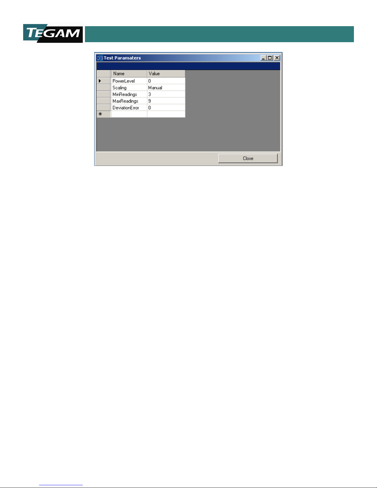
After all the Standards have been selected in PS-Cal, you are prompted to set the test parameters for the
test group. These parameters configure the specific options of the test methodology allowing you to fine
tune the specifics of each test methodology. For specifics on each option, see the supporting test
methodology documentation.
Note: Test parameters are editable after the template has been configured. Most test methodologies have
a PARAM button which loads the parameters window.
PS-Cal repeats this process of selecting the Measurement Methodology and Drivers until all Measurement
Methodologies and drivers have been configured.
Loading a Calibration Template
To load a calibration template in the PS-CAL menu, select Calibration Template -> Load and navigate
to the “C:\PS-Cal_V4\Calibration Templates\” directory. Select the calibration template of the power
sensor you are calibrating and then press Open.
Setting Additional Parameters in the Calibration Template
After creating a calibration template, there are some additional parameters and data that may need to be
updated. The parameters set variables defining how PS-Cal performs the calibratio n, and they vary with
each test methodology. Though these variables can be set a nd upda ted a t a ny time, for consistency, we
recommend that you update them when the template is first created, and if they are modified later, that
you save the updates back to the template file.
For each test in the power sensor template there is a parameters button on the screen. The parameters
window is opened by pressing the “Param.” button. Simply update the value in the value column and
press Close.
10 TEGAM WAY • GENEVA, OHIO 44041 440-466-6100 • FAX 440-466-6110 • www.tegam.com
Figure 4.4 Load a Calibration Template
4-3
Page 15
Section IV - Operatin g Inst ru ct ions
Figure 4.5 Configuring Parameters
In addition to the parameters data, the following values ma y need to be updated before the calibration
template is saved:
1) Uncertainties By default, PS-Cal calculates on the measurement uncertainties and updates the
column if the column contains “- -. “ If you would like PS-Cal to report uncertainties that are on
your scope, you can updat e this column and save the changes back to the template. This will force
PS-Cal to use your uncertainties on all reports.
2) OnLabel For many power sensors that have a calibration label, the calibration template can test
more frequencies than fit on the label. Under the C a l Factor test there is an OnLabel column.
This column controls what frequencies will be printed on the calibration label and the data can be
updated with Yes and No values. PS-Cal ignores this data for power sensors that do not require a
printed Cal Factor label.
Once all the data and parameters are set in the power sensor template, save the template to update it
with the changes. See “Saving a Calibration Template. “
10 TEGAM WAY • GENEVA, OHIO 44041 440-466-6100 • FAX 440-466-6110 • www.tegam.com
4-4
Page 16

Section IV - Operatin g Inst ru ct ions
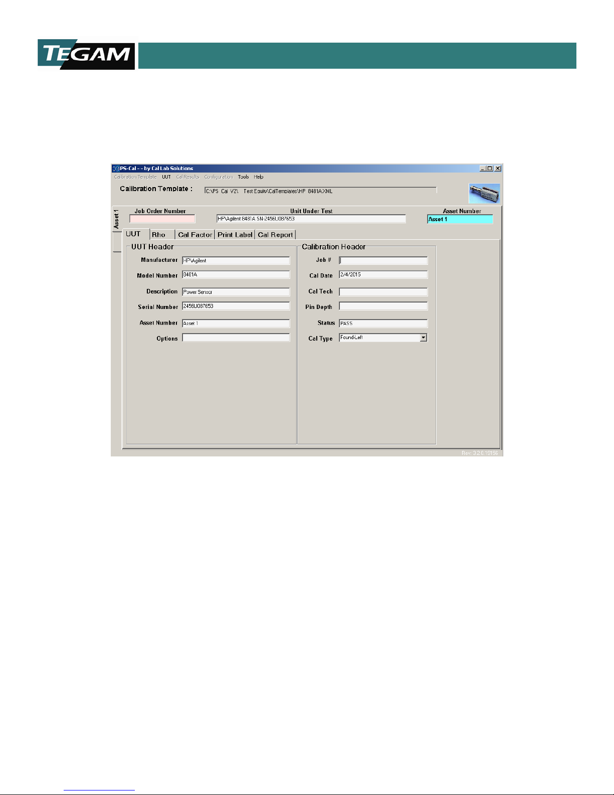
Running a Calibration
Once a power sensor template is loaded, PS-Cal displays one tab for each required test step. The exact
steps required for each power sensor and each measurement methodology vary. These tabs are loaded in
order of operation from left to right.
Figure 4.6 Running a Calibration
Two default tabs are loaded with every power sensor. The first is the UUT tab containing information
about the Unit Under Test (UUT, also known as Device Under Tes t, DUT) and the work order. Data such
as the UUT Serial number, Asset number, Job number, and the Calibration Technician (Cal Tech) w ho
performed the calibration must be updated on this tab.
The last tab is the Cal Report tab, which is used to print the report data for the calibration. Onc e all the
steps between the UUT tab and the Cal Report tab have been completed, the data is ready to print.
10 TEGAM WAY • GENEVA, OHIO 44041 440-466-6100 • FAX 440-466-6110 • www.tegam.com
Figure 4.7 Calibration Default Tabs
4-5
Page 17

Section IV - Operatin g Inst ru ct ions
Under each test procedure tab, there is a button bar w ith a button for each of the steps required to
complete that calibration step. Like the tabs, the buttons are organized in step order from left to right.
The exact buttons that appear on the form varies with each test methodology.
Figure 4.8 Calibration GUI
These buttons are enabled and disabled as required by the test procedure. A button remains disabled until
necessary prerequisite steps are performed. For example, the Cal button is turned off until the Configure
Station button has been pressed and the configure station operation has been completed. Then PS-Cal
turns on the Cal button and allows you to go to the next step in the calibration process.
Another button to make a special note of is the Halt button. This button is used to halt the application.
For example, if for some reason something was not hooked up correctly or you just need to stop the
program, simply press the Halt button and PS-Cal will stop executing the calibration steps and reset all
the standards to a safe state.
Saving Calibration Data
After you have completed a calibration (or at any point during the calibration), you can save the
calibration data to disk. We recommend you save your calibration data often, to prevent loss of data due
to a power outage or power failure.
To save your cal ibration data
1. Select UUT -> Save As and navigate to the “C:\PS-Cal_V4\CalResults\” directory.
2. Enter the file name of the calibration data you are saving (we recommend you use a standard
naming conventions of either <JobNumber>.xml or <AssetNumber><CalDate>.xml).
3. Press Save.
Uploading Calibration Data
If the sensor has an EEPROM (Electronic, Erasable Programmable Read Only memory), you can upload the
calibration data to the sensor.
To upload the calibration data:
1. Click the Upload Data tab.
2. Click the Download Data button. This brings up the data for viewing. You will also see the word
“Ready!” indicating that the data is now available for upload to the EEPROM on the sensor.
3. Click the Save/Backup Sensor Data to File button. This makes sure that the data is saved, in
case there is a malfunction with the sensor prior to uploading.
4. Select whether to upload the data for
a. Header
b. Cal Factors
c. Linearity
5. Click the Upload Cal Data button. A dialog box prompts you to cycle the power on the power sensor.
Note: to test that the data uploaded correctly, after cycling power on the sensor, with the sensor still
connected, click the Download Data button.
10 TEGAM WAY • GENEVA, OHIO 44041 440-466-6100 • FAX 440-466-6110 • www.tegam.com
4-6
Page 18

Section IV - Operatin g Inst ru ct ions
Printing a Calibration Label
If the sensor is a non-EEPROM based sensor (it does not have an Electronic, Erasable Programmable Read
Only memory), it may require a calibration label to be printed. In order to print the calibration label you
must have a compatible label printer. Once all the calibration steps have been completed the power
sensor calibration label is ready to be printed.
To print the calibration label:
6. Select the Print Label tab of the power sensor being calibrated. Under this is a report viewer tool
used to generate the label. PS-Cal supports several different label sizes.
7. Select the report size from the drop down.
8. Press the Run Report button. PS-Cal presents a print view of the report in the Report Viewer
window.
9. To print the report, press the Print button.
Note: If the report is generating a two page label, remove test points from the label by editing the
OnLabel under the Cal F ac t ors tab. Columns that contain “Yes” in the OnLabel field will be
printed on the label.
10 TEGAM WAY • GENEVA, OHIO 44041 440-466-6100 • FAX 440-466-6110 • www.tegam.com
4-7
Page 19

Section IV - Operatin g Inst ru ct ions
Printing the Calibration Report
Once all the steps of a calibration are completed, the results of the calibration are ready to be printed.
The last tab on the form is the Cal Report tab, which combines all the data from each tab into one single
report.
Figure 4.9 Print Calibration Report
To print the Calibration Report:
1. Select the Cal Report tab
2. Press the Run Report button. PS-Cal presents a print view of the report in the Report Viewer
window.
3. To print the report, press the Print button.
10 TEGAM WAY • GENEVA, OHIO 44041 440-466-6100 • FAX 440-466-6110 • www.tegam.com
Figure 4.10 Calibration Report Preview
4-8
Page 20
Section IV - Operatin g Inst ru ct ions
PS-CAL in Batch Mode
PS-Cal is able to calibrate power sensors in batch mode. Though PS-Cal can only calibrate a single sensor
at a time, Batch Mode allows the operator to configure that station to test one power sensor, and then use
that configuration to calibration the next sensor in the batch. This process saves time, because many
power sensor calibration configuration steps are time consuming.
Figure 4.11 Batch Mode
To use PS-Cal in Batch Mode:
1. Click on UUT in the menu bar
2. Select New.
This adds an Asset tab.
3. Label the tab by selecting it, and then selecting the UUT tab, and entering the asset number in the
Asset Number field.
4. The new asset tab is now labeled.
You can now select the newly added asset by clicking its tab along the left. Configuration information and
data collected on one power sensor is shared with all the power sensors that are open.
10 TEGAM WAY • GENEVA, OHIO 44041 440-466-6100 • FAX 440-466-6110 • www.tegam.com
4-9
 Loading...