

Page 1
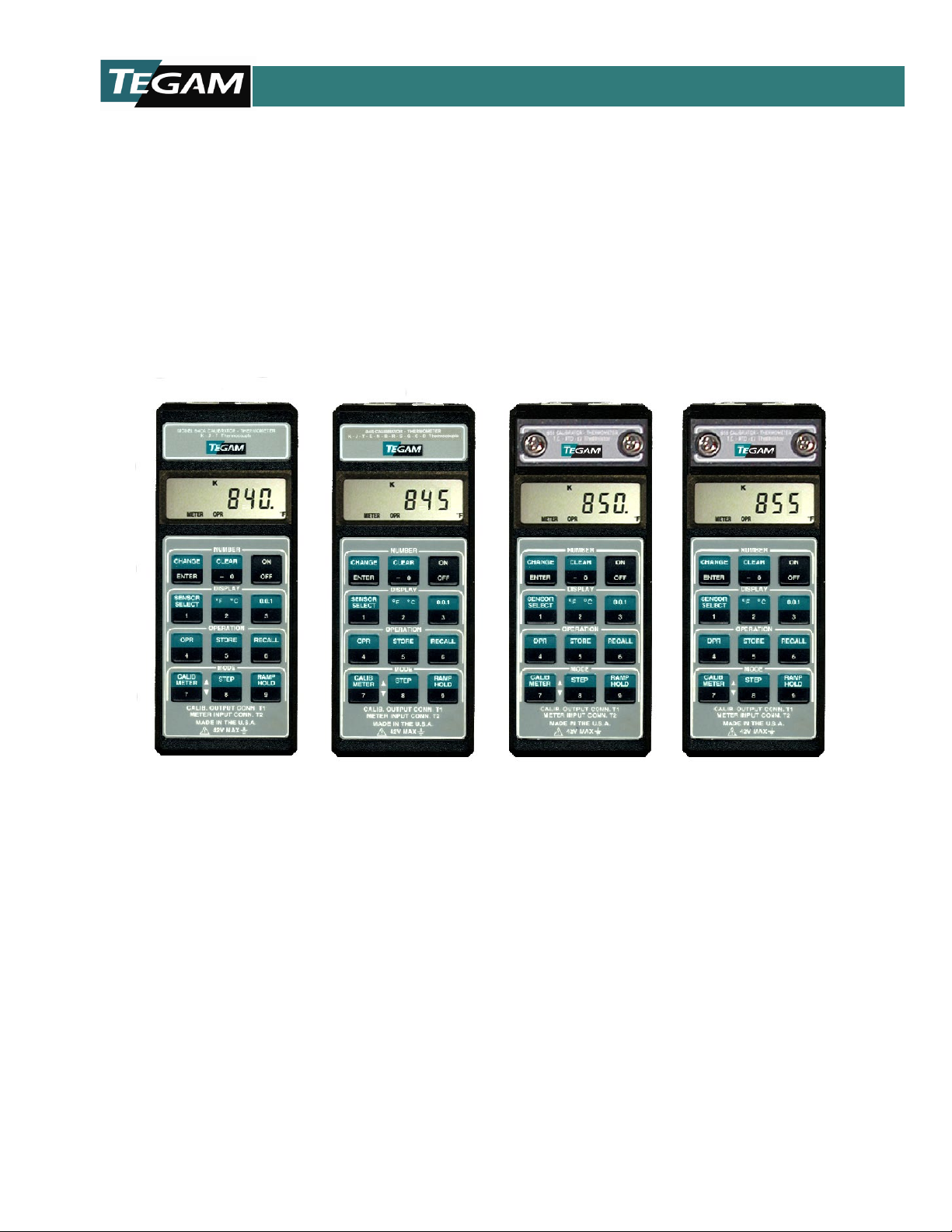
840A, 845, 850, 855
Digital Temperature Calibrator - Thermometer
MODEL 840A, 845, 850, 855
This owner’s manual was as current as possible when this product was manufactured. However,
products are constantly being updated and improved. Because of this, some differences may occur
between the description in this manual and the product you received.
Instruction Manual
PN# 840A-901-01CD
Publication Date: November 2019
REV. M
10 TEGAM WAY • GENEVA, OHIO 44041 • 440-466-6100 • FAX 440-466-6110 • sales@tegam.com
Page 2

TABLE OF CONTENT S
TABLE OF CONTENTS
General Information
Common Specifications ...................................................................... .................... 1
Unique Specifications .............................................................................................. 4
Features ............................................................................................................... 5
Manual Addenda .................................................................................................... 5
Unpacking and Inspection ....................................................................................... 6
Safety Information ................................................................................................. 6
Safety Precautions ................................................................................................. 6
Battery Installation/Replacement ..............................................................................8
Memory Backup .................................................................................................... 9
Operation with Rechargeable Battery ....................................................................... 9
Operating Instructions ............................................................................................ 9
1. Diagnostics and Error Messages .................................................................... 9
2. Initial Turn On .......................................................................................... 11
3. Meter Mode Operation (Thermocouple) ........................................................ 12
4. Meter Mode Operation (RTD, Thermistor, Ohms) ........................................... 12
5. Data Logging & Recall ............................................................................... 14
6. Calibrator Mode Operation (Thermocouples) ................................................. 16
7. Calibrator Mode Operation (RTD, Thermistor, Ohms) ...................................... 17
8. Storage and Recall of Calibrator Settings ..................................................... 19
9. Step Function ........................................................................................... 20
10. Ramp Function ........................................................................................ 20
Service Information
1. Calibration Procedures ............................................................................... 21
A. Thermocouple Calibration ...................................................................21
B. Resistance Calibration ........................................................................26
2. Calibration Verification ............................................................................... 30
3. Mechanical Parts Diagram .......................................................... ............. .. 36
Warranty ................................................................. .......................................... 37
Limitation of Warranty .......................................................................................... 37
Statement of Calibration .......................................................................... .............37
MAINTENANCE
DO NOT
10 TEGAM WAY • GENEVA, OHIO 44041 • 440-466-6100 • FAX 440-466-6110 • sales@tegam.com
INST
RUCT
IONS WITHIN THIS M
ATTE
MPT ANY SERVICING OTHER
INST
RUCTIONS UNLESS YOU ARE QUALIFIED TO DO SO.
ANUAL ARE FOR USE BY QUALIFIED SE
PERSONNEL ONLY.
THAN THAT CONTAINED IN THE OPERATION
RVICE
I
Page 3

GENERAL INFORMATION
GENERAL INFORMATION
This manual provides operating instructions and maintenance information for four temperature
instruments. These instruments are high performance calibrator-thermometers capable of
simulating and measuring a wide-variety of sensors. In addition, features such as data storage
and ramping further enhance their versatility.
It is recommended that you read this manual thoroughly, especially the sections on safety, prior
to operating these instruments.
COMMON SPECIFICATIONS
THERMOMETER INPUTS: THERMOCOUPLE; Miniature TC jack. RTD, OHMS, THERMISTOR; Tseries instrumentation connector.
CALIBRATOR OUTPUTS: THERMOCOUPLE; Miniature TC jack. RTD, OHMS, THERMISTOR; Tseries instrumentation connector.
THERMOCOUPLE TYPES: K, J, T, E, N, B, R, S, G, C, D.
RTD TYPES: 100Ω platinum (α = 0.00385)
1000Ω platinum (α= 0.00385)
THERMISTOR TYPE: 2252Ω (YSI Series 400).
RANGES: K; -200°C to 1372°C, -328°F to 2502°F
J; -210°C to 760°C, -346°F to 1400°F
T; -200°C to 400°C, -328°F to 752°F
E; -230°C to 1000°C, -382°F to 1832°F N; -200°C to 1300°C, -328°F to 2372°F
B; 500°C to 1820°C, 932°F to 3308°F R; 0°C to 1768°C, 32°F to 3214°F
S; 0°C to 1768°C, 32°F to 3214°F
G; 300°C to 2316°C, 572°F to 4201 °F C; 0°C to 2316°C, 32°F to 4201 °F
D; 0°C to 2316°C, 32°F to 4201 °F RTD; -200°C to 850°C, -328°F to 1562°F
THERMISTOR; -40°C to 150°C, -40°F to 302°F
OHMS; 0-999.99
0-9,999.9
0-99,999
ACCURACY: All stated accuracies are exclusive of sensor errors and lead resistance induced
errors. Refer to 'UNIQUE SPECIFICATIONS' for detail accuracy specs.
Ω
Ω
Ω
RESOLUTION: TEMPERATURE; 0.1 °/1° F/C
OHMS; 0.01Ω/0.1Ω/1Ω
10 TEGAM WAY • GENEVA, OHIO 44041 • 440-466-6100 • FAX 440-466-6110 • sales@tegam.com
1
Page 4

GENERAL INFORMATION
REPEATABILITY (1 week at constant ambient temperature):
K, J, T, E, N; ±0.2°F typ.
B, R, S, G, C, D; ±1.0°F typ.
RTD, THERMISTOR; ±0.1 °F typ.
OHMS; ±0.01 % rdg typ.
METER-MODE INPUT-CURRENT (THERMOCOUPLES): 50nA typ.
METER-MODE READING-RATE: 1 reading/second typ.
METER-MODE EXCITATION-CURRENTS:
100Ω RTD; <2mA
1000Ω RTD; <200
999.99Ω; <2mA
9999.9Ω; <200
99999Ω; <50
THERMISTOR; T ≤113°F <50
T> 113°F, <2mA
CALIBRATOR MODE OUTPUT LOAD (THERMOCOUPLES): 500Ω min.
CALIBRATOR-MODE EXCITATION-CURRENTS:
100Ω RTD; 0.5 - 1mA (0.1 - 2mA typ.)
1000Ω RTD; 50 - 100μA (10-200μA typ.)
999.99Ω; Same as 100Ω RTD
9999.9Ω; Same as 1000Ω RTD
99999Ω; 10 - 20μA (1 - 20μA typ.)
THERMISTOR; T ≤113°F, 10 - 20μA
MAXIMUM COMMON MODE VOLTAGE: 42V peak to earth.
KEYPAD: 12 momentary switches with tactile feedback select;
• On/Off
• Change/Enter
• Clear/-0
• Sensor Select/1
• °F/°C/2
• Resolution/3
• Operate/4
• Store/5
• Recall/6
• Calibrator/Meter/Up Ramp/7
• Calibrator Step/Down Ramp/8
• Calibrator Ramp/Meter Hold/9
T> 113°F, 0.5- 1mA
μ
A
μ
A
μ
A
μ
A
10 TEGAM WAY • GENEVA, OHIO 44041 • 440-466-6100 • FAX 440-466-6110 • sales@tegam.com
2
Page 5

GENERAL INFORMATION
DISPLAY: 5 digit LCD, 0.4" height, polarity indication and decimal point. Annunciators;
• Loaded Memory Locations (10 for data storage, 4 for ramp parameters)
• Low Battery (BAT)
• Number Change Mode (NUM)
• Calibrator Mode (CALIB)
• Meter Mode (METER)
• Operate Mode (OPR)
• Store Mode (STO)
• Recall Mode (RCL)
• Meter Hold (HOLD)
• Scale (°F/°C)
• Sensor Type
POWER OFF CONFIGURATION RETENTION: Instrument retains last selected;
• Sensor Type
• °F/°C Scale
• 0.1°/1° Resolution
• Calibrator/Meter Mode
• Memory Contents (data storage and ramp parameters).
DIAGNOSTICS: Display codes indicate following conditions;
• 'BAT': Low Battery
• 'OPEN': Open Input Thermocouple, RTD or Thermistor.
• 'E-1' (momentary): Invalid Keypad Entry
• 'E-2' (momentary): Ramp Function Not Installed
• 'HI': Temperature Reading or Keypad Entry Exceeds Rating
• 'LO': Temperature Reading or Keypad Entry Too Low For Accuracy
• LCD Test: During power-up, all segments and annunciators enabled momentarily
ENVIRONMENTAL LIMITS FOR OPERATING: 0°C to 50°C, less than 90% relative humidity
(R.H.) up to 35°C; reduce R.H. limit by 3%/°C from 35°C to 50°C.
ENVIRONMENTAL LIMITS FOR STORAGE: -35°C to 60°C, less than 95% relative humidity
(R.H.) up to 35°C; reduce R.H. limit by 3%/°C from 35°C to 60°C.
POWER: 9 volt alkaline battery (NEDA 1604A).
BATTERY LIFE, CONTINUOUS: 10 hrs. typical, alkaline; 3 hrs typical, Ni-Cd (rechargeable).
BATTERY INDICATOR: Display indicates BAT when less than 10% of life remains.
DIMENSIONS, WEIGHT: 7.0" x 2.9 x 1.1". Net weight 12 oz.
10 TEGAM WAY • GENEVA, OHIO 44041 • 440-466-6100 • FAX 440-466-6110 • sales@tegam.com
3
Page 6

GENERAL INFORMATION
UNIQUE SPECIFICATIONS
NOTE: The specifications below are specific to the model(s) as identified by
model number. The difference specifications are in addition to the
• MODEL 840A:
SENSOR SELECTION: K, J, T Thermocouples
ACCURACY: (18°C to 28°C ambient, 2 years):
K, J, T; ±0.5°F (rdg ≥ -50°F).
±0.04% rdg (rdg > 1250°F)
TEMPERATURE COEFFICIENT: From 0°C to 18°C, and 28°C to 50°C;
less than ±(0.006% rdg +0.03°C)/°C.
RAMP FUNCTION: Not Included.
BATTERY LIFE, CONTINUOUS: 16 hrs typical, alkaline; 4 hrs typical, Ni-Cd (rechargeable).
• MODEL 845:
SENSOR SELECTION: K, J, T, E, N, B, R, S, G, C, D Thermocouples
ACCURACY: (18°C to 28°C ambient, 2 years):
K, J, T, E, N; ±0.5°F (rdg ≥ -50°F)
B, R, S, G, C, D; ±1.7°F
TEMPERATURE COEFFICIENT: From 0°C to 18°C, and 28°C to 50°C;
K, J, T, E, N; ±(0.002% rdg + 0.03°C)/°C
B, R, S, G, C, D; ±(0.002% rdg + 0.1°C)/°C
RAMP FUNCTION: Included.
BATTERY LIFE, CONTINUOUS: 16 hrs typical, alkaline; 4 hrs typical, Ni-Cd (rechargeable).
• MODEL 850:
SENSOR SELECTION: K, J, T, E Thermocouples
100Ω Platinum RTD
2252Ω Thermistor
ACCURACY: (18°C to 28°C ambient, 2 years):
K, J, T, E; ±0.5 °F (rdg ≥ -50°F).
OHMS; ±0.04% range
RTD; ±0.2°F (rdg≥ - 50°F) (Calibrator mode)
Thermistor; ±0.5°F
TEMPERATURE COEFFICIENT: From 0°C to 18°C, and 28°C to 50°C;
K, J, T, E; ±(0.006% rdg + 0.03°C)/°C
RTD, THERMISTOR, OHMS; ±(0.006% rdg +0.012% rng)/°C
RAMP FUNCTION: Not Included.
10 TEGAM WAY • GENEVA, OHIO 44041 • 440-466-6100 • FAX 440-466-6110 • sales@tegam.com
'COMMON SPECIFICATIONS' found on pages 2-4.
±1.0°F (rdg < -50°F)
±1.0°F (rdg < -50°F)
1,000Ω/100,000Ω Resistance
±0.04% rdg (rdg > 1250°F)
±1.0°F (rdg <-50°F)
±0.5°F (rdg < - 50°F) (Calibrator mode)
±0.2°F ±0.04% rdg (rdg ≥ -50°F) (meter mode)
±0.5°F±0.04% rdg (rdg < -50°F) (meter mode)
4
Page 7

GENERAL INFORMATION
• MODEL 855:
SENSOR SELECTION: K, J, T, E, N, B, R, S, G, C, D Thermocouples
100Ω/1000Ω Platinum RTD
1,000Ω/10,000Ω Resistance
ACCURACY: (18°C to 28°C ambient, 2 years):
K, J, T, E, N; ± 0.5°F (rdg ≥ -50°F)
±1.0°F (rdg < -50°F)
B, R, S, G, C, D; ±1.7°F
RTD; ±0.2°F (rdg ≥ - 50°F) (Calibrator Mode)
±0.5°F (rdg < - 50°F) (Calibrator Mode)
±0.2°F ±0.04% rdg (rdg ≥ -50°F) (meter mode)
±0.5°F ±0.04% rdg (rdg < -50°F) (meter mode)
OHMS; ±0.02% range
TEMPERATURE COEFFICIENT: From 0°C to 18°C, and 28°C to 50°C;
K, J, T, E, N; ±(0.002% rdg + 0.03°C)/°C
B, R, S, G, C, D; ±(0.002% rdg + 0.1°C)/°C
RTD, OHMS; ±(0.002% rdg + 0.004% rng)/°C
RAMP FUNCTION: Included.
FEATURES
•Combination calibrator, thermometer and datalogger.
•Function selection and numeric data entered via 12 keyswitch color coded keypad.
•Keyswitches have tactile feedback.
•5 digit LCD includes annunciators for operating modes.
•Up to 11 thermocouple types, 2 RTD types, and thermistor.
•1° or 0.1° resolution over temperature range of each sensor.
•°F and °C scales.
•Reading hold mode.
•10 memory locations for saving meter readings and/or calibrator outputs.
•Step mode for quick sequential recall of calibrator outputs from memory.
•Manual/automatic ramping for testing controller setpoints.
•Conforms to ITS-90 thermocouple & RTD tables. Refer to 'Service Information' (page 23) for
more information.
•Dust proof, splash proof, drop proof construction.
•Built-in tilt stand/hanger for bench use or hands free field measurements.
•User friendly programming.
•Retains data and programming, even when turned off.
•Performs diagnostic tests and indicates fault conditions.
•Low battery and open sensor indications.
MANUAL ADDENDA
Improvements or changes to this manual will be explained on an addendum included with the
instrument. All change information should be incorporated immediately into the appropriate
places in the manual.
10 TEGAM WAY • GENEVA, OHIO 44041 • 440-466-6100 • FAX 440-466-6110 • sales@tegam.com
5
Page 8

GENERAL INFORMATION
UNPACKING AND INSPECTION
Each instrument is inspected both mechanically and electrically before shipment. Upon receiving
your instrument unpack all items from the shipping container and check for any obvious damage
that may have occurred during transit. Report any damage to the shipping agent. Retain and use
the original packing materials if reshipment is necessary.
SAFETY INFORMATION
SAFETY SYMBOLS AND TERMS
The symbol
The WARNING used in this manual explains dangers that could result in personal injury or
The CAUTION used in this manual explains hazards that could damage the instrument.
on the instrument denotes that the user should refer to the operating
instructions.
death.
SAFETY PRECAUTIONS
WARNING
These instruments are intended for use by qualified
personnel trained in the safe operation of electronic testing
equipment. Read the instruction manual thoroughly before
using, to become familiar with the instrument's operations
and capabilities.
Do not touch a temperature probe sheath when measuring
excessively high or low temperatures, or toxic substances.
Do not attempt to measure temperatures beyond the range
of the probe being used. Probe damage or personal injury
could result from exceeding a probe's maximum
Do not substitute a metal part for the nylon screw in the rear
case. Doing so will degrade electrical isolation of the case.
WARNING
WARNING
temperature rating.
WARNING
10 TEGAM WAY • GENEVA, OHIO 44041 • 440-466-6100 • FAX 440-466-6110 • sales@tegam.com
6
Page 9

GENERAL INFORMATION
WARNING
The American National Standards Institute (ANSI) states that
a shock hazard exists when probes or sensors are exposed
to voltage levels greater than 42VDC or 42V peak AC. Do
not use this instrument where voltages at the measurement
surface exceed these levels.
WARNING
The battery is accessible through a cover on the back of the
instrument. To avoid electrical shock hazard, disconnect all
temperature probes and sensors and turn the unit off before
removing the cover.
WARNING
Never use this instrument or any probe or sensor inside a
microwave oven.
CAUTION
Avoid making sharp bends in probe or sensor lead wires.
Bending lead wires at a sharp angle can damage the wire
causing probe failure.
CAUTION
Keep inputs electrically isolated from outputs. Do not
connect an external voltage source between the two
connectors, and avoid any external electrical pathways
between input and output (T2 & T1).
Failure to do so will disturb meter readings and calibrator
output levels. Damage to the instrument is also possible.
Where the meter and calibrator connectors are
simultaneously wired into a system lacking the above
isolation, it is necessary to use an "ungrounded" (i.e.
electrically isolated) probe at the thermometer input.
10 TEGAM WAY • GENEVA, OHIO 44041 • 440-466-6100 • FAX 440-466-6110 • sales@tegam.com
7
Page 10
GENERAL INFORMATION
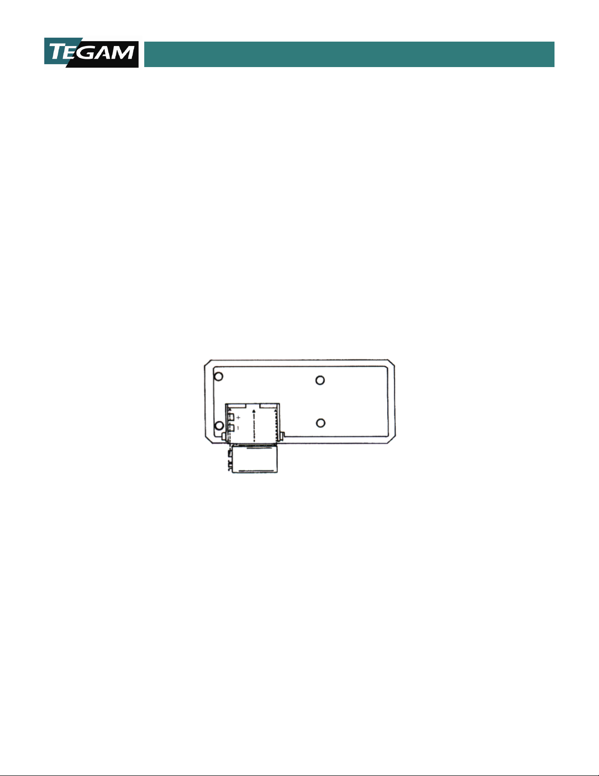
BATTERY INSTALLATION/REPLACEMENT
A 9V alkaline battery is supplied with the instrument but not installed. Read the following
installation instructions before attempting to install or remove the battery. Replacement batteries
should also be alkaline types.
WARNING
Turn the unit off and disconnect any input/output
connections before replacing the battery. Put the cover
back into place on the battery compartment before
resuming use of the instrument.
1. Remove the cover from the battery compartment by sliding it off in the direction of the
arrow located on the battery cover.
2. Remove the old battery.
3. Place the new battery in the battery compartment. Be sure to observe proper polarity.
4. Re-install the battery cover before resuming use of the instrument.
NOTES:
• Less than 10% of battery life remains when the BAT annunciator turns
on.
• When the battery is excessively discharged, the display is blanked.
• If the instrument is going to be stored for a long period of time or in a
high temperature environment, remove the battery to prevent leakage
damage.
• After a new battery is installed, allow approximately 5 seconds
for display turn-on the first time the unit is turned on. During
this period, microcomputer initialization is performed.
10 TEGAM WAY • GENEVA, OHIO 44041 • 440-466-6100 • FAX 440-466-6110 • sales@tegam.com
Figure 1. Battery Installation
8
Page 11

GENERAL INFORMATION
Vin:
90-110 VAC
108-132 VAC
198-242 VAC
50/60 Hz
50/60 Hz
50/60 Hz
MEMORY BACKUP
During battery replacement, the contents of user-programmed memory (data, operating modes,
etc.) can be saved. Prior to removing the old battery, turn off the instrument, and connect a
Model 80010 battery charger. Then exchange batteries, and disconnect the battery charger. Do
not leave the battery charger connected to instruments with non-rechargeable batteries.
OPERATION WITH RECHARGEABLE BATTERY
Model 80010 provides a 9-volt Ni-Cd battery and recharger suitable for use with the unit. This
battery provides 3-4 hours of continuous operation.
NOTE: Instrument accuracy is degraded while recharging the Ni-Cd battery, and
published specifications do not apply to measurements made during
recharging.
Turn off the instrument to recharge the battery. Allow 7 hours to recharge the battery fully. Then
unplug the recharger to avoid overcharging. Allow 20 minutes after charging before taking
measurements.
MODEL 80010 SPECIFICATIONS
Model
80010/100 80010 80010/220
Vout: 40 VDC @ 5mA 40 VDC @ 5mA 40 VDC @ 5mA
OPERATING INSTRUCTIONS
1. DIAGNOSTICS AND ERROR MESSAGES
Unit self-diagnostics provide fault condition readouts which are described below:
PROBLEM: LIKELY CAUSE:
Blank display, unit does not power-up. (1) Improper battery installation.
Check battery polarity.
BAT Annunciator. (1) Low battery voltage, install a new
Display reads OPEN. (1) No thermocouple, RTD or thermistor
10 TEGAM WAY • GENEVA, OHIO 44041 • 440-466-6100 • FAX 440-466-6110 • sales@tegam.com
(2) Dead battery.
battery. If problem persists, consult
factory.
is plugged into the meter input.
9
Page 12
GENERAL INFORMATION
Display reads E1 momentarily. (1) This indicates that an invalid keypad
entry has been made. Review keystroke
sequence, or consult manual for input
instructions.
Display reads E2 momentarily. (1) Attempt made to activate non-
installed ramp function.
NOTE: RAMP Function enabled on Models 845 and 855 only.
Display reads HI. (1) Meter-mode input-temperature
exceeds rating of selected sensor.
(2) Calibrator-mode keypad-entry
exceeds rating of sensor type.
Display reads LO. (1) Meter-mode input-temperature
too low for accurate measurement.
(2) Calibrator-mode keypad-entry too
low for accurate simulation.
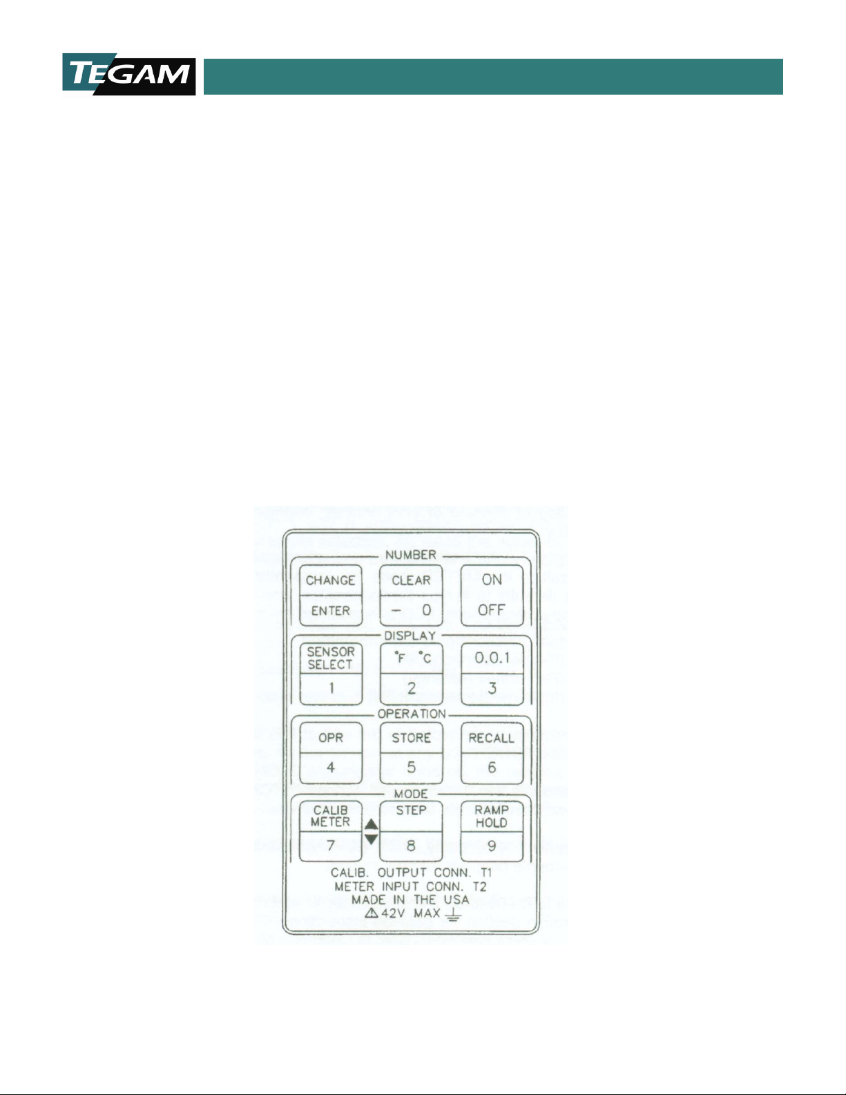
Figure 2. Keypad
10 TEGAM WAY • GENEVA, OHIO 44041 • 440-466-6100 • FAX 440-466-6110 • sales@tegam.com
10
Page 13

GENERAL INFORMATION
Figure 3. Display Test
2. INITIAL TURN ON
Turn on the instrument by depressing the ON-OFF keyswitch once (Figure 2). At power-up, the
unit first performs a display test. All segments and annunciators of the liquid crystal (LCD) are
momentarily turned on for visual confirmation by the user (Figure 3).
NOTE: In case of missing or poor-contrast segments, contact factory.
If the unit is turning on for the first time after a new battery is installed, it will
default to the METER mode (ie. temperature measurement
thermocouples, and °F readings with 0.1° resolution. The corresponding LCD annunciators are
enabled:
METER : (Unit functioning as a thermometer)
K : (K-type thermocouple)
°F : (Fahrenheit readings)
OPR : (Instrument is operational)
If no input thermocouple is connected to the unit at this time, the numeric segments will indicate
"OPEN".
Plugging a thermocouple into the meter jack (connector T2, on the top right side) will give actual
thermocouple temperature readings.
NOTE: To obtain full accuracy, allow 1-2 minutes after connecting a
thermocouple plug, for thermal setting.
If the instrument is to be used as a thermometer or ohmmeter, refer to the Meter Mode Operation
section for detailed instructions. For use as a temperature-calibrator or ohms simulator, refer to
Calibrator Mode Operation.
10 TEGAM WAY • GENEVA, OHIO 44041 • 440-466-6100 • FAX 440-466-6110 • sales@tegam.com
11
operation). It also defaults to K-type
automatically
Page 14

GENERAL INFORMATION
3. METER MODE OPERATION (Thermocouples) Set-Up:
1. Turn on instrument by depressing the ON/OFF key.
2. Check that the BAT annunciator turns off following the power-up LCD test.
If it does not turn off, less than 10% of battery remains. Refer to Battery Installation/Replacement
instructions.
3. If the meter is already in the METER mode, the METER annunciator will
be on. Otherwise the calibrator mode is enabled and the CALIB annunciator is on. Depress the
METER key to return to meter mode.
4. Connect an input thermocouple (TC) to connector T2. Select the appropriate TC Type with the
select-key. A display annunciator will indicate the selected TC-type.
NOTE: Space and legibility constraints on the display preclude the use of
dedicated annunciators for the less common tungsten- rhenium
thermocouple types (G, C & D). Instead, these types are annunciated
momentarily on the alpha-numeric display when first selected. Both T
and R annunciators remain on to indicate a Tungsten-Rhenium
selection. To recall the actual G, C, D selection, turn the unit off, then
on again for another momentary readout.
5. Select temperature scale with °F/°C key. The corresponding annunciator is enabled.
6. Select display resolution with 0.0.1 key.
Hold:
Meter readings can be put on hold at any time by depressing the HOLD key. At this time,
the HOLD annunciator turns on, the reading is frozen, and all keys (except ON/OFF and
HOLD) are locked out. Depress the HOLD key again to return to real-time readings, and
re-enable the keypad.
4. METER MODE OPERATION (RTD, Thermistor & Ohms) Set-Up:
NOTE: Set-up is retained during power-off.
1. Connect a sensor or unknown resistance to the instrument as shown in Figures 4, 5, or 6.
The 2-wire configuration is simplest, but includes lead-wire resistance in the measurement. 2-wire
measurements are generally limited to high resistance sensors (e.g. 1000-ohm RTDs, 2252-ohm
thermistors).
Lead resistance errors are compensated for in 3-wire configurations. However, full
compensation requires equal resistance in each lead. This configuration is common with 100ohm RTDs.
10 TEGAM WAY • GENEVA, OHIO 44041 • 440-466-6100 • FAX 440-466-6110 • sales@tegam.com
12
Page 15

GENERAL INFORMATION
In 4-wire configurations, accuracy is unaffected by lead resistance and resistance differences
between leads.
NOTE: These instruments measure input voltages on all 4 terminals, and are able
to distinguish between 2-4 and 3-wire hookups. Switching between these
measurement modes is automatic.
2. Set instrument to METER mode.
3. Use the Sensor-Select key to set the instrument to the appropriate function and range.
NOTE: Due to limited display area, 100Ω and 1000Ω RTD's are indicated on
the display by a momentary readout of "RTD-100" (or "RTD-1000")
when first selected.
Thermistors are identified by a momentary alpha-numeric readout of "Y-
400" (signifying YSI Series-400 type thermistor).
Any of these readouts can be recalled by turning the unit off and back
on
.
(RTD, Thermistor, etc.)
Figure 4. 2-Wire Resistance Measurement
Figure 5. 3-Wire Resistance Measurement
10 TEGAM WAY • GENEVA, OHIO 44041 • 440-466-6100 • FAX 440-466-6110 • sales@tegam.com
13
Page 16

GENERAL INFORMATION
Figure 6. 4-Wire Resistance Measurement
5. DATA LOGGING AND RECALL
Operating as a meter, the unit can save and recall up to 10 readings (each with independent
parameters: eg. °F/°C, TC-type and resolution) in random access memory.
To Save Readings:
1. While in the METER OPR mode, depress the STORE key. Note that the OPR annunciator is replaced
by STO.
2. Next depress one of the memory location numbers (keys 0, 1, ..., 9). The corresponding
memory annunciator turns on and the meter returns momentarily to the OPR mode, displaying
thermocouple temperature.
eg. STORE 7
NOTES:
• The enabled location annunciator indicates that the meter reading
at the instant that the location number key was pressed, was stored in
memory.
• When data is stored in a location already filed with data, the new data
replaces the old.
• Stored readings are retained during power-off.
To Recall Readings:
1. While in the METER OPR mode, readings stored earlier can be displayed by first depressing the
RECALL key. Note that the OPR annunciator is replaced by RCL, and all memory location
10 TEGAM WAY • GENEVA, OHIO 44041 • 440-466-6100 • FAX 440-466-6110 • sales@tegam.com
14
Page 17

GENERAL INFORMATION
annunciators are blanked.
2. Next depress the keypad number corresponding to the desired location.
Note that the annunciator for this location turns on and the memory contents are displayed.
3. Several stored readings can be randomly recalled by a key sequence such as:
4. To return the meter to the operate mode, depress OPR after recalling the last reading. All
active location annunciators will turn on again, together with the OPR annunciator.
NOTE: Recalling data from unused (i.e. empty) locations will give a zero
To Erase Data Locations (Meter Mode):
1. Individual data locations can be erased by recalling the location to be cleared, followed by a
CLEAR key input. Note that the annunciator for the cleared location is turned off,and the meter
returns to OPR.
NOTE: There is no need to clear a location if new data is ready for saving in this
eg. RECALL 3
RECALL 5
RECALL 2 etc.
reading.
eg. RECALL 3
CLEAR
location. Just STORE the new data. It will write over and delete the old.
Figure 7.
10 TEGAM WAY • GENEVA, OHIO 44041 • 440-466-6100 • FAX 440-466-6110 • sales@tegam.com
15
Page 18

GENERAL INFORMATION
6. CALIBRATOR MODE OPERATION (Thermocouples) Set-Up:
1. Turn on the instrument by depressing the ON/OFF key.
2. Check that the BAT annunciator turns off after display check. If not, refer to Battery
Installation/Replacement instructions.
3. When operating as a calibrator, the display indicates CALIB. Should the instrument be
in the METER mode, press the CALIB key to change to the calibrator function.
4. Select the thermocouple type that will be used.
NOTE: Space and legibility constraints on the display preclude the use of
dedicated annunciators for the less common tungsten-rhenium
thermocouple types (G, C, & D). Instead, these types are
annunciated momentarily on the alpha-numeric display when first
selected. Both T and R annunciators remain on to indicate a
Tungsten-Rhenium selection. To recall the actual G, C, D selection,
turn the unit off, then on again for another momentary readout.
5. Select the desired temperature scale (°F/°C key).
6. Select the resolution desired (0.0.1 key).
NOTE: With 1° resolution, one less key stroke will be required to enter
calibrator output temperatures via the keypad.
7. The unit accepts numeric inputs by first changing the keypad to its number-entry mode (NUM)
by depressing the CHANGE/ENTER key once.
The numeric display will flash, the OPR annunciator will turn off, and the NUM annunciator will
turn on. Key in desired temperature value, most significant digit first. After the desired
temperature value is keyed in, press CHANGE/ENTER to return to OPR mode.
To enter a value of 212° with 0.1° resolution, the following keystrokes are used:
NOTES:
CHANGE/ENTER, 2, 1, 2, 0, CHANGE/ENTER
• Invalid numeric entries (eg. a temperature beyond the span of
selected TC type) will cause a corresponding error code to be
displayed.
• To enter negative (ie. minus) temperatures, press the -0 key first
when in the NUM mode. The first press on this key enters the negative
sign. Subsequent presses enter zeros.
the
• To correct a numeric entry while in the NUM mode, press the
CHANGE/ENTER key twice. This will return number entry to the
beginning of a new number.
10 TEGAM WAY • GENEVA, OHIO 44041 • 440-466-6100 • FAX 440-466-6110 • sales@tegam.com
16
Page 19

GENERAL INFORMATION
• To return the calibrator output to 0° while in the OPR mode, press
the CLEAR key.
• The unit can be used as a convenient °F to °C or °C to °F calculator.
For example, to convert 77°F to a Celsius reading, go to the CALIB OPR mode, enter the reading
to be converted, and change scale.
eg.°F
CHANGE/ENTER
77
CHANGE/ENTER
°C (Display reads 25°C)
7. CALIBRATOR MODE OPERATION (RTD, Thermistor & Ohms)
NOTE: The 850/855 requires a steady current to function properly in the
calibration mode. Some transmitters operate with a pulsating current
which won't work with the 850/855. These devices are normally provided
with a calibration mode which when enabled stops sending pulsating
current and supplies a steady current. Disabling the mode returns the
transmitter to its normal operating state.
Set-Up:
1. Connect measurement equipment under test (eg. RTD thermometer, ohmmeter etc.) to the
instrument as shown in Figures 8, 9, or 10.
The same performance tradeoffs apply to 2, 3 and 4-wire simulations as to 2, 3, and 4-wire
measurements. Refer to RTD, Thermistor and Ohms Meter-Mode section above for wiring
guidelines.
2. Set instrument to CALIBRATOR mode.
3. Use the sensor-select key to set the instrument to the appropriate function and range.
Figure 8. 2-Wire Resistance Simulation
10 TEGAM WAY • GENEVA, OHIO 44041 • 440-466-6100 • FAX 440-466-6110 • sales@tegam.com
17
Page 20

GENERAL INFORMATION
Figure 9. 3-Wire Resistance Simulation
NOTE: To ensure accurate calibrator outputs, observe specified limits to
excitation currents. If in doubt, check current levels with a DMM in
series with either source lead (1 or 3).
NOTE: Due to limited display area, 100Ω and 1000Ω RTD's are indicated on
the display by a momentary readout of "RTD-100" (or "RTD-1000")
when first selected.
Thermistors are identified by a momentary alpha-numeric readout of
"Y-400" (signifying YSI Series-400 type thermistor).
10 TEGAM WAY • GENEVA, OHIO 44041 • 440-466-6100 • FAX 440-466-6110 • sales@tegam.com
Figure 10. 4-Wire Resistance Simulation
18
Page 21

GENERAL INFORMATION
Any of these readouts can be recalled by turning the unit off and back
on.
8. STORAGE AND RECALL OF CALIBRATOR SETTINGS
While operating as a calibrator, the unit can store and recall up to 10 output settings (each with
independent parameters, eg. °F/°C, sensor type, and resolution) in random access memory.
To Store Outputs:
1. While in the CALIB OPR mode, depress the STORE key. Note that the OPR annunciator is
replaced by STO.
2. Next depress one of the memory location numbers (keys 0, 1, 2, .... 9).
The corresponding memory annunciator turns on, and the calibrator returns to the OPR mode.
To Recall Outputs:
1. While in the CALIB OPR mode, set-ups saved earlier in memory can be recalled to program the
calibrator output. First depress the RECALL key to recall a set-up.
Note that the RCL annunciator turns on, OPR turns off, and all memory locations annunciators
are blanked.
2. Next press the key with the number corresponding to the desired memory location. The
corresponding annunciator turns on, and the LCD updates to show the new calibrator setting.
3. Several stored set-ups can be randomly recalled by a key sequence such as:
4. To return the unit to the CALIB OPR mode after recalling the last set-up, press the OPR key.
10 TEGAM WAY • GENEVA, OHIO 44041 • 440-466-6100 • FAX 440-466-6110 • sales@tegam.com
eg. STORE 2
NOTES:
• The enabled memory annunciator shows that the output set-up has
been saved.
• When a set up is stored in a location already in use, the new set-up
replaces the old.
• Saved set-ups are retained during power-off.
• To store a reading of 0° just press the CLEAR while in the CALIB OPR
mode. Then depress STORE and a location number.
eg. RECALL 8
eg. RECALL 6
RECALL 3
RECALL 9 etc.
NOTES:
• Any other key except ON/OFF and CLEAR will also return the OPR
19
Page 22

GENERAL INFORMATION
mode.
• Set-ups recalled from unused locations will display and output 0°.
• Calibrator set-ups can be recalled even when the unit is func- tioning
in the meter mode. The same 10 storage locations are shared in both
meter and calibrator modes.
• Readings stored in memory while operating as a METER, can be
recalled in the CALIB mode. In this unusual application, the unit
generates calibrator outputs that simulate earlier stored meter inputs.
To Erase Set-Up Locations (Calibrator Mode):
1. Individual set-up locations can be erased by recalling the location followed by a press to the
CLEAR key.
eg. RECALL 5
CLEAR
9. STEP FUNCTION
When operating in the CALIBRATOR mode, the STEP key will sequentially recall data stored in
memory (up to 10 steps). At each step, the calibrator will display and output these parameters.
The STEP function is non-functional in METER mode.
10. RAMP FUNCTION: Models 845 and 855 only
This feature allows the calibrator to automatically ramp up and down a user- defined staircase.
Up and down keys allow for manual ramping by the user.
To activate the RAMP function, the instrument must first be in the CALIBRATE mode. Depress the
RAMP key once to enter the ramp programming mode. The display reads "prog", with memory
annunciators 1-4 flashing. A second press to the RAMP key starts automatic ramping. A third
press turns off the RAMP function.
User definable RAMP memory locations 1, 2, 3, & 4 are dedicated to storage of RAMP
parameters; step size, staircase starting point, upper limit, and lower limit respectively. These
memory locations are accessible only when in RAMP “prog” mode, and are independent of the
other 10 memory locations. Numeric values for RAMP parameters can be set, stored, recalled and
cleared like other calibrator settings. (Refer page 16, CALIBRATOR MODE OPERATION).
When automatic ramping is in progress, a press to either the 7 or 8 key activates manual upramping or down-ramping respectively. Whenever the battery is replaced (and memory backup is
not performed), the ramp parameters default to factory-set values:
LOC 1 Step Size =10°F (K TC)
2 Start Point = 500°F
3 High Limit = 550°F
10 TEGAM WAY • GENEVA, OHIO 44041 • 440-466-6100 • FAX 440-466-6110 • sales@tegam.com
20
Page 23

SERVICE INFORMATION
SERVICE INFORMATION
WARNING
All service information is intended for qualified
electronic maintenance personnel only.
NOTE: Instruments with the rev. number mentioned below or greater
conforms to ITS-90 thermocouple and RTD tables.
Model Software Rev. Software Rev.
(Thermocouple) (RTD)
840A 6.10 NA
845 3.10 NA
850 5.10 5.11
855 4.20 4.22
(Software revision is marked on a label attached to integrated-circuit U1 on the mother-board.)
1. CALIBRATION PROCEDURES
This is a two-part procedure. Products with thermocouple functions only, follow the
Thermocouple Calibration procedure below. Products with resist an ce fu nct ions (RTD, thermistor,
ohms) follow first the Thermocouple Calibration procedure, then the Resistance Calibration
procedure.
A. THERMOCOUPLE CALIBRATION Test
Equipment Required:
1. Thermocouple simulator (Ectron 1120, or equivalent) calibrated to ITS-90.
2. Microvolt DMM (Fluke 8840A, or equivalent)
3. Calibration cables, per Figures 11, 12, 13.
NOTE: The copper constantan cables used in Figures 12 and 13 need to be
calibrated. Voltage errors in these cables should be compensated at the
simulator.
4. Calibration cover (820-307-4).
Ambient Conditions:
Units should be calibrated at an ambient temperature of 23°C ±1°C, with relative humidity less
than 80%.
10 TEGAM WAY • GENEVA, OHIO 44041 • 440-466-6100 • FAX 440-466-6110 • sales@tegam.com
21
Page 24

SERVICE INFORMATION
Preparation for Calibration:
1. Remove battery from unit under test (U.U.T.). Refer to Battery Installation/Replacement
section in the manual.
2. Remove bottom-cover from U.U.T. Refer to Disassembly Instructions.
3. Remove calibration-jumpers J1 and J2 from printed-circuit board.
NOTE: Removal of J1, J2 causes partial loss of previously stored
calibration data. Do not remove these jumpers unless recalibration
is intended.
4. Install calibration cover in place of bottom-cover.
5. Re-install battery.
6. Hook up test-equipment, calibration cables, and U.U.T. per Figure 11.
7. Turn on DMM and TC simulator for warmup. Allow at least 30 minutes.
8. Set the DMM to 200mV DC range.
9. Set the TC simulator to its COPPER output mode, with a reference temperature of 32.0°F.
10. Turn on U.U.T. and verify that "RTD" and "Ω," annunciators are flashing on the display. This
verifies removal of J1 and J2 respectively.
NOTE: Flashing "RTD" indicates that zero-offset corrections can be stored in
EEPROM. It also indicates that cold-junction compensation is disabled.
Flashing 'Ω’ indicates that error corrections for the cold-junction sensors
can be stored or recalled from EEPROM.
11. Clear the EEPROM locations used to store E1 (meter cold-junction sen so r er ror) and E2
(calibrator cold-junction sensor error) as follows:
a. Set U.U.T to CALIB, OPR, K, °F mode.
b. Key in: CHANGE/0.0/ENTER/STO/1/OPR (E1 is set to 0.0°F)
c. Key in: CHANGE/0.0/ENTER/STO/2/OPR (E2 is set to 0.0°F)
NOTE: Both 1 & 2 memory annunciators should be turned on, but the "RTD"
annunciator will have turned off.
d. Perform RECALL 1 and RECALL 2 to verify storage of 0.0°F in both locations.
NOTE: At the completion of calibration, E1 and E2 will be saved in EEPROM.
Memory locations 1 and 2 will be free for normal use.
e. Set U.U.T. to METER, OPR, K, °F.
f. Turn U.U.T. OFF, then ON to re-enable 'RTD' and 'Ω,' annunciators.
10 TEGAM WAY • GENEVA, OHIO 44041 • 440-466-6100 • FAX 440-466-6110 • sales@tegam.com
22
Page 25

SERVICE INFORMATION
Calibration Adjustments:
NOTE: Do not deviate from the calibration adjustment sequence that follows.
This will ensure that adjustments to be stored in EEPROM go to the
1. Set meter-mode zero and gain adjustments per Table 1.
2. Press OPR key (RTD annunciator turns off).
3. Set U.U.T. to CALIB, OPR, K, °F.
4. Turn U.U.T. OFF, then ON, to re-enable RTD & Ω, annunciators.
5. Set calibrator-mode zero and gain adjustments per Table 2. Press CHANGE and ENTER at the
completion of each step in Table 2.
6. Press OPR key (RTD annunciator turns off).
7. Install J1 jumper.
8. Set U.U.T. to METER, OPR, T, °F
9. Change TC simulator output to Type T, 32°F, ALLOY mode.
10. Reconfigure calibration set-up per Figure 12. Allow 2-3 minutes for thermal stabilization.
11. Calculate E1 as follows: E1 = U.U.T. Reading — 32.0.
12. Set U.U.T. to CALIB, OPR, T, °F mode.
13. Store E1; CHANGE/(E1 value)/ENTER/STO/1/OPR.
14. Go to METER mode, and verify U.U.T. reading of 32.0 ±0.1°F.
15. Reconfigure calibration setup per Figure 13. Leave simulator output at 32°F, Type T, ALLOY
mode. Allow 2-3 minutes for thermal stabilization.
16. Set U.U.T. to CALIB mode, 32°F, Type T.
17. Calculate E2 as follows:
E2 = DMM Reading (in μV)
(For example with DMM reading of +11μV, E2 = -0.5°F)
18. Store E2; CHANGE/(E2 value)/ENTER/STO/2/OPR.
19. Install J2 jumper.
20. Re-set U.U.T. output to 32°F, DMM reading should be 0±2
21. Turn OFF U.U.T.
22. Thermocouple calibration is complete. Remove calibration cover. Reinsta ll original back-cover,
unless going on to Part B (Resistance Calibration).
correct locations.
-22
μ
V.
10 TEGAM WAY • GENEVA, OHIO 44041 • 440-466-6100 • FAX 440-466-6110 • sales@tegam.com
23
Page 26

SERVICE INFORMATION
STEP
SENSOR SELECT
U.U.T. INPUT
ADJUST
U.U.T. READING*
1
K
0.000mV
P1
2
K
54.856mV
P11
3
Repeat steps 1 & 2 as required
4
J
0.000mV
P1
5
T
0.000mV
P1
6
E
0.000mV
P1
7
N
0.000mV
P1
8
B
1.439mV
P1
9
R
0.000mV
P1
10
S
0.000mV
P1
11
G
2.238mV
P1
12
C
0.000mV
P1
13
D
0.000mV
P1
STEP
SENSOR SELECT
U.U.T. INPUT
ADJUST
DMM READING*
1
K
P1
0.000mV±1µV
2
K
P41
54.856mV±1µV
3
Repeat steps 1 & 2 as required
4
J
P1
0.000mV±1µV
5
T
P1
0.000mV±1µV
6
E
P1
0.000mV±1µV
7
N
P1
0.000mV±1µV
8
B
P1
1.439mV±1µV
9
R
P1
0.000mV±1µV
10
S
P1
0.000mV±1µV
11
G
P1
2.238mV±1µV
12
C
P1
0.000mV±1µV
13
D
P1
0.000mV±1µV
Table 1: Meter-Mode Zero & Gain Adjustments
*exclusive of noise
Table 2: Calibrator-Mode Zero & Gain Adjustments
32.0±0.1°F
2500.0±0.1°F
32.0±0.1°F
32.0±0.1°F
32.0±0.1°F
32.0±0.1°F
1000.0±0.5°F
32.0±0.5°F
32.0±0.5°F
600.0±0.2°F
32.0±0.2°F
32.0±0.2°F
*exclusive of noise
10 TEGAM WAY • GENEVA, OHIO 44041 • 440-466-6100 • FAX 440-466-6110 • sales@tegam.com
32.0°F
2500.0°F
32.0°F
32.0°F
32.0°F
32.0°F
1000.0°F
32.0°F
32.0°F
600.0°F
32.0°F
32.0°F
24
Page 27

SERVICE INFORMATION
Figure 11. Calibration Setup, Copper Mode.
Figure 12. Calibration Setup, Meter Mode.
Figure 13. Calibration Setup, Calibrator Mode.
10 TEGAM WAY • GENEVA, OHIO 44041 • 440-466-6100 • FAX 440-466-6110 • sales@tegam.com
25
Page 28

SERVICE INFORMATION
B. RESISTANCE CALIBRATION
NOTE: Thermocouple and resistance calibrations are independent. However,
potentiometer P1 is used in both thermocouple and resistance
calibrations to set EEPROM constants. Follow calibration procedures
carefully to ensure that thermocouple and resistance calibrations do not
disturb one another.
Test Equipment Required:
1. Resistance Decades (General Resistance RTD-100, RTD-500/1000, and RDS-54, or equivalent).
2. Current Source (Fluke 5101B, or equivalent).
3. Digital Multimeter (Fluke 8840A, or equivalent).
4. Calibration cables per Figure 14.
Ambient Conditions:
Unit should be calibrated at an ambient temperature of 23°C±1°C, with relative humidity less
than 80%.
Preparation for Calibration:
1. Turn off unit, and remove bottom-cover. Refer to Disassembly Instructions.
2. Secure battery with a piece of adhesive tape.
NOTE: Momentary loss of battery power during the following calibration will
invalidate previous adjustments, both resistance and thermocouple.
3. Hook up test-equipment and unit per Figure 14.
4. Set current-source to 1mA, STANDBY mode.
5. Set DMM to 2V DC range.
6. Turn on unit.
7. Set unit to METER mode, RTD-100, °F.
8. Turn off unit. Remove jumper J1. Turn on unit. 'RTD' annunciator should be flashing.
NOTES: Flashing 'RTD' indicates that calibration adjustments will be written to
memory. Avoid selecting thermocouple functions while in this mode.
Should it be necessary to scroll through thermocouple functions, first
press the OPR key (disables flashing 'RTD'), and start again at Step 7
above.
10 TEGAM WAY • GENEVA, OHIO 44041 • 440-466-6100 • FAX 440-466-6110 • sales@tegam.com
26
Page 29

SERVICE INFORMATION
Figure 14. Resistance Calibration Setup
10 TEGAM WAY • GENEVA, OHIO 44041 • 440-466-6100 • FAX 440-466-6110 • sales@tegam.com
27
Page 30

SERVICE INFORMATION
STEP
SENSOR
SELECT
UNIT
OUTPUT
ADJUST
VERIFY
DMM
READING*
1
RTD-100
390.48Ω
P1**
2
RTD-100
100.00Ω
√
3
RTD-100
18.52Ω
√
4
RTD-1000
3904.8Ω
P1**
5
RTD-1000
1000.0Ω
√
6
1,000Ω
900.0Ω
P1
900.00Ω
7
1,000Ω
1.00Ω
√
1.00±0.10Ω
8
10,000Ω
9000.0Ω
P1
9000.0Ω
9
10,000Ω
10.0Ω
√
10.0±1.0Ω
Calibration Adjustments:
NOTE: Do not deviate from the calibration adjustment sequence that follows.
This will ensure that adjustments to be stored in EEPROM go to the
1. Perform meter-mode adjustments and verifications per Table 3 (use Table 5 for RTD-Thermistor
models).
2. Press OPR key (Flashing 'RTD' annunciator turns off).
3. Install J1 jumper.
4. Set unit to CALIB mode, RTD-100, °F.
5. Switch current source to OPERATE mode.
6. Perform calibrator-mode adjustments and verifications per Table 4 (use Table 6 for RTDThermistor models).
7. Turn off unit. Remove tape holding battery.
8. Re-install back cover. Resistance-function calibration is complete.
Table 3: Calibration of Meter-Mode Resistance Functions (RTD-100/1000)
correct locations.
*exclusive of noise
** adjust as necessary to obtain steps 2,5.
1562.0±0.5°F
32.0±0.1°F
-328.0±0.2°F
1562.0±0.5°F
32.0±0.1°F
10 TEGAM WAY • GENEVA, OHIO 44041 • 440-466-6100 • FAX 440-466-6110 • sales@tegam.com
28
Page 31

SERVICE INFORMATION
STEP
SENSOR
SELECT
UNIT
OUTPUT
CURRENT
SOURCE INPUT
ADJUST
VERIFY
DMM READING*
1
RTD-100
1mA
P38 0.39048V
2
RTD-100
1mA
√
0.10000±0.00003V
3
RTD-100
1mA
√
0.01852±0.00006V
4
RTD-1000
100µA
P51 0.39048V
5
RTD-1000
100µA
√
0.10000±0.00003V
6
1,000Ω
900.00Ω
1mA
√
0.90000±0.00010V
7
1,000Ω
1.00Ω
1mA
√
0.00100±0.00010V
8
10,000Ω
9000.0Ω
100µA
√
0.900000±0.00010V
9
10,000Ω
10.0Ω
100µA
√
0.000100±0.00010V
STEP
SENSOR
SELECT
UNIT
OUTPUT
ADJUST
VERIFY
DMM READING*
1
RTD-100
390.48Ω
P1
2
RTD-100
100.00Ω
√
3
RTD-100
18.52Ω
√
4
1,000Ω
900.0Ω
P1 900.00Ω
5
1,000Ω
1.00Ω
√
1.00±0.20Ω
6
100,000Ω
90,000Ω
P1 90,000Ω
7
100,000Ω
100Ω
√ 100±20Ω
8
Thermistor
47.0Ω
P1
9
Thermistor
2252Ω
√
10
Thermistor
75,790Ω
√
Table 4: Calibration of Calibrator-Mode Resistance Functions (RTD-100/1000)
1562.0°F
32.0°F
-328.0°F
1562.0°F
32.0°F
* exclusive of noise.
Table 5: Calibration of Meter-Mode Resistance Functions (RTD-Thermistor)
1562.0°F ±0.6
* exclusive of noise.
32.0±0.2°F
-328.0±0.5°F
293.0°F
77.0±0.2°F
-40.0±0.2°F
10 TEGAM WAY • GENEVA, OHIO 44041 • 440-466-6100 • FAX 440-466-6110 • sales@tegam.com
29
Page 32

SERVICE INFORMATION
STEP
SENSOR
SELECT
UNIT
OUTPUT
CURRENT
SOURCE INPUT
ADJUST
VERIFY
DMM READING*
1
RTD-100
1mA
P38 0.39048V
2
RTD-100
1mA
√
0.10000±0.00003V
3
RTD-100
1mA
√
0.01852±0.000006V
4
1,000Ω
900.00Ω
1mA
√
0.90000±0.00020V
5
1,000Ω
1.00Ω
1mA
√
0.00100±0.00020V
6
100,000Ω
90,000Ω
10µA
P51 0.90000V
7
100,000Ω
100Ω
10µA
√
0.00100±0.00020V
8
Thermistor
1mA
√
0.04700±0.00020V
9
Thermistor
10µA
√
0.02252±0.00020V
10
Thermistor
10µA
√
0.75790±0.00500V
840A
6.7
845
3.7
850
5.6
Table 6: Calibration of Calibrator-Mode Resistance Functions (RTD-Thermistor)
1562.0°F
32.0°F
-328.0°F
293.0°F
77.0°F
-40.0°F
* exclusive of noise.
2. CALIBRATION VERIFICATION
Calibration is verified with the same instrument hookups as used for calibration (ie. Figures 12 and
13 for thermocouple functions, Figure 14 for resistance functions).
While one hookup serves to verify all resistance functions (RTD, thermistor, ohms), a full checkout of thermocouple functions requires a set of calibration cables for each thermocouple type.
To simplify the verification of thermocouple calibration, software has been en h an c ed to reactivate
the copper-mode used during calibration. This feature is available on products that use the
following (and later) software revisions:
Model Software Revision
(Software revision is marked on a label attached to integrated-circuit U1 on the mother-board.)
10 TEGAM WAY • GENEVA, OHIO 44041 • 440-466-6100 • FAX 440-466-6110 • sales@tegam.com
855 4.16
30
Page 33

SERVICE INFORMATION
"Copper-mode" is a non-compensated mode of operation during which cold-junction
compensation of inputs and outputs is disabled. This permits the use of copper-wire
interconnections between instruments, while avoiding the time and expense of multiple
thermocouple-cable hookups. At the conclusion of calibration verification, cold-junction
compensation is reenabled, and operation returns to "alloy-mode".
"Alloy-mode" refers to Thermocouple operations; for example, a Type-K thermocouple is made
up of Nickel/Chromium and Nickel/Aluminum alloys. Referring to the TEGAM Calibrator(s) in TC
operation, "Alloy-mode" means in effect "other than Copper-mode." In order to make accurate
measurements using a thermocouple device one must eliminate erroneous voltage signals.
In "Alloy-mode", the TEGAM calibrator automatically calculates the cold- junction compensation
for the selected TC type, based on the value(s) from the ITS-90 table. This feature enables the
user to make accurate temperature measurements without making manual calculations for error
corrections.
COPPER MODE VERIFICATION PROCEDURE FOR THERMOCOUPLE FUNCTIONS
Equipment Required:
1. TEGAM Model to be verified.
2. Voltmeter accurate to 1uV resolution.
3. Thermocouple simulator.
4. Cable assembly (Fig. 11).
1. Start your calibration with a fresh battery.
2. Press the ON function button to turn the unit on.
3. Select the calibrator mode ("CALIB" on display) by pressing the
button.
4. Select type K thermocouple ("K" on display) by pressing the SENSOR SELECT function button
until type K is reached.
5. Select the tenth degree display (with a digit appearing after the decimal point on the display)
by pressing the 0.0.1 function button.
6. Select °F ("°F" on display) by pressing the °F °C function button.
7. Press the CHANGE function button. The numerical display should blink.
8. Press 9 9 9 9 9. ("9999.9" should appear blinking on display).
9. Press the ENTER function button. The display will blink "Hi" once or twice and then will display
"0.0 °F" blinking. There will also be an "
the "0.0 °F" display.
Ω
" symbol blinking in the upper left. It will blink with
CALIB/METER function
10 TEGAM WAY • GENEVA, OHIO 44041 • 440-466-6100 • FAX 440-466-6110 • sales@tegam.com
31
Page 34

SERVICE INFORMATION
10. Press the ENTER function button. The "0.0 °F" display will stop blinking, and the "Ω" will
continue to blink. You are now in the copper mode. If or when you turn off the power (or
remove the battery) the unit will no longer be in the copper mode and you would have to
repeat the above steps to return to the copper mode. As long as you see the "Ω" blinking
you are in the copper mode.
11. While in the copper mode attach the Copper Mode Calibrator Verification Cable to the
connector on the top of the 845 that is labeled T1. Attach the other end of the cable to a
precision voltmeter.
12. Press the CHANGE function button. The "0.0 °F" display will blink and "NUM" will appear on
the display.
13. Press 3 2 0 buttons and then press the ENTER function button. "NUM" will disappear and
"32.0 °F" will appear, not blinking. The voltmeter should read 0.000 mV.
14. Press the CHANGE function button. The "32.0 °F' display will blink and "NUM" will appear on
the display.
15. Press 2 5 0 0 0 buttons and then press ENTER function button. "NUM" will disappear and
"2500.0 °F" will appear, not blinking. The voltmeter should read 54.856 mV.
16. Press the CHANGE function button. The "2500.0 °F" display will blink and "NUM" will appear
on the display.
17. Press 3 2 0 buttons and then press the ENTER function button. "NUM" will disappear and
"32.0 °F" will appear, not blinking. The voltmeter should read 0.000 mV.
18. Press the SENSOR SELECT function button. The sensor type will change to type J. The "K"
will disappear from the display and a "J" will appear on the display. The voltmeter should read
0.000 mV.
19. Press the SENSOR SELECT function button. The sensor type will change to type T. The "J"
will disappear from the display and a "T" will appear on the display. The voltmeter should read
0.000 mV.
20. Press the SENSOR SELECT function button. The sensor type will change to type E. The "T"
will disappear from the display and an "E" will appear on the display. The voltmeter should
read 0.000 mV.
21. Press the SENSOR SELECT function button. The sensor type will change to type N. The "E"
will disappear from the display and a "N" will appear on the display. The voltmeter should read
0.000 mV.
22. Press the SENSOR SELECT function button. The sensor type will change to type B. The "N"
will disappear from the display and a "B" will appear on the display. "LO" will also appear on
the display.
23. Press the CHANGE function button. The "32.0 °F" display will blink and "NUM" will appear on
the display.
24. Press 1 0 0 00 buttons and then press ENTER function button. "NUM" will disappear and
"1000.0 °F" will appear, not blinking. The voltmeter should read 1.438 mV.
10 TEGAM WAY • GENEVA, OHIO 44041 • 440-466-6100 • FAX 440-466-6110 • sales@tegam.com
32
Page 35

SERVICE INFORMATION
25. Press the SENSOR SELECT function button. The sensor type will change to type R. The "B"
will disappear from the display and a "R" will appear on the display.
26. Press the CHANGE function button. The "1000.0 °F" display will blink and "NUM" will appear
on the display.
27. Press 3 2 0 buttons and then press ENTER function button. "NUM" will disappear and "32.0
°F" will appear, not blinking. The voltmeter should read 0.000 mV.
28. Press the SENSOR SELECT function button. The sensor type will change to type S. The "R"
will disappear from the display and a "S" will appear on the display. The voltmeter should read
0.000 mV.
29. Press the SENSOR SELECT function button. The sensor type will change to type G. The "R"
will disappear from the display and a "g" will appear momentarily in the center of the display.
"LO" will then appear in the center of the display and both the "T" and "R" will appear along
the top row of the display.
30. Press the CHANGE function button. The "32.0 °F" display will blink and
the display.
31. Press 6 0 0 0 buttons and then press ENTER function button. "NUM" will disappear and
"600.0 °F" will appear, not blinking. The voltmeter should read 2.238 mV.
32. Press the SENSOR SELECT function button. The sensor type will change to type C. A "C" will
appear momentarily in the center of the display.
"600.0" will then appear in the center of the display and both the "T" and "R" will appear along
the top row of the display.
33. Press the CHANGE function button. The "600.0 °F" display will blink and "NUM" will appear
on the display.
34. Press 3 2 0 buttons and then press ENTER function button. "NUM" will disappear and "32.0
°F" will appear, not blinking. The voltmeter should read 0.000 mV.
35. Press the SENSOR SELECT function button. The sensor type will change to type D. A "d" will
appear momentarily in the center of the display. "32.0" will then appear in the center of the
display and both the "T" and "R" will appear along the top row of the display. The voltmeter
should read 0.000 mV.
36. Press the SENSOR SELECT function button. The sensor type will change to type K. The "T"
and the "R" will disappear from the display and a "K" will appear on the display. The voltmeter
should read 0.000 mV.
37. Select the meter mode by pressing the CALIB/METER function button.
38. Output the voltages from table 1 into the U.U.T. from the thermocouple simulator, changing
the thermocouple type on the U.U.T. as noted in the table. Observe the correct readings on the
display of the U.U.T.
39. Select the calibrator mode by pressing the CALIB/METER function button and type “K”
"NUM" will appear on
10 TEGAM WAY • GENEVA, OHIO 44041 • 440-466-6100 • FAX 440-466-6110 • sales@tegam.com
33
Page 36

SERVICE INFORMATION
thermocouple by pressing the sensor/select button. The voltmeter should read 0.000mV.
40. Press the OFF function button. The unit will turn off.
41. Press the ON function button. The unit will power up and return to the calibrator mode.
"CALIB" will appear on the display along with the "K" enunciator, the "OPR" enunciator, and
"32.0 °F" will be displayed. The blinking "Ω" symbol will have completely disappeared
indicating that you have exited the copper mode.
42. Remove the Copper Mode Calibrator Verification Cable from both the voltmeter and the
TEGAM UUT.
43. The copper mode verification is now complete. Press the OFF function button to turn the unit
off.
ALLOY MODE VERIFICATION PROCEDURE FOR THERMOCOUPLE FUNCTIONS
Equipment Required:
1. TEGAM Model to be verified.
2. Precision temperature simulator / voltage source.
3. Voltmeter accurate to 1 uV resolution.
1. Start your calibration with a fresh battery.
2. Press the ON function button to turn the unit on.
3. Select the calibrator mode ("CALIB" on display) by pressing the CALIB/METER function
4. Select type K thermocouple ("K" on display) by pressing the SENSOR SELECT function button
5. Select the tenth degree display with a digit appearing after the decimal point on the display)
6. Select °F ("°F" on display) by pressing the °F °C function button.
7. Attach the Alloy Mode Calibrator Verification Cables per Fig.13.
8. Press the CHANGE function button and the numerical display will blink and "NUM" will appear
9. Press 3 2 0 buttons and then press the ENTER function button. "NUM" will disappear and
10. Adjust the Thermocouple Temperature Simulator to 32.0 °F.
4. Cable assembly.
button.
until type K is reached.
by pressing the 0.0.1 function button.
on the display.
"32.0 °F" will appear, not blinking.
NOTE: The reading on the voltmeter should read null. 0.000 mV.
U.U.T. to any temperature and adjusting the Temperature Simulator to
Adjusting the
10 TEGAM WAY • GENEVA, OHIO 44041 • 440-466-6100 • FAX 440-466-6110 • sales@tegam.com
34
Page 37

SERVICE INFORMATION
the same temperature should result in a null, or 0.000 mV on the
voltmeter.
11. Disconnect the cables from the equipment and UUT and reconfigure the set-up per figure 12.
12. Select the meter mode by pressing the CALIB/METER function button on the U.U.T. and
ensure the U.U.T. is still set for °F and type “K” thermocouple.
13. Set the thermocouple simulator to type “K” and output an output of 32.0°F.
should read 32.0°F.
14. Set the thermocouple simulator to 2500°F. The U.U.T. should read 2500°F.
15. Set the thermocouple simulator to - 320°F. The U.U.T. should read -320°F.
16. Remove the Alloy Mode Calibrator Verification Cable from all equipment.
17. The Alloy Mode verification is now complete. Press the OFF function button to turn the unit
off.
The U.U.T.
10 TEGAM WAY • GENEVA, OHIO 44041 • 440-466-6100 • FAX 440-466-6110 • sales@tegam.com
35
Page 38

SERVICE INFORMATION
3. MECHANICAL PARTS DIAGRAM
10 TEGAM WAY • GENEVA, OHIO 44041 • 440-466-6100 • FAX 440-466-6110 • sales@tegam.com
36
Page 39

SERVICE INFORMATION
Warranty
TEGAM, Inc. warrants this product to be free from defects in material and workmanship for a
period of three years from the date of shipment. During this warranty period, if a product proves
to be defective, TEGAM Inc., at its option, will either repair the defective product without charge
for parts and labor or exchange any product that proves to be defective.
TEGAM, Inc. warrants the calibration of this product for a period of two years from date of
shipment. During this period, TEGAM , Inc. will recalibrate any product, which does not conform to
the published accuracy specifications.
In order to exercise this warranty, TEGAM , Inc., must be notified of the defective product before
the expiration of the warranty period. The customer shall be responsible for packaging and
shipping the product to the designated TE GAM service center with shipping charges prepaid.
TEGAM Inc. shall pay for the return of the product to the customer if the shipment is to a location
within the country in which the TEGAM service center is located. The customer shall be
responsible for paying all shipping, duties, taxes, and additional costs if the pro d uct is
transported to any other locations. Repaired products are warranted for the remaining balance of
the original warranty, or 90 days, whichever period is longer.
Warranty Limitations
The TEGAM, Inc. warranty does not apply to defects resulting from unauthorized modification or
misuse of the product or any part. This warranty does not apply to fuses, batteries, or damage to
the instrument caused by battery leakage.
This warranty is in lieu of all other warranties, expressed or implied, including any implied
warranty of merchantability or fitness for a particular use. TEGAM, Inc. shall not be liable for any
indirect, special or consequential damages.
Statement of Calibration
This instrument has been inspected and tested in acco rdance with specifications published by
TEGAM Inc. The accuracy and calibration of this instrument are traceable to the National Institute
of Standards and Technology through equipment, w hich is calibrated at planned intervals by
comparison to certified standards maintained in the laboratories of TEGAM Inc.
Contact Information :
TEGAM INC.
10 TEGAM WAY
GENEVA, OHIO 44041
PH: 440.466.6100
FX: 440.466.6110
EMAIL: sales@tegam.com
WEB: http://www.tegam.com
10 TEGAM WAY • GENEVA, OHIO 44041 • 440-466-6100 • FAX 440-466-6110 • sales@tegam.com
37
Page 40

SERVICE INFORMATION
The reference stan d a rd s of mea surement of Teg a m , Inc., are compared w ith
the U.S. National Standards through fre q uent tests by the U.S. National
Institute of Standards and Techno logy. The Tegam working standards and
testing apparatus used are calibrated against the reference standards in a
rigorously maintained program of measurement control.
The manufacture and final calibration of all Tegam instruments are controlled
by use of the Tegam reference and working standard s and testing apparatus in
accordance with established procedure s and documented results. (Reference
ANSI/NCSL Z540-1-1994)
Final calibration of this instrument was performed with reference to the mean
values of the Tegam reference standards or to ratio devices that were verified
at the time and place of use.
THE GLOBAL SOURCE FOR PROVEN TEST & MEASUREMENT TECHNOLOGY
TEN TEGAM WAY, GENEVA, OHIO 44041
PHONE 440-466-6100 FAX 440-466-6110
WARRANTY OF
TRACEABILITY
DISCLAIMER of IMPLIED WARRANTIES
The foregoing warranty of Tegam is in lieu of all other warranties, expressed or
implied. Tegam spe cifically disclaims any implied warranties of merchantability or
fitness for a particular purpose. In no event will Tegam be liable for special or
consequential damages. Purchaser’s sole and exclusive remedy in the event any
item fails to comply with the foregoing express warranty of Tegam shall be to return
the item to Tegam; shipping charges prepaid and at the option of Tegam obtain a
replacement item or a refund of the purchase price.
10 TEGAM WAY • GENEVA, OHIO 44041 • 440-466-6100 • FAX 440-466-6110 • sales@tegam.com
38
 Loading...