

Page 1

MODEL 3525
GENERAL-PURPOSE, PROGRAMMABLE
LCR METER
Instruction Manual
PN# 3525-900-01CD
Publication Date: February 2009
REV. E
Page 2
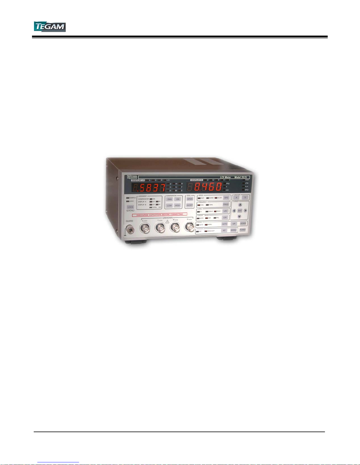
Table of Contents
TEGAM INC.
MODEL 3525
GENERAL-PURPOSE, PROGRAMMABLE
LCR METER
MODEL 3525
Instruction Manual
PN# 3525-900-01CD
Publication Date: February 2009
REV. E
NOTE: This user’s manual was as current as possible when this product was manufactured. However, products are
constantly being updated and improved. Because of this, some differences may occur between the description in this
manual and the product received.
Model 3525 LCR Meter Instruction Manual
a
Page 3

Table of Contents
I INSTRUMENT DESCRIPTION............................................................................1-1
Instrument Description ........................................................................... 1-2
Feature Overview................................................................................... 1-2
Accessories Sheet .................................................................................. 1-4
Performance Specifications...................................................................... 1-5
Measurement Ranges......................................................................... 1-5
Table 1.1 - Absolute Impedance Range Limits Chart...............................1-5
Display A & B – Basic Accuracies ......................................................... 1-6
Table 1.2 – Basic Accuracy for Display A............................................... 1-6
Table 1.3 – Basic Accuracy for Display B............................................... 1-6
Calculating Actual Measurement Accuracies........................................... 1-7
Table 1.4 – Speed Coefficient.............................................................. 1-7
Table 1.5 – Amplitude Coefficient ........................................................ 1-7
Instrument Specifications........................................................................ 1-8
II PREPARATION FOR USE ..................................................................................2-1
Unpacking & Inspection........................................................................... 2-2
Safety Information & Precautions .............................................................2-2
Terms in this Manual ......................................................................... 2-2
Terms as Marked on Equipment........................................................... 2-2
Symbols........................................................................................... 2-3
Grounding the Equipment...................................................................2-3
Danger Arising from the Loss of Ground ............................................... 2-3
Use the Proper Fuse........................................................................... 2-4
Do not Use in Explosive Environments..................................................2-4
Do not Operate without Covers ........................................................... 2-4
Servicing Safety Summary ...................................................................... 2-4
Do not Service Alone ......................................................................... 2-4
Use Care when Servicing with Power On............................................... 2-4
Power Source ................................................................................... 2-4
Line Voltage Selection.............................................................................2-5
Table 2.1 – Operating Voltage Ranges.................................................. 2-5
III QUICK START INSTRUCTIONS.........................................................................3-1
Power the Unit.......................................................................................3-2
Factory Default Settings..........................................................................3-2
Table 3.1 - Factory Default Settings..................................................... 3-2
Instrument Setup...................................................................................3-3
Display A ......................................................................................... 3-3
Display B ......................................................................................... 3-3
Measurement Speed .......................................................................... 3-3
Test Frequency ................................................................................. 3-3
Test Voltage Level............................................................................. 3-3
Circuit Mode ..................................................................................... 3-3
Range.............................................................................................. 3-3
Trigger ............................................................................................ 3-3
Performing an Open and Short Circuit Null................................................. 3-4
Measurement Tips.................................................................................. 3-4
Model 3525 LCR Meter Instruction Manual
b
Page 4

Table of Contents
IV OPERATING INSTRUCTIONS............................................................................4-1
Basic Operation...................................................................................... 4-2
Default Parameters................................................................................. 4-2
Front Panel Description ........................................................................... 4-3
Figure 4.1a – Front Panel Layout ......................................................... 4-3
Figure 4.1b – Measurement & Parameter Control Area............................ 4-4
Figure 4.1c – Comparator Controls Area ............................................... 4-5
Rear Panel Description............................................................................ 4-6
Figure 4.2 – Rear Panel...................................................................... 4-6
Selecting the Measurement Parameters..................................................... 4-7
Table 4.1a – Display A Description of Measurement Functions.................. 4-7
Table 4.1b – Display B Description of Measurement Functions..................4-7
Setting the Measurement Speed...............................................................4-8
Table 4.2 – 3525 Typical Measurement Times........................................4-8
Setting the Measurement Frequency ......................................................... 4-9
Setting the Measurement Signal Level.......................................................4-9
Setting the Equivalent Circuits Mode......................................................... 4-10
Setting the measurement Range .............................................................. 4-11
Table 4.3 – Measurement Range Characteristics .................................... 4-11
Setting the Trigger Mode.........................................................................4-13
Using the Comparator Functions...............................................................4-14
Overview ......................................................................................... 4-14
Table 4.4 – Operation of GO/NO-GO Comparator ................................... 4-14
Setting the High and Low Limit Values.................................................. 4-15
Preset Panel Function..............................................................................4-18
Overview ......................................................................................... 4-18
Setting Panel Numbers....................................................................... 4-18
Recalling Panel Numbers .................................................................... 4-18
Zero Correction...................................................................................... 4-19
Overview ......................................................................................... 4-19
Figure 4.3 – Terminal Connections for Zero Correction............................ 4-19
Open Circuit Correction......................................................................4-20
Short Circuit Correction......................................................................4-20
Audible Beeper ...................................................................................... 4-21
Overview ......................................................................................... 4-21
Setting the Beep Sound...................................................................... 4-21
Connection Methods ............................................................................... 4-22
Figure 4.4 – 3 Terminal Connection...................................................... 4-22
Figure 4.5 – 5 Terminal Connection...................................................... 4-23
V PROGRAMMING & INTERFACING.....................................................................5-1
Interfacing to the 3525 ........................................................................... 5-2
Front Panel Connections..........................................................................5-2
Figure 5.1 – Front Panel Measurement Connections................................ 5-2
Rear Panel ............................................................................................ 5-3
Figure 5.2 – Rear Panel Interfaces....................................................... 5-3
Model 3525 LCR Meter Instruction Manual
c
Page 5

Table of Contents
V PROGRAMMING & INTERFACING cont’d
I/O Control Connector.............................................................................5-4
Compatible Connectors ...................................................................... 5-4
I/O Pin Outputs.................................................................................5-4
Figure 5.3 – I/O Control Connector Pin Orientation................................. 5-4
Table 5.1 – Pin Designations............................................................... 5-5
I/O Pin Descriptions...........................................................................5-5
Table 5.2 – BCD Panel Settings ........................................................... 5-6
Table 5.3 – Total Go & No Go Functional Relationships............................ 5-7
I/O Control Connector Electrical Schematic ........................................... 5-8
Figure 5.4 – I/O Control Connector Schematic....................................... 5-8
I/O Timing Diagrams .............................................................................. 5-9
Figure 5.5 – I/O Control Connector Timing Diagram ............................... 5-9
Approximate Measurement Times............................................................. 5-9
Table 5.4 – Approximate Measurement and Signal Processing Times......... 5-9
Analog Signal Measurement Time ........................................................ 5-10
Table 5.5a – Analog Signal Measurement Time...................................... 5-10
Measurement Speed .......................................................................... 5-10
Table 5.5b – Total Measurement Speed ................................................ 5-10
RS232C Communications ........................................................................ 5-11
Figure 5.6 – RS-232C Connector ......................................................... 5-11
Table 5.6 – RS-232C DTE Pin Configurations......................................... 5-11
RS-232C Settings.............................................................................. 5-12
Remote Commands ................................................................................ 5-13
Program Messages ............................................................................ 5-13
The Header ...................................................................................... 5-13
The Parameter.................................................................................. 5-13
Rules for Remote Commands .............................................................. 5-14
Rules for Commands and Parameters................................................... 5-14
Condition & State Registers ................................................................ 5-15
Commands List.................................................................................5-18
Table 5.7 – RS-232C & GPIB Command Set .......................................... 5-18
Command Reference.......................................................................... 5-19
VI SERVICE INFORMATION..................................................................................6-1
Warranty .............................................................................................. 6-2
Warranty Limitations .............................................................................. 6-2
Statement of Calibration ......................................................................... 6-2
Contact Information ............................................................................... 6-2
Repair Parts .......................................................................................... 6-3
Changing the Power Fuse ........................................................................ 6-3
Preparation for Calibration or Repair Service .............................................. 6-4
Expedite Repair & Calibration Form...................................................... 6-5
Model 3525 Verification Procedure............................................................6-6
VI APPENDIX .......................................................................................................A-1
Model 3525 LCR Meter Instruction Manual
d
Page 6

Instrument Description
INSTRUMENT DESCRIPTION
Model 3525 LCR Meter Instruction Manual
PREPARATION FOR USE
QUICK START INSTRUCTIONS
OPERATING INSTRUCTIONS
PROGRAMMING & INTERFACING
SERVICE INFORMATION
APPENDIX
1-1
Page 7

Model 3525 LCR Meter Instruction Manual Instrument Description
Instrument Description
Model 3525,TEGAM’s innovative solution for cost sensitive LCR applications, does not compromise
quality or performance. Its flexible design allows a diverse range of testing applications including
manual or automated testing of capacitors, inductors, coils, resistors, thermoelectric cooling
devices, materials, piezo-electric or other sensors or components possessing AC impedance
characteristics.
Up to 9 impedance parameters are easily viewed on each of the 3525’s two 4 ½ digit, LED
displays. Display A provides accurate and repeatable readings of Inductance (L), Capacitance (C),
Resistance (R), and Impedance (|Z|). Display B measures values for Dissipation Factor (D or Tan
δ), Quality Factor (Q), Phase Angle (θ), Measurement Voltage (V) and Measurement Current (I).
All parameters are easily monitored, selectable from the front panel, and may be measured as
Series or Parallel equivalent circuits.
The 3525’s compact size is unprecedented and allows side-by-side mounting in standard 19”
racks. A built-in comparator function makes the 3525 the ideal choice for manual component
checking. Whether you are verifying component values for QA or manufacturing, the built in GONO GO comparator reduces test time and increases productivity with an audible beeper that may
be set to alarm when a pass or fail state has been measured. A front panel lock feature prevents
accidental changes on instruments settings.
Model 3525 is shipped from the factory with standard Kelvin Klips, RS-232C port, and I/O
connector. There are a variety of optional accessories available, including GPIB Interface, BCD
Output, Kelvin Klip Leads, Kelvin Tweezers, Radial Sorting Fixture, and SMT Chip Test Fixture. See
the Accessories Sheet on page 1-4 for complete descriptions.
Feature Overview
The Model 3525 was designed with the right balance of features to keep cost down while
providing optimal performance for most basic LCR applications. Below is a summary of the
instrument’s main features.
0.08% Basic Accuracy with 4.5 digit resolution.
The 3525 is designed to perform basic impedance measurements with up to 0.08% basic
accuracy. Measurement accuracies are dependent upon a number of parameters and test
conditions. See Performance Specifications to determine the actual measurement
accuracies.
High Speed Measurement
With a 1kHz test frequency a reading can be obtained in as little as 15 mS when the
instrument is operating in fast mode.
Manual or Remote Operation
The 3525 is equipped for manual or remote operation. Standard interfaces include a RS232C and I/O port. GPIB and BCD interfaces are available as optional accessories.
1-2
Page 8

Model 3525 LCR Meter Instruction Manual Instrument Description
Feature Overview cont’d:
Dual High Intensity Displays
The 3525 is equipped with dual LED displays for easy viewing. Display A measures 4½
digits of Inductance (L), Capacitance (C), Resistance (R), or Impedance (|Z|) while Display
B indicates Dissipation Factor (D or Tan δ), Quality Factor (Q), Phase Angle (θ),
Measurement Voltage (V), or Measurement Current (I).
Programmable GO/NO-GO Comparator with Audible Buzzer
Each unit has an internal comparator function that can be set by the user. Comparator
Outputs result from the values of Display A, Display B, or a combination of the two. The
comparator outputs may be read from the front panel, buzzer, the I/O connector located
on the rear panel, or queried from the remote interfaces.
99 Preset Storage Locations
Panel Settings 01-99 are user-definable and may be programmed manually or via
communication interfaces. These settings are stored in non-volatile RAM locations and may
be recalled from the front panel or any of the rear interfaces.
Less than ½ Rack Width
Two 3525 units are able to be rack mounted, side-by-side, in a standard 19” rack using a
third party rack mount kit, without modifying the instrument cases.
Manual or Auto Ranging
In AUTO range, the instrument automatically selects from 10 different impedance ranges.
The selected range is dependent upon the DUT’s absolute impedance, |Z|. In the manual
range mode, the user may select from any of these ten ranges through the front panel.
Voltage and Current Monitors
Test Voltage (Vx) and Current (Ix) can be measured at the DUT terminals and are
viewable on Display B to three significant digits.
Open and Short Circuit Zero Correction
Parasitic impedance of the test cables and/or test fixture may be cancelled out by
performing the 3525’s auto zero functions.
Front Panel Lock
The 3525 is equipped with a front panel lock-out feature to prevent accidental changes to
instrument settings.
Dual Trigger Modes
Trigger instructions may be executed either internally or externally. Internal triggering
allows the instrument to run continuously while external triggering requires instruction
from the front panel, I/O connector, RS-232C, or GPIB interfaces.
Series or Parallel Equivalent Measurements
AC parameters may be measured as Series or Parallel equivalents.
1-3
Page 9
Model 3525 LCR Meter Instruction Manual Instrument Description
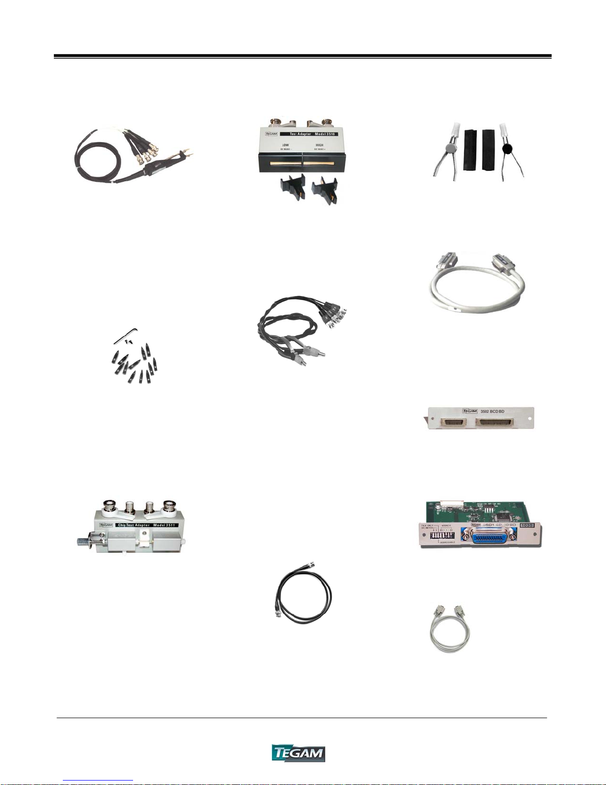
3525 Accessories Sheet
2005B - Chip Tweezers (5ft)
This four-terminal tweezer set
makes solid connections to chip
components in manual sorting
applications. Capacity of jaws is
12.7mm (0.5 in.). The 2005B Chip
Component Tweezer Set includes a
1.5m (5 ft) cable for connection to
the 3525. Contact tips are
replaceable. P/N 47422.
47422 Chip Tweezer
Replacement Kit
Tweezer tips are intended to last
100,000 to 500,000 operations. An
optional tip replacement kit includes
12 replacement tips, 2 screws and 1
wrench.
3511 - Chip Test Fixture
Available for performing three
terminal measurements on surface
mount devices. Connects directly to
the front panel of the 3525. Use the
3511 for medium and high
impedance measurements.
3525-900-01CD – Instruction
Manual
Printed copy of the 3525 users
manual.
1-4
3510-Radial Lead Adapter
This sorting fixture allows for efficient
four-wire measurement of leaded parts.
The test fixture features spring action
contacts for easy insertion and removal of
test components.
47454 – Kelvin Klips
Kelvin Klips allow solid four-terminal,
Kelvin connections to leaded components.
The jaws are assembled with hardened
gold-plated, beryllium copper, which
ensures low contact resistance, low
thermal emf to copper, high corrosion
resistance, and long service life. An
alligator clip is provided allowing
connection of a passive guard. The
assembly includes a 5 ft (1.5m) cable for
connection to the 3525.
NOTE: Under certain measurement conditions,
Kelvin Klips can cause a loss of measurement
accuracy. Fixtures 3510, 3511, or 2005B chip
tweezers are recommended for the following
component values:
C<100pF; L < 100μH; R > 1MΩ
CBL-3102-BNC-BNC Cable
BNC to BNC, RG 58/U, coaxial cable for
use at the trigger inputs and outputs of
the 3525. Cable length is a minimum of 1
meter (3.28 ft) long.
KK100- Kelvin Klip™ Rebuild
Kit
Kelvin Klip™ replacements for
construction or repair of Kelvin Klip
leads.
GPIB (IEEE-488) Cables
1583-3 – 1-meter GPIB buss cable
1583-6 – 2-meter GPIB buss cable
1583-9 – 3-meter GPIB buss cable
3502 – BCD Interface
BCD output for interface to handlers
and other automated systems.
3501 – GPIB Interface
GPIB (IEEE-488)-compatible interface
card. Field or factory installation.
740565 – CABLE NULL
740565-6 – 6’ cable, null mod, 9-9
740565-10 – 10’ cable, null mod, 9-9
Page 10
Model 3525 LCR Meter Instruction Manual Instrument Description
Performance Specifications
The advertised specifications of the Model 3525 are valid under the following conditions:
1. The instrument’s calibration must be verified using the methods and intervals as described
in the Service Information Section of this user’s manual.
2. The instrument must be in an environment which does not exceed the limitations as
defined under “Environmental” in the Instrument Specifications section.
3. The unit is allowed to warm up for a period of at least 30 minutes before measurements
are taken. A warm-up period of 60 minutes is recommended after exposure to or storage
in a high humidity, non-condensing environment.
4. Use only TEGAM-manufactured test leads and sorting fixtures with this device. Modification
of existing test cables or fixtures may compromise the accuracy of your readings. Always
perform an open and short zero null procedure before taking measurements.
Measurement Ranges
Table 1.1: Absolute Impedance Range Limits Chart
Range No. |Z| Measurement Range
1 0.0100Ω ~ 0.1999Ω
2 0.1800Ω ~1.9999Ω
3 1.800Ω ~ 19.999Ω
4 20.00Ω ~ 199.99Ω
5 0.2000kΩ ~ 1.9999kΩ
6 2.000kΩ ~ 19.999kΩ
7 20.00kΩ ~ 199.99kΩ
8 0.1800MΩ ~ 1.9999MΩ
9 2.000MΩ ~ 19.999MΩ
10 18.0MΩ ~ 199.99MΩ
The measurement range is determined by the absolute impedance, |Z| of the DUT. The absolute
impedance includes the vector sum of L, C, and R values.
1-5
Page 11
Model 3525 LCR Meter Instruction Manual Instrument Description
Display A & B - Basic Accuracies
Table 1.2: Basic Accuracy for Display A
Range L C R Z
1 ±(0.90+30/fL1)% ±(0.60+1.5fC1)% ±(1.00+0.21/R1)% ±(1.00+0.15/Z1)%
2 ±2.10% ±2.10% ±2.10% ±1.80%
3 ±0.39% ±0.39% ±0.39% ±0.35%
4 ±0.10% ±0.10% ±0.10% ±0.08%
5 ±0.09% ±0.09% ±0.09% ±0.08%
6 ±0.13% ±0.13% ±0.13% ±0.11%
7 ±0.16% ±0.16% ±0.16% ±0.14%
8 ±0.34% ±0.34% ±0.34% ±0.30%
9 ±(0.17+1.17fL2)% ±(0.17+30/fC2)% ±(0.15+0.20R2)% ±(0.15+0.16Z2)%
10 ±(2.00+1.00fL2)% ±(1.7+30/fC2)% ±(2.00+0.16R2)% ±(2.00+0.11Z2)%
Table 1.3: Basic Accuracy for Display B
Range D θ
1 ±(0.002+0.0015/Z1) ±(0.10+0.09/Z1)°
2 ±0.0179 ±1.00°
3 ±0.0034 ±0.18°
4 ±0.0016 ±0.08°
5 ±0.0011 ±0.05°
6 ±0.0016 ±0.08°
7 ±0.0020 ±0.10°
8 ±0.0036 ±0.19°
9 ±(0.002+0.0015Z2) ±(0.10+0.09Z2)°
10 ±(0.012+0.0014Z2) ±(0.70+0.08Z2)°
IMPORTANT ACCURACY NOTES:
Basic Precision Test Conditions:
• Measurement Speed: SLOW
• Measurement Signal Level: 1V
• Open and Closed Circuit Zero Correction
Performed
Units:
• Z
- DUT absolute impedance [Ω]
1
• Z
- DUT absolute impedance [MΩ]
2
• C
- Capacitance [mF]
1
• C
- Capacitance [pF]
2
• L
- Inductance [μH]
1
• L
- Inductance [kH]
2
• f - Test Frequency [kHz]
Other Conditions
• Q – Quality factor based on 1/D
• C - Accuracy is for when D≤0.1
• L - Accuracy is for when D≤0.1
• R - Accuracy is for when θ≤6°
The basic accuracy formulas in Tables 1.2 & 1.3 are based on the assumption that the
measurement speed is Slow, and the measurement signal level is 1V. The exact accuracies will
vary according to the measurement speed and measurement signal level. The formula for
calculating the exact measurement accuracy is found in the next section:
1-6
Page 12
Model 3525 LCR Meter Instruction Manual Instrument Description
Calculating Actual Measurement Accuracies
NOTE: All measurement accuracies assume that open and short circuit zero corrections have
been performed.
Measurement Accuracy = Basic Accuracy X Speed Coefficient X Level Coefficient + 2 Counts
Table 1.4: Speed Coefficient
FAST NORM SLOW
Speed Coefficient
Table 1.5: Amplitude Coefficient
1V 500mV 50mV
Amplitude Coefficient 1 1.5 2
NOTE: The 3525 will produce a reading in both range 1 and range 10 using a 50mV test voltage. These
readings are for reference use only and are not within any specified accuracy limits.
When measuring C and L, if the condition D≤0.1 is not satisfied, use Z and θ for accuracy
calculations.
See below for an example calculation of this condition:
< Using Z and θ for accuracy calculation >
When C=20nF, D=0.5, Measurement Frequency = 1kHz, Signal Level = 1V, and Measurement
Speed is SLOW:
1. Solve for Z and θ (The |Z| or θ measured values of the 3525 can also be used.)
θ=tan-1 (1/D)=63.43°
Z=(1/ωC)×(1/sinθ)=8.897kΩ
2. Find the accuracy value using the charts for Z and θ
From Z, the measurement range will be range 6. In range 6, the accuracy of
Z =±0.11%, and the accuracy of θ =±0.08°.
From this accuracy, the maximum and minimum values of Z and θ should be
calculated.
: 8.907kΩ Z
Z
max
: 63.51° θ
θ
max
min
min
3. From the max and min values, find the range of C and D.
= 1/(Z
C
max
C
= 1/(Z
min
D
= 1/tan θ
max
= 1/tan θ
D
min
×ω×sinθ
min
×ω×sinθ
max
= 0.5017 (0.0017)
min
= 0.4983 (-0.0017)
max
4. The Accuracy of C =±0.18%, D=±0.0017
3 1.5 1
: 8.887kΩ
: 63.35°
) = 2.0036nF (+0.18%)
min
) = 1.9964nF (-0.18%)
max
1-7
Page 13

Model 3525 LCR Meter Instruction Manual Instrument Description
Instrument Specifications
Measurement Parameters
• L (Inductance)
• C (Capacitance)
• R (Resistance)
• |Z| (Impedance)
• D (Dissipation Factor / Tan δ)
• Q (Quality Factor)
• θ (Phase Angle in Degrees)
• V (Inter-Terminal Voltage)
• I (Inter-Terminal Current)
Measurement Range
• L 1.6000uH ~ 199.99kH
• C 0.9400pF ~ 199.99mF
• R 0.0100 ~ 199.99MΩ
• |Z| 0.0100 ~ 199.99MΩ
• D 0.0001 ~ 19.999
• Q 0.5 ~ 199.99
• θ –180.00 ~ 180.00°
• V 0.00V ~ 1.00V
• I 0.00mA ~ 10.00mA
Basic Precision
• 0.08% (See Measurement Range and Precision for Exact Accuracies)
Measurement Frequency
• 1kHz, 120Hz (Frequency Precision: ±0.01% or less)
Output Impedance
• 100Ω ±10Ω
Measurement Signal Level
• 50mV, 500mV, 1V (Setting Accuracy: ±10%±10mV)
Maximum Short-Circuit Current
• 10mA
Measurement Ranges
• The measurement range is based on the value of |Z|. Parameters other than |Z|, such as L, C, R, D, Q, & θ are
calculable values.
• There are ten ranges from 0.1Ω ~ 100MΩ
• Auto or Manual Range Modes
Equivalent Circuit Modes
• Auto or Manually selected Parallel or Series Equivalent Circuit Measurement Modes
1-8
Page 14

Model 3525 LCR Meter Instruction Manual Instrument Description
Instrument Specifications cont’d:
Displays A & B
• 4½ Digit, High Visibility LED Displays
Measurement & Measurement Speed
• Measured parameter values are determined by the voltage and current amplitudes & phases detected by the
instrument’s circuitry and/or the average of calculated values.
• Total measurement times are dependent on the measurement frequency, integration speed, comparator settings
and correction factor values.
• There are three user-selectable integration speeds to choose from. These are Fast, Normal, and Slow.
Typical Measurement Times:
MODE
MEASUREMENT
FREQUENCY
FAST
NORMAL
SLOW
Trigger Functions
• Internal Trigger – Instrument runs in continuous mode.
• External Trigger – Executed by the front panel push button, I/O connector TTL input, RS-232C, or GPIB
commands
Measurement Terminal
• 5-Terminal (BNC with Guard) Kelvin Configuration
Auto Zero Correction
• Open Circuit Correction ≥1kΩ
• Short Circuit Correction ≤ 1kΩ
Absolute Comparator
Functions
• Display A
• Display B
• Display A & Display B
Output
s
• Front Panel LED
• Audible Buzzer
• External I/O Connector (HI,LO,GO,TOTAL GO,BUSY,END)
• RS-232C or GPIB Interface
Front Panel Settings
• Up to 99 user-definable front panel settings
• System Reset – Initializes the instrument to factory default settings
120 Hz 1kHz
40mS
90mS
360mS
15mS
50mS
250mS
1-9
Page 15

Model 3525 LCR Meter Instruction Manual Instrument Description
Instrument Specifications cont’d:
Key Lock Function
• Disables all front panel keys except the manual trigger key.
Audible Buzzer
• User selectable to GO, NO-GO, or OFF operation
Remote Interface
• Control I/O Connector (TTL Open Collector; Optically Isolated) – Standard Accessory
• RS-232C Interface – Standard Accessory
• GPIB Interface – Optional Accessory
• BCD Interface – Optional Accessory
Environmental
• Operating Conditions: from 32° to 104°F (0° to 40°C), <80% RH; (Non-Condensing)
NOTE: Accuracy errors will double when the unit is operated outside of the specified environmental conditions.
• Storage Conditions: from 14° to 131°F (–10° to 55°C), <80% RH; (Non-Condensing)
AC Power Requirements:
• 100/120/220/240 VAC ± 10%; 50/60 Hz
• 20VA ±10%
Fuse:
• For 100/120 VAC Operation; Use 1A @ 250V, fast acting, TEGAM PN#FU-3102-220
• For 220/240 VAC Operation; Use ½A @ 250V, fast acting, TEGAM PN#49743
3525 Dimensions:
• Depth: 6.69” (17.0 cm)
• Width: 7.87” (20.0 cm)
• Height: 3.94” (10.0 cm)
Weight:
• 5.51 lb (2.5kg)
Standard Accessories:
• Users Manual CD Version – PN# 3525-900-01CD
• Standard AC Power Cord – PN#161006600
• Kelvin Klips - PN#47454
Optional Accessories:
• Radial Lead Adapter – PN#3510
• Chip Tweezers – PN#2005B
• Chip Test Fixture – PN#3511
• BCD Interface – PN#3502
• GPIB (IEEE-488 Interface) – PN#3501
1-10
Page 16

Preparation for Use
INSTRUMENT DESCRIPTION
PREPARATION FOR USE
QUICK START INSTRUCTIONS
OPERATING INSTRUCTIONS
PROGRAMMING & INTERFACING
SERVICE INFORMATION
APPENDIX
Model 3525 LCR Meter Instruction Manual 2-1
Page 17

Model 3525 LCR Meter Instruction Manual Preparation for Use
Unpacking & Inspection:
Each 3525 is put through a series of electrical and mechanical inspections before shipment to the
customer. Upon receipt of your instrument, unpack all of the items from the shipping carton and
inspect, them for any damage that may have occurred during transit. Report any damaged items
to the shipping agent. Retain and use the original packing materia l f o r reshipment if necessary.
Upon receipt, inspect the carton for the following items:
Model 3525 General Purpose, Programmable LCR Meter
Model 3525 User’s Manual CD
Kelvin Klips™ PN#47454
!
Safety Information & Precautions:
The following safety information applies to both operation and service personnel. Safety
precautions and warnings may be found throughout this instruction manual and on the equipment.
These warnings may be in the form of a symbol or a written statement. Below is a summary of
these precautions.
Terms in This Manual:
CAUTION statements identify conditions or practices that could result in damage to the equipment
or other property.
WARNING
life.
statements apply conditions or practices that could result in personal injury or loss of
Terms as Marked on Equipment:
CAUTION indicates a personal injury hazard not immediately accessible as one reads the marking,
or a hazard to property including the equipment itself.
DANGER
indicates a personal injury hazard immediately accessible as one reads the marking.
2-2
Page 18
Model 3525 LCR Meter Instruction Manual Preparation for Use
!
Safety Information & Precautions Cont’d:
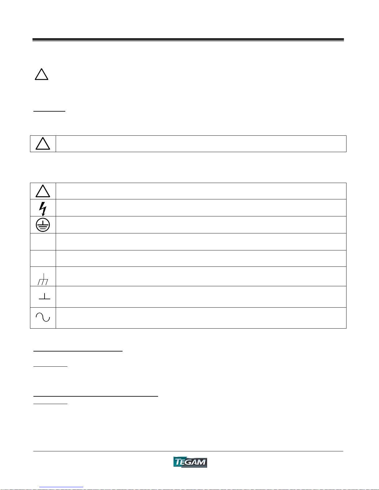
Symbols:
As Marked in This Manual:
!
This symbol denotes where precautionary information may be found.
As Marked on Equipment:
!
CAUTION – Risk of Danger
DANGER – Risk of Electric Shock
Earth Ground Terminal
l
O
On
Off
Frame or Chassis Terminal
Earth Ground Terminal
Alternating Current
Grounding the Equipment
This product is grounded through the grounding conductor of the power cord.
WARNING:
properly wired receptacle before using this instrument. The proper grounding of this instrument is
essential for safety and optimizing instrument operation.
Danger Arising from Loss of Ground
WARNING:
in the instrument. Under these conditions all accessible parts, including insulating parts such as
keypads and buttons, could develop a hazardous voltage and put the user at risk.
To avoid electrical shock or other potential safety hazards, plug the power cord into a
If the connection to ground is lost or compromised, a floating potential could develop
2-3
Page 19

Model 3525 LCR Meter Instruction Manual Preparation for Use
!
Use the Proper Fuse
To avoid fire hazard, use only the correct fuse type as specified for the AC power supply in the
“Instrument Description” or “Service Information” sections of this manual. Please note that the
fuse rating for 100/120-volt operation is different than the rating for 200/240-volt operation.
Information about the proper fuse type is also printed on the rear panel of the instrument.
Refer fuse replacement to qualified service personnel.
Do Not Use in Explosive Environments
WARNING:
Do not Operate Without Covers
WARNING:
missing panels or covers could result in personal injury.
The 3525 is not designed for operation in explosive environments.
This device should be operated with all panels and covers in place. Operation with
FOR QUALIFIED SERVICE PERSONNEL ONLY
Servicing Safety Summary:
!
Do Not Service Alone
Do not perform service or adjustment on this product unless another person capable of rendering
first aid is present.
Use Care When Servicing with Power On or Off
Dangerous voltages may exist at several points in this product. To avoid personal injury or
damage to this equipment, avoid touching exposed connections or components while the power is
on. Assure that the power is off by unplugging the instrument when removing panels, soldering, or
replacing components.
WARNING:
present throughout the instrument even when the instrument is in the OFF state.
Always unplug the instrument and wait 5 minutes before accessing internal components.
Power Source
This product is intended to connect to a power source that will not apply more than 250V RMS
between the supply conductors or between either supply conductor and ground. A protective
ground connection by way of the grounding conductor in the power cord is essential for safe
operation.
The instrument power source is electronically con trolled, meaning that there is power
2-4
Page 20
Model 3525 LCR Meter Instruction Manual Preparation for Use
Line Voltage Selection:
!
CAUTION: DO NOT APPLY POWER TO THE INSTRUMENT BEFORE READING THIS SECTION:
Unless otherwise specified, the Model 3525 is delivered from TEGAM with its power supply set for
120V, 60 Hz operation. However, the 3525 design allows it to operate under 100/120/220/240V
@ 50/60 operation. It is strongly recommended that the line voltage, frequency setting, and fuse
type be verified before powering the unit.
First, determine the operating voltage that the instrument will be supplied. Also, verify that the
supply voltage does not fall outside of the allowable ranges in the table below:
Table 2.1 – Operating Voltage Ranges
Switch Position Voltage Range
100 90V ~ 110V
120 108V ~ 132V
220 198V ~ 242V
240 216V ~ 250V
The following procedure describes the steps necessary to change the 3525 power settings from
factory default settings to a new setting.
1. Verify that there is no power connected to the unit.
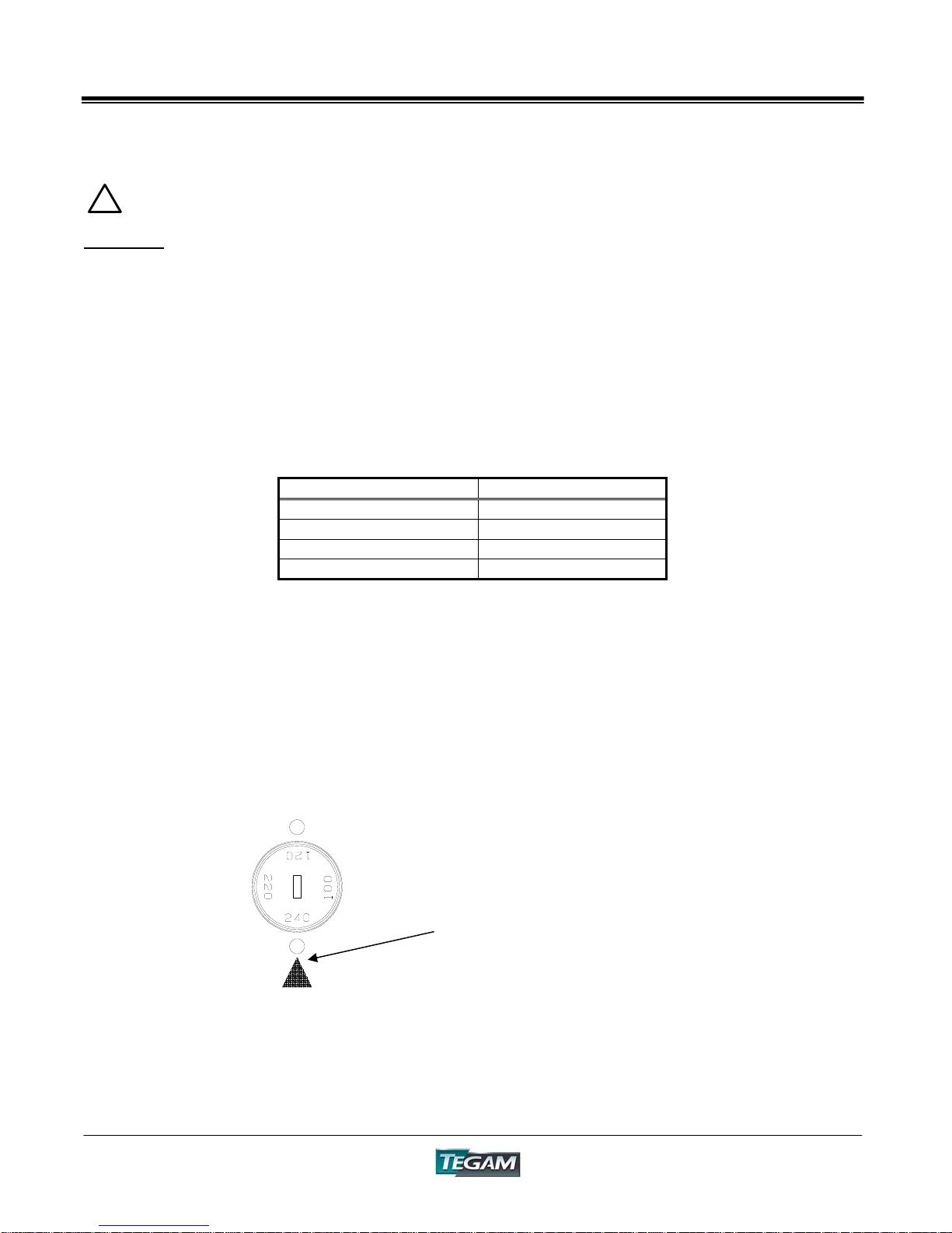
2. Change the line selector switch located on the rear panel of the 3525 to the desired
operating voltage by using a small screwdriver to turn the voltage selection switch to the
desired position.
Refer to the figure below:
With your screwdriver, turn the
desired voltage number to the black
arrow. For example, the setting
here is for 240V.
3. The fuse size may need to be changed as a result of the increased or decreased voltage
operation. Please refer to the “Service Information” section of this manual (page 6-3) for
detailed fuse information. The rear panel of the 3525 will also contain information
regarding fuse sizes and types.
2-5
Page 21

Quick Start Instructions
INSTRUMENT DESCRIPTION
PREPARATION FOR USE
QUICK START INSTRUCTIONS
OPERATING INSTRUCTIONS
PROGRAMMING & INTERFACING
SERVICE INFORMATION
APPENDIX
Model 3525 LCR Meter Instruction Manual 3-1
Page 22
Model 3525 LCR Meter Instruction Manual Quick Start Instructions
Proper use of the Model 3525 will maximize measurement accuracy and productivity. The Quick
Start section is designed to provide speedy setup for general-purpose applications. It is highly
recommended that the user read Chapter 4 for applications involving high accuracy or requiring
optimal performance of the instrument.
Power the Unit
!
CAUTION
The power supply of the Model 3525 is designed for 50-60 Hz operation and a voltage range of
100-240 VAC. Review the line voltage selection procedure on page 2-5 before proceeding. Make
sure that the line voltage setting matches the supply voltage and frequency.
Power the unit and allow at least 30 minutes for the unit to warm up. Make sure that the safety
precautions on pages 2-3 and 2-4 have been reviewed and understood. Verify that the
environmental conditions, listed on pages 1-10, are met.
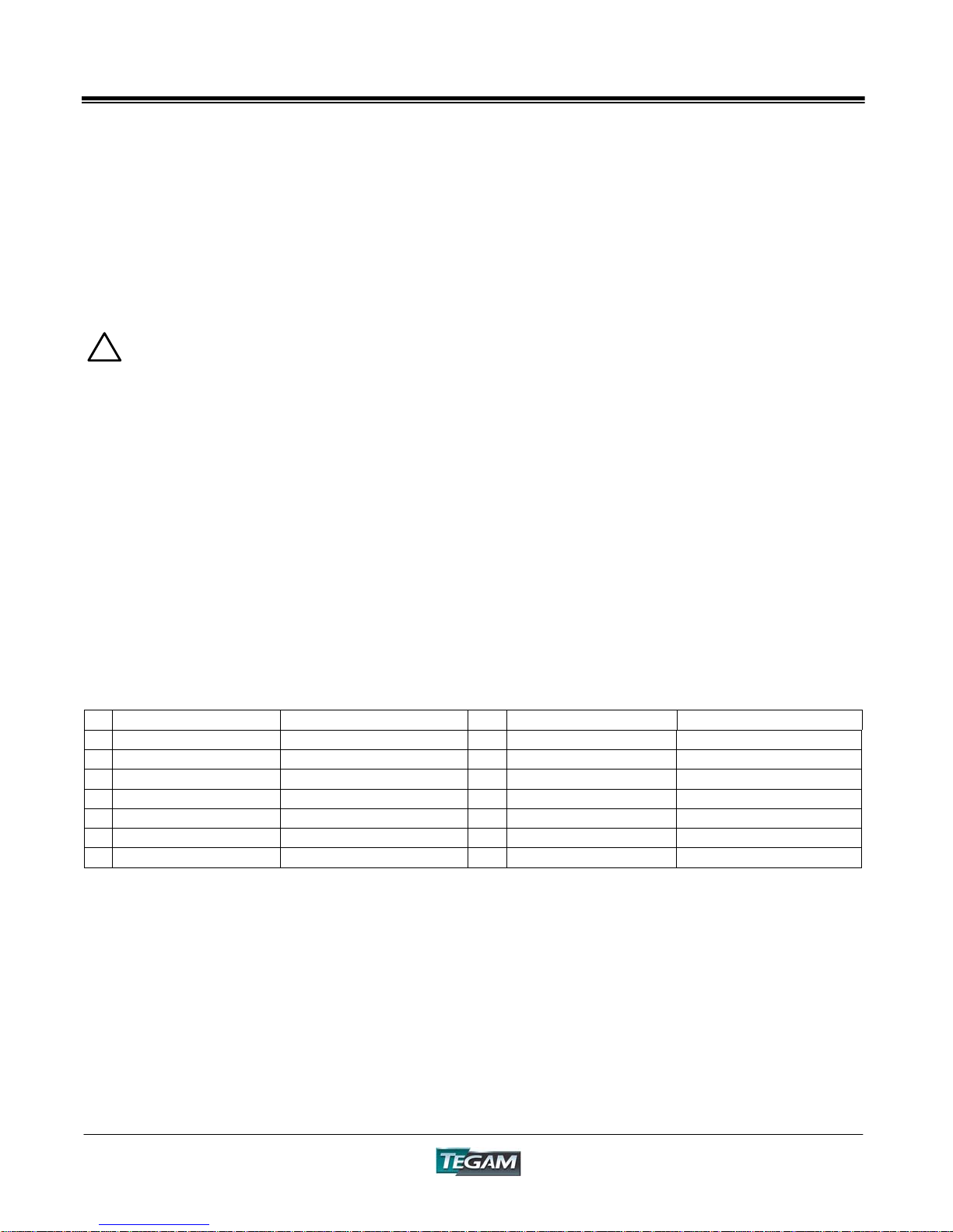
Factory Default Settings
The 3525 is shipped from the factory with instrument settings as follows:
Table 3.1 – Factory Default Settings
Parameter Setting Parameter Setting
1 Range AUTO 8 Communication *RS232 or GPIB
2 Trigger Internal 9 Key Lock UN-LOCKED
3 Speed FAST 10
4 Display A Capacitance 11
5 Display B Dissipation Factor 12
6 Trigger Internal 13
7 Range Auto 14
* When a device clear command is sent via communications interface, this value does not change.
These settings can be recalled by sending a device clear command, *RST via RS232, or GPIB
interface.
NOTE: When the 3525’s power is cycled, the instrument’s settings will return to the state that
existed at the time the power was last turned off. You can initialize the 3525 to factory default
settings by pressing the [MANU] key while powering the unit.
Comparator/Buzzer OFF
Frequency 1kHz
Voltage Level 1V
Circuit Mode AUTO
Manual/Remote Remote
3-2
Page 23

Model 3525 LCR Meter Instruction Manual
Quick Start Instructions
Instrument Setup
Setup of the Model 3525 for general-purpose use is easy. Once the unit has been allowed to warm
up, review the front panel and note the changes that need to be made in order to perform your
required measurements. Below are Quick Setup instructions to adjust the main measurement
parameters of the 3525. Refer to Chapter IV, Operating Instructions, for a comprehensive
description of all the measurement options and instrument settings, including the ones listed
below:
Display A
To select L, C, R or |Z| value to be indicated on Display A, make sure that the comparator function
is disabled by pressing the [ON] key until all of the LED’s in the JUDGMENT field are off. In the
FUNCTION field, press the [A] key until the desired parameter’s annunciator is lit.
Display B
To select D, Q, θ, V or I value to be indicated on Display B, make sure that the comparator
function is disabled by pressing the [ON] key until all of the LED’s in the JUDGMENT field are off.
In the FUNCTION field, press the [B] key until the desired parameter’s annunciator is lit.
Measurement Speed
In order to select FAST, NORMAL, OR SLOW mode, press the [SPD] key until the desired
measurement rate is illuminated.
Test Frequency
In order to choose a 1kHz or 120 Hz test frequency, press the [FREQ] key until the desired
frequency LED is illuminated.
Test Voltage Level
Select either 1V, 500mV, or 50 mV test voltage by pressing the [LEV] key until the desired voltage
is selected.
Circuit Mode
The default equivalent circuit mode is AUTO. Refer to Chapter IV for information on series or
parallel equivalent circuit measurements.
Range
The default range setting is AUTO. Refer to Chapter IV for more information on manual range
selection.
Trigger
Press the [INT] key to select internal (continuous) triggering mode. Press the [MANU] key to
select manual or external triggering options. Trigger the unit from the front panel by pressing the
[MANU] key.
3-3
Page 24

Model 3525 LCR Meter Instruction Manual Quick Start Instructions
Performing an Open and Short Circuit Null
Once you have verified that all of the instrument settings are correct, the next step is to perform a
zero correction.
1. Assuming that Kelvin Klip™ leads are being used, orient the leads in a similar position that
they will be connected to the DUT. Open the leads (refer to page 4-19 for proper lead
orientation.)
2. Press the [OPEN] key in the Zero field of the front panel. Allow the unit to step through the
open circuit null procedure.
3. Then short the Kelvin Klip™ leads together. Press the [SHORT] key and allow the
instrument to step through the short zero adjustment.
You have completed the Zero Correction procedure and are now ready to take basic impedance
measurements. Refer to Chapter IV, Operating instructions for additional details or information
regarding the use of this instrument.
Measurement Tips
Here are some general tips for users who are relatively new to performing LCR measurements:
• Unless otherwise specified, use 120Hz for capacitance measurements and use 1kHz for
testing inductors.
• The 3525 will take the most accurate reading at SLOW measurement speed and 1V test
voltage level.
• Orientation of test leads is important for repeatable measurements especially at high
frequencies. Try to keep lead orientation the same when making precision measurements.
• Keep metallic or other objects away from test leads including hands when performing zero
correction or impedance measurements.
• When measuring components with values that fall to the outer limits or outside of a
particular range, put the instrument in manual range to eliminate range switching by
locking into one range. This increases repeatability and measurement accuracy.
• When testing capacitors, make sure that the capacitor is completely discharged before
connection to the measurement terminals of the 3525.
• Use the Guard Terminal for high impedance measurements to minimize leakage errors and
noise.
3-4
Page 25

Operating Instructions
INSTRUMENT DESCRIPTION
PREPARATION FOR USE
QUICK START INSTRUCTIONS
OPERATING INSTRUCTIONS
PROGRAMMING & INTERFACING
SERVICE INFORMATION
APPENDIX
Model 3525 LCR Meter Instruction Manual 4-1
Page 26

Model 3525 LCR Meter Instruction Manual Operating Instructions
Please read and understand Chapter III, Quick Start Instructions before proceeding
with this section.
Basic Operation
The Model 3525 is a highly versatile product, designed for use in many different applications.
There are ideal configurations of the 3525 for each measurement application. These configurations
optimize accuracy, measurement speed, and flexibility.
This section is designed to give the user a comprehensive description of the parameters and
operating modes available from the Model 3525. The user will be exposed to additional topics that
will enhance the integration of the Model 3525 into their application.
It is highly recommended that the user read this section thoroughly if the intended application
requires high precision and maximum throughput.
Default Parameters
Model 3525 is shipped from TEGAM fully calibrated, tested, and preset to factory default settings
to accommodate general-purpose manual operation. Chapter III, Quick Start Instructions, contains
specific information about factory default settings and some general tips for new users. Please
read and understand Chapter III, Quick Start Instructions, before proceeding.
4-2
Page 27
Model 3525 LCR Meter Instruction Manual Operating Instructions
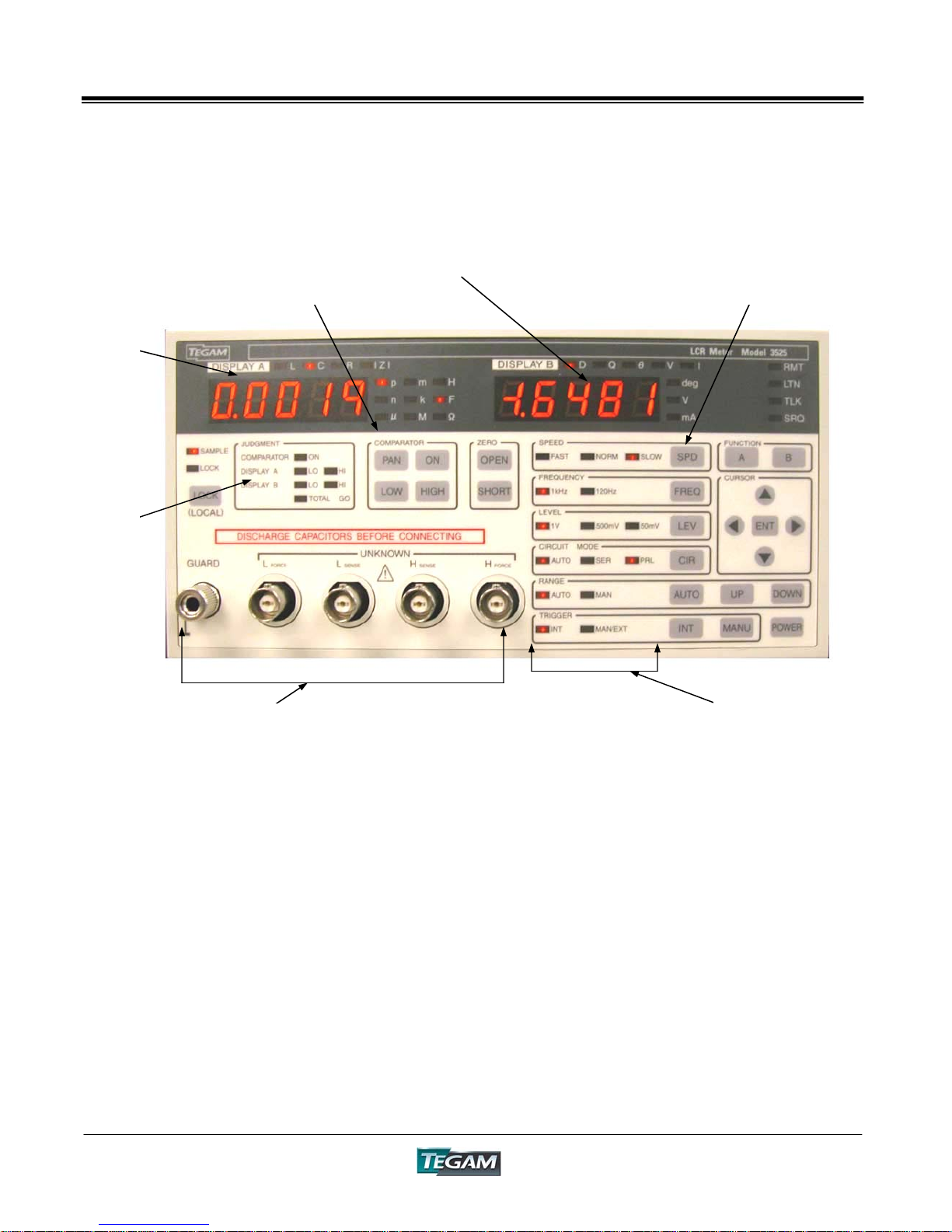
Front Panel Description
Figure 4.1a: Front Panel Layout
DISPLAY A
COMPARATOR
STATUS
DISPLAY
COMPARATOR
OPERATIONS PANEL
MEASUREMENT TERMINALS
DISPLAY B
PARAMETER
SELECTION KEYS
PARAMETER MODE
INDICATORS
DISPLAY A
4-1/2 Digit LED Display indicates measured
values for L, C, R, and |Z|.
DISPLAY B
4-1/2 Digit LED Display indicates measured
values for D, Q, θ, V, and I.
Parameter Mode Indicators
Displays active parameter modes and settings.
Comparator Status Display
Displays judgment results for display A, Display
B or both. Results are based on comparator
settings and measurement results.
Parameter Selection & Control Keys
Use these keys for selecting measurement
modes and parameters.
Comparator Operations Panel
Used for enabling the comparator, programming
high and low limits and for preset panel selection.
Measurement Terminals:
A 5-terminal scheme is used:
HFORCE – High potential terminal for sourcing
measurement current.
HSENSE - The "high" terminal for voltage sensing.
LSENSE - The "low" terminal for voltage or sensing
LFORCE - Low potential terminal for sourcing
measurement current.
GUARD - The guard terminal. Use this connection
to cancel any stray capacitance and conductance
associated with high impedance measurements.
4-3
Page 28
Model 3525 LCR Meter Instruction Manual Operating Instructions
R
R
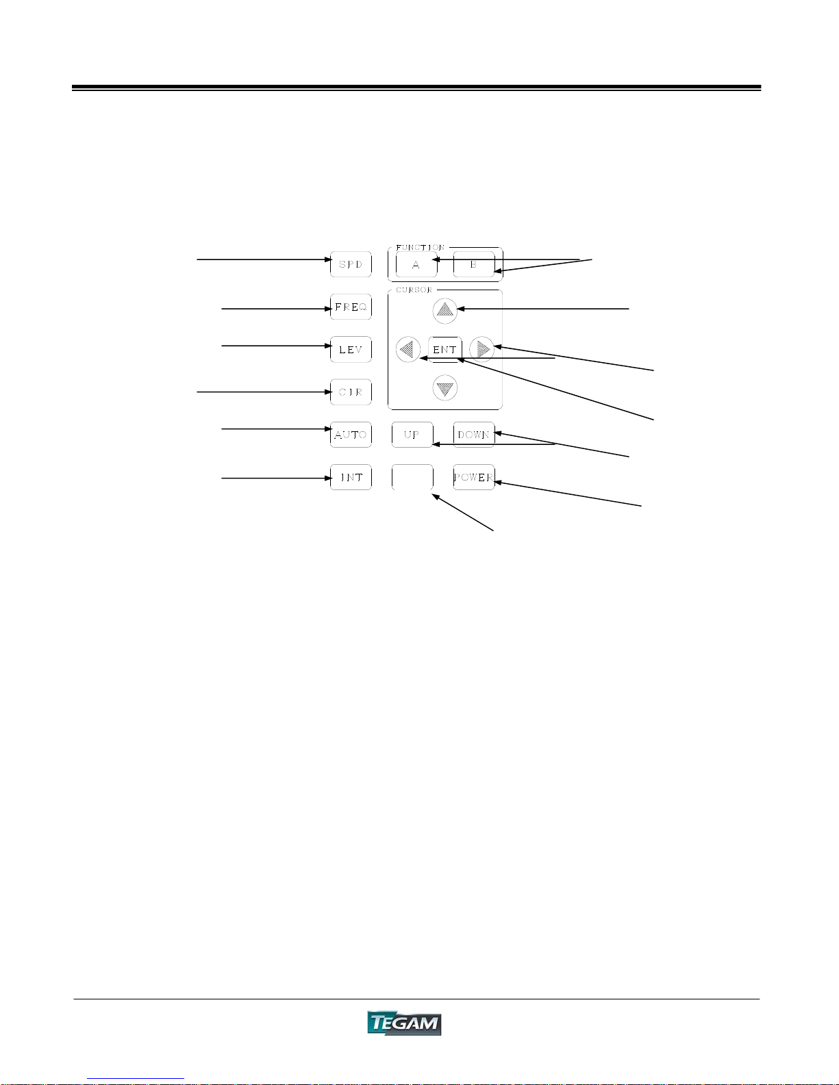
Front Panel Description cont’d:
Figure 4.1b: Measurement & Parameter Control Area
MEASUREMENT
SPEED
DISPLAY A OR B
PARAMETER SELECTION
TEST FREQUENCY
COUNT SETTING
Measurement Speed Key
Use this key to select either FAST, NORMAL, or SLOW
measurement speed.
Test Frequency Key
Use this key to select either 120Hz or 1kHz
measurement frequency.
Measurement Signal Level Key
Press this key to select 1V, 500mV, or 50mV test
signal amplitude.
Equivalent Circuits Mode Key
Press this key to select Series, Parallel, or AUTO
equivalent circuit measurements.
Range Mode Key
Press the AUTO key to toggle between AUTO and
Manual ranging modes.
Internal Trigger Key
Press this key to select continuous internal triggering
of the instrument.
Manual Trigger Key
Press the manual trigger key to select manual or
external triggering from the front panel or remote
interface. Consequent pressing of the [MANU] key
will trigger the instrument.
MEASUREMENT SIGNAL
AMPLITUDE LEVEL
EQUIVALENT
MEASURMENT
CIRCUIT
AUTO OR MANUAL
RANGE
INTERNAL TRIGGER
CURSO
POSITIONING
ENTER KEY
ANGE UP/DOWN
MANU
EXTERNAL TRIGGER SELECTION
MANUAL TRIGGER AND
SELECTION
POWER ON/OFF
DISPLAY A Selection Key
Press [A] to select the active measurement
parameter for Display A.
DISPLAY B Selection Key
Press [B] to select the active measurement
parameter for Display B.
Count Setting Keys
Pressing the [▲] or [▼] keys allows the user to
change count, decimal place or units settings during
comparator setup.
Cursor Positioning Keys
The [►] or [◄] key allows movement of the display
cursor when programming comparator settings.
Enter Key
Enters new parameters or modes into instrument
memory.
Range Down key
In manual range mode, this key decrements the
active measurement range number.
Range Up Key
In manual range mode, this key increments the
active measurement range number.
Power Switch
Toggles the unit power either on or off.
4-4
Page 29
Model 3525 LCR Meter Instruction Manual Operating Instructions
T
T
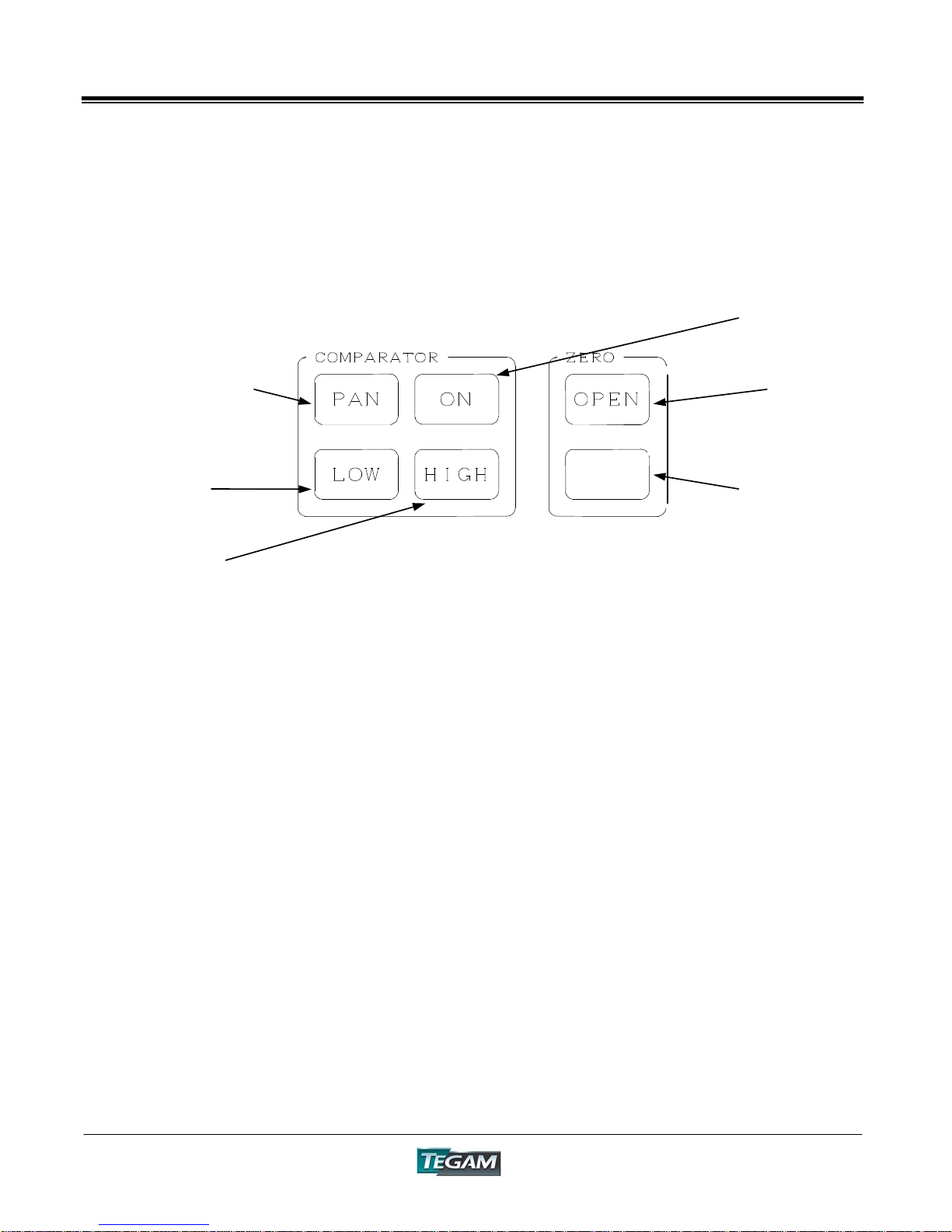
Front Panel Description cont’d:
Figure 4.1c: Comparator Controls Area
PANEL SELECTION
COMPARATOR LOW
LIMIT
COMPARATOR
HIGH LIMIT
Panel Selection
Use this key to recall panel presets from 00-99
Comparator Low Limit
Press this key to access the comparator low limit
programming mode.
Comparator High Limit
Press this key to access the comparator high limit
programming mode.
SHORT
Comparator ON/OFF
Pressing this key will either enable or disable
comparator operation.
Open Circuit Null
With the test leads open, pressing this key will
initiate the open circuit zeroing process.
Short Circuit Null
With the test leads shorted, pressing this key will
initiate the short circuit zeroing process.
COMPARATOR
ON/OFF
OPEN CIRCUI
NULL
SHORT CIRCUI
NULL
4-5
Page 30

Model 3525 LCR Meter Instruction Manual Operating Instructions
Rear Panel Description:
Figure 4.2: Rear Panel
Voltage
Selection Dial
Power & Fuse
Socket
Options Panel
Cover
Serial Number
Control I/O
Connector
RS232C
Connector
Voltage Selection Dial
For selection of proper operating voltage see
Chapter II, Preparation for Use.
Power & Fuse Socket
The three-conductor power cord plugs into this
socket. The line fuse is also accessible here.
Serial Number
The Product Serial Number is located here.
Options Panel Cover
Blank cover for Units without GPIB
communications or BCD options. This is where
the options are installed.
Control I/O Connector
TTL control signal output connector. Photo
isolated.
RS232C Connector
RS232C interface connector.
4-6
Page 31

Model 3525 LCR Meter Instruction Manual Operating Instructions
Selecting the Measurement Parameters
On the 3525, you are able to set the measurement parameters on DISPLAY A and DISPLAY B
independently. The tables below summarize the measurement options available from DISPLAY A
and DISPLAY B.
Table 4.1a: DISPLAY A – Description of Measurement Functions
Item Description
L Measures the inductance of the DUT
C Measures the capacitance of the DUT
R Measures the resistance of the DUT
|Z|
Table 4.1b: DISPLAY B – Description of Measurement Functions
Item Description
D
Q Measures the quality factor of the DUT
θ Measures the phase angle of the DUT
V
I
The measurement parameter for display A is selected simply by repeatedly pressing the [A] key
until the desired measurement parameter LED lights. The sequence of measurement parameters is
as follows:
An illuminated LED indicates the active measurement parameter for DISPLAY A:
Measures the absolute value of impedance
of the DUT
Measures the Dissipation Factor, (loss
coefficient or tan δ) of the DUT
Measures the test voltage between
measurement terminals
Measures the test current through
measurement terminals
L→C→R→|Z|→L …
4-7
Page 32

Model 3525 LCR Meter Instruction Manual Operating Instructions
Selecting the Measurement Parameters cont’d:
The measurement parameter on DISPLAY B will change sequentially as the [B] key is pressed:
D→Q→θ→V→I….
Select the desired measurement parameter. Like in DISPLAY A, the active parameter LED will be
lit above DISPLAY B.
Setting the Measurement Speed
The 3525 has three measurement speeds to choose from. These are FAST, NORMAL, and SLOW.
The most accurate readings are obtained in the SLOW measurement mode.
The measurement frequency and the measurement mode are the key variables, which affect total
measurement time. Their typical relationship to measurement speed is indicated in the table
below.
Table 4.2: 3525 Typical Measurement Times
Measurement
Frequency
1kHz 15ms 50ms 250ms
120Hz 40ms 90ms 360ms
To set the measurement speed, press [SPD] until the desired mode is illuminated. The active
mode will change sequentially as the [SPD] key is pressed.
FAST→NORM→SLOW→FAST…
FAST NORMAL SLOW
4-8
Page 33

Model 3525 LCR Meter Instruction Manual Operating Instructions
Setting the Measurement Frequency
On the 3525, you can select between two measurement frequencies: 1kHz and 120Hz.
To select the measurement frequency, press the [FREQ] key to scroll through the frequency
options:
1kHz→120Hz→1kHz….
When the desired frequency has been selected, you can confirm you selection by inspecting the
frequency LED located to the left of the [FREQ] key.
Setting the Measurement Signal Level
The 3525 has three selectable signal amplitudes to choose from: 1V, 500mV and 50mV.
The signal level setting will change each time [LEV] is pressed. The selction sequence is:
1V→500mV→50mV→1V…
Confirm the instrument’s setting by observing the Level LEDs located to the left of the [LEV] key.
4-9
Page 34

Model 3525 LCR Meter Instruction Manual Operating Instructions
Setting Equivalent Circuits Mode
There are three equivalent circuit selections to choose from. These are Parallel Equivalent Circuit,
Series Equivalent Circuit, and Auto Circuit Equivalent. Generally speaking, if the loss coefficient is
small, the equivalent circuits mode will not significantly affect the measurement result. However,
as the loss coefficient (D) increases, the difference in readings will increase, so caution is
necessary. In typical applications, Parallel Equivalent Mode is used for high impedances while
Series Equivalent Circuit measurement is used for low impedance measurement. In AUTO mode,
the instrument will choose the appropriate circuit mode. SER equivalent mode will perform a
measurement in serial equivalent circuit mode and PRL mode will perform measurements in
parallel equivalent circuit mode.
The equivalent circuits mode of the 3525 changes when [CIR] is pressed. The active equivalent
circuits mode changes sequentially:
Confirmed the instruments equivalent circuits mode by inspecting the LEDs to the left of the [CIR]
key.
AUTO→SER→PRL→AUTO…
4-10
Page 35

Model 3525 LCR Meter Instruction Manual Operating Instructions
Setting the Measurement Range
The 3525 has 10 measurement ranges. The ranges can be set in either AUTO or MANUAL range.
Select either AUTO or MANUAL range by depressing the [AUTO] key, which toggles between the
two ranges. The active range mode LED will illuminate.
In AUTO range, the instrument selects the measurement range automatically. AUTO range is most
suitable for measuring DUTs with unknown levels of impedance.
In MANUAL range, the ranges are selected by pressing the [UP] and [DOWN] keys. The range
number will be displayed temporarily on DISPLAY B when the range selection is changed from
AUTO to MAN, and whenever the [UP] or [DOWN] keys are pressed.
Use of the MANUAL ranges is best for measuring DUTs with known levels of impedance. It is also
recommended that MANUAL ranging be used in production tests where the impedance, |Z| of the
DUT lies on the outer limits of a range. Testing in MANUAL mode prevents the instrument from
switching between two ranges, thus affecting the accuracy of the measurement. The measurement
speed in MANUAL mode is also faster than in AUTO range.
As mentioned, the measurement ranges are determined according to the impedance of the DUT.
The relationship between DUT impedance and range is indicated below.
Table 4.3: Measurement Range Characteristics
Range No. |Z| Measurement Range
1 0.0100Ω ~ 0.1999Ω
2 0.1800Ω ~ 1.9999Ω
3 1.800Ω ~ 19.999Ω
4 20.00Ω ~ 199.99Ω
5 0.2000kΩ ~ 1.9999kΩ
6 2.000kΩ ~ 19.999kΩ
7 20.00kΩ ~ 199.99kΩ
8 0.1800MΩ ~ 1.9999MΩ
9 2.000MΩ ~ 19.999MΩ
10 18.0MΩ ~ 199.99MΩ
4-11
Page 36

Model 3525 LCR Meter Instruction Manual Operating Instructions
_
Setting the Measurement Range cont’d:
When measuring inductance (L), and capacitance (C), the following formulas are used to find the
DUT impedance and select the range.
For measuring inductance (L), and D≈0, impedance, |Z| is as calculated with the following
formula:
Where: D =Dissipation Factor=1/Q
X
|Z| =Absolute Impedance
π = Pi (3.141592654)
f =Test Frequency
L =Inductance
When measuring capacitance (C), and D≈0, impedance, |Z| is as calculated with the following
formula:
Where: D =Dissipation Factor=1/Q
X
|Z| =Absolute Impedance
f =Test Frequency
C =Capacitance
For D≈0; X
L
For D≈0; X
C
π = Pi (3.141592654)
=|Z|=2πfL
L
=Inductive Reactance
=|Z|=2πfC
C
__1
_
=Capacitive Reactance
4-12
Page 37

Model 3525 LCR Meter Instruction Manual Operating Instructions
Setting the Trigger Mode
The Model 3525 may be programmed for INTERNAL or EXTERNAL Trigger Operation.
Internal Trigger [INT]: 3525 triggers automatically for continuous measurement.
External Trigger [MANU]: Measurement starts with RS232, GPIB, Control I/O or front
panel trigger.
To select INTERNAL trigger, press the [INT] key. To set an EXTERNAL trigger, press the [MANU]
key. The active trigger mode can be confirmed by the indicating LED on the left.
U
Setting the Key Lock
The key lock feature is designed to prevent a user from accidentally changing the instrument
settings. This is done by disabling all of the front panel keys except for the [MANU], or manual
trigger key and the [LOCK] key.
Enable or disable the LOCK feature by pressing the [LOCK] key. Note the status LED located above
the [LOCK] key. The LOCK feature is enabled when this LED is lit.
LOCK
LO
4-13
Page 38

Model 3525 LCR Meter Instruction Manual Operating Instructions
Using the Comparator Functions
Overview
The 3525 has an internal comparator function that is capable of evaluating the measurements of
DISPLAY A, DISPLAY B, or the combination of both. This is achieved by providing the user with the
option of disabling or enabling DISPLAY A and/or DISPLAY B. Table 4.4 summarizes comparator
operation.
Table 4.4: Operation of GO/NO-GO Comparator
DISPLAY A DISPLAY B RESULTING FUNCTION
Enabled Enabled
Enabled Disabled
Disabled Enabled
Disabled Disabled
During comparator operation, the measurements of each display are evaluated according to the
user-defined HIGH and LOW limits. The end result is indicated by the comparator status LEDs in
the Judgment section of the front panel. Respective output conditions can also be obtained from
the Control I/O Connector in the instrument’s rear panel or heard with the 3525’s audible beeper.
More information on the audible beeper and Control I/O connector can be found later in this
chapter.
Comparator Judgment is
based on meeting the GO
requirements of both
DISPLAY A and DISPLAY B.
If the conditions are not
met, a NO-GO state will
result.
Comparator Judgment is
based on the measurement
results of DISPLAY A only.
Comparator Judgment is
based on the measurement
results of DISPLAY B only.
Comparator feature is
disabled.
4-14
Page 39

Model 3525 LCR Meter Instruction Manual Operating Instructions
Setting the High and Low Limit Values
The following procedure should be followed to set the comparator HI and LOW limits:
1. Define the high or low limit value
2. Enable or disable DISPLAY A (If disabled, go to step 6)
3. Set numerical values for DISPLAY A
4. Set the decimal point for DISPLAY A
5. Set the units of measure for DISPLAY A
6. Enable or disable DISPLAY B (If disabled, go to step 8)
7. Set numerical values and decimal point for DISPLAY B
8. Complete the setting by pressing the [ENTER] key.
9. Enabling the Comparator
The measurement function cannot be changed while the comparator switch is turned ON. In order
to change the measurement function, the comparator switch must be turned OFF first.
NOTE: Comparator Settings are kept in non-volatile memory and will be retained if the
instrument’s power is cycled.
1. Define the high or low limit value
To set the high value limit, press [HIGH]
To set the low value limit, press [LOW]
2. Enable or Disable DISPLAY A
Press the [ON] key to enable or disable DISPLAY A’s comparator function. The initial factory default
setting is “OFF” If DISPLAY A is disabled, the display will appear as follows:
4-15
Page 40

Model 3525 LCR Meter Instruction Manual Operating Instructions
Setting the High and Low Limit Values cont’d:
2. Enable or Disable DISPLAY A cont’d:
Press the [ON] key until five digits appear across the LED display. This means that DISPLAY A is
enabled. The fifth significant digit will blink to indicate that the DISPLAY A comparator is enabled
and the instrument is ready to receive numerical data. The numerical data will define either the
high or low comparator set point depending on what was selected in step #1.
The illustration above indicates that no previous comparator set points have been entered into the
instrument and that the comparator is at factory default values. Normally, you would see the zeros
replaced by an actual value.
3. Setting Numerical Values for DISPLAY A
If DISPLAY A programming is enabled, a numerical value, a decimal point and unit of measure can
be entered. The blinking digit is the active digit that can be changed. In order to select the active
digit, move the cursor to the left or the right by using the
active digit, use the
NOTE: The fifth significant digit can only be programmed with a “0” or “1” value. All others may be
programmed from “0”-“9”.
[▲] or [▼] keys to increase or decrease the value.
[►] or [◄] keys. To change the value of an
4. Setting the Decimal Point for DISPLAY A
Once all of the digit values have been entered, press the [►] key until the cursor reaches the least significant
digit of the display. Pressing the [►] key once more will cause the decimal point to blink. Position the decimal
point by pressing the [▲] or [▼] keys.
The illustration above shows the display’s appearance if the instrument is at factory default
settings. The actual appearance and position of the decimal point may differ for each instrument.
4-16
Page 41

Model 3525 LCR Meter Instruction Manual Operating Instructions
Setting the High and Low Limit Values cont’d:
5. Setting the Units of Measure for DISPLAY A
After the decimal point position is set, press the
Pressing the [▲] or [▼] keys will step through each of the units of measure for DISPLAY A. The active unit
will be indicated with an illuminated LED located to the right of the display. The active of units of measure will
scroll with each press of the [▲] key as shown below:
[►] again to define the units of measure for DISPLAY A.
p → n → μ → m → (blank) → k → M → p …
6. Enable or Disable DISPLAY B
After the units of measure have been selected and confirmed, press the
B setup. Like DISPLAY A, i
f DISPLAY B is off then the panel will display "- - - - -". If it is ON, a
[►] key to jump to DISPLAY
numeric value will be displayed. You can press the [ON] key to toggle between enabling or
disabling DISPLAY B.
7. Set Numerical Values and Decimal Point for DISPLAY B
If DISPLAY B is enabled, values and decimal points can be set in the same way as they are for
DISPLAY A. For details, refer to steps 3 & 4 of this procedure. This is the last step for setup of the
DISPLAY B comparator. There is no need to select units for DISPLAY B, since there is only one unit
per measurement parameter.
8. Complete the Setup
Press the [ENTER] key to finalize the comparator setup. The instrument will return to normal
operating mode. Note that the comparator will not operate until it is enabled.
4-17
Page 42

Model 3525 LCR Meter Instruction Manual Operating Instructions
Setting the High and Low Limit Values cont’d:
9. Enabling the Comparator
The comparator will not function until it is enabled. This is done by simply pressing the [ON] key.
The “COMPARATOR ON” LED will indicate the status of comparator operation.
Preset Panel Function
Overview
The 3525 is capable of storing up to 99 different measurement settings into memory. A stored
measurement setting is referred to as a "panel". Panel numbers 01 through 99 are used to
designate each of the 3525 preset panels.
NOTE: Beeper settings are not saved in the panel setting.
Setting Panel Numbers.
First, press [PAN]. The current panel number will be shown on DISPLAY A with the 1
flashing. Use the
decrement the digit value. Once the desired panel number is selected, press the [ENTER] key. This will store
the instrument’s current settings into this memory location.
You can abort the panel-programming mode by simply shutting the power off before changing the
panel number. The instrument will retain the last panel setting prior to editing mode.
Recalling Panel Numbers
The instrument determines whether to save or recall a panel setting based on the user’s actions. If
no parameter key on the front panel has been pressed and the [PAN] key is pressed, the
instrument will recall the selected panel number. If any of the parameter keys have been changed
prior to the [PAN] key being pressed, then the instrument will store the current settings into the
designated panel location (01-99).
NOTE: If the power is cycled, on power up, the instrument will return to its last setup state before
the power was shut off.
[►] or [◄] keys to select which digit to edit and the [▲] or [▼] keys to increment or
st
digit
4-18
Page 43

Model 3525 LCR Meter Instruction Manual Operating Instructions
Zero Correction
Overview
Performing a zero correction procedure compensates for parasitic impedance in test adaptors and
measurement cables. There are two types of zero corrections that are performed, open circuit
correction and short circuit correction. "Open correction" is used to compensate for leakage
capacitance and conductance, while "short correction" is used to compensate for series inductance
and resistance.
Compensating for parasitic impedance in the measurement cables and fixtures will increase
measurement accuracy and is recommended for all measurements. The 3525 memorizes the zero
correction data for each panel. Whenever a panel number is changed, make sure that zero
correction is performed again.
NOTE: The parasitic impedance of test adaptors and measurement cables differ from cable to
cable. Whenever a test adaptor or cable is changed, make sure that zero correction is performed
again.
Figure 4.3: Terminal Connections for Zero Correction
Connection
BNC
Term i nal s
Open Correction Short Correction
Normal Error Normal Error
L HG L HGLHGL HG
L HG L HGLHGL HG
5-Terminal
Correction
Kelvin Klip™
Correction
H
L
F
F
L
H
s
s
L
H
F
F
L
H
s
s
L
F
H
F
L
s
H
s
LF
L
H
F
s
H
s
Use the Figure 4.3 as a reference when performing short circuit and open circuit zero corrections.
4-19
Page 44

Model 3525 LCR Meter Instruction Manual Operating Instructions
Zero Correction cont’d:
Open Circuit Correction
Open circuit correction compensates for capacitance and conductance leakage errors in the
measurement cables.
Perform the open-circuit correction procedure as follows:
1. Open the Low (L) and High (H) side measurement terminals.
1
2. Press [OPEN] to carry out open correction.
3. The correction will be completed when the machine returns to its initial measurement
condition.
1
"Open" State
The "open" state of the measurement terminals means that L
H
FORCE
and H
are connected however, there is no connection between the L and H sides. Make
SENSE
FORCE
and L
are connected, and
SENSE
the distance between the L side and the H side positions as close to the actual measurement
position as possible. This will improve measurement accuracy.
Verify the improvement of an open-circuit correction by taking measurement of a known capacitor
before and after the zero correction process. If there is no improvement review your process and
check to make sure the cables are connected properly.
Short Circuit Correction
The short circuit correction procedure compensates for the series effect of residual inductance and
resistance as found in the test cables.
Perform the short-circuit correction procedure as follows:
1. Short the Low (L) and High (H) side measurement terminals.
2. Press the [SHORT] key to begin short correction.
3. The correction will be completed when the machine returns to measurement mode.
2
Short "State"
The short state of the measurement terminals is when L
connected. When connecting the terminals with a cable, make sure to choose one with as low
impedance as possible. Cable positioning can affect measurement accuracy. Keep the positioning
of the measurement cables as close to the actual measurement conditions as possible. Also be
sure to keep hands and metal objects away from the measurement cables as they can affect a
measurement’s accuracy.
Verify the improvement of a short-circuit correction by taking measurement of a known impedance
before and after the zero correction process. If there is no improvement review your process and
check to make sure the cables are connected properly.
2
FORCE
, L
SENSE
, H
FORCE
, H
are all
SENS
4-20
Page 45

Model 3525 LCR Meter Instruction Manual Operating Instructions
Audible Beeper
Overview
The 3525 has an audible beeper that may be set to one of three conditions:
1. OFF Condition
2. Indicate on TOTAL-GO
3. Indicate on TOTAL-NO-GO
The factory default setting is for the beeper to sound upon TOTAL-NO-GO.
When there is a power outage, or if the power plug is disconnected, the machine will return to the
settings that existed before the POWER switch was last turned off.
Setting the Beep Sound
Beeper Off
1. Push [POWER] to turn off the power.
2. Push and hold the [SPD] key and then depress the [POWER] key. Wait until you hear three
Beeper Indicate TOTAL GO
comparator. Follow the steps below to set this function:
1. Push [POWER] to turn off the power.
2. Push and hold the [A] key and then depress the [POWER] key. Wait until you hear three
Beeper Indicate TOTAL NO-GO
comparator. Follow the steps below to set this operation:
1. Push [POWER] to turn off the power.
2. Push and hold the [B] key and then depress the [POWER] key. Wait until you hear three
– Disable the audible beeper by following the instructions below:
short beeps before releasing the [SPD] key. This will disable the audible beeper.
- The beeper will sound when a TOTAL-GO condition is met with the
short beeps before releasing the [A] key. The beeper will sound when a TOTAL-GO condition
is met.
– The beeper will sound when a NO-GO condition is met by the
short beeps before releasing the [B] key. The beeper will sound when a TOTAL NO-GO
comparator condition is met.
4-21
Page 46

Model 3525 LCR Meter Instruction Manual Operating Instructions
L
L
Connection Methods:
To maintain optimal measurement accuracy, the connection to a DUT (device under test) must be
suitable for its impedance. Generally speaking, DUTs with high impedance will use either a 3terminal or 5-terminal connection. Low impedance DUTs should use a 5-terminal connection.
As a rule of thumb, use 5 terminal connections for measurement ranges 1 through 5. For ranges 6
through 10, use either a 3-terminal or 5-terminal connection.
H
FORCE
Figure 4.4: 3-Terminal Connection
GUARD
FORCE
SENSE
H
SENSE
DUT
Device Under Test
3-Terminal connections should be used for test pieces with high impedance. The advantage to 3terminal connections is that stray capacitance and stray conductance between lead cables and
other nearby conductors is eliminated.
4-22
Page 47

Model 3525 LCR Meter Instruction Manual Operating Instructions
L
L
Connection Methods cont’d:
Figure 4.5: 5-Terminal Connection
GUARD
FORCE
SENSE
H
SENSE
H
FORCE
DUT
Device Under Test
The 5-Terminal connection is the best method for low and high impedance measurements and
should be used as the default measurement method. It eliminates stray capacitance and
conductance between the test cables and other external conductors while bypassing series
inductance and resistance of the test leads by placing the source and sense leads directly at the
point of measurement.
Adding a GUARD connection to either the 3-Terminal or 5-Terminal connections will improve
measurement accuracy and performance by eliminating external noise or stray paths. Use a
GUARD connection whenever possible.
4-23
Page 48

Programming and Interfacing
INSTRUMENT DESCRIPTION
PREPARATION FOR USE
QUICK START INSTRUCTIONS
OPERATING INSTRUCTIONS
PROGRAMMING & INTERFACING
SERVICE INFORMATION
APPENDIX
Model 3525 LCR Meter Instruction Manual 5-1
Page 49

Model 3525 LCR Meter Instruction Manual Programming and Interfacing
Interfacing to the 3525
This section provides detailed information about the Model 3525’s electrical interfaces and their
functionality. It will provide all of the necessary information required to integrate the 3525 easily
into a working test stand. The 3525 is shipped from the factory with a standard RS-232C
communications port and a Control I/O output. A GPIB (IEEE-488.2) Interface is available and
may be purchased as an optional accessory.
Front Panel Connections
The Model 3525 uses four-wire, Kelvin type connections to make impedance measurements. It
does this by measuring the phase difference between the measured voltage and current.
Secondary parameters such as capacitance, inductance, dissipation factor, etc. are then calculated
from these measured values.
Kelvin connections are available from the instrument’s front panel as 4 BNC and one GUARD
terminal. Two source leads, which send the bipolar test current through the DUT, two voltage
sense leads that detect the voltage drop across the DUT, and a shield or guard connection for
protection against external electrical interference. The orientation of the front panel BNC
connectors is illustrated below:
Figure 5.1: Front Panel Measurement Connections
L
FORCE
L
SENSE
IMPEDANCE
DUT
H
SENSE
H
FORCE
GUARD
NOTES:
• For maximum repeatability of measurements take special care in assuring proper contact to
the DUT when taking measurements.
• The GUARD terminal is electrically connected to the BNC shield connections.
5-2
Page 50

Model 3525 LCR Meter Instruction Manual Programming and Interfacing
Rear Panel
RS-232C and the I/O Control Connector are standard interfaces of the Model 3525. Their
connectors are located in the rear panel of the unit. If the optional GPIB interface was purchased
with the 3525, it will be located in the slot above the RS-232C & I/O Control Connectors.
Figure 5.2: Rear Panel Interfaces
Model 3501 GPIB Interface
Model 3502 BCD Interface
3502 - BCD Board
The BCD board is used when controlling 3525 by a sequencer, I/O of a PC or PLC.
The inputs and outputs of the 3502 are not optically isolated.
Required output voltage is +5V, and input levels can range from +5V~+24V.
The following inputs and outputs are available from the Model 3502, BCD Interface:
Inputs Outputs
Function A Measurement Status
Function B Display A Data
Range Display B Data
Buzzer Circuit Mode
Frequency Range Status
Level Range Number
Circuit MODE
Zero OPEN
Zero SHORT
5-3
Page 51

Model 3525 LCR Meter Instruction Manual Programming and Interfacing
36
I/O Control Connector
The I/O Control Connector provides active-low, TTL interfaces for the following functions:
• Comparator State
• Busy Signal Output
• End of Measurement Output
• External Trigger Input
• Panel Number Inputs
Compatible Connectors
The following connectors are compatible with the TEGAM 3525 I/O Connector. Other compatible
connectors may also be used.
Manufacturer Part Number
I/O Pin Outputs
TEGAM, Inc. 15738
Honda Tsushin Kogyo ADS-HC360001-010
Figure 5.3: I/O Control Connector Pin Orientation
18
1
1
19
5-4
Page 52

Model 3525 LCR Meter Instruction Manual Programming and Interfacing
I/O Pin Outputs cont’d
Table 5.1: Pin Designations
Pin No. I/O Signal No. Pin No. I/O Signal No.
1 IN START 19 IN PANEL 100-20
2 IN PANEL100-21 20 IN PANEL 100-22
3 IN PANEL100-23 21 IN PANEL 101-20
4 IN PANEL101-21 22 IN PANEL 101-22
5 IN PANEL101-23 23 OUT DISP-A HI
6 OUT DISP-A GO 24 OUT DISP-A LO
7 OUT DISP-B HI 25 OUT DISP-B GO
8 OUT DISP-B LO 26 OUT TOTAL GO
9 OUT BUSY 27 OUT END
10 IN
11~14 IN EXT VCC 29~32 OUT INT VCC
15~18 IN EXT GND 33~36 OUT INT GND
Note – Without an external excitation or voltage, the logic values can be obtained by shorting pins
TRIGGER
PANEL/EXT
28 OUT TOTAL NO-GO
11~14 and connecting them to 29~32 to provide the required voltage. Shorting pins
15~18 and connecting them to 33~36 provide the ground.
I/O Control Pin Descriptions
The input/output signals through the I/O Control Connector are all "negative logic" (active low)
TTL level signals, except for the power source signal.
(PIN 1) START
When the Trigger Mode is MAN/EXT, measurement will be initiated when a high to low pulse is
received.
(PINS: 19, 2, 20, & 3) PANEL10
These active low signals determine the one's digit of the panel number to be measured.
(PINS: 21, 4, 22, & 5) PANEL10
These active low, signals determine the ten's digit of the panel number to be measured.
0-20
, PANEL100-21, PANEL100-22, PANEL100-23
1-20
, PANEL101-21, PANEL101-22, PANEL101-23
5-5
Page 53

Model 3525 LCR Meter Instruction Manual Programming and Interfacing
I/O Pin Outputs cont’d
BCD
0 1 1 1 1 1 1 1 1
1 1 1 1 0 1 1 1 0
2 1 1 0 1 1 1 0 1
3 1 1 0 0 1 1 0 0
4 1 0 1 1 1 0 1 1
5 1 0 1 0 1 0 1 0
6 1 0 0 1 1 0 0 1
7 1 0 0 0 1 0 0 0
8 0 1 1 1 0 1 1 1
9 0 1 1 0 0 1 1 0
Example: To set a panel number of 36, set 1100
10's 1's
(PINS: 23, 6, & 24) DISP-A HI, DISP-A GO, DISP-A LO
This outputs the Comparator's judgment to Display A. If the range does not match when
measuring, both the DISP-A HI and the DISP-A LO signals will be LOW.
Suppose a 10KΩ resistor is measured with the comparator limits of 5K and 15K. It shows a GO
condition with a high at pins 23, 24 and a low at pin 6 as it is a –ve logic.
It should be noted that the instrument is in the AUTO range.
In MANUAL range, the correct range has to be selected in order to get the same readings as AUTO
range. In the wrong range, the unit throws an error showing both Display A, B low and high LEDs
on. If the range is not correct and the measured value is less than the range selected,
displayed while for the higher value
(PINS: 7, 25, & 8) DISP-B HI, DISP-B GO, DISP-B LO
This outputs the Comparator's judgment to Display B. If the range does not match when
measuring, both the DISP-B HI and the DISP-B LO signals will be LOW.
(PIN: 26) TOTAL GO
The signal will be Low when the results of both DISPLAY A and DISPLAY B produce a GO judgment.
If the Comparator is only ON for either DISPLAY A or DISPLAY B, then only the judgment result
for the display that is ON will be outputted. If the Comparator is ON with no values in the
Comparator, a Low signal will be outputted.
For the relationship between the TOTAL NO-GO and TOTAL GO signal, refer to the TOTAL NO-GO
section.
(PIN: 9) BUSY
A Low signal will be outputted if the 3525 is in the process of measuring an analog signal.
(PIN: 27) END
A Low signal is outputted when the measurement is completed and a comparator state has been
determined.
PANEL
1-23
10
Table 5.2: BCD Panel Settings
10's digit 1's digit
PANEL
101-22
PANEL
101-21
PANEL
101-20
1001.
PANEL
101-23
u u u u u is displayed.
PANEL
101-22
PANEL
101-21
PANEL
101-20
n n n n n is
5-6
Page 54

Model 3525 LCR Meter Instruction Manual Programming and Interfacing
I/O Pin Outputs cont’d
(PIN: 10) TRIGGER PANEL/EXT
This input determines whether the front panel or external trigger will be enabled. If the signal is
low, then the START signal, PIN 1 will be enabled. When the input is high then triggering can be
executed from the front panel.
(PIN: 28) TOTAL NO-GO
The signal will be Low if either DISPLAY A or DISPLAY B produces a NO-GO judgment. If the
Comparator is ON for only DISPLAY A or DISPLAY B, then the judgment result for the display that
is on will be outputted.
Depending on the measurement condition, the TOTAL GO signal and the TOTAL NO-GO signal will
change as follows. If measurement cannot be made due to a wrong measurement range, etc., an
ERROR condition will occur.
Table 5.3: TOTAL GO & TOTAL NO-GO Functional Relationships
Output Signal
TOTAL GO Output
TOTAL NO-GO
Output
TOTAL
GO Condition
0 1 0
1 0 0
TOTAL
NO-GO
Condition
ERROR
Condition
(PINS: 11~14 & 15~18) EXT VCC, EXT GND
These are the terminals for supplying power from an external source. By using these terminals,
the 3525 and an external instrument can share a common supply. The power source voltage
range is 5~24VDC.
The EXT VCC connections are connected directly to the anodes of each the 3525’s optically isolated
inputs (PANEL inputs, TRIGGER PANEL/EXT, & START) via a 470Ω resistor. The inputs become true
when the PANEL inputs (pins 2~4, 19~22), START (pin 1), or TRIGGER PANEL EXT (pin10),
terminals have a low (EXT GND) potential with respect to EXT VCC.
The EXT GND connections (pins 15~18) are tied directly to the emitters of the Comparator
Outputs. A pull up resistor is required for each of the Comparator Outputs (pins 6~8, 23~26 &
28), BUSY LINE (pin 9) and END (pin 27). These outputs are low when the output condition is
true.
(PINS: 29~32 & 33~36) INT VCC, INT GND
The INT VCC terminal connects to the +5VDC supply of the 3525. The INT GND terminal connects
to the GND of the 3525. These may be used for sourcing the I/O signals.
!
CAUTION: The maximum output current for INT VCC is 100mA. Do not exceed this limit or
instrument damage may result.
5-7
Page 55

Model 3525 LCR Meter Instruction Manual Programming and Interfacing
I/O Connector Electrical Schematic
Figure 5.4: I/O Control Connector Schematic
+5V
INT VCC
EXT VCC
DISPLAY HI
DISPLAY GO
5~24V
NOTE: Calculate the external
pull-up resistance based on
the EXT VCC and the required
collector current for the output
transistor. See below for more
details.
DISPLAY LO
470Ω
470Ω
START
PANEL100-2
EXT GND
0
INT GND
3525 Internal Circuits External Circuits
!
Caution
• The output side (transistor side) of the photo-coupler is of open-collector configuration and
requires a pull-up resistor. The user must determine a resistance appropriate for the
external (5~24VDC) or internal (5VDC) power source voltage. The acceptable collector
current range for the output transistor is 1~10mA(50mA max). For example, if the supply
voltage is +5VDC, use a 1kΩ resistor for pull-up to allow 5mA of current to flow through
the output transistor.
• The input (photo LED) of the 3525's photo coupler has a 470Ω resistor in series with it.
Thus, a source of +5VDC~+24VDC can be used. If a source of +24VDC is used,
approximately 51mA of current will flow through the photo LED.
• Between INT VCC and INT GND, there is an output of +5VDC. The maximum output
current of this supply is 100mA. Do not exceed this limitation otherwise damage to the
equipment will result.
• INT GND is connected to the 3525’s grounded enclosure.
• If a +5VDC external source is being used, EXT VCC and INT VCC can be connected in
parallel. EXT GND and INT GND can also be connected together.
5-8
Page 56

Model 3525 LCR Meter Instruction Manual Programming and Interfacing
I/O Timing Diagrams
Below is a timing diagram, which illustrates the functionality of the I/O Control Connector when
the Trigger Mode is MAN/EXT, and the comparator is ON:
Figure 5.5: I/O Control Connector Timing Diagram
START
BUSY
END
Comparator
Output
T1
T2 T3
Previous Judgment Result
T4 T5
T6
New Judgment Result
Approximate Measurement Times
Table 5.4: Approximate Measurement and Signal Processing Times
Interval Description Approximate Time
T1
T2
T3
T4
T5
T6
NOTE: T3 and T4 will vary due to measurement speed and frequency.
The times indicated above are for 1kHz test frequency, and the FAST mode.
Minimum Trigger Input Time
Maximum START to BUSY signal time
Minimum Analog signal measurement time.
Minimum Total Measurement Time
(Including calculation + comparator time)
Minimum END signal Time
Minimum time from END to next Trigger
200μs
350μs
13ms
15ms
1.6ms
0s
5-9
Page 57

Model 3525 LCR Meter Instruction Manual Programming and Interfacing
Approximate Measurement Times cont’d
Analog Signal Measurement Time
The analog signal measurement time will vary according to the measurement frequency and the
measurement speed, as indicated below:
Table 5.5a: Analog Signal Measurement Time
FAST NORM SLOW
1kHz 13ms 48ms 248ms
120Hz 38ms 88ms 358ms
Measurement Speed
This is the time taken for an entire measurement cycle. Measurement time varies according to
measurement frequency and measurement speed, and includes calculation of the measured value
and comparator-processing times as indicated below:
Table 5.5b: Total Measurement Speed
FAST NORM SLOW
1kHz 15ms 50ms 250ms
120Hz 40ms 90ms 360ms
5-10
Page 58

Model 3525 LCR Meter Instruction Manual Programming and Interfacing
RS-232C Communications
The 3525 is designed with a DTE-type (Data Terminal Equipment) port, so when connecting to a
PC etc., a cross cable must be used. The pin numbers and signal designations are as follows:
Figure 5.6: RS-232C Connector
5
1
9
6
Rear Panel View
Table 5.6: RS-232C DTE Pin Configurations
Pin No. Signal Name Name
1 Not used
2 RxD Receive Data
3 TxD Transmit Data
4 DTR Data Terminal Ready
5 SG Signal Ground
6 DSR Data Set Ready
7 RTS Request To Send
8 CTS Clear To Send
9 Not used
5-11
Page 59

Model 3525 LCR Meter Instruction Manual Programming and Interfacing
RS-232C Communication cont’d
RS-232C Settings
The Model 3525 comes from the factory preset with the RS-232C protocol. These settings are not
user-definable.
Handshake Hardware
Baud rate 9600 BPS
Data Bits 8
Stop Bits 1
Parity None
Delimiter CR+LF
!
Caution
• To reduce the risk of electrical shock or damage to the instrument, always turn the power
OFF before connecting or disconnecting the RS-232C connector.
• Do not short-circuit the connector or input voltage. This can cause the instrument to
malfunction.
5-12
Page 60

Model 3525 LCR Meter Instruction Manual Programming and Interfacing
Remote Commands
Program Messages
Control commands consist of headers and parameters.
The following example is a command message used to set the measurement frequency to 1kHz:
The header may be typed in abbreviated or non-abbreviated form. The non-abbreviated form
makes the program code easier to understand. Using the abbreviated form allows faster execution
of the program. In this section, the abbreviated form is displayed in CAPITAL letters, while the
remainder of the command is in lower-case letters. The program will accept capitals or lower
case.
The Header
There are two types of headers:
• Standard Headers - One-word headers starting with an alphabet letter (Such as FREQ)
• Special Headers - Headers that indicate they are shared commands, starting with an
asterisk. (Such as *RST)
HEADER PARAMETER
FUNCtion:
FREQ 1KHZ
SPACE
NUMBER
UNIT
PREFIX
UNIT
DATA
The Parameter
There are two types of parameters:
• Letter Data - This data always starts with alphabet letters, and consists of alphabet letters
and numbers. The letters can be either capitals or lower-case. However, the response
message from the computer will always be in caps.
• Numerical Data - Numerical data may be typed in three different formats. Integer, Decimal or
Scientific Notation. +/- symbols are not required in any of these formats.
Numerical Format Example
Integer +15, -65, 52
Decimal +1.54, -85.32, 1.234
Scientific Notation +1E+3, -1.25E-6
5-13
Page 61

Model 3525 LCR Meter Instruction Manual Programming and Interfacing
Remote Commands cont’d:
Rules for Remote Commands
1. Commands are not case-sensitive
Example) “PAN 10” = “pan 10”
2. Abbreviated commands are valid. The capital letter portion of the command (as seen in
the reference chart) is the abbreviation.
Example) “PANel 10” = “PAN 10”
3. For output request commands, (queries) attach a question mark after the command.
Example) “PAN?”
4. In order to send several commands in one data string, separate the commands by
semi-colons (;).
Example) “PAN 10;LEV 1”
Rules for Commands and Parameters
1. Put a space in between commands and parameters
5-14
PAN 10
SPACE
2. For commands that use numerical data as their parameter, prefixes can be attached.
Scientific
Notation
Equivalent
1E9 G G
1E6 M MA
1E3 k K
1E-3 m M
1E-6 μ U
1E-9 n N
1E-12 p P
International
System
Equivalent
Equivalent
Program
Mnemonic
Page 62

Model 3525 LCR Meter Instruction Manual Programming and Interfacing
r
r
Remote Commands cont’d:
Condition & State Registers
The 3525 has five 8-bit registers. The condition of the 3525 can be determined by reading the
state these registers.
The contents of the condition and state registers are reset in the following situations:
• When the ”*CLS” command is executed.
• During the initial power ON cycle.
1) The Standard Event Status Register (SESR)
Not
used
Command
Not used
erro
Device erro
Not used
Power
on
Bit Bit Weight Description
7 128 Power ON (PON) Bit
6 64 Not used (always ”0”)
5 32 Command Error (CME) Bit
4 16 Not used (Always ”0”)
3 8 Device Error (DDE) Bit
2 4 Not used (always ”0”)
1 2 Not used (always “0”)
0 1 Operation Complete (OPC) Bit
7 6 5 4 3 2 1 0
Becomes "1" when power turns off, then on again
Becomes "1" when the command changes.
Becomes "1" when a command error occurs.
Becomes "1" when processing of a command is complete.
Not
used
Operation
complete
5-15
Page 63

Model 3525 LCR Meter Instruction Manual Programming and Interfacing
q
T
Remote Commands cont’d:
Condition & State Registers:
2) The Standard Event Status Enable Register (SESER)
The purpose of this register is to change Bit 5 of the Status Byte Register (SBR) to "ENABLE".
Bit 5 of the SBR is the logical (OR) of each bit with the logical sum (AND) of SESR and SESER.
As a result of this, the composition of the bit becomes the same as SESR.
For any bit that is set as ”1”, whenever the event designated for that bit occurs, Bit 5 of the SBR
becomes "1".
The *ESE command is used to set up the SESER.
3) Status Byte Register (SBR)
Bit Bit We ight Description
7 128 Not used (always "0")
6 64 Service Request (RQS) Bit
5 32 SESR(Standard Event Status Register)Summary
4 16 Message Available(MAV) Bit
3 8 Not used (always "0")
2 4 MSR Summary Bit. Becomes "1" when any bit other than the
1 2 Talker Only Bit: Becomes "1" during Talker Only Mode.
0 1 Not used (always "0")
To read the Status Byte Register, run a serial poll, or read the register using the “*STB” command.
Availability Message
Service Re
SESR Summary
Not used
uest
MSR Summary
Not Used
alker Only
Not Used
7 6 5 4 3 2 1 0
Becomes "1" when the SRQ line is made Low, and is cleared when serial
poll is run.
Becomes "1" if any of the valid bits on the SESR becomes "1". When all
bits of the SESR become "0", this bit is cleared. (This bit is not cleared
during serial poll run)
Becomes "1" every time an output data is available to the device. This
bit is cleared whenever its data is read. (This bit is not cleared during
serial poll run)
Measurement END bit becomes "1".
5-16
Page 64

Model 3525 LCR Meter Instruction Manual Programming and Interfacing
r
r
r
r
r
Remote Commands cont’d:
Condition & State Registers:
4) Service Request Enable Register (SRER)
This is a register for setting valid bits on the Status Byte Register (SBR).
Whenever any of the valid bits of the SBR become "1", a service request (SRQ) occurs. Each of the
bits of this register corresponds to the bits of the SBR.
If any bit on the SRER is set to "1", then the corresponding bit on the SBR will be able to request
service. In order to change the settings of the SRER, use the command “*SRE”.
5) Measure Status Register
Bit
Bit
7 128 Measurement End Bit
6 64 Measurement Error Bit
5 32 DISP-B Under Bit
4 16 DISP-B Over Bit
3 8 DISP-A Under Bit
2 4 DISP-A Over Bit
1 2 Range Down Bit
0 1 Range Up Bit
Weight
Becomes "1" when 1 measurement ends
Becomes "1" when a measurement error occurs
Becomes "1" when the measured value on Display B becomes smaller than
the displayed range.
Becomes "1" when the measured value on Display B becomes larger than the
displayed range.
Becomes "1" when the measured value on Display A becomes smaller than
the displayed range.
Becomes "1" when the measured value on Display A becomes smaller than
the displayed range.
Becomes "1" when the measurement range is not suitable and needs to be
lowered.
Becomes "1" when the measurement range is not suitable and needs to be
raised.
Measurement Erro
Measure End
DISP-B Unde
DISP-A Unde
DISP-B Ove
DISP-A Ove
Range Down
7 6 5 4 3 2 1 0
Details
Range Up
5-17
Page 65

Model 3525 LCR Meter Instruction Manual Programming and Interfacing
Remote Commands cont’d:
Commands List
The commands that can be used on the 3525 are as follows. For detailed explanations of each
command, please refer to the command reference list.
Table 5.7: RS-232C & GPIB Command Set
Command Description
*CLS Clears the 5 registers
*ESE(?) Sets or queries the SESER
*ESR? Queries the SESER
*IDN? Queries the version and other ID info
*RST Resets the device
*SRE(?) Sets or queries the SRER
*STB? Queries the SBR
*TRG Triggers one measurement
*WAI Runs all commands up to the previous command
BEEP(?) <OFF, GO, NG> Sets the beep
COMParator(?) <ON, OFF> Sets or queries the On/Off of the Comparator
COMParator:A Makes Comparator have Display A mode
COMParator:A:HIGH(?) <value> Sets or queries High limit of Display A
COMParator:A:HIGH:IGNO(?) <ON, OFF> Sets or invalidates High Limit of Display A
COMParator:A:LOW(?) <value> Sets or queries Low limit of Display A
COMParator:A:LOW:IGNO(?) <ON, OFF> Sets or invalidates Low Limit of Display A
COMParator:B:HIGH(?) <value> Sets or queries High limit of Display B
COMParator:B:HIGH:IGNO(?) <ON, OFF> Sets or invalidates High Limit of Display B
COMParator:B:LOW(?) <value> Sets or queries Low limit of Display B
COMParator:B:LOW:IGNO(?) <ON, OFF> Sets or invalidates Low Limit of Display B
CORR Starts Correction Mode
CORR:OPEN ON Runs Open Correction
CORR:SHORt ON Runs Short Correction
FUNCtion Starts Measurement Mode
FUNCtion:A Starts Display A Setting Mode
FUNCtion:A:Type(?) <L, C, R, Z> Sets or queries Display A measurement items
FUNCtion:B Starts Display B Setting Mode
FUNCtion:B:Type(?) <L, C, R, Z> Sets or queries Display B measurement items
FUNCtion:CIRCuit(?) <AUTO, SER, PRL> Sets or queries equivalent circuits mode
FUNCtion:FREQuency(?) <120Hz, 1000Hz> Sets or queries Measurement Frequency
FUNCtion:LEVel(?) <1V, 500mV, 50mV> Sets or queries Measurement Signal Level
FUNCtion:RANGe(?) <AUTO, 1~10>
MEASure? Measures 1 time and outputs data
OUTPut(?) <OFF, RS232C, GPIB, ALL> Designates data output destination.
PANel(?) <1~99>
READ? Queries previous measurement value
SPEed(?) <FAST, NORM, SLOW> Sets or queries Measurement Speed
TRS(?) <INT, MAN> Sets or queries Trigger Mode
Sets or queries Measurement Range
Sets or queries Panel No.
5-18
Page 66

Model 3525 LCR Meter Instruction Manual Programming and Interfacing
Remote Commands cont’d:
Command Reference
*CLS
The CLS command clears the 5 Condition & State registers (SESR, SESER, SRE, SBR, MSR).
Syntax: *CLS
Example: PRINT #1;”*CLS”
This command has no query.
*ESE
The ESE command sets up the Standard Event Status Enable Register(SESER). The query returns
the current Standard Event Status Enable Register(SESER).
Syntax: *ESE <Format1>
<Format1> → 0~255
Example: PRINT #1,”*ESE 1”
Query Syntax: *ESE?
Output Format: <Format1><END>
<Format1> → 0~255
Example: 10 PRINT #1,”*ESE?”
20 INPUT #1,A
30 PRINT A
40 END
5-19
Page 67

Model 3525 LCR Meter Instruction Manual Programming and Interfacing
Remote Commands cont’d:
Command Reference
*ESR
The ESR Query returns the current Standard Event Status Register (SESR) value.
This command is query only.
Query Syntax: *ESR?
Output Format: <Format1><END>
<Format1> → 0~255
Example: 10 PRINT #1,”*ESR?”
20 INPUT #1,A
30 PRINT A
40 END
*IDN
The IDN Query returns the maker, product number, and software version.
This command is query only.
Query Syntax: *IDN?
Output Format: <TEGAM Inc., 3525,Ver.1.00,2000.05.12><END>
The software version may cause this output to vary.
Example: 10 PRINT #1,”*IDN?”
20 LINE INPUT #1,A$
30 PRINT A$
40 END
5-20
Page 68

Model 3525 LCR Meter Instruction Manual Programming and Interfacing
Remote Commands cont’d:
Command Reference
*RST
The RST command restores the settings of the 3525 to the ex-factory settings.
Syntax: *RST
Example: PRINT #1;”*RST”
This command has no query.
*SRE
The SRE command sets the Service Request Enable Register(SRER). The query returns the
current Service Request Enable Register (SRER).
Syntax: *SRE <Format1>
<Format1> → 0~255
Example: PRINT #1,”*SRE 64”
Query Syntax: *ESE?
Output Format: <Format1><END>
<Format1> → 0~255
Example: 10 PRINT #1,”*SRE?”
20 INPUT #1,A
30 PRINT A
40 END
5-21
Page 69

Model 3525 LCR Meter Instruction Manual Programming and Interfacing
Remote Commands cont’d:
Command Reference
*STB
The STB query returns the current Status Byte Register (SBR) value.
This command is query only.
Query Syntax: *SBR?
Output Format: <Format1><END>
<Format1> → 0~255
Example: 10 PRINT #1,”*STB?”
20 INPUT #1,A
30 PRINT A
40 END
*TRG
The TRG command triggers one measurement
Syntax: *RST
Example: PRINT #1;”*RST”
This command has no query.
*WAI
The WAI command makes the unit wait until the previous command operation has finished.
Syntax: *WAI
Example: PRINT #1;”*TRG;*WAI;READ?”
Outputs the measurement value after one measurement.
This command has no query.
5-22
Page 70

Model 3525 LCR Meter Instruction Manual Programming and Interfacing
Remote Commands cont’d:
Command Reference
BEEP
The BEEP command sets how the beep will be released based on the Comparator's judgment
result. The query returns the current beep setting.
Syntax: BEEP {OFF, GO, NG}
OFF No beep based on Comparator judgment
GO Beep if Comparator gives Total-Go judgment
NG Beep if Comparator gives Total No-Go judgment
Example: PRINT #1,”BEEP GO”
Query Syntax: BEEP?
Output Format: BEEP = {OFF, GO, NG}<END>
Example:10 PRINT #1,”BEEP?”
20 LINE INPUT #1,A$
30 PRINT A$
40 END
COMParator
The COMParator command sets whether the Comparator will be on or off. The query returns the
current Comparator switch condition.
Syntax: COMParator {OFF, ON}
OFF No Comparator judgment
ON Comparator judgment is ON
Example: PRINT #1,”COMP ON”
Query Syntax: COMParator
Output Format: Comparator = {OFF, ON}<END>
Example: 10 PRINT #1,” COMP?”
20 LINE INPUT #1,A$
30 PRINT A$
40 END
5-23
Page 71

Model 3525 LCR Meter Instruction Manual Programming and Interfacing
Remote Commands cont’d:
Command Reference
COMParator:A
The COMParator:A command sets the Comparator's Display A condition.
Syntax: COMParator:A
Example: PRINT #1,”COMP:A”
PRINT #1,”HIGH 1.000e3”
This command has no query.
COMParator:A:HIGH
The COMParator:A:HIGH command sets Display A's Comparator High Limit. The query returns the
current Display A upper limit value.
Syntax: COMParator:A:HIGH <numerical value>
Example: PRINT #1,”COMP:A:HIGH 1.000E3”
Query Syntax: COMParator:A:HIGH?
Output Format: Comp A High = <numerical value>{UNITS}<END>
<numerical value>→<±0.0000-1.9999>E<±XX>
Example: 10 PRINT #1,” COMP:A:HIGH?”
20 LINE INPUT #1,A$
30 PRINT A$
40 END
5-24
Page 72

Model 3525 LCR Meter Instruction Manual Programming and Interfacing
Remote Commands cont’d:
Command Reference
COMParator:A:HIGH:IGNO
The COMParator:A:HIGH:IGNO command sets whether the High Limit Comparator of Display A will
be valid or invalid (On/Off). The query returns the current Display A High Limit valid condition.
Syntax: COMParator:A:HIGH:IGNO {ON,OFF}
Example: PRINT #1,”COMP:A:HIGH:IGNO ON”
Query Syntax: COMParator:A:HIGH:IGNO?
Output Format: Comp.Ignor A High = {ON, OFF}<END>
Example: 10 PRINT #1,” COMP:A:HIGH:IGNO?”
20 LINE INPUT #1,A$
30 PRINT A$
40 END
COMParator:A:LOW
The COMParator:A:LOWcommand sets Display A's Comparator Low Limit. The query returns the
current Display A Lower Limit value.
Syntax: COMParator:A:LOW <numerical value>
Example: PRINT #1,”COMP:A:LOW 1.000E3”
Query Syntax: COMParator:A:LOW?
Output Format: Comp A LOW = <numerical value>{F, H, R, R}<END>
<numerical value>→<±0.0000~1.9999>E<±XX>
Example: 10 PRINT #1,” COMP:A:LOW?”
20 LINE INPUT #1,A$
30 PRINT A$
40 END
5-25
Page 73

Model 3525 LCR Meter Instruction Manual Programming and Interfacing
Remote Commands cont’d:
Command Reference
COMParator:A:LOW:IGNO
The COMParator:A:LOW:IGNO command sets whether the Display A Low Limit of the Comparator
will be on or off (valid or invalid) The query returns the current Display A Low Limit On/Off
condition.
Syntax: COMParator:A:LOW:IGNO {ON,OFF}
Example: PRINT #1,”COMP:A:LOW:IGNO ON”
Query Syntax: COMParator:A:LOW:IGNO?
Output Format: Comp.Ignor A Low = {ON, OFF}<END>
Example: 10 PRINT #1,” COMP:A:LOW:IGNO?”
20 LINE INPUT #1,A$
30 PRINT A$
40 END
COMParator:B
The COMParator:B command sets the Comparator for Display B condition.
Syntax: COMParator:B
Example: PRINT #1,”COMP:B”
PRINT #1,”HIGH 1.000e3”
This command has no query.
5-26
Page 74

Model 3525 LCR Meter Instruction Manual Programming and Interfacing
Remote Commands cont’d:
Command Reference
COMParator:B:HIGH
The COMParator:B:HIGH command sets the Display B Comparator High Limit. The query returns
the current Display B High Limit value.
Syntax: COMParator:B:HIGH <numerical value>
Example: PRINT #1,”COMP:B:HIGH 1.000E3”
Query Syntax: COMParator:B:HIGH?
Output Format: Comp B High = <numerical value>{deg,V,A}<END>
<numerical value>→<±0.0000~1.9999>E<±XX>
Example: 10 PRINT #1,” COMP:B:HIGH?”
20 LINE INPUT #1,A$
30 PRINT A$
40 END
COMParator:B:HIGH:IGNO
The COMParator:B:HIGH:IGNO command sets whether the Display B High Limit Comparator will
be on or Off (valid or invalid). The query returns the current Display B High Limit On/Off
condition.
Syntax: COMParator:B:HIGH:IGNO {ON, OFF}
Example: PRINT #1,”COMP:B:HIGH:IGNO ON”
Query Syntax: COMParator:B:HIGH:IGNO?
Output Format: Comp.Ignor B High = {ON, OFF}<END>
Example: 10 PRINT #1,” COMP:B:HIGH:IGNO?”
20 LINE INPUT #1,A$
30 PRINT A$
40 END
5-27
Page 75

Model 3525 LCR Meter Instruction Manual Programming and Interfacing
Remote Commands cont’d:
Command Reference
COMParator:B:LOW
The COMParator:B:LOW command sets the Low Limit of Display B of the Comparator. The query
returns the current Display B Low Limit value.
Syntax: COMParator:B:LOW <numerical value>
Example: PRINT #1,”COMP:B:LOW 1.000E3”
Query Syntax: COMParator:B:LOW?
Output Format: Comp B Low = <numerical value>{ , ,deg,V,A}<END>
<numerical value>→<±0.0000~1.9999>E<±XX>
Example: 10 PRINT #1,” COMP:B:LOW?”
20 LINE INPUT #1,A$
30 PRINT A$
40 END
The COMParator:B:LOW:IGNO
The COMParator:B:LOW:IGNO command sets whether the Display B Low Limit Comparator will be
On or Off (valid or invalid). The query returns the current Display B Low Limit On/Off condition.
Syntax: COMParator:B:LOW:IGNO {ON, OFF}
Example: PRINT #1,”COMP:B:LOW:IGNO ON”
Query Syntax: COMParator:B:LOW:IGNO?
Output Format: Comp.Ignor B Low = {ON, OFF}<END>
Example: 10 PRINT #1,” COMP:B:LOW:IGNO?”
20 LINE INPUT #1,A$
30 PRINT A$
40 END
5-28
Page 76

Model 3525 LCR Meter Instruction Manual Programming and Interfacing
Remote Commands cont’d:
Command Reference
CORRection
The CORRection command starts the Correction Mode.
Syntax: CORRection
Example: PRINT #1,”CORR”
PRINT #1,”OPEN ON”
This command has no query.
CORRection:OPEN
The CORRection:OPEN command runs Open Correction.
Syntax: CORRection:OPEN ON
Example: PRINT #1,”CORR:OPEN ON”
This command has no query.
CORRection:SHORt
The CORRection:SHORt command runs Short Correction.
Syntax: CORRection:SHORt ON
Example: PRINT #1,”CORR:SHOR ON”
This command has no query.
5-29
Page 77

Model 3525 LCR Meter Instruction Manual Programming and Interfacing
Remote Commands cont’d:
Command Reference
FUNCtion
The FUNCtion command starts the Measurement Parameters mode.
Syntax: FUNCtion
Example: PRINT #1,”FUNC”
PRINT #1,”A:TYPE L”
This command has no query.
FUNCtion:A
The FUNCtion:A command starts the Display A measurement parameters mode.
Syntax: FUNCtion:A
Example: PRINT #1,”FUNC:A”
PRINT #1,”TYPE L”
This command has no query.
5-30
Page 78

Model 3525 LCR Meter Instruction Manual Programming and Interfacing
Remote Commands cont’d:
Command Reference
FUNCtion:A:TYPE
The FUNCtion:A:TYPE command sets the measurement item for Display A. The query returns the
current Display A measurement item.
Syntax: FUNCtion:A:TYPE {L, C, R, Z}
• L: Display A measurement item becomes L.
• C: Display A measurement item becomes C.
• R: Display A measurement item becomes R.
• Z: Display A measurement item becomes |Z|.
Example: PRINT #1,”FUNC:A:TYPE L”
Query Syntax: FUNCtion:A:TYPE?
Output Format: DISP-A = {L, C, R, Z}<END>
Example: 10 PRINT #1,” FUNC:A:TYPE?”
20 LINE INPUT #1,A$
30 PRINT A$
40 END
FUNCtion:B
The FUNCtion:B command starts the Display B measurement parameters mode.
Syntax: FUNCtion:B
Example: PRINT #1,”FUNC:B”
PRINT #1,”TYPE D”
This command has no query.
5-31
Page 79

Model 3525 LCR Meter Instruction Manual Programming and Interfacing
Remote Commands cont’d:
Command Reference
FUNCtion:B:TYPE
The FUNCtion:B:TYPE command sets the measurement item for Display B. The query returns the
current Display B measurement item.
Syntax: FUNCtion:B:TYPE {D, Q, SE, V, I}
• D: Display B's measurement becomes D
• Q: Display B's measurement becomes Q
• SE: Display B's measurement becomes θ
• V: Display B's measurement becomes V
• I: Display B's measurement becomes I
Example: PRINT #1,”FUNC:B:TYPE D”
Query Syntax: FUNCtion:B:TYPE?
Output Format: DISP-B = {D, Q, SE, V, I}<END>
Example: 10 PRINT #1,” FUNC:B:TYPE?”
20 LINE INPUT #1,A$
30 PRINT A$
40 END
5-32
Page 80

Model 3525 LCR Meter Instruction Manual Programming and Interfacing
Remote Commands cont’d:
Command Reference
FUNCtion:CIRCuit
The FUNCtion:CIRCuit command sets the equivalent circuits mode. The query returns the current
equivalent circuits mode.
Syntax: FUNCtion:CIRCuit {AUTO, SER, PRL}
• AUTO: The equivalent circuits mode is selected automatically.
• SER: The equivalent circuits mode is serial.
• PRL: The equivalent circuits mode is parallel.
Example: PRINT #1,” FUNC : CIRC A UTO ”
Query Syntax: FUNCtion:CIRCuit?
Output Format: Circuit Mode = {AUTO, MAN},{SERIES, PARALLEL}<END>
Example: 10 PRINT #1,” FUNC:CIRC?”
20 LINE INPUT #1,A$
30 PRINT A$
40 END
FUNCtion:FREQuency
The FUNCtion:FREQuency command sets the Measurement Frequency. The query returns the
current Measurement Frequency.
Syntax: FUNCtion:FREQuency {120Hz, 1000Hz}
• 120Hz: Sets the Measurement Frequency at 120Hz.
• 1000Hz: Sets the Measurement Frequency at 1 kHz.
Example: PRINT #1,”FUNC:FREQ 1000Hz”
Query Syntax: FUNCtion:FREQuency?
Output Format: Frequency = {120Hz, 1kHz}<END>
Example: 10 PRINT #1,” FUNC:FREQ?”
20 LINE INPUT #1,A$
30 PRINT A$
40 END
5-33
Page 81

Model 3525 LCR Meter Instruction Manual Programming and Interfacing
Remote Commands cont’d:
Command Reference
FUNCtion:LEVel
The FUNCtion:LEVel command sets the Measurement Signal Level. The query returns the current
Measurement Signal Level.
Syntax: FUNCtion:LEVel {1V, 500mV, 50mV}
• 1V : Sets the Measurement Signal Level at 1V
• 500mV: Sets the Measurement Signal Level at 500mV
• 50mV: Sets the Measurement Signal level at 50mV
Example: PRINT #1,”FUNC:LEV 1V”
Query Syntax: FUNCtion:LEVel?
Output Format: Level = {1V, 500mV, 50mV}<END>
Example: 10 PRINT #1,” FUNC:LEV?”
20 LINE INPUT #1,A$
30 PRINT A$
40 END
FUNCtion:RANGe
The FUNCtion:RANGe command sets the Measurement Range. The query returns the current
Measurement Range.
Syntax: FUNCtion:RANGe {AUTO, 1~10}
• AUTO: Sets the Measurement Range automatically.
• 1~10: Sets the Measurement Range at 1~10.
Example: PRINT #1,”FUNC:RANG 1”
Query Syntax: FUNCtion:RANGe?
Output Format: Range = {AUTO, MAN},{1~10}<END>
Example: 10 PRINT #1,” FUNC:LEV?”
20 LINE INPUT #1,A$
30 PRINT A$
40 END
5-34
Page 82

Model 3525 LCR Meter Instruction Manual Programming and Interfacing
Remote Commands cont’d:
Command Reference
MEASure
1 measurement occurs, and the result is outputted.
This command is query only.
Query Syntax: MEASure?
Output Format: <INDEX>,<PANEL>,<FA><D-A>,<JA>,<FB>,<D-B>,<JB>,<JT><END>
• <INDEX1> → Measurement Index No. (Output = 0~9999)
• <PANEL> → Current Panel Number (Output = P{00~99})
• <FA> → Display A Measurement Item (Output = A{L,C,R,Z})
• <D-A> → Display A Meas. Result(Output = X.XXXXEXXX{H,F,R,R})
• <JA> → Display A Judgment Result(Output = {-,L,G,H})
• <FB> → Display A Measurement Item (Output = B{D,Q,S,V,I})
• <D-B> → Display B Meas. Result (Output=X.XXXXEXXX{ , ,deg,V.A})
• <JB> → Display B Judgment Result (Output = {-,L,G,H})
• <JT> → TOTAL Judgment Result {Output = -,N,G}
Example: 10 PRINT #1,”MEAS?”
20 LINE INPUT #1,A$
30 PRINT A$
40 END
5-35
Page 83

Model 3525 LCR Meter Instruction Manual Programming and Interfacing
Remote Commands cont’d:
Command Reference
OUTPut
The OUTPut command sets the remote output destination. The query returns the current data
output destination.
Syntax: OUTPut {OFF, RS232C, GPIB, ALL}
• OFF: No output
• RS232C: Outputs to RS232C
• GPIB: Outputs to GPIB(option)
• ALL: Outputs to RS-232C and GP-IB(option)
Example: PRINT #1,”OUTP RS-232C”
Query Syntax: OUTPut?
Output Format: OutputMode = {OFF, RS232C, GPIB, GPIB and RS232C}<END>
Example: 10 PRINT #1,” OUTP?”
20 LINE INPUT #1,A$
30 PRINT A$
40 END
PANel
The PANel command sets the Panel Number. The query returns the current Panel No.
Syntax: PANel {1~99}
Example: PRINT #1,”PAN 32”
Query Syntax: PANel?
Output Format: Panel_No = {1~99}<END>
Example: 10 PRINT #1,” PAN?”
20 LINE INPUT #1,A$
30 PRINT A$
40 END
5-36
Page 84

Model 3525 LCR Meter Instruction Manual Programming and Interfacing
Remote Commands cont’d:
Command Reference
READ
This outputs the measurement result of the immediate previous measurement.
This command is query only.
Query Syntax: READ?
Output Format:<INDEX>,<PANEL>,<FA><D-A>,<JA>,<FB>,<D-B>,<JB>,<JT><END>
• <INDEX1> → Measurement Index No. (Output = 0~9999)
• <PANEL> → Current Panel Number (Output = P{00~99})
• <FA> → Display A Measurement Item (Output = A{L,C,R,Z})
• <D-A> → Display A Meas. Result(Output = X.XXXXEXXX{H,F,R,R})
• <JA> → Display A Judgment Result(Output = {-,L,G,H})
• <FB> → Display A Measurement Item (Output = B{D,Q,S,V,I})
• <D-B> → Display B Meas. Result (Output=X.XXXXEXXX{deg,V.A})
• <JB> → Display B Judgment Result (Output = {-,L,G,H})
• <JT> → TOTAL Judgment Result {Output = -,N,G}
Example: 10 PRINT #1,”READ?”
20 LINE INPUT #1,A$
30 PRINT A$
40 END
5-37
Page 85

Model 3525 LCR Meter Instruction Manual Programming and Interfacing
Remote Commands cont’d:
Command Reference
SPEed
The SPEed command sets the measurement speed. The query returns the current measurement
speed.
Syntax: SPEed {FAST, NORM, SLOW}
• FAST: Sets a measurement speed at FAST
• NORM: Sets a measurement speed at NORM
• SLOW: Sets a measurement speed at SLOW
Example: PRINT #1,”SPE NORM”
Query Syntax: SPEed?
Output Format: Speed = {FAST, NORM, SLOW}<END>
Example: 10 PRINT #1,” SPE?”
20 LINE INPUT #1,A$
30 PRINT A$
40 END
TRS
The TRS command sets the trigger mode. The query returns the current trigger mode.
Syntax: TRS {INT, MAN}
• INT: Sets the trigger mode as INT(internal trigger)
• MAN: Sets the trigger mode as MAN/EXT (manual/external)
Example: PRINT #1,”TRS MAN”
Query Syntax: TRS?
Output Format: Trigger Mode = {INT, MAN}<END>
Example: 10 PRINT #1,” TRS?”
20 LINE INPUT #1,A$
30 PRINT A$
40 END
5-38
Page 86

Service Information
INSTRUMENT DESCRIPTION
PREPARATION FOR USE
QUICK START INSTRUCTIONS
OPERATING INSTRUCTIONS
PROGRAMMING & INTERFACING
SERVICE INFORMATION
APPENDIX
Model 3525 LCR Meter Instruction Manual 6-1
Page 87

Model 3525 LCR Meter Instruction Manual Service Information
Warranty:
TEGAM, Inc. warrants this product to be free from defects in material and workmanship for a
period of three years from the date of shipment. During this warranty period, if a product proves
to be defective, TEGAM, Inc., at its option, will either repair the defective product without charge
for parts and labor, or exchange any product that proves to be defective.
TEGAM, Inc. warrants the calibration of this product for a period of 6 months from date of
shipment. During this period, TEGAM, Inc. will recalibrate any product, which does not conform to
the published accuracy specifications.
In order to exercise this warranty, TEGAM, Inc., must be notified of the defective product before
the expiration of the warranty period. The customer shall be responsible for packaging and
shipping the product to the designated TEGAM service center with shipping charges prepaid.
TEGAM Inc. shall pay for the return of the product to the customer if the shipment is to a location
within the country in which the TEGAM service center is located. The customer shall be responsible
for paying all shipping, duties, taxes, and additional costs if the product is transported to any
other locations. Repaired products are warranted for the remaining balance of the original
warranty, or 90 days, whichever period is longer.
Warranty Limitations:
The TEGAM, Inc. warranty does not apply to defects resulting from unauthorized modification or
misuse of the product or any part. This warranty does not apply to fuses, batteries, or damage to
the instrument caused by battery leakage.
Statement of Calibration:
This instrument has been inspected and tested in accordance with specifications published by
TEGAM, Inc. The accuracy and calibration of this instrument are traceable to the National Institute
of Standards and Technology through equipment, which is calibrated at planned intervals by
comparison to certified standards maintained in the laboratories of TEGAM, Inc.
Contact Information:
TEGAM, INC.
10 TEGAM WAY
GENEVA, OHIO 44041
PH: 440.466.6100
FX: 440.466.6110
EMAIL: sales@tegam.com
6-2
Page 88

Model 3525 LCR Meter Instruction Manual Service Information
Repair Parts
The Model 3525 has no user replaceable parts.
Changing the Power Fuse
Different fuses must be used for different power voltage settings.
For 100 or 120 volts settings, use a 250V/1A fuse.
For 220 or 240 volts settings, use a 250V/0.5A fuse.
The power fuse is installed in this part of
the power inlet. To replace the fuse,
open this portion with a screwdriver.
There is one reserve fuse shipped with
each unit.
6-3
Page 89

Model 3525 LCR Meter Instruction Manual Service Information
Preparation for Repair or Calibration Service:
Once you have verified that the cause for 3525 malfunction cannot be solved in the field and the
need for repair and calibration service arises, contact TEGAM customer service to obtain an RMA
(Returned Material Authorization) number. You can contact TEGAM customer service via the
TEGAM website, www.tegam.com
The RMA number is unique to your instrument and will help us identify your instrument and
address` the particular service you request, which is assigned to that RMA number. Of even more
importance is a detailed written description of the problem, which should be attached to the
instrument. Many times repair turnaround is unnecessarily delayed due to a lack of repair
instructions or lack of a detailed description of the problem.
The detailed problem description should include information such as measurement range, trigger
mode, type of components being tested, is the problem intermittent?, when is the problem most
frequent?, has anything changed since the last time the instrument was used?, etc. Any detailed
information provided to our technicians will assist them in identifying and correcting the problem
in the quickest possible manner. Use the Expedite Repair & Calibration form provided on the next
page to provide detailed symptoms of the instrument’s problem.
Once this information is prepared and sent with the instrument and RMA number to our service
department, we will do our part in making sure that you receive the best possible customer
service and turnaround time.
, or by calling 440.466.6100 OR 800.666.1010.
6-4
Page 90

Model 3525 LCR Meter Instruction Manual Service Information
Expedite Repair & Calibration Form
Use this form to provide additional repair information and service instructions. Completing this
form and including it with your instrument will expedite the processing and repair process.
RMA#:
Serial
Number:
Technical Contact:
Additional
Contact Info:
Instrument Model #:
Company:
Phone Number:
Repair Instructions:
Evaluation Calibration Only Repair Only Repair & Calibration Z540 (Extra Charge)
Detailed Symptoms:
Include information such as measurement range, instrument settings, type of components being
tested, is the problem intermittent? When is the problem most frequent?, Has anything changed
with the application since the last time the instrument was used?, etc.
6-5
Page 91

Model 3525 LCR Meter Instruction Manual Service Information
Model 3525 Verification Procedure:
Below is the Verification Procedure for the Model 3525. TEGAM recommends that the Verification
Procedure be performed on new 3525 units after the initial six months from the date of shipment.
After the initial six months, it is recommended that the Verification Procedure be performed once
per year. If a measurement is found to be outside of specification, contact TEGAM to obtain
Calibration or Repair Service.
REQUIRED EQUIPMENT:
MODEL NUMBER
Tegam SR1-1
Tegam SR1-10
Tegam SR1-100
Tegam SR1-1K
Tegam SR1-10K
Tegam SR1-100K
Tegam SR1-1M
Tegam SR1-10M
General Radio SC1409L**
General Radio SC1409-Y**
General Radio SC1409-T**
General Radio SC1409-10μF**
General Radio 1482-H**
General Radio 1482-P**
General Radio 1482-L**
General Radio 1482-T**
DESCRIPTION REQUIREMENTS*
STANDARD RESISTOR
1Ω
10Ω
STANDARD RESISTOR
100Ω
STANDARD RESISTOR
1kΩ
STANDARD RESISTOR
10kΩ
STANDARD RESISTOR
100kΩ
STANDARD RESISTOR
1MΩ
STANDARD RESISTOR
10MΩ
STANDARD RESISTOR
10nF
STANDARD CAPACITOR
1μF
STANDARD CAPACITOR
100nF
STANDARD CAPACITOR
10μF
STANDARD CAPACITOR
10mH
STANDARD INDUCTOR
1H
STANDARD INDUCTOR
100mH
STANDARD INDUCTOR
10H
STANDARD INDUCTOR
Data taken @1KHz, R accuracy ± .4%,
Phase ± .25º
Data taken @1KHz, R accuracy ± .08%,
Phase ± .04º
Data taken @120Hz and 1KHz,
R accuracy ± 170 PPM, Phase ± .02º
Data taken @1KHz, R accuracy ± 200 PPM,
Phase ± .0125º
Data taken @120Hz and 1KHz,
R accuracy ± 250 PPM, Phase ± .02º
Data taken @1KHz, R accuracy ± .03%,
Phase ± .025º
Data taken @1KHz, R accuracy ± .07%,
Phase ± .048º
Data taken @1KHz, R accuracy ± .43%,
Phase ± .22º
Data taken @1KHz, C accuracy ± .03%,
D accuracy ± .0004
Data taken @1KHz, C accuracy ± .02%,
D accuracy ± .0004
Data taken @120Hz, C accuracy ± .03%,
D accuracy ± .0004
Data taken @120Hz, C accuracy ± .02%,
D accuracy ± .0004
Data taken @1KHz, L accuracy ± .02%,
D accuracy ± .0004
Data taken @1KHz, L accuracy ± .03%,
D accuracy ± .0004
Data taken @120Hz, L accuracy ± .02%,
D accuracy ± .0004
Data taken @120Hz, L accuracy ± .03%,
D accuracy ± .0004
* The required calibration accuracies for the standards given are approximately ¼ the accuracy of the unit,
for standards that do not meet this specification; the allowable deviation (in counts) must be adjusted.
** Accuracies for these standards: capacitors, .05%; inductors .1%.
6-6
Page 92

Model 3525 LCR Meter Instruction Manual Service Information
Model 3525 Verification Procedure cont’d:
Verification:
1. Set the Speed to SLOW.
2. Set the Level to 1V.
3. Set the Circuit Mode to SER.
4. Set the Range to AUTO.
5. Set the Frequency to 1kHz.
6. Set the Trigger to INT.
7. Connect the test leads to be used with the unit.
8. Perform Open and Short Zero Corrections.
NOTE: EVERY TIME THE LEADS ARE CHANGED, OPEN AND SHORT CORRECTIONS MUST BE
PERFORMED.
9. Perform the following measurements, and record results in the table. Change the
Frequency, Mode and Measured Parameters according to the standards specified in the
Required Equipment Chart. Verify that the 3525 is within the allowable number of counts
from the value of the standard’s calibration.
6-7
Page 93

Model 3525 LCR Meter Instruction Manual Service Information
Model 3525 Verification Procedure cont’d:
FREQ.
(Hz)
1k 100 SER
1k 10k PRL
120 1k SER
FREQ.
(Hz)
FREQ.
(Hz)
NOTE: THE ALLOWABLE DEVIATION IS EQUAL TO THE ACCURACY SPECIFICATION (IN COUNTS) + THE CALIBRATION
ACCURACY OF STANDARD.
RESISTANCE
CAPACITANCE
INDUCTANCE
(Ω)
(F)
(H)
MODE ITEM STANDARD
VALUE
|Z| 225 1k 1 SER
θ 125
|Z| 44 1k 10 SER
θ 23
R 13
|Z| 10
θ 10
|Z| 10 1k 1k SER
θ 6
R 16
|Z| 14
θ 10
|Z| 18 1k 100k PRL
θ 13
|Z| 38 1k 1M PRL
θ 24
|Z| 219 1k 10M PRL
θ 125
R 11
|Z| 10
θ 10
|Z| 14 120 10k PRL
θ 10
MODE ITEM STANDARD
VALUE
C 16 1k 10n PRL
D 20
C 13 1k 1μ SER
D 20
C 16 120 100n PRL
D 20
C 13 120 10μ SER
D 20
MODE ITEM STANDARD
VALUE
L 13 1k 10m SER
D 20
L 16 1k 1 PRL
D 20
L 13 120 100m SER
D 20
L 16 120 10 PRL
D 20
MEASURED
VALUE
MEASURED
VALUE
MEASURED
VALUE
DEVIATION ALLOWABLE
DEVIATION
(COUNTS)
DEVIATION ALLOWABLE
DEVIATION
(COUNTS)
DEVIATION ALLOWABLE
DEVIATION
(COUNTS)
PASS/
FAIL
PASS/
FAIL
PASS/
FAIL
6-8
Page 94

Appendix
SPECIFICATIONS
PREPARATION FOR USE
QUICK START INSTRUCTIONS
OPERATING INSTRUCTIONS
PROGRAMMING & INTERFACING
SERVICE INFORMATION
APPENDIX
A.1
Page 95

Model 3525 LCR Meter Instruction Manual Appendix
There is no information contained in the Appendix at this time.
A.2
 Loading...