

Page 1

MODEL 252
Digital Impedance Meter
Instruction Manual
P/N 43158-CD
Rev F
This owner’s manual was as current as possible when this product was manufactured.
However, products are constantly being updated and improved. Because of this, some
differences may occur between the description in this manual and the product you
received.
TEGAM, INC.
TEN TEGAM WAY
GENEVA, OH 44041
TEL: (440) 466-6100
FAX: (440) 466-6110
www.tegam.com
Publication Date: June 2005
Page 2

Page 3

Ten Tegam Way, Geneva, Ohio 44041 (440) 466-6100 (440) 466-6110
Page 4

Page 5

TABLE OF CONTENTS
DANGEROUS VOLTAGE POTENTIALS EXIST INSIDE THIS INSTRUMENT. MAINTENANCE
INSTRUCTIONS WITHIN THIS MANUAL ARE FOR USE BY QUALIFIED SERVICE PERSONNEL ONLY.
TO AVOID ELECTRICAL SHOCK, DO NOT ATTEMPT ANY SERVICING OTHER THAN THAT
CONTAINED IN THE OPERATION INSTRUCTIONS UNLESS YOU ARE QUALIFIED TO DO SO.
1 DESCRIPTION
1.1 INTRODUCTION 1-1
1.2 SPECIFICATIONS 1-2
2 OPERATION
2.1 CONTROLS AND CONNECTORS 2-1
2.1.1 Front Panel 2-1
2.1.2 Rear Panel 2-3
2.2 OPERATING PROCEDURE 2-4
2.2.1 Power Requirements 2-4
2.2.2 Applying Power 2-5
2.2.3 Connection to Unknowns 2-6
2.2.3.1 Test Fixture Compensation 2-8
2.2.4 Function Selection 2-9
2.2.5 Range Selection 2-12
2.2.6 Summary of Operation 2-13
2.3 MEASUREMENT TECHNIQUES 2-15
2.3.1 Resistance Measurements at 1kHz 2-15
2.3.2 Capacitance Measurements 2-15
2.3.3 Inductance Measurements 2-18
2.3.4 Determining Quality Factor (Q) of Inductors 2-19
2.3.5 Determining Dissipation Factor (D) of
Capacitors using Nomograph 2-20
2.3.6 Using the Bias Feature 2-22
2.3.7 Signal Output Terminals 2-23
2.3.8 Measuring Grounded Unknowns 2-23
2.3.9 Measuring Battery Impedance 2-26
2.3.10 Component Sorting 2-28
3 CIRCUIT DESCRIPTIONS
3.1 GENERAL DESCRIPTION 3-1
i
Page 6

TABLE OF CONTENTS (continued)
4 MAINTENANCE
4.1 CALIBRATION PROCEDURE 4-1
4.1.1 Power Supply Check 4-2
4.1.2 Oscillator Adjust 4-2
4.1.3 L, C, R, G Alignment 4-2
4.1.4 Dissipation Factor (D) Alignment 4-3
4.2 MAINTENANCE 4-5
4.2.1 Preventive Maintenance 4-5
4.2.1.1 Cleaning 4-5
4.2.1.2 Visual Inspection 4-5
4.3 PREPARATION FOR CALIBRATION OR REPAIR SERVICE 4-6
4.4 WARRANTY
ii
Page 7

SECTION 1
DESCRIPTION
1.1 INTRODUCTION
Model 252 Digital Impedance Meter is a semi-automatic instrument which permits rapid
measurement of inductance (L), capacitance (C), resistance (R), conductance (G) and dissipation
factor (D) at a test frequency of 1kHz. Measurement accuracy and versatility satisfies most
demanding engineering or Scientific applications.
To operate, merely push the button for the desired function, manually turn the knob to the desired
range, and connect the unknown. KELVIN KLIPS® test leads are included, thus ensuring true fourterminal connection s. The position of the range switch, us ed in conjunction with the desi red
function button and front panel range scale, indicate the unit of measurement being displayed by the
3-1/2 digit LED readout.
Excellent reliability of the Model 252 is assured through use of solid-state devices and etched circuit
board construction. Its small size is ideal for use on bench tops where work space may be at a
premium. The carrying handle tilts the unit to a convenient viewing angle. Rear panel brackets
provide line cord storage and enable it to be operated in a vertical position.
1-1
Page 8
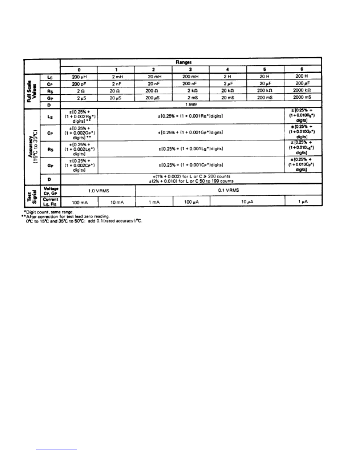
1.2 SPECIFICATIONS
Table 1-1. Model 252 Specific ations
Test Frequency: 1kHz ±1%.
Unknown Excitation: The 1kHz voltage (Vx) and current (Ix) levels listed in Table 1-1 are held
constant by an internal amplitude control circuit.
Measurement Rate: Four per second; one second is required for first reading after connecting
unknown to terminals.
Measurement Dis pla y: 3-1/2 digit LED with decimal point. Blanked for overload con ditions.
Unit Display: Unit of mesurement being displayed by the LED readout is indicated by position
of the range switch, used in conjunction with the desired function button and the
front panel range scale.
External Bias: Rear panel terminals are provided for connection of external supply. 0V to 50VDC,
0.1A maximum. (Read Section 2.2.6 before using external bias.)
Static Charge Protection: Diode and resistor discharge network.
1-2
Page 9

Connection to Unknown: Four-terminal, shielded, connections are provided by the KELVIN KLIPS®
cable assembly (Tegam Part Number 43072) supplied with the Model
252.
Outputs: Analog signals of 1V per 1,000 counts, 1kΩ source resistance is available at rear panel.
L, C, R, or G, with simultaneous output of D for L or C.
Power Consumption: 4 watts typical.
Power Requirements: 100 to 125V or 200to250V, 50/60Hz.
Fuse: 110V: 1/16A 250VAC Slow-Blow
220V:1/20A 250VAC Slow-Blow
Size: Height (with feet) - 100mm (3.9 in.)
Width - 260mm (10.2 in.)
Depth (overall) - 370mm (14.6 in.)
Weight: 3.2kg (7 lb.)
Accessories supplied with Model 252: Part No.
KELVIN KLIPS® Four-Terminal Clips 43072
Instruction Manual 43158
Options Available: Part No.
Model 1412B Universal Limits Comparator 31412B
Sorting Fixture Model 2001 (low frequency) 32001
Cable Assembly (for Model 2001 connection) 43586
Front Panel Dust Cover 43374
Additional Accessories Part No.
Chip Tweezers 2005B/SP5132
Kelvin Klip Rebuild Kit KK100
Chip Tweezer Rebuild Kit 47422
1-3
Page 10

Page 11
SECTION 2
OPERATION
2.1 CONTROLS AND CONNECTORS
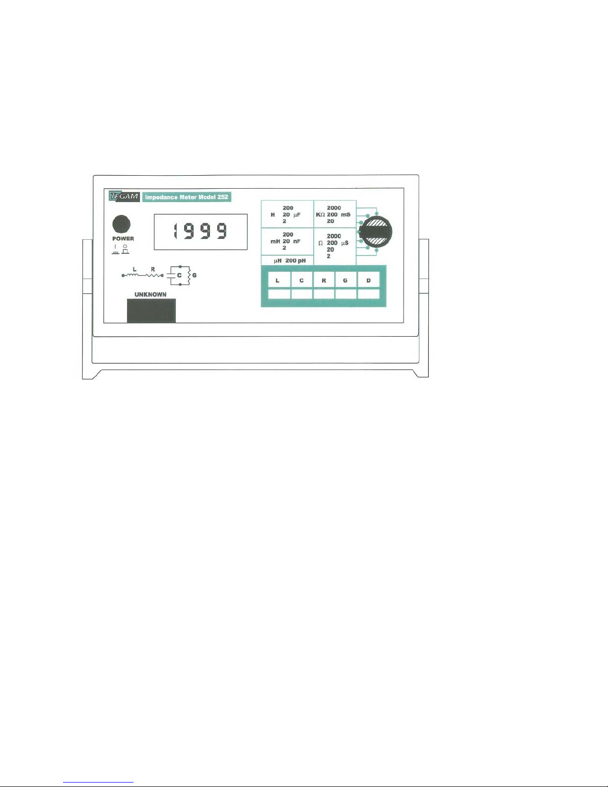
2.1.1 Front Panel
Figure 2-1. Model 252 Front Panel
1. ON/OFF Switch – A push-on, push-off switch for applying and
removing power from the instrument.
2. UNKNOWN Connector – Terminals designed to be used with KELVIN
KLIPS® test leads (Tegam Part No. 43072),
Provided with Model 252, to provide a true
Four-terminal connection to the unknown or
Test fixture.
3. L, R, C, and G Pushbuttons – Function pushbuttons select the type
of meter circuit that will measure
series inductance (L) and resistance
(R) or parallel capacitance (C) and
conductance (G).
2-1
Page 12

4. D Pushbutton -- The push-to-read D (dissipation factor) pushbutton displays the D of a capacitor or
inductor when the C or L function is selected.
5. Range Switch -- Selects the decimal multiplier and units of measurement for the meter circuit being
used. The basic multipliers and units are: H (henrys), mH (millihenrys), µH
(microhenrys), pF (microfarads), nF (nanofarads), pF (picofarads), k Ω (kilohms),
Ω (ohms), mS (millisiemens), and µS (microsiemens).
6. Display — A 3-1/2-digit readout for all functions.
7. Tiltstand Handle -- Aids p orta bility; tilts instrument for easier viewing of the LED display.
2-2
Page 13
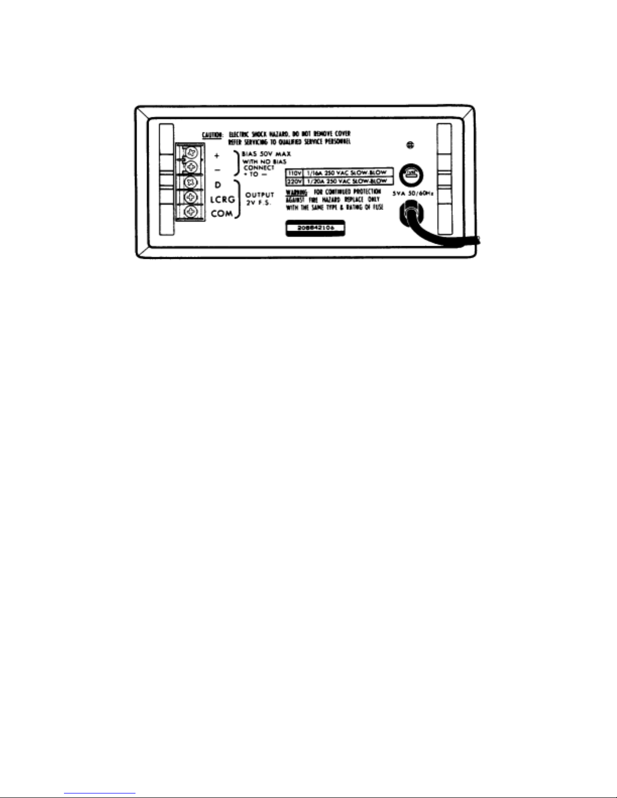
2.1.2 Rear Panel
Figure 2-2. Mod e l 252 Rear Panel
1. Bias Terminals – Allows application of a 2V to 50VDC, 0.1A maximum bias to the
capacitor being measured. (The shorting bar must be in place
when not using bias feature.) See Sectio n 2.3.6 before
using external bias.
2. Output Terminals – Provides two analog signals proporational to the function
selected (L, R, C, or G) and D (for L and C). These terminals
can be used with external DVM’s (for increased full scale
readings or resolution capability), with chart recorders, or with
limits comparators, such as the Tegam Model 1412B.
3. Fuse – A 1/16A, 250V, type MDL Slow Blow for 110V line voltage, or a 1/20A, 250V
type MDL Slow Blow for 220V line voltage.
2-3
Page 14
2.2 OPERATING PROCEDURE
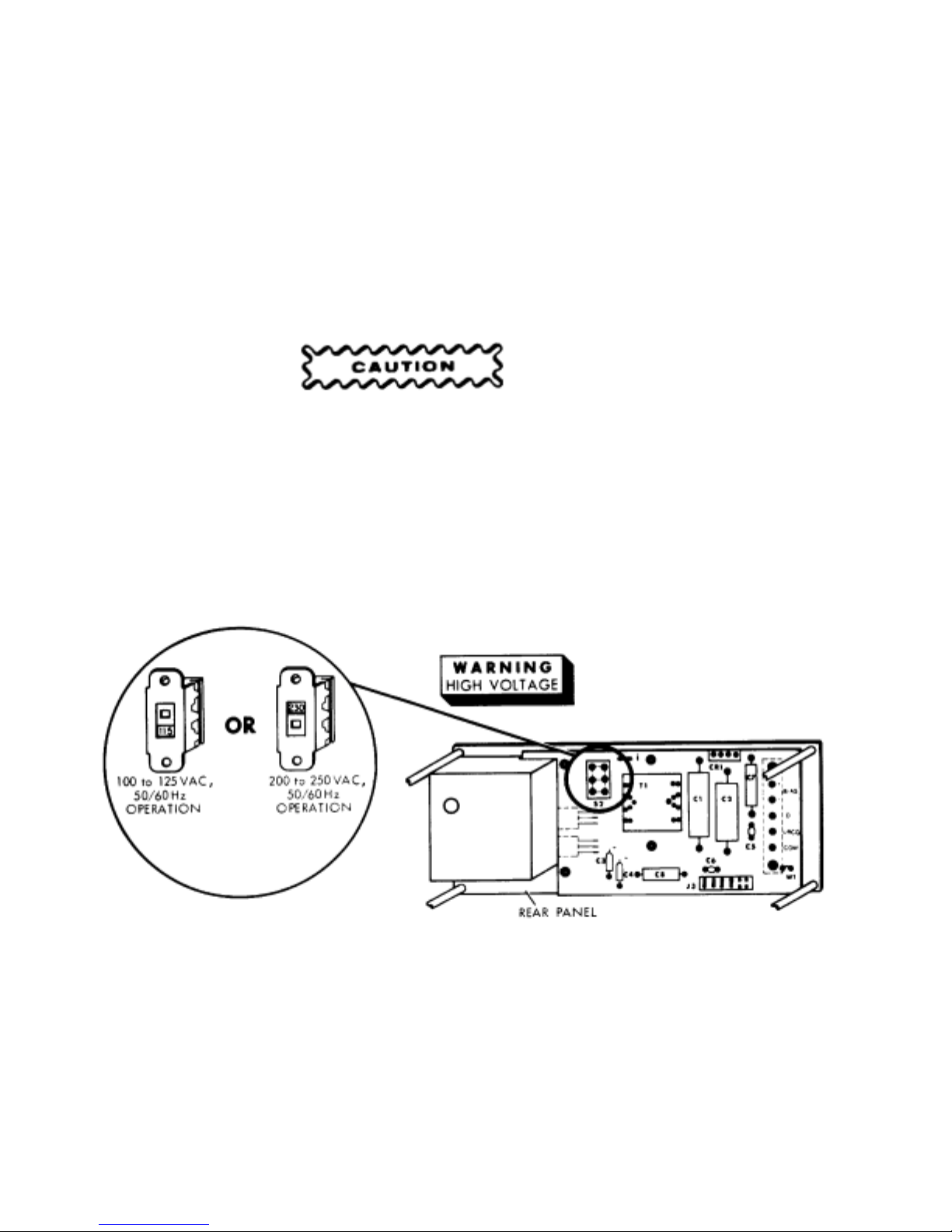
2.2.1 Power Requirements
Before turning the power ON, make sure the instrument is set to the proper line voltage.
The Model 252 contains an internal slide switch to select the nominal line voltage
(see Figure 2-3). In its up position, the switch selects 100 to 125VAC, 50/60Hz operation. In
the down position it sel e c ts 200 to 250VAC, 50/60H z operation.
WHEN CHANGING FROM 110VAC OPERATION TO 220VAC OPERATION (OR
IN OPPOSITE ORDER), BE SURE TO REPLACE THE REAR PANEL AC FUSE
WITH THE PROPER VALUE FOR THE LINE VOLTAGE SELECTED.
Figure 2-3. Line Voltage Switch
2-4
Page 15
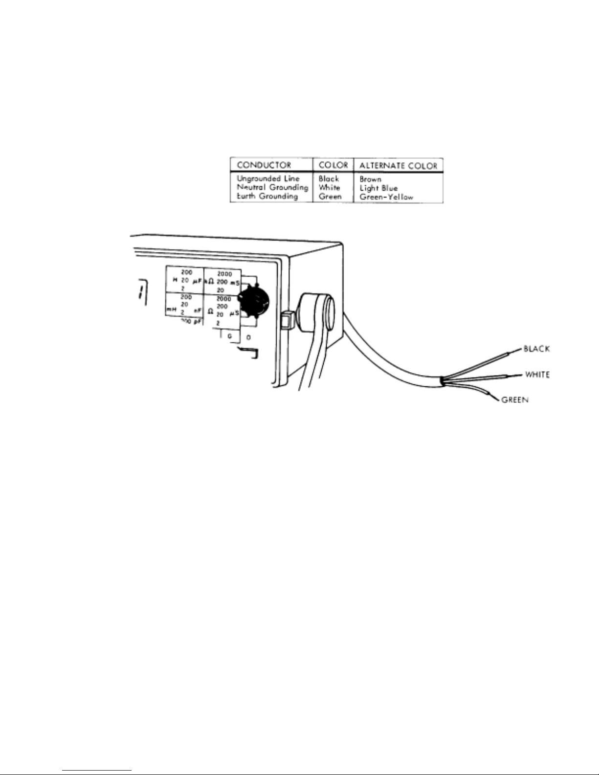
Because of differing power requirements, all instruments shipped outside the United States are without a
power cord connector. When placing a connector on the power cord, care must be taken to assure
the wires are connected properly. The green or green with yellow stripe wire is always connected to
earth ground. The white or light blue wire is connected to the neutral side of the power line. And,
the black or brown wire is connected to the high side of the power line.
2.2.2 Applying Power
The push-on, push-off, ON/OFF button in its depressed position applies power to the measurement
circuitry. When power is applied, the LED display lights and reads zero when in C and G modes or the
display is blank with the decimal point lit in the L and R modes.
2-5
Page 16
2.2.3 Connection to Unknowns
The KELVIN KLIP® test lead set (Tegam Part No. 43072) is plugged into the 252’s front panel
UNKNOWN connector. The test leads connector cover is spring-locking and should be squeezed together
before inserting or removing.
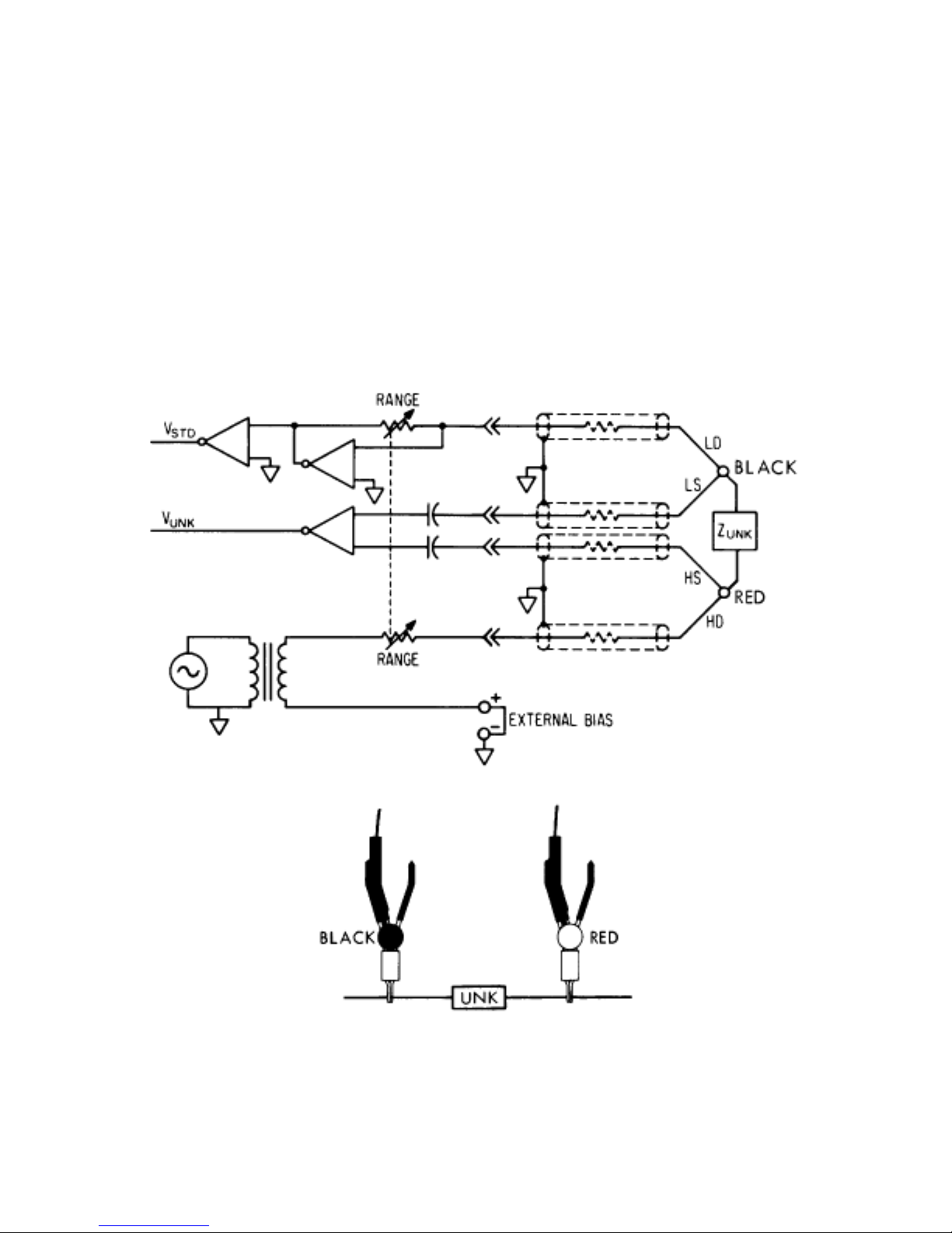
The test leads provide a shielded, four-terminal connection to the unknown (see Figure 2-5a). The clip
with the red hinge-spool provides the HI DRIVE and HI SENSE connectio ns to the unknown and the clip
with the black hinge-spool make the LO DRIVE and LO SENSE connections.
Figure 2-5a.
Figure 2-5a.
2-6
Page 17

Figure 2-5b.
For connection to three terminal unknowns (the third connection is to ground), a ground wire must be
added to the test lead set. This wire is connected as in Figure 2-5b.
2-7
Page 18

2.2.3.1 Test Fixture Compensation
The Model 252 uses a 3.3pF capacitor (C6 in Figure 2-6) to compensate for the capacitance of
the test leads. If the 252 is used with a test fixture, the larger capacitance of the fixture must
also be compensated for. There are two methods for compensating this larger capacitance. The
first method is to make a zero capacitance measurement with the test fixture connected. This
reading is mentally subtracted from all other measurements.
The second method for compensating the larger capacitance is to change the value of C6 from 3.3 pF
to 10 pF and to add an external trim capacitor. The external trim capacitor is connected in parallel with
the unknown and should be of such a value that the test fixture capacitance can be trimmed to zero.
Typically, the maximum value of this trim capacitor is 15pF. The trim capacitor can either be added
to the test cable, between Terminals 1 and 3 of the connector as shown in Figure 2-6, or it can be
added to the test fixture.
Figure 2-6. Test Fixture Compensation
2-8
Page 19

2.2.4 Function Selection
Model 252 is designed to measure series inductance (L), parallel capacitance (C), series resistance (R),
parallel conductance (G), and dissipation factor (D) of inductance and capacitance. One of these
measurement modes is selected by depressing the proper front panel button. (If all buttons are in their
out position, the instrument reverts to the inductance measurement mode.)
Example: Select the capacitance measurement function. (Depress the C pushbutton.)
2-9
Page 20

Example: Select the conductance measurement function. (Depress the G Pushbutton.)
If a negative sign appears on the display when measuring an unknown, possible causes are:
“C” button has been pushed when measuring an inductor.
“L” button has been pushed when measuring a capacitor.
The unknown is more capacitive (or inductive) than suspected. For example, an
inductor that resonates below 1kHz will measure as though it were a capacitor.
A diode requires bias voltage (a negative reading may appear if bias voltage is not applied).
2-10
Page 21

To measure the dissipation factor (D) of a capacitor or inductor, push and hold the D button while the C
or L function is selected. (The display will blank if D is pushed, while the unit is in R or G mode
and the unknown is resistive).
When measuring the conductance (G) of a capacitor or the resistance (R) of an inductor, the R or G
reading may be quite small. In trying to acquire more resolution by moving the range switch to the next
lower range, the display will usually blank, indicating overload. Blanking occurs because the instrument is
still monitoring the reactive component (L or C) in addition to measuring and displaying the loss
component (R or G). In moving to the next lower range, the reactive component becomes too large for
the lower range causing overload and a blanked display.
Example: while measuring a 0.82µF capacitor using the 2µF range, the 252 display reads:
Switching to the conductance (G) mode, the display may read:
2-11
Page 22

Trying further to investigate this reading, you down range from the 20mS range to the 2000µS range.
The display blanks:
The display blanks because, while ranging from 20mS to 2000µS, the capacitance range changed from
2µF to 200nF. Since 0.82µF is too large to measure on the 200nF range, an overload occurs and the
display blanks.
2.2.5 Range Selection
Measurement ranges are selected by a seven-position rotary switch. See Figure 2-7 for full-scale range
values. For maximum display resolution and accuracy, select the range that gives the largest onscale reading. The position of the range switch indicates the readout units (i.e. µH, mH, H, etc.). If either
the reactive or resistive value of the unknown exceeds the range selected, the display will blank.
L
Full Scale
s
C
p
R
s
G
p
Values
D
0
Ω 20 Ω
2
1
Ranges
32
1.999
54
6
200 H20 H2 H200 mH20 mH2 mH200 µH
µF20 µF2 µF200 nF20 nF2 nF200 pF
200
2000 k
2000 m
Ω200 k Ω20 k Ω2 k Ω200 Ω
S200 mS20 mS2 mS200 µS20 µS2 µS
Figure 2-7 Range Chart
2-12
Page 23

Example: Set the instrument to measure 100pF capacitors.
Example: Set the instrument to measure 100kΩ resistors.
If the value of a component is not known, set the instrument to its highest range before connecting the
test leads. Step the instrument down one range at a time until the range with the highest resolution
is reached. If the display is blank after the component is connected, the value of the component is too
large to measure directly, see Section 2.3 for alternate measurement techniques.
2.2.6 Summary of Operation
Press the appropriate function button (L, C, R, or G) and connect the KELVIN KLIPS® to the unknown.
For maximum accuracy, select the range that gives the largest on-scale reading. The measurement is
displayed after one second or less. Repetitive measurements are made at the rate of four per second.
The position of the range switch indicates the readout units (i.e. µH, mH, H, etc.). If the value of the
2-13
Page 24

unknown exceeds the range selected, the display will remain blanked. To measure the dissipation factor
of a capacitor or inductor, push and hold the D button while the C or L function is selected.
2-14
Page 25

Page 26

Equivalent Series Resistance (ESR). To measure series resistance of capacitors, use the Rs function.
Series resistance will be displayed on the front panel.
Series Capacitance. The Ls function can be used to measure series capacitance. (The capacitor is
measured with a constant current rather than a constant voltage.) A negative reading will be shown,
and the following equation must be used to convert the “-Ls” readings to the “Cs” values:
Where: f=frequency in hertz
Cs= series capacitance in farads
Ls=series inductance in henrys (ignore sign)
Dissipation factor (D). The D of large value electrolytic capacitors can be determined using the Ls and Rs
functions using the same range. The following equation converts the Rs and Ls, in counts (ignore the
Sign and decimal point), to D values:
Where: D= dissipation factor
Rs= equivalent series resistance reading in counts
Ls= series inductance in counts
2-16
Page 27

Parallel Capacitance Measurements. The relation between parallel and series capacitance measurements
is:
The following graph illustrates the relation between Cs and Cp. The graph is used to obtain a Cs value
for a capacitor by measuring the Cp and D values of the capacitor. To locate the Cs value, find the
measured D value along the horizontal axis of the graph. (The D reading from the Model 252 will be a
Dissipation Factor value not a Percent Dissipation value.) Move up the graph to the B curve and read
the corresponding value on the righthand vertical axis. Multiply the measured Cp value by this reading to
obtain the desired Cs value.
The A curve on the graph is used with the vertical axis in the same manner as described above. The A
curve and lefthand scale provide the Percent Difference between Cs and Cp.
2-17
Page 28

2.3.3 Inductance Measurements
The 252 measures the total impedance connected to its terminals. Both the unknown inductor and it’s
leads contribute to this impedance. The leads have some resistance and inductance which affect
the value read from the meter.
In making high inductance measurements, avoid AC pickup and keep the stray capacitance to a
minimum. To minimize both effects, keep hands as far as possible from the inductor being measured.
Keep the leads as short and direct as possible. Take care to avoid coupling stray magnetic fields
into the inductor.
For greatest accuracy on low inductance measurements, minimize the lead impedance. Closely
spaced, twisted leads will reduce the inductance and pickup of stray fields. The KELVIN KLIPS®
Cable Assembly will add about 0.5µH to Ls and 0mΩ to Rs. Short the test leads together and
subtract the reading from the unknown inductance measured.
Measuring leakage inductance of transformer windings is an easy task for the Model 252 since
there are no “false nulls” as found in manually-balanced bridges.
2-18
Page 29

Page 30

2.3.5 Determining Dissipation Factor (D) of Capacitors Using Nomograph
Model 252 will measure dissipation factor up to 1.999. For D values greater than 2 the
nomograph should be used. Measure the capacitance of the unknown and record the readout
display in digits only; do not record the decimal point. With the RANGE switch left in the same
position, push the G button and note the readout display in digits only; do not record the decimal
point. Turn to Figure 2-8 for the D-Q nomograph. Use a straightedge to l ine up the Cp digits
recorded (left-hand scale) with the Gp digits recorded (right-hand scale). D is taken from the
right-hand side of the center scale where the straightedge crosses. For example, with a Cp digital
display of “200” and a Gp digital displ ay of “300”, D is 2.3. Accuracy of D is primarily limited by
interpolation of the nomograph.
Dissipation factor may be determined more accurately by the formula:
Where: D = dissipation factor
Gp = parallel conductance reading in counts
Cp = parallel capacitance in counts
See Table 1-1 for accuracy of Cp and Gp measurements.
Electrolytic capacitors with high dissipation are usually unstable and the measured values may drift.
2-20
Page 31

Figure 2-8. Model 252 D-Q Nomograph
2-21
Page 32

2.3.6 Using the Bias Feature
TO AVOID PERSONAL INJURY FROM ELECTRICAL SHOCK OBSERVE SAFETY
PROCEDURES AS NEEDED FOR THE BIAS VOLTAGE APPLIED.
Bias voltage is necessary or desirable when measuring the capacitance of diodes or of some
electrolytic or tantalum capacitors.
There is a provision on the rear panel for connecting an external bias source of zero
to 50VDC. Remove the shorting link between BIAS terminals when using this feature.
If the external bias supply is not a low AC impedance type, it should have a capacitor
bypass of five times the range full-scale value connected across the bias terminals. The
bias supply should be current limited to 0.1A maximum.
With no bias supply connected, the rear-panel + and – terminals must be strapped
together.
Figure 2-9. Rear Panel
2-22
Page 33

Page 34

3. Locate the Power Supply Circuit Assembly, Part No. 53157. (Attached to the rear panel.)
4. Remove jumper wire W1 from this assembly (see Figure 2-10).
Figure 2-10. Power Supply Circuit Assembly
5. Locate the Range Switch on the front panel.
6. Unsolder and isolate the ground solder lug from the Range Switch terminal and black
wire, making sure that the black wire remains attached to the Range Switch terminal (see
Figure 2-11).
Figure 2-11
7. Replace instrument cover.
2-24
Page 35

The modification of instruments with Serial Numbers 929000 and greater is as follows:
1. Locate the connector strip on the rear panel (see Figure 2-12).
2. Remove and isolate the spade lug from the terminal marked COM.
Figure 2-12
To make measurements of grounded unknowns, connect the grounded side of the unknown
to the KELVIN KLIPS® with the red insulating hinge-spool and the ungrounded end to the clip
with the black spool (see Figure 2-13).
Figure 2-13
2-25
Page 36

Page 37

5. Move the range switch to the range with the highest resolution displayed (see Section 2.2.5) unless
that range uses excessive test current for the size of battery being measured. See Table 1-1 for range
test currents.
Figure 2-14. Measuring Battery Impedance
2-27
Page 38

The Ls function must be used to measure the series capacitance of a battery. Instrument set up is the
same as for Rs measurements (Figure 2-14). A negative reading will be shown, and the following
equation must be used to convert the “-Ls” reading to “+Cs” values:
Where: f = frequency in hertz
Cs = series capacitance in farads
Ls = series inductance in henrys
Care must be taken so the measurement current level of the 252’s internal source does not exceed
the rating of the battery being tested. See Table 1-1 for range test currents.
2.3.10 Component Sorting
Model 252, when used with Tegam, Inc. Model 1412B Limits Comparator, sorts components according
to percent deviation and dissipation factor, simultaneously. Component sorting can be manual or
automatic; Model 1412B provides four contact closures for operating automatic component
handling equipment.
2-28
Page 39

Model 1412B front panel controls set upper and lower limits around a nominal value (L, R, C, or G),
with either of two full scale ranges - - 10% or 100%. An upper limit for dissipation factor (D) is also
set by a front panel control. Test results are shown by four front panel LEDs. They indicate:
GO indicates value between – and + % limits and less than D limit.
LO indicates value less than - % limit.
HI indicates value greater than +% limit.
D HI indicates dissipation factor greater than limit.
Connect the 252 and 1412B as shown in Figure 2-15.
Tegam Part No. 42855
Figure 2-15 Model 252 and Model 1412B Interconnection
2-29
Page 40

Operation
The following instructions assume Model 252 and Model 1412B are connected and both are
turned on.
Model 252 setup: (for capacitor sorting)
1. Push the C button on the Model 252 front panel.
2. Set the range switch to give maximum resolution on the display.
Model 1412B setup:
1. Set the rear panel V REF switch to INTERNAL.
2. Set NOMINAL VALUE switches to anticipated value.
3. Set LIMITS FULL SCALE toggle switches, and % LIMITS and D
LIMIT dials to desired limits.
The measurement:
Connect unknown to the Model 252. If the unknown is within the set limits, the GO LED
will light. If it is not within limits, the appropriate indicator will light.
2-30
Page 41

Example: Sort 15 µF capacitors within +25%, -15% limits with a maximum dissipation limit of
0.0250. Instrument set up is as follows:
Model 252:
Function and Range settings
2-31
Page 42

Page 43

SECTION 3
CIRCUIT DESCRIPTIONS
3.1 GENERAL DESCRIPTION
When measuring Cp or Gp, a voltage is applied across the unknown and range resistor in
Figure 3-1. The voltage across the unknown is held constant to within one part in several
thousand by the 1kHz oscillator feedback control circuit. A current proportional to the value
of the unknown impedance is produced through the range resistor. The resultant voltage drop
across the range resistor is separated into two vector components by the Phase Sensitive
Detectors (PSD) and Reference Voltage Generator (RVG). Receiving gating signals from RVG, the
PSD will measure Gp, the component in phase (0°) with RVG, and Cp, the component at
quadrature (90°). The selected detector output is then fed to the A/D Converter which has a
readout of 1000 counts/volt.
When measuring Ls or Rs, a voltage is applied across the unknown and range resistor in Figure 3-1.
the voltage across the range resistor is held constant to within one part in several thousand by
the 1kHz oscil lator feedback control circuit. With a constant current flowing through the
unknown, a voltage proportional to the value of the unknown impedance is developed across the
unknown. The resultant voltage drop is separated into two vector components by the Phase Sensitive
Detector (PSD) and Reference Voltage Generator (RVG). Receiving gating signals from the RVG, the PSD
will measure Rs, the component in phase (0°) with the RVG, and Ls, the component at quadrature (90°).
The selected detector output is then fed to the A/D Converter which has a readout of 1000 counts/volt.
3-1
Page 44

Figure 3-1. Model 252 Simplified Diagram
When measuring the dissipation factor (D) of inductors or capacitors, an analog ratio
circuit is used. This circuit compares the loss component (Rs or Gp) to the reactive
component (Ls or Cp) and presents a voltage proportional to D to the A/D Converter.
Analog output voltages are available at the rear of Model 252 for the selected function
(L, C, R or G) and simultaneous D (for L or C unknowns).
3-2
Page 45

Page 46

4.1.1 Power Supply Check
Setup – turn on instrument and allow ten minute warm-up period; then remove cover. Check –
Power supply voltages at C44 and C45 should be + and -5V +/-5% (4.75V to 5.25V). Use
rear panel COM terminal for voltmeter low input.
4.1.2 Oscillator Adjust
Setup – Press R function button. Set RANGE switch to 2000 ohms and short test leads
together. Connect voltmeter high input to Test Socket (J5) pin (2) and frequency counter
input to J5 pin (1). Use rear panel COM terminal for circuit common. Adjustment
– Set trimmer
S for DVM reading of 0V (+/-0.2V). Counter reading should be 1000Hz (+/-10Hz).
4.1.3 L,C,R,G Alignment
1. R, G PHASE DETECTOR ZERO TRIM. Setup – Press R function button and set RANGE
switch to 2000 ohms and short test leads together. Connect DVM input to J5 pin (6).
Adjustment
– Set trimmer P for +0.3mV ±0.1mV on DVM.
2. UNKNOWN AMP COMMON MODE TRIM. Setup – Press R function button and set
RANGE switch to 2 ohms and short test leads together. Adjustment - Adjust trimmer J for
DVM reading of 0V +/-0.3mV at J5 pin (6).
3. L, C PHASE DETECTOR ZERO TRIM. Setup – Press L function button and set RANGE
switch to 200mH. Short test leads together and connect DVM input to J5 pin (5).
Adjustment – Set trimmer M for +0.3mV +/-0.1V on DVM.
4. L, C, R, G OUTPUT AMP ZERO TRIM. Setup – Same as step 3 except connect DVM
input J5 pin (4). Adjustment – Set trimmer V for 0V +/-0.3mV on DVM.
5. UNKNOWN AND RANGE AMP PHASE TRIM. Setup – Press C function button and set
RANGE switch to 200nF. Connect decade capacitor to unknown test leads and set at
160nF (±5%). Adjustment – Note voltage at J5 pin (6) and then push L function button,
again noting J5 pin (6) voltage. The two should be equal (±0.3mV). If not, adjust
trimmer X until they are. Next adjust trimmer D for 0V ±0.3mV output at J5 pin (6) for
both L and C functions.
6. QUADRATURE GATE PHASE TRIM. Setup
– Press R function button and set RANGE
switch to 2000Ω. Connect 1000Ω (±0.05%) standard to unknown test leads. Adjustment –
Set trimmer L for DVM reading of 0V ±0.3mV at J5 pin (5).
7. R, G FULL SCALE TRIM. Setup
– Same as step 6. Adjustment – Set trimmer K for front
panel digital reading of 1000. With DVM, read voltage at J5 pin (4) and adjust trimmer R for
+1.0V (±0.5mV).
8. L, C FULL SCALE TRIM. Setup
Connect 100nF (±0.05%) standard to the unknown test leads. Adjustment
– Press C function button and set RANGE switch to 200nF.
– Set trimmer N
for front panel reading of 1000.
4-2
Page 47

4.1.4 Dissipation Factor (D) Alignment
1. LOW LEVEL ZERO TRIM. Setup – Press C function button and set RANGE switch to 200nF.
Connect a low loss (D<0.0002) decade capacitor to unknown test leads. Adjustment – Set the decade
capacitor to 105nF and, with a DVM, note the voltage at J5 pin (3) or D output terminal at the rear
panel. Set the decade to 5nF and again note the voltage. If the two voltages are not equal (+/-1mV),
adjust trimmer W until switching between 105nF and 5nF procedures equal readings.
2. HIGH LEVEL ZERO TRIM. Setup – Same as step 1. Adjustment – Set decade capacitor to 100nF
and adjust trimmer U until voltage at J5 pin (3) or D output is 0V ±0.3mV.
3. D FULL SCALE TRIM. Setup – Same as step 1. Adjustment – Set the decade capacitor for a
front panel C reading of 159.2nF. Connect the 1000 ohm standard resistor in parallel with
the decade capacitor. Set trimmer T for a front panel D reading (push D button) of 1.000.
4. 200pF RANGE D TRIM. Setup – Press C function button and set RANGE switch to 200 pF.
Connect the low loss (D<0.0002) decade capacitor to unknown test leads. Adjustment - Set
the decade to 100pF (+/-20%) and adjust trimmer H for 0V +/- 0.3V at J5 pin (3), or D output.
5. 2nF RANGE D TRIM. Setup – Same as step 4, except set RANGE switch to 2nF. Adjustment –
Set decade to 1nF (+/-20%) and adjust trimmer F for 0V +/-0.3mV at J5 pin (3), or D output.
6. 20nF RANGE D TRIM. Setup – Same as step 4, except set RANGE switch to 20nF. Adjustment –
Set decade to 10nF (+/-20%) and adjust trimmer E for 0V +/-0.3mV at J5 pin (3), or D output.
7. 2µF RANGE TRIM. Setup – Same as step 4, except set RANGE switch to 2µF. Adjustment –
Set decade to 1µF (+/-20%) and adjust trimmer C for 0V +/-0.3mV at J5 pin (3), or D output.
8. 20µF RANGE D TRIM. Setup – Set RANGE switch to 20µF and connect a 10µF (+/-20%)
capacitor (D known to +/-0.001) to unknown test leads.
Adjustment – Adjust trimmer B for front panel D reading (push D button) equal to D value
of the 10µF capacitor.
9. 200µΗ RANGE D TRIM. Setup
– Press the L function switch and set the RANGE switch to
200µH. Short the Kelvin Klips together and note the zero inductance (approximately +5 counts)
for the use in the adjustment. Connect a 1.2 ohm, 5% carbon composition resistor to the test
leads.
Adjustment
– Adjust trimmer A for a display equal to, or -1 count from the zero inductance
value noted when the Kelvin Klips were shorted together.
4-3
Page 48

Figure 4-1
4-4
Page 49

4.2 MAINTENANCE
This section of the manual contains maintenance information for use in preventative maintenance,
corrective maintenance,and troubleshooting of the Model 252.
4.2.1 Preventative Maintenance
REMOVAL OF INSTRUMENT COVERS MAY CONSTITUTE AN ELECTRICAL HAZARD
AND SHOULD BE ACCOMPLISHED BY QUALIFIED SERVICE PERSONNEL ONLY.
Preventive maintenance performed on a regular basis will improve the reliability of this instrument.
It may include cleaning, visual inspection, or even monitoring the operating environment.
4.2.1.1 Cleaning
AVOID THE USE OF CHEMICAL CLEANING AGENTS WHICH MIGHT DAMAGE THE
PLASTICS USED IN THIS UNIT. DO NOT APPLY ANY SOLVENT CONTAINING
KETONES, ESTERS OR HALOGENATED HYDROCARBONS. TO CLEAN, USE ONLY
WATER SOLUBLE DETERGE NTS, ETHYL, METHYL, OR ISOPROPYL ALCOHOL.
Exterior. Loose dust may be removed with a soft cloth or a dry brush. Water and mild detergent
may be used; however, abrasive cleaners should not be used.
Interior. Use low-velocity compressed air to blow off the accumulated dust. Hardened dirt can be
removed with a cotton-tipped swab, soft, dry cloth, or a cloth dampened with a mild detergent
and water.
4-5
Page 50

4.3 Preparation for Calibration or Repair Service:
No user serviceable parts are available for this equipment. If a problem arises and you have
verified that the cause for malfunction cannot be solved in the field then the instrument should
be sent to TEGA M for service. Before sending a unit in for service, an RMA, (Returned Material
Authorization), number must be assigned to your instrument. You can contact TEGAM customer
service via the TEGAM website, www.tegam.com or calling 440.466.6100 or 800.666.1010.
The RMA number is unique to your instrument and will help us identify you instrument and to
address the particular service request by you which is assigned to that RMA number.
Of even importance, a detailed written description of the problem should be attached to the
instrument. Many times repair turnaround is unnecessarily delayed due to a lack of repair
instructions or of a detailed description of the problem.
This description should include information such as measurement range, and other instrument
settings, type of components being tested, are the symptoms intermittent?, conditions that may
cause the symptoms, has anything changed since the last time the instrument was used?, etc. Any
detailed information provided to our technicians will assist them in identifying and correcting the
problem in the quickest possible manner. Use a copy of the Repair and Calibration Service form
provided on the next page.
Once this information is prepared and sent with the instrument to our service department, we will
do our part in making sure that you receive the best possible customer service and turnaround
time possible.
4-6
Page 51

Expedite Repair & Calibration Form
Use this form to provide additional repair information and service instructions. The Completion of this form
and including it with your instrument will expedite the processing and repair process.
RMA#:
Serial
Number:
Technical Contact: Phone Number:
Additional
Contact Info:
Company:
Instrument Model #:
Repair Instructions:
Evaluation Calibration Only Repair Only Repair & Calibration Z540 (Extra Charge)
Detailed Symptoms:
Include information such as measurement range, instrument settings, type of components being tested, is
the problem intermittent? When is the problem most frequent?, Has anything changed with the application
since the last time the instrument was used?, etc.
Page 52

Page 53

THE GLOBAL SOURCE FOR PROVEN TEST & MEASUREMENT TECHNOLOGY
TEN TEGAM WAY, GENEVA, OHIO 44041
PHONE 440-466-6100 FAX 440-466-6110
WARRANTY OF TRACEABILITY
The reference standards of measurement of Tega m, Inc., are compared with the
U.S. National Standards through frequent tests by the U.S. National Institute of
Standards and Technology. The Tegam working standards and testing apparatus
used are calibrated against the reference s tandards in a rigorously maintained
program of measurement control.
The manufacture and final calibration of all Tegam instruments are controlled
by use of the Tegam reference and working standards and testing apparatus in
accordance with established procedures and documented results. (Reference
ANSI/NCSL Z540-1-1994)
Final calibration of this instrument was performed with reference to the mean
values of the Tegam reference standards or to ratio dev ices that were verified
at the time and place of use.
DISCLAIMER of IMPLIED WARRANTIES
The foregoing warranty of Tegam is in lieu of all other warranties, expressed or
implied. Tegam specifically disclaims any implied warranties of merchantability or
fitness for a particular purpose. In no event will Tegam be liable for special or
consequential damages. Purchaser’s sole and exclusive remedy in the event any item
fails to comply with the foregoing express warranty of Tegam shall be to return
the item to Tegam, shipping charges prepaid, and at the option of Tegam obtain
a replacement item or a refund of the purchase price.
Ten Tegam Way, Geneva, Ohio 44041 Phone: 440-466-6100 Fax: 440-466-6110
 Loading...