

Page 1

MODEL 2411B
2MS/s Arbitrary Waveform Generator
Operation Manual 810029-CD
Rev. D
Publication Date: November 2005
Page 2

The Tegam 2411B is a high resolution 2 MS/s Arbitrary Waveform Generator with
optional Windows® based waveform creation capability. The updated front panel
and the optional WaveWork
TM
Pro +. waveform creation software make the 2411B the
easiest way to create and output the waveforms you need. The additional channels
needed for multi-phase applications can be met with a simple connection between
two or more 2411Bs. It’s combination of bench-top and system features, GPIB (optional) and RS232 (standard) interfaces and the integrated software which is optional and
runs under Windows make this waveform generator package a versatile tool useful to
create your waveforms for mechanical simulation, engine simulation, medical electronics, modulated sine wave applications and many more applications.
Lab-quality performance
z20 commonly used waveforms front-panel selectable
zContinuous or triggered output--5 standard modes
z16-bit high-fidelity waveforms--0.005% THD (typical) at 2kHz
zHigh resolution output up to 2 MS/s
zVery large waveform memory--64k words
zLoop and link up to 100 waveforms (Sequence option)
Convenient bench-top features
zUpdated front panel includes control knob and back-lighted LCD
zCursor Control of amplitude, offset, sample clock and frequency.
zPortable, small profile package
System features
zRS-232 included
zWaveform creation software under Windows available
z4 programmable Sync pulses per waveform
TEGAM 2411B
2 MS/s Arbitrary Waveform Generator
Page 3
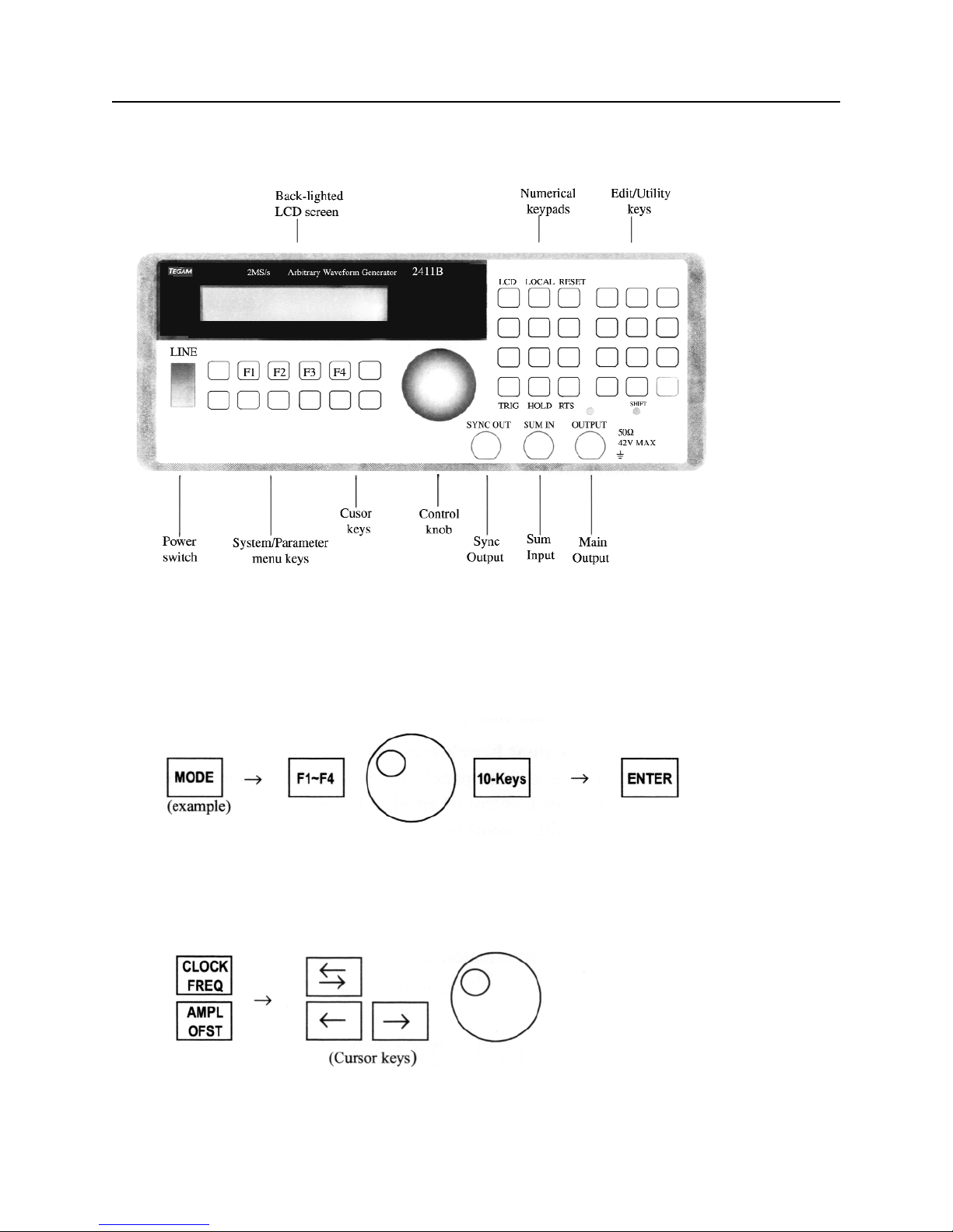
The Front Panel
Front-Panel Entry
Press one of the System/Parameter menu keys or the Utility/Edit menu keys, and use soft keys
(F1~F4), knob or 10-keys to make selection. Then, press ENTER key.
Use the CLOCK/FREQ or AMPL/OFST key and the knob to make parameter changes. Use double
arrow key to switch parameter selection.Use arrow keys to select digits and ranges.
II
Page 4
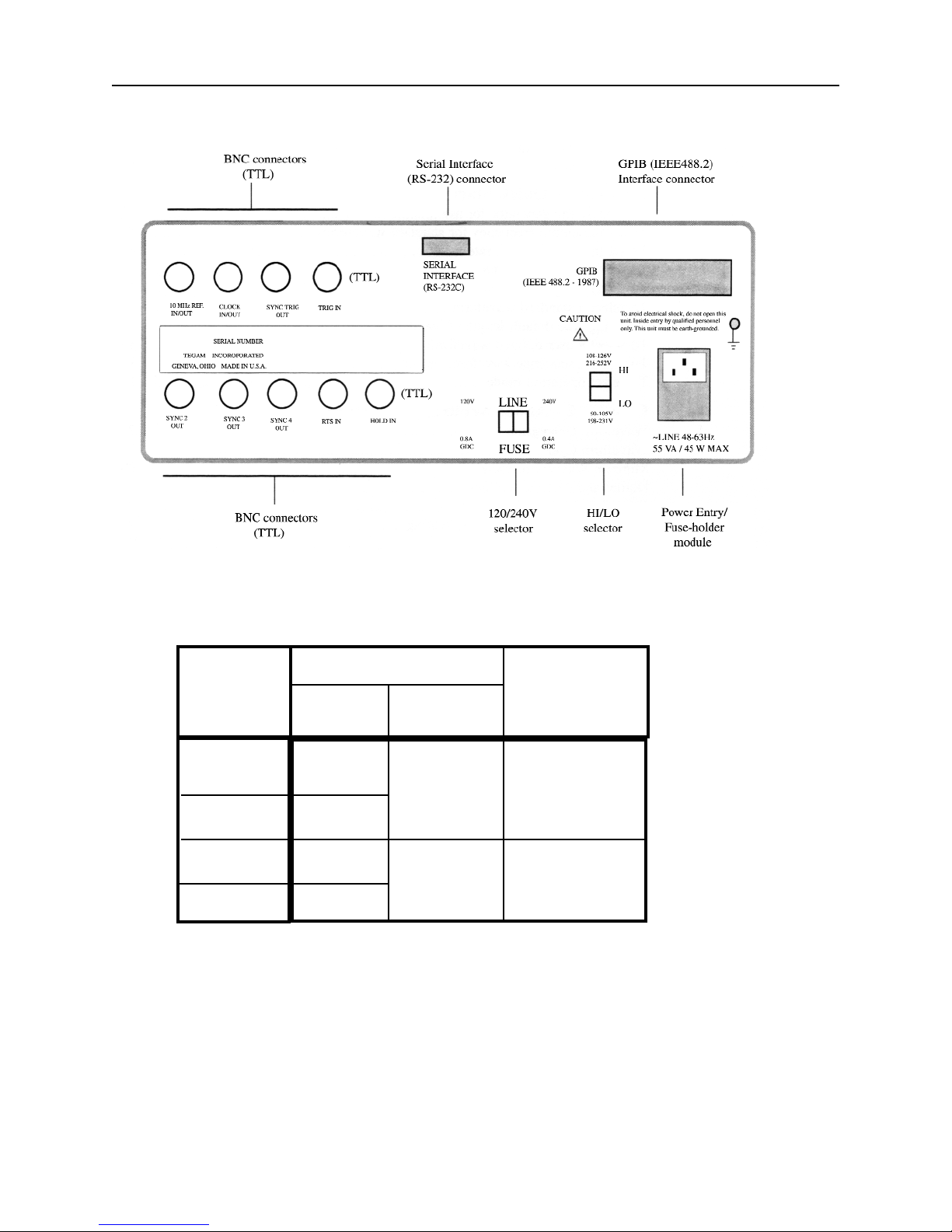
The Rear Panel
III
Mains
Voltage
Range (V)
Power Mains Setting
Hi / Lo Range Fuse Rating
Selector Selector
90 ~ 105
108 ~ 126
198 ~ 231
216 ~ 252
Lo
120V 0.8A GDC
Hi
Lo
240V 0.4A GDC
Hi
Page 5

Table of Contents
The Front Panel...........................................................................................................................II
Front Panel Entry.........................................................................................................................II
The Rear Panel / Power Mains Setting......................................................................................III
Technical Specification.............................................................................................................VII
In This Manual........................................................................................................................VIII
Chapter 1 - Quick Start
To prepare the generator for use.............................................................................................1 - 2
To set the output frequency for standard waveforms.............................................................1 - 3
To set the sample clock rate....................................................................................................1 - 4
To set the output amplitude.....................................................................................................1 - 5
To set the output offset voltage...............................................................................................1 - 6
To select a standard waveform...............................................................................................1 - 7
To change the default length of standard waveform..............................................................1 - 8
To select a user-defined waveform.........................................................................................1 - 9
To select a sequence waveform (option)...............................................................................1 -10
To select operating mode.......................................................................................................1-12
Chapter 2 - About Arbitrary Waveforms
Waveform Generation.............................................................................................................2 - 2
Waveform Cycle..................................................................................................................... 2 -2
More on Waveform Cycle...................................................................................................... 2 -3
Digital and Analog Scaling.....................................................................................................2- 3
Other Considerations...............................................................................................................2- 3
Examples-Digital and Analog Scaling....................................................................................2 - 4
Waveform Types.....................................................................................................................2- 5
Sync Pulse...............................................................................................................................2- 6
Sync Outputs...........................................................................................................................2- 7
2411B Block Diagram.............................................................................................................2- 8
Chapter 3 - Front-Panel Menu Operation
Parameter Control
MODE menu............................................................................................................ 3 - 2
Sample Clock and Frequency (SCLK/FREQ) menu...............................................3 - 2
Amplitude/Offset (AMPL/OFST) menu..................................................................3 - 2
Function (FUNC) menu............................................................................................3 - 3
OUTPUT menu........................................................................................................3 - 4
Waveform Setup.....................................................................................................................3 - 4
Waveform Edit.................................................................................................................... ...3 - 4
System Control........................................................................................................................3 - 5
Default Settings.......................................................................................................................3 - 6
Standard Waveform List......................................................................................................... 3- 9
Chapter 4 - Waveform Creation System
Components............................................................................................................................4 - 2
User Interface.........................................................................................................................4 - 2
Memory Organization
Introduction..............................................................................................................4 - 4
Default Partitioning.................................................................................................4 - 4
Waveform Numbering..............................................................................................4 -4
Changing Waveform Block Length.........................................................................4 - 4
Waveform Number Block Length............................................................................4 - 5
Deleting Waveform..................................................................................................4 - 5
Inserting New Waveform numbers..........................................................................4 - 5
IV
Page 6

Table of Contents
Waveform Creation Using Front Panel
Introduction...............................................................................................................4 - 6
Line Mode................................................................................................................4 - 6
Vertex Mode............................................................................................................ 4 - 9
Math Operation........................................................................................................4-13
Examples.................................................................................................................4-14
Sequence Generator (Option)
Introduction...............................................................................................................4-17
Programming a Sequence.........................................................................................4-17
Deleting a Sequence.................................................................................................4 -18
Adding a Step into an Existing Sequence................................................................4-18
Deleting a Step from an Existing Sequence.............................................................4-19
Modyfying a Step within an Existing Sequence......................................................4-19
WaveWorks Pro Software (Option)........................................................................................4- 20
Chapter 5 - Multi-Instrument Operation
Basic Connection.....................................................................................................................5- 2
Multiple Phase Connection......................................................................................................5- 3
Multiple Phase Operation........................................................................................................5-4
Multiple Phase Setup...............................................................................................................5-6
Chapter 6 - Performance Verification
Introduction..............................................................................................................................6-2
Test Equipment Required.........................................................................................................6-2
Verification Test.......................................................................................................................6-2
Verification Test Sheet.............................................................................................................6-4
Chapter 7 - Remote Interface Operation
Introduction..............................................................................................................................7-2
To set the GPIB address..........................................................................................................7- 2
To set the RS-232 parameters..................................................................................................7- 3
RS-232 Adapter Cables...........................................................................................................7- 4
Before sending commands......................................................................................................7-5
Command Features
Command Execution.................................................................................................7- 5
Waveform Selection..................................................................................................7- 6
Waveform Deletion...................................................................................................7 - 6
Command Set..........................................................................................................................7- 7
Reset and Default Values...................................................................................................... 7-14
RS-232 Programming Example.............................................................................................7 -16
GPIB Programming Example................................................................................................7-18
Chapter 8 - Advanced Remote Operation
RS-232 Overview
Introduction...............................................................................................................8- 2
Interface Requirements.............................................................................................8 - 2
Verifcation of Communication..................................................................................8- 3
Command Syntax......................................................................................................8- 3
Common Commands.................................................................................................8- 3
Event Register and Status and Error Reporting........................................................8-4
Functional Syntax Elements......................................................................................8-4
V
Page 7

Table of Contents
GPIB (optional) (IEEE-488.2) Overview
Introduction................................................................................................................8-7
Common Commands.................................................................................................8-8
Status and Event Registers........................................................................................ 8-9
Functional Elements - Syntax and Nomenclature...................................................8 - 11
Error Reporting........................................................................................................8-12
Data Formats
Decimal Numeric Program Data..............................................................................8 -13
Arbitrary Block Program Data.................................................................................8 -14
Remote Command Set
Introduction..............................................................................................................8 -15
Command Sequence..................................................................................................8-15
Command Execution................................................................................................8 -15
Command Set Hierarchy...........................................................................................8-16
Stacked Queries........................................................................................................8-16
Command Set............................................................................................................8 -17
Waveform Editing Principles..................................................................................................8-19
Waveform Memory Format
Decimal Waveform Download.................................................................................8- 21
Binary Waveform Download....................................................................................8-22
Example....................................................................................................................8-23
Binary Download Test Program for GPIB...............................................................8-25
Arbitrary Sync Pattern Programming
Overview.................................................................................................................. 8-28
Start/Length Sync Programming..............................................................................8-28
Block Sync Programming.........................................................................................8 -29
Combined Waveform and Sync Programming.........................................................8-30
Single Point Sync Query...........................................................................................8-31
Multiple Point Sync Query.......................................................................................8- 31
Sequence Generator Operation (Option)
Add Sequence...........................................................................................................8-33
Auto Sequence..........................................................................................................8-33
Sequence...................................................................................................................8-33
Sequence Burst.........................................................................................................8-34
Sequence Burst Number...........................................................................................8-34
Appendix
Menu Logic Tree
Standard Waveshape Equations
Amplitude/Offset Graph
Index
Warranty
VI
Page 8

Techical Data Sheet
TEGAM 2411B 2MS/s Arbitrary Waveform Generator
VII
Output Waveforms
Up to 100 High-Definition User-defined Waveforms,
Standard Waveforms: Sine, Square, Triangle, ±Sawtooth,
DC, ±Pulse, ±Exponential, AM, SCM, FM, Lin/Log
Sweep, Sin x/x (Sine), Gaussian, Haversine, Circle,
Noise.
4 programmable sync pulses per waveform.
Sequence Generator (Optional)
Waveform: Transient-free Loop and Link
Repetitions: Loop: 1,048,575 times Link: 100 waveforms
Program: 1000 Steps total
File: 100 Sequences
Waveform
Storage: 100 waveforms
Resolution:
Horizontal Points: 65,504 max., 16 min.
Vertical Points: 16 bits, 65,536 (-32768 to +32767)
Sample Rate:
Range: 0.1 Hz to 2MHz (10s to 500ns)
Resolution: 4 digits
Accuracy:±50ppm
Transition Time: <150ns
(Tested with square wave, filter off, 10Vp-p, 50Ω
termination.)
THD + Noise: -86dB typical (2kHz sinewave)
(Tested with 80kHz measurement bandwidth, 2 MHz
clock, sinewave, 1000 points, filter on. full amplitude, 50Ω
termination.)
Amplitude and Offset
Range
Resolution Accuracy
±1.00 to 10V 10mV 1 % of setting + 20mV
±100mV to 999mV 1mV 3% of setting + 5mV
±10mV to 99.9mV 100mV 5% of setting + 1mV
(Tested with 1kHz sinewave plus DC offset, 50
Ω
source
impedance, open circuit.)
Selectable Analog Filter
Cutoff: 700kHz, 7th order; 40kHz, 3rd order
Operational Modes
Continuous: Output runs continuously between selected
memory address locations
.
Triggered: Output at start point until triggered, then runs
once.
Gated: As triggered except output is continuous until gate
signal ends.
Burst: Each trigger outputs a preprogrammed number of
waveforms from 1 to 1,048,575.
Toggled: Alternate triggers gate the output waveform.
Master-Slave: For multi-unit operation.
Cont-Sync: multiple units run continuously in sync with
the master unit
Trig-Sync: multiple units run in sync with the master unit
for one cycle when the master unit is triggered.
Trig-Sequence: a tail-chasing mode between the master
and the slave unit initiated by triggering the master unit.
Outputs
Output: Front-panel main waveform output, 50Ω
impedance.
Sync Outputs: Front-panel TTLsync output, 50Ω
impedance plus 3 rear-panel TTL outputs.
Programmable.
Clock Out: Rear-panel AWG waveform sample clock
output (TTL). x2 sample clock.
Reference Out: Rear-panel internal 10MHz reference
output (TTL).
Sync Trigger Out: Triggers additional units
Inputs
Trigger Input: Rear-panel TTL trigger input for trig-
gered,gated, burst, toggled and master-slave modes.
External TTL Sample Clock Input:< 4MHz
Reference In: Rear-panel 10MHz reference input will
phase lock the internal crystal-controlled oscillator.
Trigger Sources
External Trigger Input
Manual Trigger
Waveform Creation Tools (Option)
Software:
WaveWorks Pro+ for Windows
Operating System: Windows 2000, 98 or 95.
PC Requirements: 486DX or better with 4MB RAM
space
Interface: COM port or National Instrument AT-GPIB
card (or equivalent)
Standard Function: 30
Math Operation:
Operators: 13
Transfer Functions: 20
Sequence Creation (optional hardware required)
Waveform Analysis:
Frequency Domain: FFT and IFFT: up to 500th
harmonic, graphic display and
tabulation
Time Domain: Waveform and Digital Pattern
Edit: Point, Vertex and Harmonics (FFT, IFFT).
Computer Interface
RS-232C: 19.2kBaud. max.
GPIB (optional): IEEE Std. 488.2-1987
General
Stored Settings: 31
Temperature Range: +23 °C ± 3°C for specified oper-
ation. Operates 0°C to +50°C. Storage -20°C to +60°C.
Dimensions: 11.5cm (4.53 in.) H; 25.8cm (10.14 in.)
W; 30cm (11.81 in.)D.
Weight: 5.0kg (11 Ibs)
Power: 55VA; 45W (max) 100/120/220/240 VAC. +5%,
-10%; 48 to 63 Hz.
Weight and dimensions are approximate. Errors and omissions excepted. Prices and specifications subject to change without notice. TEGAM
is the registered trademark of TEGAM, Inc.
© Copyright 2000 TEGAM Inc. All rights reserved.
Page 9

Quick Start:
Chapter 1 will prepare you to use the basic parameters of the arbitrary waveform generator
within a short time.
About Arbitrary Waveforms: Chapter 2 provides you the basic concept of arbitrary waveform genera-
tion.
Front-Panel Menu Operation: Chapter 3 describes the front-panel menu operation.
Waveform Creation System: Chapter 4 describes the overview of waveform creation system.
Multi-Instrument Operation: Chapter 5 describes the basic connection and the multiple unit operation
for multiphase applications. You will leam about the hardware connections and the available masterslave mode.
Performance Verification: Chapter 6 describes the procedure to verify the2411B specification.
Remote Interface Operation: Chapter 7 describes the remote interfaces. You will leam how to send
simple commands over RS-232 or GPIB. The detail command list is included in this chapter.
Advanced Remote Operation: Chapter 8 describes in details the remote interfaces. It is intended for
use by experienced systems programmers to control every feature of the 2411B from both RS-232 and
GPIB.
In this manual
VIII
Page 10

1
Quick Start
Page 11

Chapter 1 Quick Start
To prepare the generator for use
To prepare the generator for use
The following steps will help you verify that the generator is ready for use.
1. Check the list of supplied items.
Verify that you have received the following items with your arbitrary waveform generator.
• One power cord
• One serial interface cable
• The instrument operation manual on CD ROM.
2. Check the power mains voltage setting on the rear-panel.
Verify that the mains voltage is set to the range for your location. You can verify the setting by observing the position of the slide switches on the rear panel. Refer to the rear panel diagram on page III.
3. Connect the power cord and turn on the generator.
The generator power switch is located at the lower left corner of the front-panel. The front-panel display
will light up and indicate the name, the model number and the firmware version release level.
4. Press OUTPUT button, select ON (F1 softkey) and then press ENTER.
The LED above OUTPUT connector turns on. Now, the generator output is on.
5. Connect a BNC cable from the OUTPUT connector to an oscilloscope input.
Terminate the cable at the oscilloscope input with 50Ω load.
6. Connect a BNC cable from the front panel SYNC OUT connector to the external sync input of
the oscilloscope.
Make an adjustment to the oscilloscope to synchronize the output waveform on the display.
1-2
Page 12

Chapter 1 Quick Start
To set the output frequency for standard waveforms
To set the output frequency for standard waveforms.
At the initial power-on, the generator output is turned off. Be sure to follow the step 4 of the page 1-2 if
you have not yet turned on the generator output. The following steps will show you how to change the
output frequency to 12kHz. Remember that the output frequency is computed as shown.
Waveform Frequency = [(Sample Clock) / (Waveform Length)]*(Number of Cycles in the Waveform Frame)
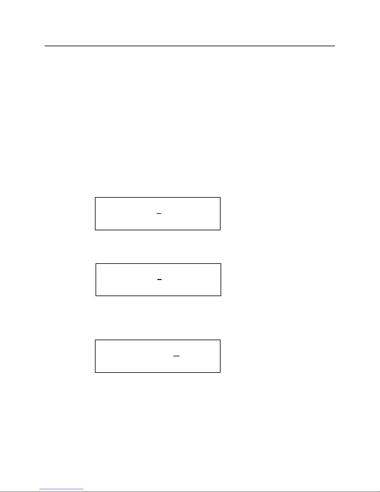
1. Press SCLK (Sample Clock) / FREQ (Frequency) button. Then, press double arrow button to
exchange the parameters.
The displayed frequency is either the power-on value or the previously selected
2. Enter the magnitude of the desired frequency.
Use the right-arrow button to place the cursor under the selected digit. Turn the knob to set the digit to
2. The frequency will indicate 12.00 kHz.
3. Select the desired frequency range.
Use the right-arrow button to place the cursor under the multiplier (k). Turn the knob counterclockwise
to switch the range by a decade.
1-3
FREQ= 10.00 kHZ
SCLK= 10.00 MHz
FREQ= 12.00 kHZ
SCLK= 12.00 MHz
FREQ= 1.200 k
HZ
SCLK= 1.200 MHz
Page 13
Chapter 1 Quick Start
To set the sample clock rate
To set the sample clock rate.
At the initial power-on, the generator outputs a free-running sine wave at 10kHz with an amplitude of
5.0 V peak-to-peak (into 50Ω termination) after the output is turned on. The following steps will show
you how to change the sample clock rate of a user-defined waveform or an optional sequence. The output frequency of any waveform is:
Waveform Frequency = [(Sample Clock) / (Waveform Length)]*(Number of Cycles in the Waveform Frame)
1. Press FUNC (function) key and select a user-defined waveform, WAV#. Select WAV#0 and press
ENTER.
The default length of a user-defined waveform is 2000 points.
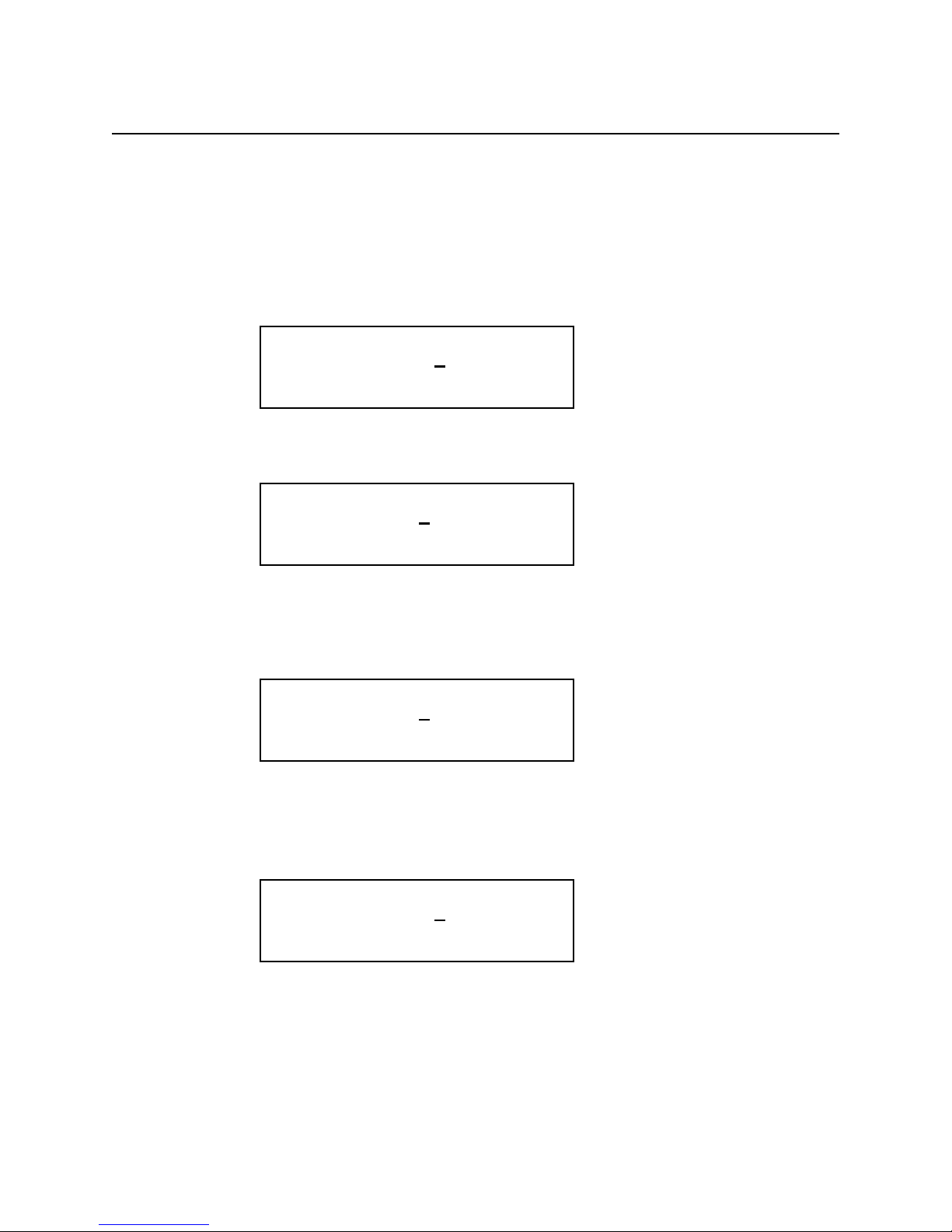
2. Press SCLK/FREQ (Sample Clock/Frequency) button.
The displayed sample clock is either the power-on value or the previous sample clock rate selected.
3. Enter the magnitude of the desired sample clock rate.
Use the right-arrow button to place the cursor under the selected digit. Turn the knob to set the digit to
2.
4. Select the range of the desired frequency.
Use the right-arrow button to place the cursor under the multiplier (M). Turn the knob counterclockwise
to switch the range by a decade. Observe the output frequency has changed by a decade.
1-4
SCLK= 10.00 MHZ
FREQ= 5.000 kHz
SCLK= 12.00 MHZ
FREQ= 6.000 kHz
SCLK= 1.200 MHZ
FREQ= 600.0 Hz
Page 14
Chapter 1 Quick Start
To set the output amplitude
To set the output amplitude
At the initial power-on, the generator outputs a cw sine wave at 10 kHz with an amplitude of 5V peakto-peak (into 50Ω termination) after the output is turned on. The following steps will show you how to
change the amplitude to 2.5V peak-to-peak.
1. Press AMPL/OFST (Amplitude/Offset) button.
The displayed amplitude is either the power-on value or the previous amplitude selected.
2. Select the digit you are going to modify.
Use the left-arrow button to place the cursor under the selected digit.
3. Enter the magnitude of the desired amplitude
Turn the knob counter clockwise to set the digit to 2.
4. Enter the magnitude of the desired amplitude.
Use the right-arrow button to place the cursor under the selected digit. Turn the knob to set the digit to 5
to change the magnitude.
1-5
AMPL= 5.000 V
OFST= 0.000 V
AMPL= 5.000 V
OFST= 0.000 V
AMPL= 2.000 V
OFST= 0.000 V
AMPL= 2.5
00 V
OFST= 0.000 V
Page 15
Chapter 1 Quick Start
To set the output offset voltage
To set the output offset voltage.
At the initial power-on, the generator outputs a cw sine wave at 1 kHz with an offset voltage of 0 V
(into 50Ω termination) after the output is turned on. The following steps will show you how to add 1.0
V offset to the output.
1. Press AMPL/OFST button twice or press the double arrow button to exchange the
parameters.
2. Select the digit and enter the desired offset voltage.
Use the left-arrow button to place the cursor under the number 0. Turn the knob to select the desired offset voltage. You must observe some restrictions for the magnitude of the offset voltage. The sum of the
offset and peak amplitude can not exceed ±5 volts when terminated with 50Ω.
1-6
OFST= 0.0
00 V
AMPL= 2.500 V
OFST = 1.000 V
AMPL = 2.500 V
Amplitude and DC Offset Ranges
TEGAM 2411B utilizes unique combinations of the input and output
attenuators for the output amplifier in order to accomplish the optimized
signal attenuation. Therefore, if DC offset is applied to the signal, the
following restrictions must be observed.
Amplitude Range
Legal Amplitude+DC Offset Limits
1V ~ 10.2V Amplitude + | DC Offset | < 10.4V
100mV ~ 999mV Amplitude + | DC Offset | <
1.00V
10mV ~ 99mV Amplitude + | DC Offset | <
100mV
Page 16

Chapter 1 Quick Start
To select a standard waveform
To select a standard waveform.
At the initial power-on, the generator outputs a free-running sinewave at 1 kHz after the output is turned
on. The following steps will show you how to select another standard waveform.
1. Press FUNC (function) button.
Select standard waveforms by pressing STDW (standard wave). The default length is set to 1000 points.
2. Use the right and left arrow buttons to view the selection menu.
Select one of the 20 standard waveforms.
3. Press SIN (sinewave) button to select parameter(s).
Use the double arrow button to exchange the parameters. Press the waveform button again to select
more parameters if available.
4. Turn the knob or key in the parameters on the 10-key to enter parameters.
1-7
FUNC:
wav# seq# STDW view
FUNC:STDW:
SIN squ tri saw+
FUNC:STDW:
am scm fm hsin
N=1.00 P=0.000
SIN squ tri saw+
Page 17

Chapter 1 Quick Start
To change the default length of standard waveform
To select a standard waveform (continued)
5. Press ENTER button to set parameters.
Note: the standard waveform data is recomputed after the parameters are changed. It may take a fraction of a second to several seconds to compute and draw the new waveshape. The time to draw the
waveform depends on the sample length and type of waveform selected.
To Change the default length of standard waveform.
The default length of 1000 points will create the maximum frequency of 2kHz sinewave. If higher frequency is required, the default length must be changed. The minimum length is 16 points.
1. Press SETUP button.
2. Press STDW (F2 soft key).
The display indicates standard waveform is located at the memory address of 10000 and the length is
1000. The 2411B automatically select the waveform memory location.
3. Press LEN (F4 soft key).
4. Turn the knob or key in the length on the 10-key to enter new length. Then, press OK (F3 soft
key).
1-8
SETUP:
WAV# STDW SEQ#
01000@10000 STDW
SYNC LEN
free=54504 L=1000
OK CANC
Page 18

Chapter 1 Quick Start
To select a user-defined waveform
To select a user-defined waveform.
At the initial power-on with the factory setting, the generator outputs free-running sinewave at 10 kHz
after the output is turned on. The following steps will show you how to select a user-defined arbitrary
arbitrary waveform. All user-defined waveforms must be created on the PC and downloaded to the
2411B using WaveWorks Pro or other software, or created using the edit utility prior to the selection.
However, we have loaded the first five user-defined waveform locations with sample waveforms for
your verification.
1. Press FUNC (function) button.
2. Press WAV# (F1 soft key).
If the waveform does not contain any data, it will not be displayed.
3. Press the knob to select one of the user-defined waveforms.
If the waveform does not contain any data, it will not be displayed.
4. Press ENTER button to select the user-defined waveform.
Whenever an asterisk is displayed on the LCD screen, the parameter selection is pending. You must
press ENTER button to complete the selection.
1-9
FUNC:
wav# seq# STDW view
*WAV# = 0
WAV# seq# stdw view
*WAV# = 2
WAV# seq# stdw view
WAV# = 2
WAV# seq# stdw view
Page 19

Chapter 1 Quick Start
To select a sequence waveform
To select a sequence waveform. (option)
The following steps will show you how to select a sequence waveform. The sequence generator option
must be installed in the 2411B prior to proceeding with the following steps. All user-defined waveforms
must be created on the PC and downloaded to the 2411B by using WaveWorks Pro or must be created
using the internal EDIT function before making the sequence selection. However, we have pre-loaded
the first five user-defined waveforms with the sample waveforms. We will utilize these waveforms to
demonstrate the sample sequence.
1. Press FUNC (function) button.
2. Press SEQ# (F2 soft key).
Turn the knob to select the desired Sequence waveform number. Press ENTER button. You will be able
to view the sequence waveform, unless you have already altered the sequence steps.
3. Turn the knob to select one of the user-defined waveforms.
If the sequence does not contain any data, it will not be displayed.
1-10
FUNC:
wav# seq# STDW view
*SEQ# = 0
wav# SEQ# stdw view
*SEQ# = 2
wav# SEQ# stdw view
Page 20

Chapter 1 Quick Start
To select a sequence waveform
To select a sequence waveform (continued)
4. Press ENTER button to select the sequence waveform.
Whenever an asterisk is displayed on the LCD screen, the parameter selection is pending. You must
press ENTER button to complete the selection.
Note: Each SEQ# may contain up to 4096 steps, use up to 1000 user-defined waveforms which may be
repeated up to 1,000,000 repetitions.
1-11
SEQ# = 2
wav# SEQ# stdw view
Page 21

Chapter 1 Quick Start
To select a operating mode
To select operating mode
The following steps will show you how to select an operating mode and output one cycle of a sinewavewhen a trigger signal is applied. The 2411B is initially set to CONT (continuous) mode.
1. Select a standard waveform.
See page 1-7 for the procedure.
2. Press MODE key to change the operating mode.
Press TRIG (F2 soft key) to select trigger mode.
3. Press ENTER button to select the mode.
Whenever an asterisk is displayed on the LCD screen, the parameter selection is pending. You must
press ENTER button to complete the selection.
4. Press SHIFT button and then press TRIG button (number 0 on 10-key) to output a single cycle
of a sinewave.
Please note the LED light will turn on when SHIFT button is pressed. While the SHIFT light is on, the
keypad will not function as a 10-keypad. Press again to disable the SHIFT button.
Note:
If you apply a single trigger pulse to the TRIG IN (TTL level) on the rear BNC connector, you can also
output a single cycle of a sinewave.
By selecting UTIL (UTILITY) button and then selecting TGEN (Trigger GENerator) (F4), you may
activate the internal trigger generator. When the internal generator is not in use, make sure that the triggert generator is set to OFF. Otherwise, it may interfere with other operation modes.
1-12
*MODE
cont TRIG gate brst
MODE:
cont TRIG gate brst
Page 22

Page 23

2
About Arbitrary W aveforms
Page 24
Chapter 2 About Arbitrary Waveforms
Waveform Generation
Waveform Generation
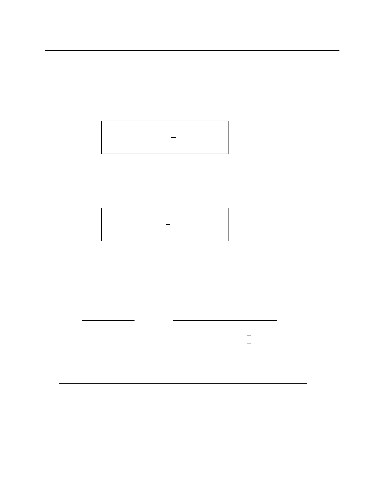
In an arbitrary waveform generator, you will define a waveform, using either the standard functions or
custom profile data files to load waveform memory. A set of start and stop addresses which correspond
to a waveform memory location is assigned with a waveform number. An address generator sequentially
presents data values from the specified memory location to the digital-to-analog converter (DAC). The
precision DAC converts the data into analog voltage values. This series of sequential voltage levels
describes the output waveform with the frequency determined by the sample clock rate divided by the
number of samples in the waveform. Changing the sample clock rate causes the address generator to
change the speed at which the data is presented to the DAC, thereby changing the output frequency.
The waveforms you create are a series of data points consisting of X- and Y-axis values. For 16-bit generators, such as the TEGAM 2411B, the Y values between +32767 and -32768 are used. In describing
the first point, 0, is given a Y value. The next point has another Yvalue, and so on up to the last address
in your waveform. This series of points make up the waveshape.
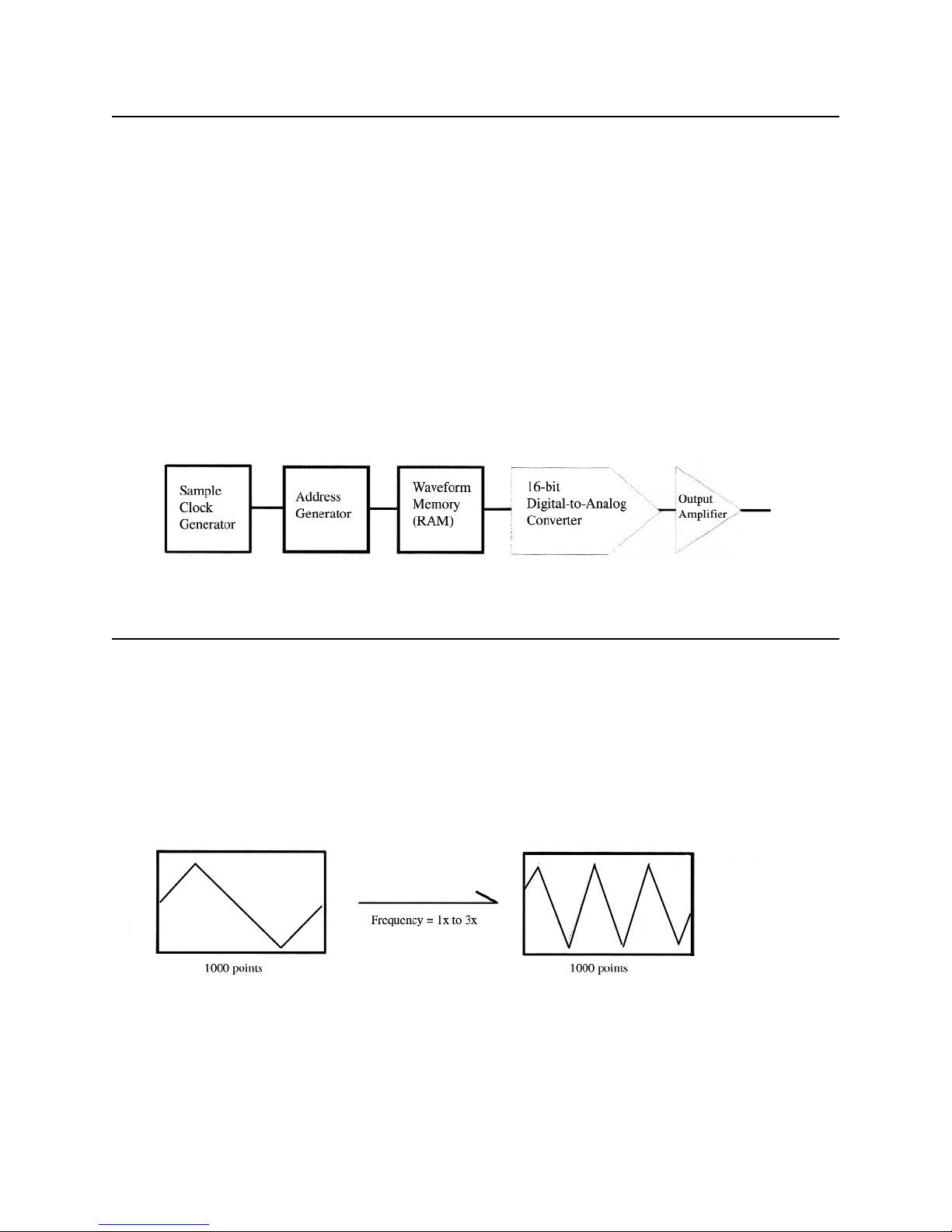
Waveform Cycle
All the data points in the specified waveform memory location make up one waveform cycle. The waveform generator will output all the points in the waveform at the sample clock rate specified. The resulting frequency is equal to the sample clock rate divided by the number of data points in the waveform. If
more than one cycle of the waveshape is entered into a waveform, the output frequency will be a multiple of one waveform generator cycle. For example, if you create a waveform with 3 triangle wave cycles
using the same number of data points and the sample clock rate, the frequency will be 3 times higher.
2-2
Page 25

Chapter 2 About Arbitrary Waveforms
More on Waveform Cycle
More on Waveform Cycle
TEGAM’s 2411B arbitrary waveform generator may sample the data points up to a maximum of 2
MS/s. The maximum frequency of the output is determined by the sample rate divided by the number of
points. For a 2 MHz arbitrary waveform generator with a waveform length of 1000 points, the upper frequency limit appears to be 2 kHz, since 2 MS/s / 1000 = 2 kHz. However, if you repeat the segment,
such as a sinewave, up to the minimum required number of samples (4 samples/segment), you can replicate up to 250 segments within the waveform length of 1000 points. Then, the output frequency of the
sinewave will be 500 kHz, since 2 kHz x 250 = 500 kHz.
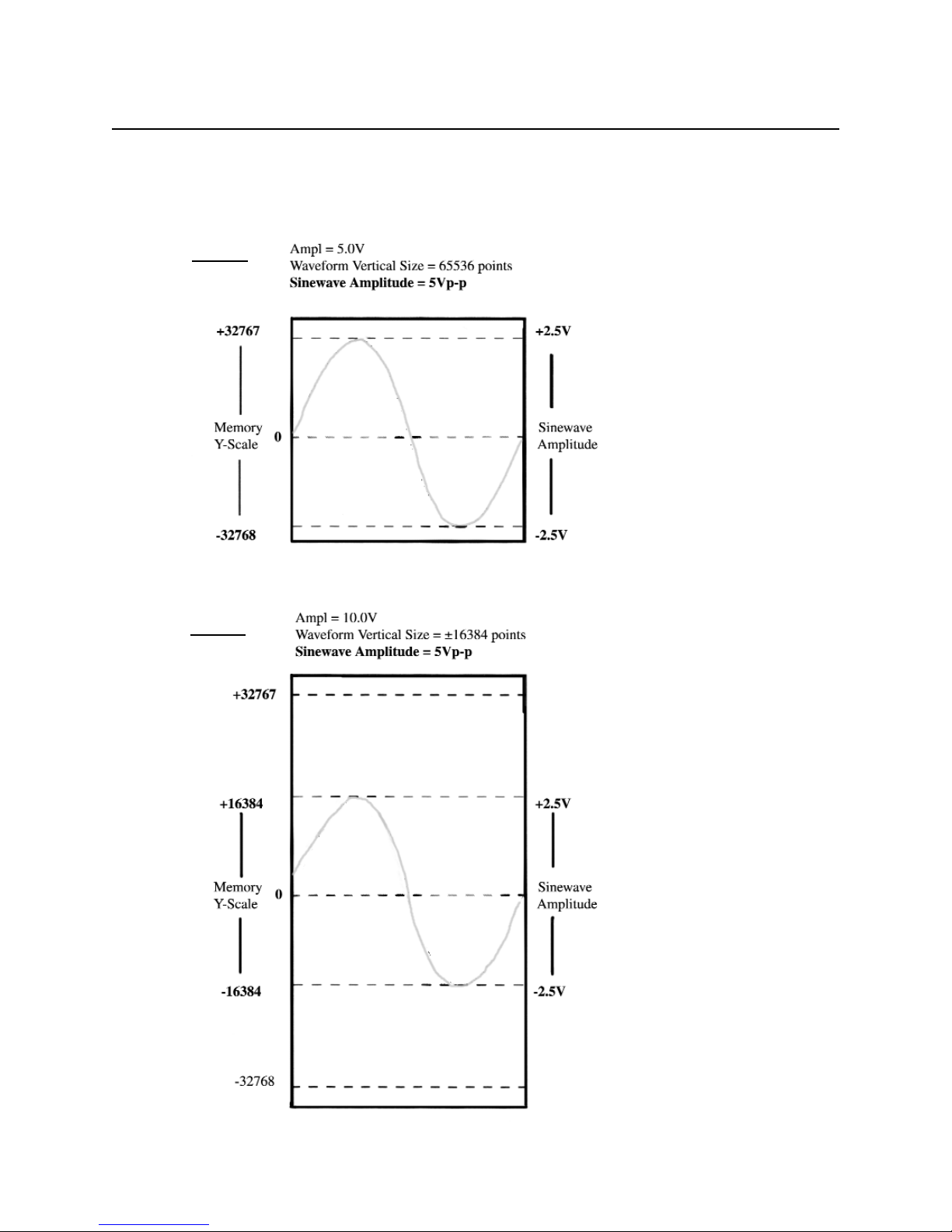
Digital and Analog Scaling
Whenever possible range the Y-values of a waveform between -32768 to +32767 in the memory to
obtain maximum resolution and to maintain the desired dc integrity of the signal. WaveWorks Pro allows
you to normalize any waveform in its Y values by a simple command. For instance, if you have a
sinewave in the waveform window that ranges from -32768 to +32767 you can specify the output at 5
volts peak-to-peak. Automatically the -32768 relative amplitude will be scaled to -2.5 volts and the
+32767 relative amplitude will be scaled to +2.5 volts. The sinewave will be centered around zero volts.
The desired output voltage may be set on the front panel of the generator or on the Download Setup
form before the waveform is sent to the 2411B. If you set the output amplitude to 10 volts peak-to-peak
and then you download a waveform with Y-values between +16384 and -16384, you have the same
+/-2.5 volt sinewave output. It is very important to understand the differences between digital scaling
and analog scaling. See the following page for the illustration.
Other Considerations
The Y values of the starting and ending points in your waveform can cause unexpected discontinuities if
they are not the same value. The waveform generator output will jump from the ending value to the
starting value of each cycle. If you are using the sequence generator in an arbitrary waveform generator,
the ending value of a waveform will jump to the starting value of the next waveform in the sequence.
For a smooth, transient-free waveform output, be sure the starting and ending values are the same for a
single waveform and the starting and ending values of adjacent waveforms are the same for a
sequenced waveform.
2-3
Page 26
Chapter 2 About Arbitrary Waveforms
Examples - Digital and Analog Scaling
Examples - Digital and Analog Scaling
Both case 1 and case 2 produce the same output amplitude with different
vertical resolution.
2-4
Case 1
Case 2
Page 27

Chapter 2 About Arbitrary Waveforms
Waveform Types
Waveform Types
TEGAM 2411B arbitrary waveform generators can create two types of waveforms, namely standard
waveforms and user-defined waveforms. In addition, if you have installed the optional Sequence
Generator in the 2411B, you may loop and link up to 100 user-defined waveforms.
Standard Waveforms
You may access 20 commonly used standard waveforms from the front panel. These waveforms are not
available for the sequence generator from the front panel.
User-defined Waveforms (Arbitrary Waveforms)
You must create user-defined waveforms on a PC and download them to the memory of the 2411B or
you must create them using the EDIT mode. You may use the optional WaveWorks Pro + software to
create user-defined waveforms. User-defined waveforms are utilized to create sequence steps in the
optional sequence operation.
Sequence Waveforms (Optional)
You can create a virtual waveform using the user-defined waveforms in the waveform memory and
repeating the waveforms any number of times without increasing the size of the waveform memory.
Each step is defined with one of the user-defined waveforms and the number of repetition of this waveform. You may create up to 1000 steps utilizing up to 100 user-defined waveforms in each sequence
waveform.
Waveform Memory
Sequenced Waveform
Example:
Step 1) WAV#02, 2 times; Step 2) WAV#01, 1 time; Step 3) WAV#03, 3 times
2-5
Page 28
Chapter 2 About Arbitrary Waveforms
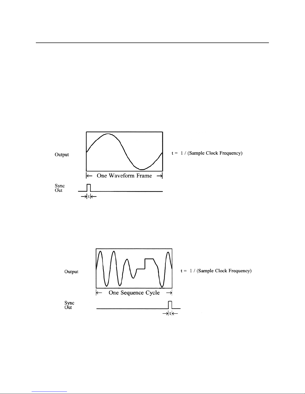
Sync Pulse
Sync Pulse
Four sync pulses are provided to synchronize the generator output waveform to trigger an external system, such as an oscilloscope.
For standard and user-defined waveforms, the sync pulse is typically placed at the start
of the waveform frame. For sequence waveforms, the sync pulse is placed at the end to indicate
the sequence completion. The detail description of the programmable sync is given in chapter 8.
Standard and User-defined Waveforms
Sequence Waveforms
Note:
If you programmed only one step in a sequence, the sync pulse appears at the start of the
waveform.
2-6
Page 29

Chapter 2 About Arbitrary Waveforms
Sync Outputs
Sync Outputs
The 2411B is unique in having extremely flexible sync waveform features. Each of the four
sync signals may be programmed via the remote interfaces to any binary valued pattern equal in
length to the waveform with which each is associated. The electrical outputs are all TTL.
In addition to providing virtually infinite pattern flexibility using the remote programming interfaces, the
sync signals have a second set of functional features. Each of the following sync signals may be programmed from the front panel or from the remote interface.
Sync 1 - Is located on the front panel where it may be set to End Pulse (a pulse of sample clock duration
occurring during the last sample of the waveform), or be set to Programmable Address (a pulse having a
start address and a length).
Sync 2 - Is located on the rear panel where it may be set to Programmable Address ( a pulse having a
start address and a length). Sync 2 has no secondary function.
Sync 3 - Is located on the rear panel where it may be set to Run (a high-level during the period of time
the waveform is being samples), or be set to Programmable Adddress (a pulse having a start address and
a length.)
Sync 4- Is located on the rear panel where it may be set to End Block (a pulse of sample clock duration
occurring during the last sample of each step in the sequence), or be set to Programmable Address (a
pulse having a start address and a length).
2-7
CAUTION: Remotely programmed sync
patterns are overwritten if the user uses
the front panel to edit the sync signal.
Page 30

Page 31

Chapter 2 About Arbitrary Waveforms
2411B Block Diagram
2-8
Block Diagram
Page 32

3
Front-Panel Menu Operation
Page 33

Chapter 3 Front-Panel Menu Operation
Parameter Control
Parameter Control
A: MODE menu
1. CONT (Continuous): Select the continuous waveform output.
2. TRIG (Trigger): Select the triggered waveform output. Output one waveform
frame when a trigger signal is applied.
3. GATE: Select the gated waveform output. Output multiple waveform
frames as long as the trigger input signal is high or the manual
button is pressed down.
4. BRST (Burst): Select the burst mode. Output multiple number of waveform
frames set by the burst cycle parameter when a trigger signal is
applied. The number of burst cycles may be set between 1 and
1,048,575.
Note: The Burst mode is not available for sequence wave form.
5. TOGL (Toggle): Select the toggle mode. Output multiple waveform frames when a
trigger signal is applied and then return to the quiescent state when the
second trigger signal is applied.
B: CLOCK/FREQ menu
1. CLOCK (Sample Clock) Sets the sample clock rate of the waveform frame.
CLOCK (Sample Clock) applies for WAV#, SEQ# and STDW.
2. FREQ (Frequency) Set the frequency of the waveform frame.
FREQ (Frequency) applies for WAV# and STDW only.
C: AMPL/OFSTmenu
1. AMPL (Amplitude) Sets the amplitude of the waveform frame.
2. OFST (Offset) Set the dc offset voltage of the waveform frame.
Note: See Chapter 2 to review the digital amplitude and offset settings.
3-2
1: CONT 2: TRIG 3: GATE 4: BRST 5:TOGL
Page 34

Chapter 3 Front-Panel Menu Operation
Parameter Control (continued)
D: FUNC (Function) menu
1: WAV# Select a user-defined arbitrary waveform by the waveform number (0~99).
2: SEQ# Select a user-defined sequence waveform by the sequence number (0~99).
3: STDW Select a standard waveform.
4: VIEW Select the left and right memory addresses to view the waveform memory
contents. You may specify and select ALL, SEG1, SEG2 or SEG3.
Note: The sequence generator option must be installed to select sequence waveforms.
Sequence waveform is not available in burst mode.
D3: STDW (Standard Waveform)
1: SIN (Sine) Select sine wave.
2: SQR (Square) Select square wave.
3: TRI (Triangle) Select triangle wave.
4: SAW+ (Sawtooth+) Select positive-going ramp wave.
5: SAW- (Sawtooth-) Select negative-going ramp wave.
6: DC Select DC level.
7: EXP+ (Exponential+) Select positive-going exponential wave.
8: EXP- (Exponential-) Select negative-going exponential wave.
9: AM Select AM (Amplitude Modulation) wave.
10: SCM Select SCM (Suppressed Carrier Modulation) wave.
11: FM Select FM (Frequency Modulation) wave.
12: HSIN (Haversine) Select haversine wave.
13: SUN (Sweep Linear) Select linear sweep wave.
14: SLOG (Sweep Log) Select log sweep wave.
15: PLS+ (Pulse+) Select positive-going pulse wave.
16: PLS- (Pulse-) Select negative-going pulse wave.
17: GAUS (Gaussian Pulse) Select Gaussian pulse wave.
18: SX/X (Sine X/X) Select (sine x)/x (or SINC) wave.
19: CIRC (Circular) Select semi-circular wave.
20: NOIS (Noise) Select random noise wave.
3-3
1: WAV# 2: SEQ# 3: STDW 4: VIEW
1: SIN 2: SQR 3: TRI 4: SAW+ 5: SAW- 6: DC 7: EXP+ 8: EXP9: AM 10: SCM 11: FM 12: HSIN 13: SLIN 14: SLOG 15: PLS+ 16: PLS-
17: GAUS 18: SX/X 19: CIRC 20: NOIS
Page 35

Chapter 3 Front-Panel Menu Operation
Waveform Setup
E: OUTPUT menu
1: ON Turn the generator output on.
2: 40K Turn 40kHz low pass filter on.
3: 700K Turn 700kHz low pass filter on.
4: SYNC Select the sync mode of SYNC 1, SYNC 3 and SYNC 4.
5: STRG (Sync Trigger) Select sync trigger operation mode (Series or Parallel)
6: DEGL (Deglitcher) Turns on or off deglitcher.
Waveform Setup (Refer to Chapter 4 for detail operations.)
SETUP menu
1: WAV# (Waveform Number) Select, allocate or delete a user-defined waveform and set up
the waveform length and the parameter of 4 sync pulses.
2: STDW (Standard Wave) Select the standard waveform and set up the length and the
parameter of 4 sync pulses.
3: SEQ# (Sequence Number) Select, create or delete a sequence waveform and edit the
sequence steps.
Waveform Edit (Refer to Chapter 4 for detail operations.)
EDIT menu
1: LINE Line mode creates a line segment of a user-defined waveform using
START, ANCHOR and CHORD commands.
2: VRTX (Vertex) VRTX (Vertex) mode creates a user-defined waveform using two anchor
points and a vertex. This mode allows to insert a standard function, and
scale and offset a portion of the waveform.
3: MATH Math mode allows the user to mathematically operate on existing
waveforms. Addition, subtraction and multiplication are available on two
selected user-defined waveforms.
3-4
1: WAV# 2: STDW 3: SEQ#
1: ON 2: 40K 3: 700K 4: SYNC 5: STRG 6: DEGL
1: LINE 2: VRTX 3: MATH
Page 36

Chapter 3 Front-Panel Menu Operation
System Control
System Control
A: UTIL (Utility) menu
1: SCLK Select the sample clock source.
2: RCLK Select the reference clock source and make a fine adjustment to the
internal reference clock.
3: TGIN Select the trigger type for multi-phase or single unit operations.
4: TGEN Select the internal trigger generator and the trigger rate.
5: MBST Select and display the monitor burst count.
6: GPIB Set the GPIB bus address (0-30).
7: R232 Set the RS232 serial interface parameters.
B: LOCAL Select the front panel control when the instrument is in remote
mode. Press SHIFT
button and then press LOCAL (or number 8 key)
C: STOR/RECL Store and recall 31 sets of the 2411B status. Press ENTER to activate the recalled set
tings.
D: RESET Reset the 2411B. Press SHIFT button and then press RESET (or number 9 key). Select
either ALL or CURR.
E: RTS Return to start address. Press SHIFT button and then press RTS (or number +/- key).
F: HOLD Hold the output at the current level until released. Press SHIFT button and then press
HOLD.
G: TRIG Manual trigger button. Initiates GATE, TRIG, BURST and TOGGLE mode.
H: LCD Adjust the LCD screen viewing angle. Press SHIFT button and
then press LCD. Turn knob to adjust viewing angle.
3-5
1: SCLK 2: RCLK 3: TGIN 4: TGEN 5: MBST 6: GPIB 7: R232
Page 37

Chapter 3 Front-Panel Menu Operation
Default Settings
Default Settings
Important: by holding RESET key (or number 9 key on the 10-key pad) down while turning the
LINE switch on, you can reset the 2411B settings to the factory defaults. If you want to save the wave-
form data, be sure to back up in a PC using WWP Pro + or an appropriate software before resetting the
2411B.
Front-panel button Defaults
UTILity Defaults
3-6
Buttons Factory Defaults
MODE CONT
FUNC STDW (SIN)
CLOCK
FREQ
SCLK=1.000MHz
FREQ=1.000kHZ
AMPL
OFST
AMPL=5.000 V
OFST=0.000 V
OUTPUT output and filters off
Buttons Defaults
SCLK INT
RCLK INT
TGIN ASYNC
MBST n=3
GPIB GADR=16
TGEN
OFF
R232
BAUD=1.2K,
PAR=NONE,
BITS=8D1S
HAND=SW
Page 38

Chapter 3 Front-Panel Menu Operation
Default Settings (continued)
Default Settings (continued)
User-Defined Waveform Defaults
Optional Sequence Waveform Defaults
3-7
WAV#
SIZE
Type
Sync Location
1 2 3 4
0
2000
Triangle
0 0 0 0
1
2000
DC 0V
0 0 0 0
2
2000
Pulse
0 0 0 0
3
2000
DC 0V
0 0 0 0
4
2000
DC 0V
0 0 0 0
SEQ# Step WAV# Repeat
0
10 0 2
20 2 1
30 0 3
1
10 1 2
20 3 4
30 4 6
2
50 1 2
60 3 4
70 4 6
Page 39

Chapter 3 Front-Panel Menu Operation
Default Settings (continued)
Standard Waveform Default Settings (continued)
Default settings are listed in the following tables. The limits are shown in parenthesis.
3-8
Function Parameters Range Defaults
Sine (SIN)
Phase 0.000~360.000° 0.000°
Number of Cycles 0.01~1000.00 1.00
Square (SQU)
Number of Cycles 1 ~ 1000 1
Duty Cycle 1~100% 50%
Triangle (TRI) Number of Cycles 1 ~ 1000 1
Number of Cycles 1~1000 1
Sawtooth
(SAW+/-)
Duty Cycle 1~100% 100%
DC
DC -32768~
+32767
0
Exponential
(EXP+/-)
Time Constant 0.01~20.00 5
Amplitude
Modulation
(AM)
Carrier Frequency 1~10000 20
Modulation 1~10000 1
Modulation Index 0~200% 100%
Modulation Phase 0~360° 0°
Carrier Phase 0~360° 0°
Suppressed
Carrier
Modulation
(SCM)
Carrier Frequency 1~1000 20
Modulation Freq. 1~1000 1
Modulation Phase 0~360° 0°
Carrier Phase
0~360° 0°
Haversine
(HSIN)
Number of Cycles
0.01 ~ 1000.00
1.00
Linear Sweep
(SLIN)
Begin 1 ~ 1000 1
End 1 ~ 1000 10
Log Sweep
(SLOG)
Begin 1 ~ 1000 1
End 1 ~ 1000 10
Pulse
(PLS+/-)
Delay 0~100% 0%
Rise Time 0~100% 10%
High Time 0~100% 30%
Fall Time 0~100% 10%
Number of Cycles 1~1000 1
Gaussian
(GAUS)
Exponent 0.01 ~ 20.00 2
Sine X/X (SX/X)
Number 4.00 ~ 1000.00 5.50
Circle (CIRC)
Number of Cycles 0.01 ~ 1000.00 1.00
Phase 0.01 ~ 360.00° 0.00°
Page 40

Chapter 3 Front-panel Menu Operation
Standard Waveform List
Standard Waveform List
The following list shows you the standard waveforms available from the 2411B front panel and in the
optional WaveWorks Pro software. You can create a standard waveform in WaveWorks Pro and download it to an arbitrary waveform location. Now, you can select the customized standard waveform from
the front panel as a user-defined waveform.
3-9
2411B
WaveWorks Pro
Sine
Square
Triangle
Sawtooth (+/-)
DC
Exponential (+/-)
AM
SCM
FM
Haversine
Linear Sweep
Log Sweep
Pulse (+/-)
Gaussian
Sine(X)/X
Circle
Noise
Sine Cosine
Square Squine
Triangle Lines
Ramp Steps
DC Binary FSK
Exponential Binary PSK
AM NTSC
SCM PAL
FM PWM
Pulse1 VHR Pulse
Cont Sweep Burst Sweep
Step Sweep Digital Noise
Pulse 2 FIR_LPF
Gaussian Han(SinX/X)
Sin(X)/X Comb
Cardiac
Analog Noise
Page 41

4
Waveform Creation System
Page 42

Chapter 4 Waveform Creation System
Components
Components
The following components are required for the 2411 B waveform creation system.
• Model 2411B Arbitrary Waveform Generator
• WaveWorks Pro + Wavform Creation Software
• RS-232 Cable
It is recommended that you install the optional WaveWorks Pro + in a PC equipped with the following
minimum configuration. For more details, see page 1-3 of the WaveWorks Pro manual.
• IBM (or compatible) PC , 16MB memory
• 2MB free harddisk space. Windows 95 or higher operating system
Recommendation
It is recommended that you try operating WaveWorks Pro + software using the PC
asynchronous serial port (COM port) since you do not have to have the specified
GPIB card and software installed in your PC. Follow the installation instruction
on page 1 -4 of the WaveWorks Pro + manual.
User Interface
When the system is completely installed, the following interfaces are used to
control the waveform creation system.
Front Panel (2411B)
This is used primarily to select and control the hardware parameters, such as mode, sample clock rate,
amplitude, offset, and waveform selection. 20 standard waveforms may be created from the front panel.
Arbitrary waveforms and sequence waveforms can be edited from the front panel.
Waveform Windows (WaveWorks Pro +)
The WaveWorks Pro +, which runs under Windows, is the main interface for waveform creation tasks.
You can create up to 32 standard waveforms and unlimited number of arbitrary and sequence waveforms
using Point Edit and Waveform Math.
You may also analyze and edit the waveforms using the FFT and Digital Pattern Generator while
exchanging the ASCII data with other applications. Once the communications link is established
between the PC and the waveform generator, downloading a waveform is as simple as selecting the
download waveform location and clicking the OK button.
4-2
Page 43

Chapter 4 Waveform Creation System
User Interface for the Waveform Creation System
4-3
Page 44

Chapter 4 Waveform Creation System
Memory Organization-Introduction
Memory Organization
Introduction
This section explains how the waveform memory is organized, the system of waveform numbering, how
default memory segments can be changed, and how standard functions can be inserted.
Default Partitioning
The total available waveform memory is 65,504 points. The memory is initially divided into partitions to
provide easy programming of 6 different waveforms. Five blocks of 2000 points each occupy the first
10K of memory. In addition, one of 20 standard waveforms can be readily recalled from the Function
menu and downloaded to 1000 points of memory from 10k to 11k. (A sinewave is the default Standard
Wave.)
Waveform Numbering
The first 5 blocks of memory are assigned Waveform Numbers. Additional Waveform Numbers can be
assigned (up to total of 100, depending on the number of points). Waveform Numbers are used to access
the memory blocks for initial waveform programming and to recall the waveforms later. Waveform
Numbers are arrayed in the memory in ascending order. Figure below shows the default waveform numbers and partitioning.
Waveform Numbers and Memory Partitions
Changing Waveform Block Length
Standard Wave
The standard wave memory can be changed from its default value of 1000 points. (Minimum
waveform length is 16 points.)
4-4
START START START START START START START
0 2000 4000 6000 8000 10000 11000
WAV#0 WAV#1 WAV#2 WAV#3 WAV#4 STDW Avaiable MemorySpace
System
1999 3999 5999 7999 9999 10999 65503
65535
Stop Stop Stop Stop Stop Stop Stop
Page 45

Chapter 4 Waveform Creation System
Memory Organization-Waveform Number Block Lengths (continued)
Memory Organization-Changing Waveform Block Length (continued)
1) Press SETUP key.
2) Press STDW softkey (F2). The display indicates the present length of the standard wave and
the address where it begins in memory.
3) Press LEN softkey (F4). The display indicates the available free memory.
4) Select desired standard wave length with edit knob or keypad. (Do not attempt to exceed the
amount of memory available.)
5) Press OK (F3) to enter change or CANC (F4) to cancel.
6) Press ENTER.
Waveform Number Block Length
The waveform length of the numbered blocks can be changed from their default values of 2000
points. (Minimum waveform length is 32 points.)
1) Press SETUP key.
2) Press WAV# softkey (Fl).
3) Select Waveform Number with edit knob. The display indicates the present length and start
address of the waveform.
4) Press LEN softkey. The display indicates the available free memory.
5) Select desired waveform block length with edit knob or keypad. (Do not attempt to exceed
the amount of memory available.)
6) Press OK to enter change or CANC to cancel.
Deleting Waveform
A waveform which is no longer needed can be deleted from memory as follows:
1) Press SETUP key.
2) Press WAV# softkey.
3) Select Waveform Number with edit knob.
4) Press DEL softkey.
5) Press OK to delete or CANC to cancel.
Inserting New Waveform Numbers
Unused Waveform Numbers can be activated as follows:
1) Press SETUP key.
2) Press WAV# softkey.
3) Press NEW softkey.
4) Screen will show all unused Waveform Numbers when edit knob is turned. Select desired
number.
5) Move waveform length to right side of display with double-arrow key and set desired length
with edit knob or keypad.
(New waveform cannot be longer than available free memory.)
6) Press OK to insert new Waveform Number or CANC to cancel.
4-5
Page 46

Chapter 4 Waveform Creation System
Waveform Creation using Front Panel-Introduction
Waveform Creation using Front Panel
Introduction
This section explains how to create arbitrary, non-standard waveshapes. These custom waveforms can be
created a segment at a time using LINE or VERTEX edit modes. Each step in the waveform construction may be viewed on an oscilloscope connected to the instrument output. Arbitrary and standard
waveforms can be interspersed. More complex waveforms can be created by adding, subtracting, and
multiplying any two standard or arbitrary waveforms that have been previously stored in memory.
NOTE: Define waveform number block length before creating an arbitrary waveshape.
Line Mode
With the line editing mode, waveforms are created a segment at a time from a left-hand start or anchor
point. Aline is drawn from the start point or anchor to a "vertex" point which is positioned to the right.
The vertex becomes a new anchor and the process is interactively repeated until the new arbitrary waveform is completed. This process is illustrated in page 4-8. All or any portion of a selected waveform
block can be edited. Editing begins at the start point. Astart point can be placed at any X and Y position
within the selected waveform block. Alternatively, a left anchor can be positioned at any X address, but
the Y value follows that of any previously programmed waveform (or baseline if no waveform was programmed).
Editing From Start Point
1) Press EDIT key.
2) Press LINE softkey (Fl).
3) Select Waveform Number using edit knob or keypad (press ENTER after using keypad).
4) Arbitrary waveform construction can begin at any point within the selected waveform number
block. Press STRT softkey (Fl).
5) Use edit knob or keypad to select X and Y addresses to start waveform editing within the
selected block. Use double-arrow key to move each active parameter to right side of display.
(Remember to press ENTER if keypad is used.)
6) Press OK (F3) to store start point or CANC (F4) to cancel.
7) Press ANCH softkey (F2).
8) Use double-arrow key to move Right Anchor (AR) to right side of
4-6
Page 47

Chapter 4 Waveform Creation System
Waveform Creation using Front Panel-Line Mode
Line Mode (continued)
LCD. Use edit knob or keypad to select X address for the end of the
edited portion of the waveform.
9) Press OK (F3) to store right anchor or CANC (F4) to cancel.
Editing From Left Anchor
1) Press EDIT key.
2) Press LINE softkey (Fl).
3) Select Waveform Number using edit knob or keypad (press ENTER after using keypad).
4) Arbitrary waveform construction can begin at any X address within the selected waveform num-
ber block. Press ANCH soft key (F2). (If the Start Point is to be uniquely defined, see previous
section.)
5) Use double-arrow key to move Left Anchor (AL) to right side of display. Use edit knob or keypad to select X address. (Remember to press ENTER if keypad is used.)
6) Use double-arrow key to move Right Anchor (AR) to right side of LCD. Use edit knob or key-
pad to select X address for the end of the edited portion of the waveform.
7) Press OK (F3) to store anchors or CANC (F4) to cancel.
Creating Line Segments
1) Press CHRD (chord) softkey (F3). (Set anchors first per previous section.)
2) Use edit knob, keypad or optional mouse to select X and Y addresses for the destination of the
first line segment (chord). If the mouse is used, LCD readouts will continually indicate mouse
position.
3) When the desired position is reached, press OK (F3) and the line segment will be stored. Press
CANC (F4) to cancel.
4) Create the next line segment by again using the knob or keypad to set the next X-Y coordinate,
as before.
5) Continue adding line segments up to the limit established in step 5 of Editing from Start Point
section.
4-7
Page 48

Chapter 4 Waveform Creation System
Waveform Creation using Front Panel-Line Mode
Line Mode Waveform Creation and Editing
4-8
Page 49

Chapter 4 Waveform Creation System
Waveform Creation using Front Panel-Vertex Mode
Vertex Mode
With the vertex editing mode, waveforms are created by establishing two anchor points at selected
addresses, positioning a vertex in the active region between the two anchors and then connecting the
vertex to the anchors with two line segments. The vertex mode also permits waveform scaling and the
insertion of standard functions. Vertex editing is illustrated in page 4-10.
1) Press EDIT key.
2) Press VRTX softkey (F2).
3) Select Waveform Number using edit knob or keypad (press ENTER after using keypad).
Selecting Left and Right Anchor Points
1) Press ANCH softkey (F3).
2) Set left anchor (AL) X value using edit knob or keypad. Press ENTER if keypad is used.
3) Use double-arrow key to move right anchor (AR) to right side of LCD. Set right anchor X
value using edit knob, keypad or optional mouse.
4) Press OK (F3) to store anchors or CANC (F4) to cancel.
NOTE
The difference between the left and right anchors is limited to 8000
points or the waveform length, whichever is less.
Selecting Vertex Point
1) Press ADDV softkey (Fl).
2) Set vertex X and Y values using edit knob, keypad or optional mouse.
3) When the desired position is reached, press OK (F3) and the two line segments will be
stored. Press CANC (F4) to cancel.
4) Continue adding anchors and vertices until the waveform is completed.
Scaling
Scaling allows any portion of a waveform designated by the left and right anchors to be scaled in
amplitude and offset.
1) Select anchors as in page 4-6.
2) Press SCAL softkey (F2).
3) Set digital amplitude (DA) and digital offset (DO) values for selected portion of waveform
using edit knob or keypad. Observe changes on output oscilloscope. Use double-arrow key to
select active parameter.
4) Press OK (F3) to store the scaled waveform or CANC (F4) to cancel.
4-9
Page 50

Chapter 4 Waveform Creation System
Waveform Creation using Front Panel-Vertex Mode
Vertex Mode Waveform Creation and Editing
4-10
Page 51

Chapter 4 Waveform Creation System
Waveform Creation using Front Panel-Vertex Mode
Vertex Mode (continued)
NOTE
The digital amplitude default value is 65535. The
available range of settings is ±131071. A negative
setting inverts the edited waveform portion. Rescaling amplitude from the default value of 65535
to the maximum value of 131071 doubles the output
amplitude. Steps 1-4 above can be repeated as
necessary to enlarge small signals.
CAUTION
The waveform will be clipped if the scaling factors
exceed the 65535 points available in the waveform
memory.
Smoothing
A smoothing factor may be applied to any part or all of a waveform. It is computed as a moving average
over a specified number of samples.
1) Select anchors as in Selecting Left and Right Anchor Points section.
2) Press either the left or right arrow key.
3) Press SMOO softkey (F3).
4) Select the number of samples to be averaged (up to 250) using the edit knob or keypad.
5) Press SHOW softkey (F2) to preview.
6) Press CANC softkey (F4) to cancel.
7) Press OK softkey (F3) to store smoothed waveform.
Inserting Standard Functions
Any one of 20 standard functions can be inserted between the left and right anchors.
1) Select anchors as in Selecting Left and Right Anchor Points section.
2) Press INSF softkey (F4).
3) Select desired standard waveshape by pressing softkey. Use left and right arrow keys to view
all 20 waveshapes. Access any desired ancillary functions by pressing the right arrow (->)
softkey (Fl).
4) Press SHOW softkey ( F2) to preview selection.
5) Press CANC softkey (F4) to cancel selection.
6) Press OK softkey (F3) to store selection.
4-11
Page 52

Chapter 4 Waveform Creation System
Waveform Creation using Front Panel-Vertex Mode
Vertex Mode (continued)
Summing Standard Functions
Any one of the 20 standard functions can be algebraically summed to any part
or all of any other standard function.
1) Select the first standard waveshape as in previous section.
2) If the second standard waveshape is to be summed to only a portion of
the first standard waveshape, reposition the anchors as described in
previous section.
3) Press either the left or right arrow key.
4) Press SUMF softkey (Fl).
5) Select desired standard waveshape by pressing softkey. Use left and right arrow keys to
view all 20 waveshapes. Access any desired ancillary functions by pressing the --> softkey
(Fl). (Reduce the digital amplitude value as necessary to prevent clipping.)
6) Press SHOW softkey (F2) to preview summed waveforms.
7) Press CANC softkey (F4) to cancel.
8) Press OK softkey (F3) to store summed waveforms.
Dump Function
Dump Function permits a standard waveform to be conveniently loaded into the entire length of
a Waveform Number without specifying left and right anchors. Thus, standard waveforms can
be inserted in Waveform Numbers with lengths greater than 8000 points.
1) Select the desired Waveform Number.
2) Press either the left or right arrow key.
3) Press DMPF softkey (F2).
4) Select desired standard waveshape by pressing softkey. Use left and right arrow keys to
view all 20 waveshapes. Access any desired ancillary functions by pressing the --> soft
key (Fl).
5) Press DO softkey (F2) to store the waveform in memory and permit further changes or
press OK softkey (F3) to store waveform and return to previous menu.
CAUTION
It is not possible to preview a function when
using Dump Function. Both the DO and OK
commands above will cause the new waveform to write over any previous waveforms.
4-12
Page 53

Chapter 4 Waveform Creation System
Waveform Creation using Front Panel-Math Operations
Waveform Creation using Front Panel-Vertex Mode (continued)
Move
The Move commands allow a section of a waveform as defined by the left and right anchors to
be copied and pasted into another section of the same or another Waveform Number.
1) Select the desired Waveform Number.
2) Press either the left or right arrow key.
3) Press MOVE softkey (F4).
4) Set left and right anchors to the waveform section to be copied.
5) Press COPY softkey (Fl).
*6) Press LAST key.
*7) Set Waveform Number to receive pasted section.
*8) Press MOVE softkey (F4).
9) Set left and right anchors to the destination waveform section.
10) Press PSTE softkey (F2).
* These steps may be omitted if copy and paste are within the same Waveform Number.
NOTE
The pasted waveform will be truncated if the destination
waveform section has fewer points than the original.
Math Operations
Math operations permit the contents of any two Waveform Numbers of equal size to be algebraically
added, subtracted or multiplied together. Complex composite signals can thus be created, such as shaped
tone bursts, amplitude modulation, etc. To enter the Math Mode:
1) Press EDIT key.
2) Press MATH softkey (F3).
Selecting Math Function
The three math functions have the following forms:
A*B (Multiply; output amplitude normalized to full-scale waveform memory.)
A+B (Add; output amplitude divided by two.)
A-B (Subtract; output amplitude divided by two.)
4-13
Page 54

Chapter 4 Waveform Creation System
Waveform Creation using Front Panel-Examples
Waveform Creation using Front Panel-Math Operation (continued)
To select one of the math functions:
1) Press OP softkey (F2).
2) Press the softkey for the desired math function. The selected function will be capitalized.
Selecting Waveform Numbers
Waveform Numbers to be combined must be selected and a destination assigned for the combined waveform. (To assign a destination Waveform Number, refer to page 4-5.)
1) Press the arrowhead softkey (Fl).
2) The displayed equation has the following form:
Destination Waveform ## = Waveform ## (*,+ or -) Waveform ##.
3) Define each Waveform Number by moving the arrowhead to each location in the equation
and selecting a Waveform Number with the edit knob or keypad (followed by ENTER).
4) Press the DO softkey (F4) after the three Waveform Numbers have been assigned. The result
is visible at the output.
CAUTION
Be sure only equal-length waveform blocks
are combined using a math function. The
destination waveform may be larger.
Examples
Waveform editing in the Model 2411B is so flexible that often the same
complex waveform can be created several different ways. For example, let us
construct a waveform described by the equation: A= sin cot + 1/6 sin Scot. (It
is presumed that the waveform lengths are at the default values of LEN = 2000.)
Insert and Sum Functions
1) Press SETUP key.
2) Press WAV# softkey (Fl).
3) Press NEW softkey (F3) to select a new Waveform Number.
4) Press OK softkey (F3).
5) Press EDIT key.
6) Press VRTX softkey (F2).
7) Press ANCH softkey (F3). Set AL (Left Anchor) = 0 and AR (Right Anchor) = 1999.
4-14
Page 55

Chapter 4 Waveform Creation System
Waveform Creation using Front Panel-Examples
Examples (continued)
8) Press OK softkey (F3).
9) Press INSF softkey (F4).
10) Press SIN softkey (Fl).
11) Set P (Phase) = 0.000 and N (Number) = 1.00.
12) Press --> softkey (F 1).
13) Set DO (Digital Offset) = 0 and DA (Digital Amplitude) = 65,535.
(A full-amplitude signal is obtained with DA = 65,535.)
14) Press OK softkey (F3). Observe that the fundamental frequency (sin cot) at the waveform
peaks.
15) Press either left or right arrow key.
16) Press SUMF softkey (F 1).
17) Press SIN softkey (Fl).
18) Set Phase = 0.000 and Number = 3.00.
19) Press --> softkey (Fl).
20) Set DO (Digital Offset) = 0 and DA (Digital Amplitude) = 10,923.
(Scaling of the amplitude adjusts for the 1/6 amplitude coefficient.)
21) Press SHOW softkey (F2) to preview the results and monitor the output for the desired sig
nal. (Care must be exercised to limit the final waveforms to be within the memory limits.)
22) Press OK softkey (F3).
23) Observe the resulting composite waveform at the output.
Math Function
1) Press SETUP key.
2) Press WAV# softkey (Fl).
3) Use existing Waveform Numbers or press NEW (F3) and OK (F3) softkeys three times to
select three new Waveform Numbers. (As in the previous example, the waveform length is
presumed to be LEN =2000.)
4) Press EDIT key.
5) Press VRTX softkey (F2).
6) Select first Waveform Number from step 3.
7) Press ANCH softkey (F3). Set AL (Left Anchor) = 0 and AR (Right Anchor) = 1999.
8) Press OK softkey (F3).
9) Press INSF softkey (F4).
10) Press SIN softkey (Fl).
11) Set P (Phase) = 0.000 and N (Number) = 1.00.
12) Press --> softkey (Fl).
4-15
Page 56

Chapter 4 Waveform Creation System
Waveform Creation using Front Panel-Examples
Examples (continued)
13) Set DO (Digital Offset) = 0 and DA (Digital Amplitude) = 65,535.
14) Press OK softkey (F3) and observe fundamental output.
15) Select second Waveform Number from step 3.
16) Press ANCH softkey (F3). Set AL (Left Anchor) = 0 and AR (Right Anchor) = 1999.
17) Press OK softkey (F3).
18) Press INSF softkey (F4).
19) Press SIN softkey (Fl).
20) Set P (Phase) = 0.000 and N (Number) = 3.00.
21) Press --> softkey (F 1).
22) Set DO (Digital Offset) = 0 and DA (Digital Amplitude) = 10,923 (65,535/6).
23) Press OK softkey (F3) and observe third harmonic at the output.
24) Press LAST key.
25) Press MATH softkey (F3).
26) Setup the equation so that the third Waveform Number from step 3 equals the sum of the
first waveform (step 6) and the second waveform (step 15).
27) Press DO softkey (F4). Note the resulting output waveform as shown in Figure ???. Also
note the result of the math summing operation is to multiply the signal by 1/2.
28) Press EDIT key and perform the following four steps to increase the amplitude to the level
attained in the prior exercise:
29) Press VRTX softkey (F2).
30) Press SCAL softkey (F2).
31) Set DO (Digital Offset) = 0 and DA (Digital Amplitude) = 65,535.
32) Press OK softkey (F3).
33) Press FUNC key.
34) Press WAV# softkey (Fl).
35) Select third Waveform Number.
36) Observe the resulting composite waveform at the output.
4-16
Page 57

Chapter 4 Waveform Creation System
Sequence Generator-Introduction
Sequence Generator (Option)
Introduction
This section explains how to program and use the optional Sequence Generator. The Sequence Generator
permits different waveforms to be repeated and/or linked with each other in any order. The list of programmed instructions for each "loop and link" series is called a Sequence. Up to 100 different
Sequences can be programmed. All sequences combined can have up to 1000 steps. Each step defines
one Waveform Number (up to 100) and the number of times it repeats (up to 1,048,575). The following
figure shows a typical sequence of waveforms. Table shows a Sequence Programming Worksheet with
sample entries corresponding to the example. Ablank worksheet suitable for reproduction is located in
the Appendix.
Programming a Sequence
Before programming a sequence, be sure each desired waveform has been created and stored in a
Waveform Number location. In addition, prepare a programming worksheet in a manner similar to the
sample table. Then, follow this procedure:
1) Press SETUP key.
2) Press SEQ# softkey (F4).
3) Press NEW softkey (F3).
4) Select desired new sequence file number with edit knob or keypad.
5) Press OK (F3) to enter number or CANC (F4) to cancel.
6) Press OPEN softkey (F2). (A message "STEP=-1" indicates no steps have previously been
programmed.)
7) Press ADDS softkey (F3).
8) Select first step number with edit knob or keypad. (To allow for future changes to the pro-
gram, it is a good idea to leave room between step numbers, i.e., 10, 20, 30 .........etc.)
9) Select desired Waveform Number for this step with edit knob or keypad.
10) Press double-arrow key to move burst number to right side of display.
11) Set desired number of waveform repetitions with edit knob or keypad.
12) Press OK to enter numbers or CANC to cancel.
13) Select next step number, repeating steps 7 through 12 above.
14) After all steps have been programmed, view finished results by selecting Sequence Number
in Function menu and pressing ENTER. Additional sequences can be programmed and
stored by selecting a different sequence file number in the steps above.
4-17
Page 58

Chapter 4 Waveform Creation System
Sequence Generator-Deleting a Sequence
Sequence Generator-Programming a Sequence (continued)
Typical Waveform Sequence
Deleting a Sequence
Sequences no longer required may be deleted from memory by the following
procedure:
1) Press SETUP key.
2) Press SEQ# softkey (F4).
3) Select sequence file number to be deleted with edit knob or keypad.
4) Press DELF softkey (Fl).
5) Press OK to delete file or CANC to cancel.
Adding a Step into an Existing Sequence
To add a step to an existing sequence:
1) Press SETUP key.
2) Press SEQ# softkey (F4).
3) Select appropriate sequence file number.
4) Press OPEN softkey (F2).
5) Press ADDS softkey (F3).
6) Select desired new step number with edit knob or keypad..
7) Program new step as in Programming a Sequence, steps 8 to 12.
4-18
Page 59

Chapter 4 Waveform Creation System
Sequence Generator-Deleting a Step from an Existing Sequence
Sequence Generator (continued)
Deleting a Step from an Existing Sequence
1) Press SETUP key.
2) Press SEQ# softkey.
3) Select appropriate sequence file number.
4) Press OPEN softkey.
5) Select step number to be deleted with edit knob or keypad.
6) Press DELS softkey (Fl).
7) Press OK to delete step or CANC to cancel.
Modifying a Step within an Existing Sequence
1) Press SETUP key.
2) Press SEQ# softkey (F4).
3) Select appropriate sequence file number.
4) Press OPEN softkey (F2).
5) Select step number to be modified with edit knob or keypad.
6) Press MODS softkey (F2).
7) Select desired Waveform Number for this step with edit knob or keypad.
8) Press double-arrow key to move burst number to right side of display.
9) Set desired number of waveform repetitions with edit knob or keypad.
10) Press OK to enter numbers or CANC to cancel.
4-19
Page 60

Chapter 4 Waveform Creation System
WaveWorks Pro+ Software (Option)
WaveWorks Pro + Software (Option)
Waveform Creation using optional WaveWorks Pro + software
The following is the abbreviated procedure to illustrate the waveform creation and data download to the
waveform generator using WaveWorks Pro. For detail descriptions and the tutorial, refer to the
WaveWorks Pro + manual.
1. Select File | New Project and create a New Waveform.
2. Select Func | Std and select one of the 32 standard waveforms.
3. Press Show to view the waveform and OK to enter the selected waveform into the New
Waveform.
Download WaveWorks Pro Data using RS-232
Waveform Generator Setup (See Chapter 7 for more details.)
1. Connect the RS-232 cable supplied by Pragmatic to the waveform generator RS-232 port
and the PC COM port. Make sure each end is connected properly.
2. Set the RS-232 baud rate of the waveform generator to 19200.
WaveWorks Pro Setup
1. Select the Interface menu and set the RS-232 to the proper settling, i.e. 19200,N,8D1S and
Hardware. Press OK button to confirm that the interface is properly connected.
2. Select the Download | Setup menu and select COM1. Press OK.
3. Select the Download | Go menu and then select the WAV# (download waveform location).
Then, press OK.
Download WaveWorks Pro Data using GPIB
Waveform Generator Setup (See Chapter 7 for more details.)
1. Connect the GPIB cable to the waveform generator GPIB connector and the GPIB connec
tor of the controller (PC).
2. Set the GPIB Address of the waveform generator. (The default address is 16.)
WaveWorks Pro Setup
1. Select the Interface menu. Select the instrument and drag and drop the instrument model to
the proper GPIB address. Press OK button to confirm that the interface is properly connect
ed.
2. Select the Download | Setup menu and select the proper GPIB address. Press OK.
3. Select the Download | Go menu and then select the WAV# (download waveform location).
Then, press OK.
4-20
Page 61

5
Multi-Instrument Operation
Page 62

Chapter 5 Multi-Instrument Operation
Basic Connection
Basic Connection
The following diagram illustrates the basic connections and setups for single unit operation.
Note: The rear BNC connectors are available for the following functions:
10 MHz REF. IN/OUT;
External 10 MHz refemce clock may be connected at this connector. TTL level. At the default setting the
internal reference is connected to the internal sample clock generator and the output is a 10 MHz internal oscillator signal.
CLOCK IN/OUT;
The sample clock may be brought in from the external source through this connector. TTL level. The
clock frequency must be twice the internal sample clock rate, i.e. 4MHz for the internal sample clock
rate of 2MHz. At the default setting the internal sample clock generator is connected to the instrument
and twice the frequency of the internal sample clock is present at the output.
SYNC TRIG OUT;
The signal required for multiple unit operation to guarantee the proper phase between the generators.
TRIG IN;
The external trigger input. TTL level.
5-2
Page 63

Chapter 5 Multi-Instrument Operation
Multiple Phase Connection
Multiple Phase Connection
The following diagram illustrates the connections and setups for the multiple phase operation
using two or more 2411B’s.
Note: The rear BNC connectors are available for the following functions:
10 MHz REF. IN/OUT
CLOCK IN/OUT
SYNC TRIG OUT
TRIG IN
For the description of each function, refer to the bottom of the previous page.
5-3
Page 64

Chapter 5 Multi-Instrument Operation
Multiple Phase Operation
Multiple Phase Operation
Three types of multi-phase operation are available:
1. Continuous-Synchronous
2. Trigger-Synchronous
3. Trigger-Sequential
Case 1
-- Continuos-Synchronous
The master unit runs continuously. The SYNC TRIG pulse of the master unit forces the free-running
slave unit to reset to the first address at the phase zero of the master unit. The waveform size of the
slave unit should be the same length as the master unit to avoid the discontinuity.
Case 2
--Trigger-Synchronous
Both units are in TRIG mode. Upon receiving the trigger signal (external or manual), the master unit
prepares to run while the SYNC TRIG pulse of the master unit forces the slave unit to start to run synchronously at the phase zero of the master unit.
5-4
Page 65

Chapter 5 Multi-Instrument Operation
Multiple Phase Operation (continued)
Multiple Phase Operation (continued)
Case 3
--Trigger-Sequential
This is a special case of TRIG mode which allows you to output the signal from each unit sequentially.
Both units are in TRIG mode. Upon receiving the trigger signal (external or manual), the master unit
starts to run while the slave unit waits to receive the SYNC TRIG pulse from the master unit. Upon
receiving the pulse, the slave unit runs for one cycle and stops. If the feedback connection is
made from the SYNC TRIG OUT of the slave unit to the TRIG IN of the master unit, then you can create the configuration which indefinetely outputs the signal from each unit upon completion of the other
unit. m this case, you must start the master unit by pressing the manual TRIG button (SHIFT-0) on the
front panel.
5-5
Page 66

Chapter 5 Multi-Instrument Operation
Multiple Phase Setup
Multiple Phase Setup
Multiple Model 2411B's can be operated synchronously in parallel or series. Synchronous operation of
multiple units eliminates triggering jitter and minimizes clock delays. In synchronous operation, the
units must share the same sample clock and be programmed for a synchronous trigger interconnect.
Refer to the diagram on page 5-3.
Sample Clock Setup
To operate multiple units in synchronous, designate one unit as the master unit and another unit as the
slave unit.
Program the slave unit clock inputs to be external as follows:
1) Press UTIL button.
2) Press SCLK (Fl) softkey.
3) Press EXT (F2) softkey to select external sample clock.
4) Press ENTER button.
Note: the master unit operates with its normal internal sample clock. If the sample clock of the master
unit is connected to an external source, then, the clock of both units must be programmed to EXT and
the external clock must be supplied to both units.
Trigger Setup
Connect the rear-panel SYNC TRIG OUT signal from the master unit to the TRIG IN connectors of
the slave units.
Program the master unit sync trigger for serial or parallel operation as follows:
1) Press OUTPUT button.
2) Press >> (F4) softkey.
3) Press STRG (Sync Trigger) (F2) softkey.
4) Press SER (Serial) (Fl) or PAR (Parallel) (F2) softkey.
5) Press ENTER button.
Program the slave unit trigger inputs for synchronous operation as follows:
1) Press UTIL (Utility) button.
2) Press TGIN (Trig In) (F3) softkey.
3) Press SYNC (Fl) softkey to select synchronous trigger input.
5-6
Page 67

Chapter 5 Multi-Instrument Operation
Multiple Phase Setup
Multiple Phase Setup (continued)
Summary of Setup
5-7
CASE
SCLK
Master Slave
SCLK
Master Slave
SCLK
Master Slave
SCLK
Master Slave
1
2
3
INT or
EXT
INT or
EXT
INT or
EXT
EXT
EXT
EXT
ASYNC
ASYNC
ASYNC
SYNC
SYNC
CONT
TRIG
TRIG
SER
PAR
SER
Page 68

6
Performance Verification
Page 69

Chapter 6 Performance Verification
Introduction
Introduction
This chapter provides a procedure to verify that the Model 2411B has met the specifications published in
the manual within the tolerances. There are no user accessible calibration points in the unit. TEGAM,
Inc. recommends an annual calibration verification interval. It is recommended that Chapter 1 Quick
Start should be followed first in order to verify proper operation of the unit. Copy the Verification Test
Sheet at the end of this chapter to record the data.
Test Equipment Required
Analog Oscilloscope: 100 MHz or greater bandwidth.
Frequency Counter: 1 PPM or better accuracy.
True-RMS Digital Multimeter: 5 1/2 digit, 0.1% or better accuracy.
Distortion Analyzer: 0.002% or better THD measurement at 80 kHz bandwidth.
Precision Load: 50Ω, ± 0.1%
Verification Test
Frequency Accuracy
1. Connect frequency counter to 10 MHz Reference Output on the rear panel.
2. Verify that the frequency is 10 MHz ± 50 PPM.
The following procedures require the instrument to be reset to the default settings. Please save the
pertinent waveform file data in the 2411B in the PC by using WaveWorks Pro or other software before
proceeding to the next test.
Reset the 241
1B
Turn on the LINE (power) switch while holding the RESET (Number 9) button down.
Caution: Reset erases waveform memory and inserts the default files. Store all waveform required for
future use as noted in the preceding step.
Waveform Rise/Fall Time
1. Set Amplitude to 10 V.
2. Select STDW (Standard Wave) as SQU (Square wave).
3. Connect OUTPUT to an oscilloscope input terminating with a 50 Ω load.
4. Verify the Rise and Fall times to be less than 150 ns.
6-2
Page 70

Chapter 6 Performance Verification
Verification Test (continued)
Verification Test (continued)
DC Offset Accuracy
1. Set AMPL (Amplitude) to 1.00 V.
2. Select STDW (Standard Wave) as SIN (Sinewave) (1000 points).
3. Connect OUTPUT to DMM input without the terminating load.
4. Set OFST (DC offset) to 9.000 V.
5. Set DMM to DC measurement and verify that DC offset measures between 8.890 V and 9.110 V.
6. Set AMPL (Amplitude) to 100 mV.
7. Set OFST (DC offset) to 899 mV.
8. Verify that DC offset measures between 867 mV and 931 mV.
9. Set AMPL (Amplitude) to 10 mV.
10. Set OFST (DC offset) to 89 mV.
11. Verify that the DC offset measures between 83.5 mV and 94.5 mV.
Amplitude Accuracy
1. Select STDW (Standard Wave) as SIN (Sinewave) (1000 points).
2. Set FREQ (Frequency) to 1.000 kHz.
3. Connect OUTPUT to DMM without terminating load.
4. Set AMPL (Amplitude) to 10.20 V.
5. Measure true-RMS amplitude on DMM and convert the data to peak value by multiplying by 1.414.
6. Verify the peak value is between 10.078 V and 10.322 V.
7. Set AMPL (Amplitude) to 900 mV.
8. Measure true-RMS amplitude on DMM and convert the data to peak value by multiplying by 1.414.
9. Verify the peak value is between 868 mV and 932 mV.
10. Set AMPL (Amplitude) to 90 mV.
11. Measure true-RMS amplitude on DMM and convert the data to peak value by multiplying by 1.414.
12. Verify the peak value is between 84.5 mV and 95.5 mV.
Total Harmonic Distortion (THD) plus Noise
1. Select STDW (Standard Wave) as SIN (Sinewave).
2. Set AMPL (Amplitude) to 9.10 V.
3. Select 700K (700 kHz low pass filter) from OUTPUT menu.
4. Set FREQ (Frequency) to 2.000 kHz.
5. Connect OUTPUT to the distortion analyzer input using a 50 0 load.
6. Set the distortion analyzer for a 2 kHz signal and 80 kHz measurement bandwidth.
7. Verify THD+Noise measures less than -86 dB (0.005%).
6-3
Page 71

Chapter 6 Performance Verification
Verification Test Sheet
6-4
Page 72

7
Remote Interface Operation
Page 73

Chapter 7 Remote Interface Operation
Introduction
Introduction
This section describes how to remotely control all instrument functions and how to download and
upload waveform data using either the RS-232C or GPIB interface. If you are using WaveWorks Pro +,
it is only necessary to read the section on how to set the GPIB address or RS-232 parameters on the
2411B if you have already installed a GPIB card and the required software on your computer. Included
are an overview of remote control, a complete tabulation and explanation of control commands, and programming examples. More details are given in chapter 8 for the advanced users of the instrument.
To set the GPIB address (option)
Each device on the GPIB (IEEE-488) interface must have a unique address. You can set the waveform
generator’s address to any value between 0 and 30. The address is set to 16 when the generator is
shipped from the factory.
1. Press the UTIL (Utility) button.
2. Press the right arrow button to view the next menu.
3. Press GPIB (F3)
4. Set the GPIB address (GADR) by turning the knob or using the 10-keypad.
5. Press ENTER.
7-2
UTIL:
SCLK RCLK TGIN TGEN
GADR=16
MBST GPIB R232
UTIL:
MBST GPIB R232
Page 74

Chapter 7 Remote Interface Operation
To set the RS-232 parameters
To set the RS-232 parameters
You must select the proper RS-232 settings to communicate between the waveform generator and a
computer. The following procedure will let you change the generator to required settings. The generator
is set to the following factory defaults: Baud Rate = 1200, Parity = NONE, Bits = 8D1S, Handshake =
SW (software).
1. Press the UTIL (Utility) button.
2. Press the right arrow button to view the next menu.
3. Press R232 (F4)
4. Press BAUD (F1) to set the baud rate to 19.2k.
5. Press LAST button to return to the previous menu. Then, press PAR (Parity) to select NONE (F3).
6. Press LAST button to return to the previous menu. Then, press BITS to select 8D1S (F3).
7. Press LAST button to return to the previous menu. Then, press HAND (Handshake) to select HW
(Hardware) (F3).
5. Press ENTER.
7-3
UTIL:
SCLK RCLK TGIN TGEN
UTIL:
MBST GPIB R232
UTIL:RS232
BAUD PAR BITS HAND
*RS232 BAUD:
1.2k 2.4k 9.6k 19.2k
RS232:PAR
odd even NONE
Page 75

Chapter 7 Remote Interface Operation
RS-232 Adapter Cables
RS-232 Adapter Cables
The following wiring diagrams illustrate proper interconnections between the serial port of an IBM (or
compatible) PC and the model 2411B RS-232 connector. The proper cable to connect DB-9 connectors
is available from TEGAM Inc. under part number 740560.
RS-232 Cable required for the 2411B
RS-232 Cable required for the 25 pin connector.
7-4
Page 76

Chapter 7 Remote
Before sending commands
Before sending commands
Whether you use RS-232 or GPIB as the communication interface to the 2411B, you should examine the
following.
For RS-232
1. Check the cable connection.
Make sure the proper end (PC or Instrument) of the cable specified by TEGAM is connected to the
respective ends.
PC to PC COM port
Instrument to 2411B RS-232 connector
2. Setup the PC Port.
Select a COM port on the PC. Make sure that the baud rate and other interface parameters are set to the
same parameters as the 2411B.
For GPIB
1. Check the cable connection.
2. Set up the GPIB board on the PC to a proper setting.
3. Make sure that the GPIB address set on the PC matches the 2411B address.
Command Features
The following examples will illustrate the specific features of the 2411B remote programming commands using RS-232 or GPIB.
Command Execution
All commands are executed after the execute command (EXEC) is sent.
The only exception is the waveform command (WVFM). It does not require the execute command
(EXEC). You do not have to send commands in any particular sequence. For example, if you want to
change DC offset value and amplitude, you do not have to send and execute the smaller value of
amplitude first.
In general the following formula applies.
| Voffset | + Vpp/2 < Vmax
If the output is set to 10.0V and the DC offset is zero and you want to change to the amplitude to 1.0 V
and the DC offset to 7.5V,
AMPL 1.0;OFFSET 7.5;:EXEC --- OK
OFFSET 7.5;AMPL 1.0;:EXEC --- OK
7-5
Page 77

Chapter 7 Remote Interface Operation
Command Features (continued)
Command Features (continued)
Waveform Selection
Waveform selection takes two steps to complete the process.
1) Select one of the three types of function; standard wave (STDW), user-defined wave (WAVE) and
sequence (SEQ). You can only point to the type and the waveform and sequence number. You can not
select the content of the standard wave but you will get the last standard waveform selected.
2) Select one of the standard waveform from the waveform (WVFM) command.
To select a type of waveform, use FUNCTION (FUNC) command.
:FUNCTION WAVE,12;:EXEC --- select user-defined waveform #12
:FUNCTION WAVE,STDW;:EXEC --- select standard waveform
:FUNCTION SEQ,10;:EXEC --- select sequence waveform #10
A space is required after the command headers.
To select a standard waveform
:WVFM:SINE;:FUNC WAVE,STDW;:EXEC --- select sinewave.
Select sine wave as Standard Wave.
Waveform Deletion
There are no delete command for waveforms or sequences. In all cases, to delete an item you must set it
to zero.
To delete a user-defined waveform, set the size to zero (0).
:WVFM:WAVE 10;SIZE 0 --- delete WAVE#10
The size is set to zero.
To delete a sequence, send the sequence number which you want to delete and eliminate the step data.
: WVFM: SEQ 12 --- delete SEQ#12 if it exists.
To delete a step in a sequence, set the repeat to zero (0).
:WVFM:ADDSEQ 12,1,0,5 -- delete SEQ#12 Step#5
STEP#
The repeat is set to zero.
WAVE#
SEQ#
7-6
Page 78

Chapter 7 Remote Interface Operation
Command Set
Command Set
7-7
Page 79

Chapter 7 Remote Interface Operation
Command Set (continued)
Command Set (continued)
7-8
Page 80

Chapter 7 Remote Interface Operation
Command Set (continued)
Command Set (continued)
7-9
Page 81

Chapter 7 Remote Interface Operation
Command Set (continued)
Command Set (continued)
7-10
Page 82

Chapter 7 Remote Interface Operation
Command Set (continued)
Command Set (continued)
7-11
Page 83

Chapter 7 Remote Interface Operation
Command Set (continued)
Command Set (continued)
7-12
Page 84

Chapter 7 Remote Interface Operation
Command Set (continued)
Command Set (continued)
7-13
Page 85

Chapter 7 Remote Interface Operation
Reset and Default Values
Reset and Default Values
The following Table lists the parameter values which are affected for both defaults and reset setting condictions. Defaults can be accessed over the GPIB or RS232 with the RESET-ALL command. Reset settings can be accessed over the GPIB or RS232 with the *RST or RESET-CURR commands. To accomplish RESET-ALL from the front panel, hold down the number 9 button of the 10-keypad while turning
on the power switch.
7-14
Page 86

Chapter 7 Remote Interface Operation
Reset and Default Values (continued)
Reset and Default Values (continued)
Note:
If you reset the 2411B from the front panel at the time of power-on by holding down the RESET button
(number 9 button of the 10-key pad):
* GPIB Address will change to 16
** RS-232 Baud Rate will change to 1200.
7-15
Page 87

Chapter 7 Remote Interface Operation
RS-232 Programming Example
RS-232 Programming Example
‘This program shows how to set up the 2411B for a continuous sinewave 2 Vp-p, 1.2 kHz
‘over the RS232 interface (COM1).
‘The 2411B communication settings must be programmed to:
‘BAUD: 19.2K BITS: 8D1S PAR: NONE HAND: HW
‘Bits, partity and handshake parameters are programmable in the 2411B.
‘You must use TEGAM supplied RS-232 cable.
DECLARE SUB SendRS232Cmmd (OutputString$)
COMMON SHARED OutputString$, InputString$, CrLf$, Listen$
CrLf$=CHR$(13) + CHR$(10) ‘RS232 command terminator
Listen$=CHR$(4) ‘request query response
StartProgram:
‘Connect to 2411B and inititalize.
OPEN “COM1:19200, N, 8,1, CS1000, DS1000, BIN” FOR RANDOM AS #1
PRINT #1, CrLf$ + CrLf$ ‘Flush RS232 receive buffer
SendRS232Cmmd (“*cls) ‘clear 2411B Event Status Register
SendRS232(“*rst) ‘reset 2411B
‘Set up continuous sinewave 2 Vp-p, 1.2kHz in STDW.
CALL SendRS232Cmmd(“outsw on”) ‘turn output on
CALL SendRS232Cmmd(“FUNC WAVE, STDW”) ‘select standard wave on
CALL SendRS232Cmmd(“WVFM:WAVE STDW; SINE 1, 0”) ‘Waveform=Sine
CALL SendRS232Cmmd(“AMPL 2.0”) ‘Amplitude = 2.0V
CALL SendRS232Cmmd(“SCLK 1.2E6”) ‘Sclk = 1.2 MHz
CALL SendRS232Cmmd(“exec”) ‘execute the above commands
STOP
END
7-16
Page 88

Chapter 7 Remote Interface Operation
RS-232 Programming Example (continued)
RS-232 Programming Example (continued)
SUB SendRS232Cmmd (OutputString$)
PRINT #1, OutputString$ + CrLf$; ‘send command to 2411B
PRINT #1, “esr?” + CrLf$; ‘check error code
PRINT #1, Listen$;
LINE INPUT #1, QueryResponse$
StringPos = 0
TrimRxString: ‘flush ‘LFs’ from previous LINE
StringPos = StringPos + 1
IF MID$(QueryResponse$, StringPos, 1) < “ “THEN GOTO TrimRxString
QueryResponse = VAL(RIGHT$(QueryResponse$, StringPos))
‘Print the description of error if any
IF QueryResponse AND 1 THEN PRINT “>> Operation Complete<<”;
IF QueryResponse AND 2 THEN PRINT “>> Request Control (N/I) <<”;
IF QueryResponse AND 4 THEN PRINT “>> QUERY ERROR <<”;
IF QueryResponse AND 8 THEN PRINT “>> Device Dependant ERROR <<”;
IF QueryResponse AND 16 THEN PRINT “>> Execution ERROR <<”;
IF QueryResponse AND 32 THEN PRINT “>> Command ERROR <<”;
IF QueryResponse AND 64 THEN PRINT “>> User Request ( N/I) <<”;
IF QueryResponse AND 128 THEN PRINT “>> Power On <<”;
IF QueryResponse > 0 THEN PRINT “ Status read : “;QueryResponse
END SUB
7-17
Page 89

Chapter 7 Remote Interface Operation
GPIB Programming Example
GPIB Programming Example
‘This program shows how to set up the 2411B for a continuous sinewave 2 Vp-p, 1.2 kHz
‘over the GPIB interface.
‘
DECLARE SUB SendGpibCmmd (OutputString$)
DECLARE SUB WaitDelay (Sec!)
REM $INCLUDE: ‘qbdecl.bas’ ‘National Instruments GPIB
‘driver software
COMMON SHARED ArbGen%, OutputString$, InputString$
StartProgram:
‘Connect to 2411B and initialize.
CALL ibdev (0, 16, 0, 12, 1, 0, ArbGen%) ‘connect 2411B at addr 16
CALL IBCLR (ArbGen%)
CALL SendGpibCmmd (“*cls) ‘clear 2411B Event Status
‘Register
CALL SendGpibCmmd (“*rst) ‘reset 2411B
‘Set up continuous sinewave 2 Vp-p, 1.2kHz in STDW.
CALL SendGpibCmmd (“outsw on”) ‘turn output on
CALL SendGpibCmmd (“FUNC WAVE,STDW”) ‘select standard wave on
CALL SendGpibCmmd (“WVFM:WAVE STDW;SINE 1,0”) ‘Waveform = Sine
CALL SendGpibCmmd (“AMPL 2.0”) ‘Amplitude = 2.0 V
CALL SendGpibCmmd (“SCLK 1.2E6”) ‘Sclk = 1.2 MHz
CALL SendGpibCmmd (“exec”) ‘execute the above commands
IBLOC (ArbGen%)
STOP
END
7-18
Page 90

Chapter 7 Remote Interface Operation
GPIB Programming Example (continued)
GPIB Programming Example (continued)
SUB SendGpibCmmd (OutputString$)
CALL ibwrt(ArbGen%, OutputString$) ‘send command to 2411B
CALL ibwrt(ArbGen%, "*ESR?") ‘check error code
WaitDelay (.01)
InputString$ = SPACE$(100)
CALL IBRD(ArbGen%, InputString$)
IF VAL(InputString$) AND 1 THEN PRINT “>> Operation Complete <<”;
IF VAL(InputString$) AND 2 THEN PRINT “>>Request Control ( N/I) <<”;
IF VAL(InputString$) AND 4 THEN PRINT “>> QUERY ERROR <<”;
IF VAL(InputString$) AND 8 THEN PRINT “>> Device Dependant ERROR <<”;
IF VAL(InputString$) AND 16 THEN PRINT “>> Execution ERROR <<”;
IF VAL(InputString$) AND 32 THEN PRINT “>> Command ERROR <<”;
IF VAL(InputString$) AND 64 THEN PRINT “>> User Request ( N/I) <<”;
IF VAL(InputString$) AND 128 THEN PRINT “>> Power On <<”;
IF VAL(InputString$) > 0 THEN PRINT "Status read : “; VAL(InputString$)
IF VAL(InputString$) > 0 THEN CALL ibwrt(ArbGen%, “*cls")
IF VAL(InputString$) > 0 THEN BEEP
CALL ibwrt(ArbGen%, “*cls”)
END SUB
SUB WaitDelay (Sec)
StrtTime = TIMER
CurrentTime = TIMER
StpTime = StrtTime + (Sec)
DO WHILE CurrentTime < StpTime
CurrentTime = TIMER
LOOP
END SUB
7-19
Page 91

8
Advanced Remote Operation
Page 92

Chapter 8 Advanced Remote Operation
RS 232 Overview - Introduction
RS 232 Overview
Introduction
RS-232 is an industry-standard method of sending data back and forth between two pieces of equipment.
With the Model 2411B, a computer can remotely control the instrument, download waveform data and
upload waveform data.This overview explains the interface requirements, 2411B setup, how to verify
communications and the command syntax structure.
Interface Requirements
All IBM (or IBM compatible) personal computers (PCs) should be equipped with at least one serial
interface port. It may be either a 9-pin DB-9 or a 25-pin DB-25 connector. If desired, a cable may be
constructed as described in Chapter 7. Most any software which defines communication protocols may
be used. This includes the programming languages Quick Basic, GW Basic, Visual Basic, Quick C,
Turbo C and Turbo C++. Communications programs such as ProComm, a "shareware" version, are also
usually acceptable. A"local echo" feature is helpful to monitor your typing.
To control the generator from the serial port
Hardware Handshake
This is the only handshake available on the 2411B.
With hardware handshaking, flow control of data to/from the instrument is controlled by the
DTR/CTS lines of the RS-232 interface.
Sending data to 2411B:
Instrument will turn the DTR line off (-12V) when the instrument buffer fills to 200 characters.
Instrument will turn the DTR line on (+12V) when the instrument buffer empties to 80 charac-
ters.
Receiving data from 2411B:
Instrument will stop sending data when the CTS line is off and resume sending data when it is
on.
8-2
Page 93

Chapter 8 Advanced Remote Operation
RS 232 Overview - Verification of Communication
Verification of Communication
After the PC and the 2411B have been connected together and programmed for compatible interface
parameters, the interface should be tested for proper operation. The following program notation conventions will be observed: The symbol ^ represents the computer Control Key. The use of braces { } around
two characters means the two keys must be pressed simultaneously. To test the interface, type the following:
*IDN?{^J}{^D}
The 2411B should identify itself with the following:
Pragmatic Instruments, MODEL 2411B, 0, <firmware_rev_levl>
Command Syntax
The command syntax of the Model 2411B closely relates to the Institute of Electrical and Electronics
Engineers (IEEE) Standard 488.2 - 1987. Commands can be divided into two major categories; common
commands and instrument specific commands. Overviews of the following topics are provided,
as they relate specifically to the RS-232C interface:
Common Commands
Event Register and Status and Error Reporting
Functional Syntax Elements
Instrument specific commands, which are identical to both RS-232C and GPIB interfaces, are listed in
chapter 7.
Common Commands
Common commands, recognizable by their leading "*" character, are defined by the IEEE 488.2 standard. Common commands dealing with GPIB protocols or status reporting are not supported in the RS232C interface. Therefore, RS-232C uses the following subset of the mandated GPIB common commands:
Command Description
*CLS Clear Status
*ESR? Standard Event Status Register Query
*IDN? Identification Query
*OPC? Operation Complete Query
*TRG Trigger Command
*TST? Self-Test Query
*WAI Wait-to-Continue
*OPT? System Option Query
8-3
Page 94

Chapter 8 Advanced Remote Operation
RS 232 Overview - Event Register and Status and Error Reporting
Event Register and Status and Error Reporting
The standard Event Status Register (ESR) may be utilized to indicate the instrument status. Each of six
bits within the eight-bit register indicates a different condition within the 2411B:
ESR - Standard Event Status Register
BIT#
POW
URQ
CME
EXE
DDE
RQC
Functional Syntax Elements
In order to establish programming consistency among different manufacturers' devices, IEEE-488.2 has
defined a set of rules governing message headers, mnemonics, separators and data types. The following
overview which is very similar to the GPIB counterpart will familiarize the programmer with the
fundamentals of these rules. As seen below, the rules for command and query messages are much more
flexible than their precise response message counterparts. The rule can be summed up as "Forgiving" listening and "Precise" talking.
<PROGRAM MESSAGE UNIT> - This is the basic message, and represents an operation to be performed by the device. As an example, if you wanted to create a sinewave with 5 cycles in the currently
selected waveform, the appropriate <PROGRAM MESSAGE UNIT> would be:
WVFM:SINE 5,0
Notice that a colon (ASCII 3A) is used to separate the <program mnemonic> WVFM from SINE. For
query responses the similarly structured <RESPONSE MESSAGE UNIT> is used. Acomplete list of
<PROGRAM MESSAGE UNITS> and <RESPONSE MESSAGE UNITS> for the 2411B, with definitions, mnemonics, and limitations is given in chapter 7.
8-4
7
6 5 4 3 2 1
0
POW -Power On
URQ -User Request
(not supported)
CME -Command Error
EXE -Execution Error
DDE -Device Dependent
Error
RQC -Request Control
(not supported)
Page 95

Chapter 8 Advanced Remote Operation
RS 232 Overview - Functional Syntax Elements (continued)
Functional Syntax Elements (continued)
General rules:
1. <program mnemonic> shall have maximum length of 12 characters.
2. “:” is used to separate <program mnemonics>, and when preceding a
<PROGRAM MESSAGE UNIT>, it indicates that the following <program mnemonic> is
at the root level.
<PROGRAM MESSAGE UNIT>
1. <program mnemonic> can be either upper or lower case alpha.
2. <white space> is only allowed at the end of the header, or next to a “,” or a “;”.
(See note on <white space> below.)
<RESPONSE MESSAGE UNIT>
1. <program mnemonic> shall contain upper case alpha only.
2. No <white space> allowed in message header. To receive a response to a query command,
append “^D” (ASCII 4 or CTRL-D) to the <RESPONSE MESSAGE UNIT>. For example, after
sending *IDN?<RMT> followed by “^D”, the 2411B will respond with “TEGAM, Model
2411B, 0, <firmware_rev_levl>”.
Note: <white space> is defined as a length of 1 or more of <white space characters>. A<white space
character> is a single ASCII byte in the range of 00-09, OB-20 Hex.
<PROGRAM MESSAGE> - This is a series of<PROGRAM MESSAGE
UNITS> sent to the device in a single string. For example, to set the currently selected waveform to
1) a sinewave output with phase zero, 2) burst mode, 3)a burst of 5, and 4) an amplitude of 2.5Vp-p into
50 Ω, you would send the following <PROGRAM MESSAGE>:
WVFM:SINE 0;:MODE BURST;:BURST 5;:AMPL 2.5
{ msg 1 } { msg 2 } { msg 3 } { msg 4 }
The semicolon (ASCII 3B) is required to separate <PROGRAM MESSAGE UNITS> within a
<PROGRAM MESSAGE>. For the 2411B a <PROGRAM MESSAGE> can be virtually any length.
The structure for a <RESPONSE MESSAGE> for query responses is similar.
8-5
Page 96

Chapter 8 Advanced Remote Operation
RS 232 Overview - Functional Syntax Elements (continued)
Functional Syntax Elements (continued)
<PROGRAM MESSAGE TERMINATOR> or <PMT> - In order for the device to recognize the end of
a <PROGRAM MESSAGE>, a special terminator is required.
For command messages, the <PMT> can take one of two different formats:
CR LF CR represents carriage return and is an ASCII 0D.
LF represents line feed and is an ASCII 0A.
LF LF represents line feed and is an ASCII 0A.
<RESPONSE MESSAGE TERMINATOR> or <RMT> - For query messages the required terminator is:
CR LF (as above)
8-6
Page 97

Chapter 8 Advanced Programming
GPIB (IEEE-488.2) Overview - Introduction
GPIB (IEEE-488.2) Overview (option)
Introduction
The Model 2411B with GPIB option conforms to the Institute of Electrical and Electronics Engineers
(IEEE) Standard 488.2-1987. The specific implementation of IEEE-488.1 includes the following functions and subsets:
Interface Function
Subset
Source Handshake SH1
Acceptor Handshake AH1
Talker T6
Listener L4
Service Request SR1
Remote Local RL1
Parallel Poll PP0
Device Clear DC1
Device Trigger DT1
Controller C0
Electrical Interface El
To facilitate programming, a brief overview of the IEEE-488.2 Standard (as it specifically applies to the
2411B) is provided.
This section includes: Common Commands, Status and Event Registers, Functional Elements
(including syntax and nomenclature), Data Formats, and Error Reporting. For a more detailed discussion of these topics, a copy of IEEE Standard 488.2-1987 may be obtained from:
The Institute of Electrical and Electronics Engineers, Inc.
345 East 47th Street, New York, NY 10017
8-7
Page 98

Chapter 8 Advanced Programming
GPIB (IEEE-488.2) Overview - Common Commands
Common Commands
Commands can be divided into two major categories: common commands and instrument specific commands. Instrument specific commands are detailed in chapter 7. Common commands are defined by the
standard, and, among other things, are used to manage status registers and synchronization. The following is a list of common commands as implemented in the 2411B:
Command
Description
*CLS Clear Status
*ESE Standard Event Status Enable
*ESE? Standard Event Status Enable Query
*ESR? Standard Event Status Register Query
*IDN? Identification Query
*OPC Operation Complete
*OPC? Operation Complete Query
*RST Reset
*SRE Service Request Enable
*SRE? Service Request Enable Query
*STB? Status Byte Query
*TRG Trigger Command
*TST? Self-Test Query
*WAI Wait-to-Continue
*OPT? System Option Query
8-8
Page 99

Chapter 8 Advanced Programming
GPIB (IEEE-488.2) Overview - Status and Event Registers
Status and Event Registers
There are four required status or event registers.
They are:
1) Standard Event Status Enable (ESE) Register
2) Standard Event Status (ESR) Register
3) Service Request Enable (SRE) Register
4) Status Byte (STB).
The following diagram shows how the registers are related to each other. These registers indicate device
status, and allow the programmer to specify which device events will enable a service request.
Diagram - Status and Event Registers
8-9
Page 100

Chapter 8 Advanced Programming
GPIB (IEEE-488.2) Overview - Status and Event Registers (continued)
Status and Event Registers (continued)
ESR and ESE Registers - Each bit of the 8 bit ESR Register indicates a different condition within the
device. The ESE Register provides a bit by bit mask of the ESR register. When a bit in the ESE Register
is set TRUE, it enables the corresponding ESR bit to generate a Service Request (SRQ), if the
Standard Event bit (bit 5) in the SRE Register has also been enabled.
For example, if you wanted to generate an SRQ on
1) power on (bit 7)
2) command error (bit 5)
3) query error (bit 2)
you would first set the ESB bit in the SRE Register (see discussion below) and then send the following:
*ESE 164 (164 = decimal equivalent of binary 10100100)
The *ESE? and *ESR? command queries allow reading of the Standard Event Status Enable and
Standard Event Status Registers, respectively.
SRE and STB Registers - The Status Byte (STB) Register of the 2411B has four active bits which
summarize the current status of the event registers, output queue, and certain instrument specific functions. Similar to the ESE Register, the SRE Register provides an 8-bit mask to allow the programmer to
enable each STB bit (with the exception of the bit 6) to generate an SRQ.
As an example, to enable the Standard Event and Message Available bits, but not the Device Dependent
(bit 0), of the Status Byte Register, you would send the following command:
*SRE 48 (48 = Decimal equivalent of B00110000)
The *SRE? and *STB? command queries allow reading
of the Service Request Enable and Status Byte
Registers, respectively.
The Device Dependent bit (bit 0) or USR0 is user-defined, and summarizes the instrument status registers.
8-10
 Loading...