

Page 1
TEGAM Inc.
Model 1806
Dual Type IV Power Meter
MODEL 1806
Instruction Manual
PN# IM140-CD
Publication Date October 2011
REV. J
©1999, TEGAM, Inc.All rights reserved.
NOTE: This user’s manual was as current as possible when this product was manufactured. However,
products are constantly being updated and improved. Because of this, some differences may occur between
the descriptions in this manual and the product received. Please refer to www.tegam.com
of this manual.
for future updates
Page 2

Page 3

i
Table of Contents
SECTION I
GENERAL INFORMATION
Scope of Manual .......................................................................................................................................... 1-1
Purpose and Use of Equipment ................................................................................................................... 1-1
Specifications ........................................................................................................................................... 1-1
Items Supplied ........................................................................................................................................... 1-2
SECTION II
INSTALLATION
Unpacking and Inspection ........................................................................................................................... 2-1
Preparation for Reshipment or Storage ........................................................................................................ 2-1
Power, Environmental, and Mounting Requirements .................................................................................. 2-1
Installation ........................................................................................................................................... 2-2
Power Input Connector and Voltage Selector/Fuse Assembly (XF1) ........................................... 2-2
AC Power Input Connector ................................................................................................ 2-2
Voltage Selector/Fuse Subassembly .................................................................................. 2-2
Selection of Proper Fuse/Circuit Board for XF1 ............................................................... 2-2
SECTION III
OPERATION
General Operating Considerations ............................................................................................................... 3-1
Front Panel Meters, Indicators, Switches and Connectors .......................................................................... 3-1
Front Panel Connectors ................................................................................................................. 3-1
BOLOMETER Mount Bias Connectors (TP3 and TP4) .................................................... 3-1
Mount SENSE Lead Connectors (TP1 and TP2) ............................................................... 3-1
TEMPERATURE CONTROL Connector (J5) .................................................................. 3-1
VOLTMETER Connectors (TP5 and TP6) ....................................................................... 3-3
Front Panel Meters ........................................................................................................................ 3-3
BOLOMETER Current Meter (M1) .................................................................................. 3-3
TEMPERATURE CONTROL Meter (M2) ....................................................................... 3-3
Front Panel Indicators ................................................................................................................... 3-3
ON Indicator (DS1) ........................................................................................................... 3-3
STANDBY Indicator (DS2) .............................................................................................. 3-3
100-Ohm Operational Indicator (DS4) .............................................................................. 3-3
200-Ohm Operational Indicator (DS5) .............................................................................. 3-3
ERROR Indicator (DS3) .................................................................................................... 3-4
Model 1806 Switches .................................................................................................................... 3-4
Power Switch (S1) ............................................................................................................. 3-4
100/200-Ohm OPERATING RESISTANCE Switch (S2) ................................................ 3-4
FLOAT/GROUND Switch (S3) ........................................................................................ 3-4
RF Power Level Measurement .................................................................................................................... 3-4
RF Power Measurement Wi th DVM Only .................................................................................... 3-5
RF Power Measurement With DVM and Reference Voltage Generator ....................................... 3-5
SECTION IV
PRINCIPLES OF OPERATION
Introduction ........................................................................................................................................... 4-1
Principle of DC Substitution ....................................................................................................................... 4-1
Precision Power Measurement System ........................................................................................................ 4-1
Self-Balancing Bridge Circuits .................................................................................................................... 4-2
Page 4

ii
Power Measurements .................................................................................................................... 4-3
RF Power Level Calculation .............................................................................................. 4-4
Controlli ng Thermisto r Mount Int ernal Te mperature .................................................................................. 4-4
Temperature Control Board .......................................................................................................... 4-5
Model 1806 Power Supply .......................................................................................................................... 4-5
Power Supply Electrical Confi guration ......................................................................................... 4-5
Power Supply Application, Transformation, and Isolation ........................................................... 4-5
Motherboard ........................................................................................................................................... 4-6
Front Panel PC Board .................................................................................................................................. 4-6
Measurements Using a Reference Voltage Source ...................................................................................... 4-6
Precision Measurement System Errors ........................................................................................................ 4-7
Calculating Model 1806 Accuracies ............................................................................................................ 4-8
SECTION V
MAINTENANCE
Introduction .......................................................................................................................................... 5-1
Preventive Maintenance ............................................................................................................................. 5-1
Troubleshooting Procedures ........................................................................................................................ 5-1
Specification Tests ........................................................................................................................ 5-1
Power-Up Operational Test ............................................................................................... 5-2
Bolometer Current Meter Test ........................................................................................... 5-3
Bridge Noise Test .............................................................................................................. 5-4
Bridge Balance Test ........................................................................................................... 5-4
Temperature Control ..................................................................................................................... 5-5
Corrective Maintenance and Recalibration ................................................................................................. 5-6
Initial Setup ................................................................................................................................... 5-6
Power Supply Assembly Test and Recalibration .......................................................................... 5-7
Bridge Board Circuitry Test and Recalibration ............................................................................. 5-8
Bolometer Current Meter Cali bration ................................................................................ 5-8
Calibration of Internal Resistance ...................................................................................... 5-9
Bridge Circuit Amplifier Gain Test ................................................................................... 5-9
Factory Maintenance ................................................................................................................................. 5-10
List of Illustrations
Model 1806 Dual Type IV Power Meter .................................................................................................... 1-1
Model 1806 Dimensions (Top/Front View) ................................................................................................ 1-3
Model 1806 Dual Type IV Power Meter Rear Panel Voltage Selector/Fuse Assembly.............................. 2-3
Model 1806 Operational Voltage Selection Process ................................................................................... 2-4
Model 1806 Dual Type IV Power Meter Front Panel Meters, Indicators, Switc hes and Connectors.......... 3-2
Location of Digital Voltmeter in T ypical Test Configuration ..................................................................... 3-5
Location of Reference Voltage Generator in Typical Test Configuration ................................................... 3-6
Functional Block Diagram of Precision Power Measurement System ........................................................ 4-2
Simplified Schematic of Precision Power Measurement System ................................................................ 4-3
Simplified Schematic of Model 1806 Temperature Control Board ............................................................. 4-4
Use of Reference Voltage Generator in Typical Test Configuration ........................................................... 4-6
Graph of Typical Bridge Errors With and Without Reference Voltage Generator ...................................... 4-7
Power-Up Ope rational Test Configuration .................................................................................................. 5-2
Bolometer Current Meter Test Configuration ............................................................................................. 5-3
Bridge No ise Test Configuration ................................................................................................................. 5-4
Bridge Balance Test Configuration ............................................................................................................. 5-5
Initial Test and Calibration Configuration ................................................................................................... 5-6
Page 5

iii
LIST OF TABLES
Model 1806 Dual Type IV Power Meter Specifications ............................................................................. 1-2
Model 1806 Line-Voltage Fuse Requirements ............................................................................................ 2-2
Comparison of Voltmeter Errors When Reference Voltage Generator Is and Is Not Used ......................... 4-8
Required Test and Calibration E quipment .................................................................................................. 5-1
Power Supp ly Line Regulation Test ing ....................................................................................................... 5-8
Page 6

iv
Page 7
Instruction Manual Section I
1-1
Dual Type IV Power Meter, Model 1806 General Information
SECTION I GENERAL INFORMATION
SCOPE OF MANUAL
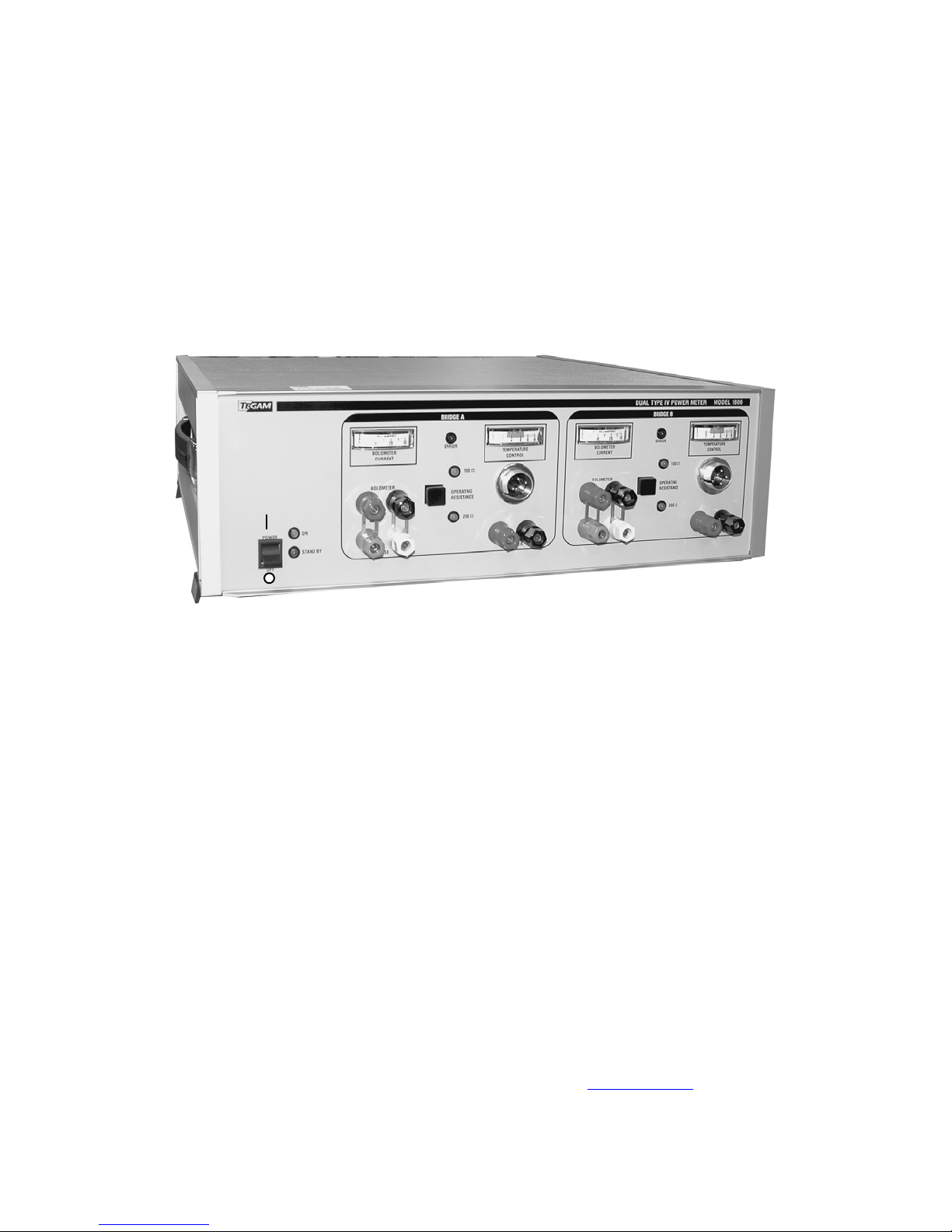
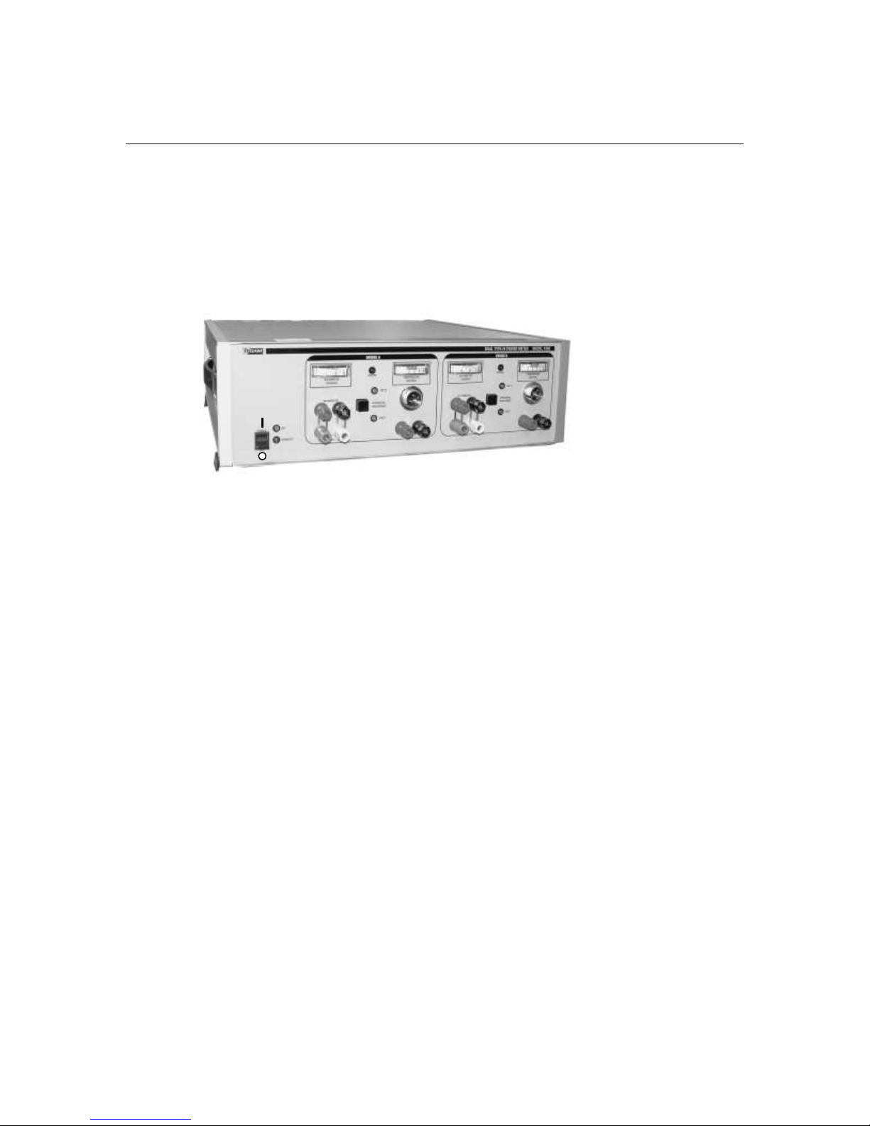
This manual contains operation and maintenance information for the TEGAM Model 1806
Dual Type IV Power Meter shown in Figure 1-1. This information is in five sections that
outline general information, installation, operation, principles of operation and maintenance.
Discussions throughout this manual concerning use of the Model 1806 treat it as a stand-alone
item. The TEGAM System IIA Automatic Power Meter Calibration System manual contains
information for use, operational role, and cabling of the Model 1806 within a power sensor
calibration system.
Figure 1-1 Model 1806 Dual Type IV Power Meter
PURPOSE AND USE OF EQUIPMENT
The TEGAM Model 1806, in conjunction with an external thermistor mount and a digital
voltmeter (DVM), forms a precision power measurement system that measures microwave
power within the frequency bandwidth of the thermistor mount. The primary application of
this system is for power sensor calibration. The Model 1806 contains two Type IV Bridge
circuits and two thermistor mount temperature controllers. Each Type IV Bridge circuit
operates at a dc resistance of either 100 or 200 ohms which is front-panel selectable. A
complete power measurement system includes an accurate DVM and some means of offsetting
the DVM to measure small voltage changes more accurately. This offsetting voltage source or
reference voltage generator (RVG) becomes increasingly important when measuring power
levels below a few milliwatts. The Model 1806 is designed for use with a temperaturestabilized thermistor mount (100 or 200 ohms) and a DVM with a 6.5 digit, or higher,
resolution.
The Model 1806 contains two self-balancing Type IV Bridge circuits that pass current through
a bolometer mount while sensing the voltage across the mount which defines the resistance of
the bolometer at its dc terminals. This process eliminates lead errors associated with
Wheatstone Bridges. Therefore, the Model 1806 suits applications such as power
measurement and insertion loss measurement applications, requiring high accuracy and
computer control.
The role of the Model 1806 within the TEGAM System IIA Automatic Power Meter
Calibration System is to measure precisely RF and microwave power applied to terminating
standards in order to transfer the calibration factor of one standard to another. The System IIA
is an IEEE Bus compatible system designed to calibrate feedthrough and terminating power
sensors in the .01 to 18.0 GHz frequency range.
SPECIFICATIONS
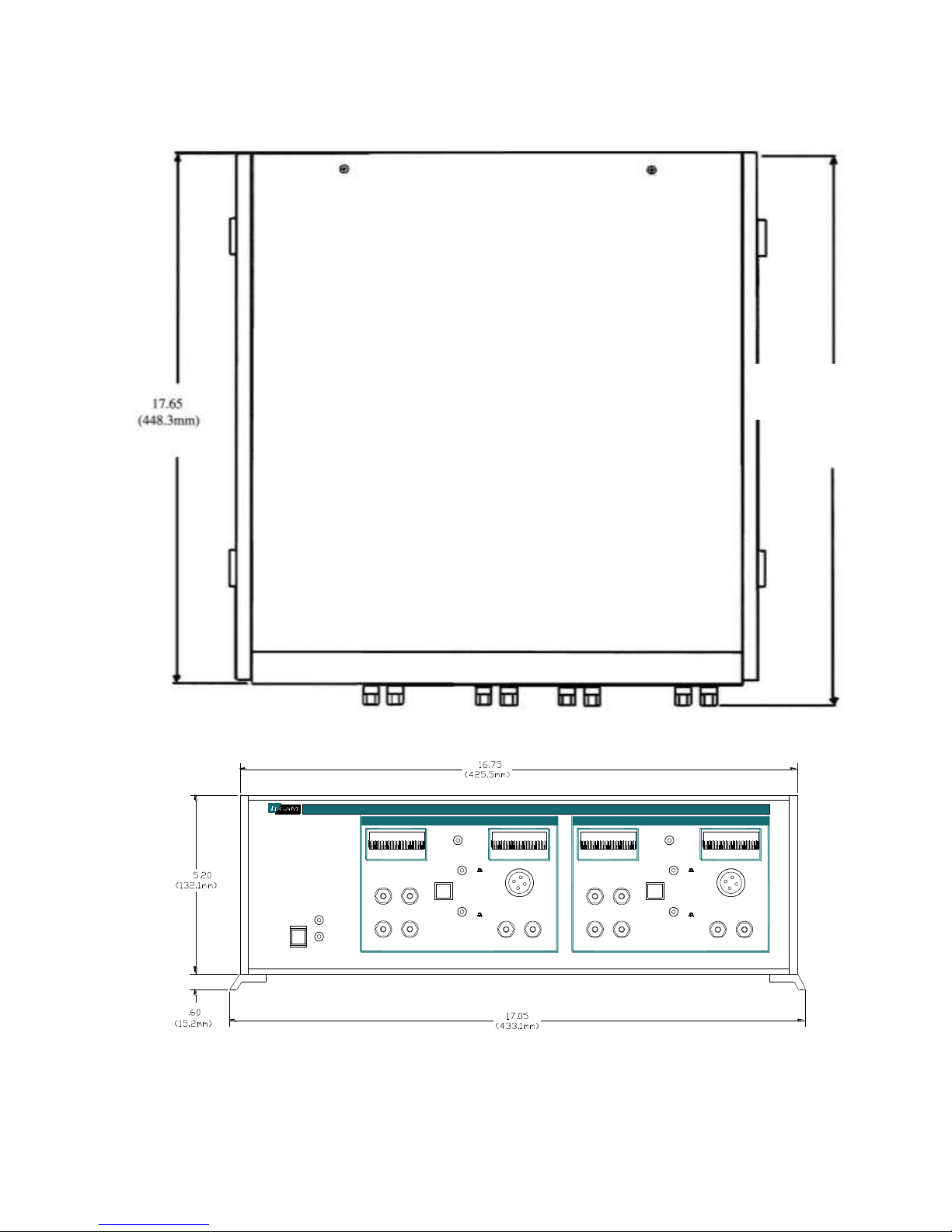
Table 1-1 contains the electrical, physical, and environmental specifications for the
Model 1806. Figure 1-2 contains an outline drawing and design dimensions.
Page 8

Instruction Manual Section I
1-2
RF Power Measurement Range:
10 W to 25 mW
Substitution Bridge Accuracy:
0.003%
Power Measurement Accuracy:
0.03% + 2W when using an HP 3458A Voltmeter
Bias Power Temperature
Sensitivity:
2 W/C/hr
Ambient Temperature Dynamic
Range:
+12C to + 32C
(54°F to 90°F)
Mount Warm-up Time:
2 hrs. to achieve + 60°C (140°F) nominal operating
temperature
Loop Gain:
80 dB minimum
Open Loop Frequency Response:
0.1 Hz
Thermistor Mount Temperature
Control Indicator Operating
Range:
Temperature meter with marked operating point
Bolometer Mount Bias Current
Indicator Resolution:
0.1 mA
Power Requirements:
100/120/220/240 VAC, (+5%, -10%) 25W, 48-62 Hz
Dimensions:
18.35 in. (466.1 mm) L x 17.05 in. (433.1 mm) W x 5.80 in
(147.3 mm) H
Constructions:
Cabinet or standard rack mount
Weight:
Net: 16 lbs. (7.26 kg)
Shipping: 20 lbs. (9.07 kg)
Dual Type IV Power Meter, Model 1806 General Information
Table 1-1 Model 1806 Dual Type IV Power Meter Specifications
ITEMS SUPPLIED
The following items are supplied with the TEGAM Model 1806 Dual Type IV Power Meter:
1. Assembly AC Power Cable, P/N 068-21, 1 ea.
2. Assembly Temperature Control Cable, P/N 138-477, 2 ea.
3. Assembly Mount Bias Cables, P/N 138-526, 2 sets ea.
4. Model 1806 Instruction Manual (IM-140), 1 ea.
5. Shorting Link, P/N 138-495, 4 ea. (installed on front panel)
OPTIONAL ACCESSORIES
The following items can be purchased separately and are needed to perform
calibration service on the 1806.
1. Assembly Extender Board, P/N 138-439, 1 ea.
2. Printed Circuit Card Pullers, P/N 139-1141, 2 ea.
Page 9
Instruction Manual Section I
1-3
18.35
(466.1mm)
CONTROL
TEMPERATURE
ERROR
100
OPERATING
RESISTANCE
200
VOLTMETERSENSE
BOLOMETER
CURRENT
BOLOMETER
O
I
POWER
OFF
ON
STAND BY
VOLTMETER
100
ERROR
CURRENT
BOLOMETER
RESISTANCE
OPERATING
200
BOLOMETER
SENSE
TEMPERATURE
CONTROL
Dual Type IV Power Meter, Model 1806 General Information
Figure 1-2 Model 1806 Dimensions (Top/Front)
Page 10

Instruction Manual Section I
1-4
Dual Type IV Power Meter, Model 1806 General Information
Page 11

Instruction Manual Section II
2-1
Dual Type IV Power Meter, Model 1806 Installation
SECTION II INSTALLATION
UNPACKING AND INSPECTION
TEGAM ships the Model 1806 cushioned between molded-in-place expanded plastic pads in a
double-walled carton. Upon unpacking the equipment, retain the shipping container and
packing material until the equipment has been thoroughly inspected and it is ensured that
reshipment is not necessary. Perform the following initial inspection:
a. Carefully look at the outside of the shipping container for discoloration, stains, charring,
or other signs of exposure to excessive heat, moisture, or liquid chemicals. Check for any
physical damage to the shipping container such as dents, snags, rips, crushed sections or
areas, or similar signs of excessive shock or careless handling.
b. With the equipment and any accessory package removed from the shipping container,
check each item against the packing list or items supplied list. If any items are missing,
contact the factory or the manufacturer’s local representative.
c. Carefully inspect the equipment looking for dents, deep scratches, damaged or loose
pushbuttons or knobs, or any other signs of physical abuse or careless handling.
If damage is found, forward an immediate request to the delivering carrier to perform an
inspection and prepare a concealed damage report. Do NOT destroy any packing material
until it has been examined by an agent of the carrier. Concurrently, report the nature and
extent of damage to TEGAM giving equipment model and serial numbers, so that necessary
action can be taken. Under U.S. Shipping regulations, damage claims must be collected by the
consignee; do NOT return the equipment to TEGAM until a claim for damages has been
established.
PREPARATION FOR RESHIPMENT OR STORAGE
RESHIPMENT
Perform the following procedures when reshipping an instrument or component:
DO NOT return any instrument or component to TEGAM without receiving prior factory
authorization (RMA Number).
Use the best available packing materials to protect the instrument during reshipment.
When possible, use original shipping container and packing materials.
a. Wrap the instrument in sturdy paper or plastic;
b. Place the wrapped instrument in a strong shipping container and place a layer of shock-
absorbing material (3/4 inch minimum thickness) around all sides of the unit to provide a
firm cushion and to prevent movement inside the container;
c. If shipping the unit for service, attach a tag to indicate:
1. Model and serial numbers,
2. Service required,
3. Description of malfunction,
4. Return address,
5. Authorization to conduct repairs; and
Thoroughly seal the shipping container and mark it FRAGILE.
STORAGE
Storage of the unit is possible for extended periods without incurring damage to internal
circuitry if the instrument is packaged according to the instructions above. The safe limits for
storage environment are:
Temperature: -67 to + 167 F (-55 to + 75 C)
Humidity: 95%
Altitude: 40,000’ (12,192M)
Page 12

Instruction Manual Section II
2-2
Dual Type IV Power Meter, Model 1806 Installation
POWER, ENVIRONMENTAL AND MOUNTING REQUIREMENTS
TEGAM supplies a detachable, three-conductor power cord for connecting an ac power
source of 48 to 62 Hz at line voltages of 100, 120, 220, or 240 volts +5%, -10% to the
Model 1806. This ac power source supplies the Model 1806 with all operational power
required. The Model 1806 requires no other external power.
The Model 1806 operates within its specifications at an ambient temperature of +12 C to
+32 C. Operating beyond these limits could affect the accuracy of this unit and damage
internal circuitry.
TEGAM ships the Model 1806 with four plastic feet and a tilt stand mounted on the
bottom of the unit for bench use; however, the Model 1806 is also rack-mountable. To
rack-mount the unit, first remove the four plastic feet and the tilt stand on the bottom of
the unit. Next, remove the rear panel trim and slide the side panels out. Then, remove
the side trim and install rack adapters on the left and right sides of the Model 1806. Reattach the rear panel trim to the unit while leaving the side panels off. When rack
mounting the unit, ensure access to the rear panel so that rear panel connections can be
made. The unit may now be mounted into a standard rack.
INSTALLATION
Installation of the Model 1806 consists of rack mounting or bench configuring the unit,
selecting the proper line-voltage fuse and circuit board, and connecting the unit to the desired
ac power source that matches the fuse and circuit board.
POWER INPUT CONNECTOR AND VOLTAGE SELECTOR/FUSE ASSEMBLY (XF1)
Assembly XF1 is in the lower right-hand corner of the rear panel of the Model 1806. This
assembly contains a three-prong ac power input connector and a voltage selector circuit
board/fuse assembly. The design of XF1 prevents use of the voltage selector/fuse assembly
while an ac power cord is connected to the ac power input connector. Disconnect the power
cord and slide the protective plastic window to the left to change the line fuse and printed
circuit (PC) board. This arrangement eliminates the possibility of electric shock to operating
personnel.
Power source voltages of sufficient current to constitute a HAZARD to operating
personnel exist at the voltage selection PC board and line fuse. Ensure that the power
cord is DISCONNECTED prior to changing line voltage selection or line fuse.
AC Power Input Connector
This connector, located on the left side of XF1, is a plug-type, prong-insert connector with
three conductors for connection of the 100/120/200/240 volt ac power cord (P/N 068-21) to the
power supply assembly within the Model 1806. Arrangement of the conductors and keying of
the insertion area prevent an incorrect connection. This connector also passes the ground
current of the Model 1806 when the ac power cord is plugged into a grounded wall outlet.
When the wall outlet contains two insertion slots, use a three-prong-to-two-prong adaptor.
Voltage Selector/Fuse Subassembly
The voltage selector/fuse subassembly on the right side of XF1 reconfigures the Model 1806
for different operational voltages. This subassembly contains a line fuse and a voltage selector
PC board. Replacement of the fuse and proper selection of the voltage selector PC board
change the operational power requirement to ac voltages of either 100, 120, 220, or 240 volts
at 48 to 62 Hz. Refer to the following paragraph for the proper fuse/PC board selection.
Selection of Proper Fuse/Circuit Board for XF1
TEGAM ships the Model 1806 configured for 120-volt operation. Table 2-1 lists fuse
requirements for other available operational voltages. Figure 2-2 depicts the procedure,
including outline steps, for removal of the line voltage fuse, selection of the proper line-voltage
PC board, and replacement of the fuse.
Page 13

Instruction Manual Section II
2-3
Operational Line Voltage
Fuse Requirement
100 volts +5%, -10% at 48 to 62 Hz
0.75 Amp Slo-Blo
120 volts +5%, -10% at 48 to 62 Hz
0.75 Amp Slo-Blo
220 volts +5%, -10% at 48 to 62 Hz
0.4 Amp Slo-Blo
240 volts +5%, -10% at 48 to 62 Hz
0.4 Amp Slo-Blo
Dual Type IV Power Meter, Model 1806 Installation
Page 14

2-4
Figure 2-1 Model 1806 Dual Type IV Power Meter Rear Panel Voltage Selector/Fuse Assembly
FLOAT/GROUND
Switch (S3)
Power Input
Connector and
Voltage
Selector/Fuse
Assembly (XF1)
Instruction Manual Section II
Dual Type IV Power Meter, Model 1806 Installation
Page 15

Instruction Manual Section II
2-5
VOLTAGE SELECTION PROCESS
STEP PROCESS
1. Pull to the back and left on the fuse pull lever to eject the fuse.
2. Remove the voltage selector circuit board from the module by pulling it out carefully.
3. Position the voltage selector circuit board so that the desired voltage appears readable
(right-side-up) on the left-hand side of the wafer as it faces you. The “X” on the board in
the diagram depicts this location.
4. Slide the board back into the module as shown in the diagram with the desired voltage
still appearing as set in step 3.
5. Replace the fuse with the proper fuse according to Table 2-1. Re-insert the new fuse by
placing it in the fuse brackets.
Figure 2-2 Model 1806 Operational Voltage Selection Process
Dual Type IV Power Meter, Model 1806 Installation
Page 16

Instruction Manual Section III
Dual Type IV Power Meter, Model 1806 Operation
SECTION III OPERATION
GENERAL OPERATING CONSIDERATIONS
Operation of the Model 1806 consists of: (1) cabling the unit to the device for testing, (2)
selecting the proper voltage fuse and circuit board, (3) grounding or ungrounding the Model
1806, (4) selecting the proper operating resistance, (5) monitoring several indicators and
meters located on the front panel of the unit, (6) using a digital voltmeter (DVM) or a DVM
and a reference voltage generator (RVG) to measure substituted dc bias, and (7) calculating the
amount of RF power. The Model 1806 contains two identical Type IV Bridge circuits (Bridge
A and Bridge B) with individual sets of controls and indicators. Two black outlined squares
on the front panel separate each set of controls and indicators for each bridge. Figure 3-1
depicts these bridge control panels. Since both bridge circuits perform identical functions,
Section III discusses operation of Bridge A only. Operation of Bridge B is exactly the same as
Bridge A operation. Operation of these bridges may occur individually or simultaneously.
Figure 3-1 also shows the front panel location of meters, indicators, switches and connectors
that control the operations of the Model 1806. Refer to this figure throughout the discussion in
Section III.
The TEGAM System II Automatic Power Meter Calibration System manual contains
information about typical power meter calibration procedures.
FRONT PANEL METERS, INDICATORS, SWITCHES & CONNECTORS
The Model 1806 contains a Power Switch that controls power for the entire unit. Two
indicators located next to the switch show the Model 1806 power status. As shown in Figure
3-1, each bridge control panel contains two meters, three dual binding post connectors, one
temperature control connector, three light-emitting diode (LED) indicators, and an operating
resistance switch.
FRONT PANEL CONNECTORS
The front panel of the Model 1806 contains fourteen connectors, seven connectors for each
bridge. The following paragraphs discuss connectors contained in Bridge A only. Bridge B
connectors have functions identical to those in Bridge A. Refer to Figure 3-1 for locations of
all connectors.
Bolometer Mount Bias Connectors (TP3 and TP4)
Bolometer Mount Bias Connectors TP3 and TP4 are spade-lug connecting posts that pass dc
current applied by the Model 1806 to and from a thermistor mount (typically Model 1110).
The location of TP3 and TP4 is in the lower left-hand corner of Bridge A above the Mount
SENSE Lead Connectors. The red connector is for positive dc bias current and the black
connector is for dc bias current return.
Mount SENSE Lead Connectors (TP1 and TP2)
Mount SENSE Lead Connectors TP1 and TP2 are spade-lug type connecting posts located in
the lower left-hand corner of Bridge A. Voltage present at TP1 and TP2 is proportional to the
effective dc current passing through the thermistor element. Use of the voltage potential
present at TP1 and TP2 reduces errors associated with lead resistance.
Temperature Control Connector (J5)
The location of TEMPERATURE CONTROL Connector J5 is in the center-right of Bridge A.
This connector is a four-pin threaded connector that links a temperature controller within the
Model 1806 to a heater which stabilizes the internal temperature of the thermistor mount. The
TEMPERATURE CONTROL Meter M2 indicates current present at this connector.
3-1
Page 17

Instruction Manual Section III
Figure 3-1 Model 1806 Dual Type IV Power Meter Front Panel Meters, Indicators, Switches, and Connectors
Dual Type IV Power Meter, Model 1806 Operation
3-2
Page 18

Instruction Manual Section III
Dual Type IV Power Meter, Model 1806 Operation
Voltmeter Connectors (TP5 and TP6)
VOLTMETER Connectors TP5 and TP6 are spade-lug connecting posts. Placement of these
connectors is in the lower right-hand corner of either bridge (shown in Figure 3-1 on Bridge
B). TP5 and TP6 complete the dc path between the Model 1806 and a digital voltmeter with a
6.5-digit resolution. DC voltage present at TP5 and TP6 is equivalent to the voltage across the
thermistor element. The red connector is for positive (+) dc power and the black connector is
for negative (-) dc power.
FRONT PANEL METERS
The front panel of the Model 1806 has four analog meters, two for each bridge. They are the
TEMPERATURE CONTROL Meter and the BOLOMETER CURRENT Meter. The
following discussion of Bridge A meters applies equally to Bridge B meters. Figure 3-1 shows
the location of front panel meters.
Bolometer Current Meter (M1)
The Bolometer Current Meter M1 is in the upper left-hand corner of Bridge A. M1 measures,
with a resolution of .1 mA, the thermistor bias current level applied through the Model 1806
Bolometer Mount Bias Connectors.
Temperature Control Meter (M2)
Temperature Control Meter M2 is in the upper-right-hand corner of Bridge A. M2 indicates a
dc voltage level that is proportional to the current applied through Temperature Control
Connector J5 to a heater bridge in the thermistor mount. The green area on M2 indicates that
the thermistor mount is in the correct temperature range.
FRONT PANEL INDICATORS
The Model 1806 contains eight front-panel LED indicators. Each bridge control on the Model
1806 contains three indicators and the overall unit control contains two indicators. This
assortment of LEDs varies in color from yellow to green to red. Each indicates either an ON
or OFF condition. Figure 3-1 also shows the location of front panel indicators.
ON Indicator (DS1)
The location of DS1 is in the lower left-hand corner just to the right of the POWER Switch S1.
This green indicator illuminates when the Model 1806 POWER Switch is in the ON position
indicating supply of operational power to the unit and availability of all operations.
Standby Indicator (DS2)
The DS2 indicator location is just below indicator DS1 in the lower left-hand corner of the
front panel. This yellow indicator illuminates when the Model 1806 POWER Switch is in the
STANDBY position and power is being applied to the unit. Illumination of DS2 indicates that
partial power is supplied to the unit and test functions such as changing the bridge operating
resistance or monitoring bridge bias are not available.
100 Ohm Operational Indicator (DS4)
Each bridge circuit on the Model 1806 contains indicator DS4 in the center of the bridge
control panel (shown in Figure 3-1 on Bridge B). This green indicator illuminates when the
OPERATING RESISTANCE Switch S2 sets the bridge circuitry for 100 Ohm operation.
200 Ohm Operational Indicator (DS5)
Each bridge circuit on the Model 1806 also contains indicator DS5 below DS4 on the front
panel (shown in Figure 3-1 on Bridge B). This green indicator illuminates when the
OPERATING RESISTANCE Switch S2 sets the bridge circuitry for 200 Ohm operation.
3-3
Page 19

Instruction Manual Section III
Dual Type IV Power Meter, Model 1806 Operation
Error Indicator (DS3)
Each bridge on the Model 1806 contains one red DS3 indicator between meters M1 and M2 at
the top of the bridge control panel. ERROR indicator DS3 illuminates for any condition
preventing the Type IV Bridge circuit from balancing.
MODEL 1806 SWITCHES
The Model 1806 uses two front panel switches and one rear panel switch during individual
bridge operation. Switch S1, located on the front panel, selects ON/OFF/STANDBY power
requirements for the entire Model 1806. Each bridge control panel on the Model 1806
employs one switch S2 for selecting the bridge circuit operating resistance. Figure 3-1 depicts
the location of front panel switches. The rear panel of the Model 1806 contains one switch S3
for grounding or ungrounding the Model 1806 depending on the ground state of the thermistor
and DVM used with the Model 1806.
Power Switch (S1)
The Model 1806 POWER Switch S1 controls operational power. S1 is in the lower left-hand
corner of the front panel next to the ON Indicator DS1. S1 is a three-position toggle switch
that completes, extends, or terminates power to the Model 1806. In the uppermost position, S1
extends power to the entire circuitry within the Model 1806 that enables all unit operations. In
the middle position, S1 places the Model 1806 in a STANDBY mode for warm-up.
STANDBY mode applies only necessary power to heat the Model 1806 and associated
thermistor mounts. When switched to the lowest position, S1 terminates power to the Model
1806.
Ensure that input connector and voltage selector/fuse assembly are set for the proper voltage
before switching the POWER Switch (S1) to ON or STANDBY; otherwise, damage may
result to internal circuitry.
100/200 Ohm Operating Resistance Switch (S2)
Each bridge on the Model 1806 contains a two-position, push-button OPERATING
RESISTANCE Switch S2. The location of this switch is in the center of each bridge control
panel. The position of S2 configures individual bridge circuitry for either 100- or 200-ohm
operation. Depending on the position of this switch, either the 100 ohm or 200 ohm
operational indicator will be illuminated. When using a 100 ohm thermistor mount, set S2 to
the in position for 100 ohm operation and to illuminate operational indicator DS4. When using
a 200 ohm thermistor mount, set S2 to the out position for 200 ohm operation and to illuminate
operational indicator DS5.
Float/Ground Switch (S3)
FLOAT/GROUND Switch S3 is a two-position, toggle switch located on the rear panel
directly above the Power Input Connector and Voltage Selector/Fuse Assembly XF1 (refer to
Figure 2-1). S3 grounds or ungrounds (floats) the Model 1806 depending on whether or not
the thermistor and DVM are grounded. The up position of S3 grounds the Model 1806. The
down position of S3 floats the Model 1806. If either the thermistor mount or DVM or both are
grounded, place the FLOAT/GROUND Switch in the FLOAT position. When both bridges
are used, if any external voltage measuring instrument is grounded, place the
FLOAT/GROUND Switch in the FLOAT position.
RF POWER LEVEL MEASUREMENT
The Model 1806 is one component in a precision measurement system that measures RF power
in terms of a dc voltage change across the Model 1806 bridge circuit. This system measures
the voltage change with a digital voltmeter (DVM) with a 6.5 digit resolution – or the same
DVM and reference voltage generator (RVG) when the applied RF power level is small (a few
milliwatts). The following paragraphs describe these two methods of measurement.
3-4
Page 20

Instruction Manual Section III
[(V1)
2
- (V
2
)2]
R0
Pdc
K1
Dual Type IV Power Meter, Model 1806 Operation
RF POWER MEASUREMENT WITH DVM ONLY
The Precision Measurement System does not measure the RF power level directly. Instead, a
DVM measures dc voltages before and after the application of RF power to the Model 1806
bridge. This necessitates calculation of the RF power level using data obtained from the DVM
measurements.
To calculate the RF power level applied to the thermistor element, configure the Model 1806
and the DVM according to Figure 3-2 and measure the voltage across the bridge with the
DVM before the application of RF power, V1. Then measure the voltage across the bridge
after applying RF power and record that measurement as V2. Determine the RF power level
using the following equations:
First, calculate the level of proportional dc substituted power from the operating resistance and
DVM readings with the equation:
Pdc =
Where:
V
V
R
P
Next, calculate the applied RF power level using the mount calibration factor and the level of
dc substituted power:
PRF =
Where:
P
P
K
1
2
0
dc
RF
dc
1
= DVM reading across the bridge in the absence of RF power,
= DVM reading across the bridge with RF power applied, and
= Mount operating resistance (100 or 200 ohms)
= dc substituted power which is proportional to the applied RF power
= Level of RF power applied to the terminating thermistor,
= Level of proportional dc substituted power from previous equation, and
= Terminating Mount calibration factor directly traceable to NIST
___________________
_________
Figure 3-2 Location of Digital Voltmeter in Typical Test Configuration
RF POWER LEVEL MEASUREMENT WITH DVM AND
REFERENCE VOLTAGE GENERATOR
When the applied RF power level becomes small, change of voltage across the bridge also
becomes very small. In this situation, even a high-accuracy voltmeter magnifies measurement
3-5
Page 21

Instruction Manual Section III
(2V
1
– V
D
2
+ V
D
1
) x (V
D
2
– V
D
1
)
R0
Dual Type IV Power Meter, Model 1806 Operation
uncertainties because the large DVM measurement scale has limited resolution. Use of a
reference voltage generator, like the one in Figure 3-3, minimizes voltmeter uncertainties by
enabling use of a measurement scale that has better resolution.
When a reference voltage generator is used with the DVM, calculation of the RF power level
requires a different process. First, adjust the reference voltage generator to an output power
level approximately equal to the Model 1806 bridge output measured by a DVM when no RF
power is applied. Ensure stabilization of the RVG output throughout the entire measurement
period. Next, record the DVM reading with no RF power applied to the bridge and the doublepole, double-throw switch in the “Measure V
” position. This value is (V
1
). Switch the DVM
1
to a scale with improved resolution for smaller power levels. Record the DVM reading with
no RF power applied and the double-pole, double-throw switch in the “Measure V
” position.
D
This reading is the difference between the Model 1806 bridge output and the setting of the
reference voltage source (VD1). Finally, apply RF power to the bridge and record the
voltmeter reading with the double-pole, double-throw switch in the “Measure V
” position.
D
This value is the difference between the Model 1806 output and RVG output including the
proportional RF power effect on the bridge circuit (VD2). Use these values and the following
method to calculate the applied level of RF power.
First, determine the level of dc substituted power using the measurements taken above with the
equation:
Pdc =
______________________________
Where:
V
V
R
P
V
dc
= Model 1806 bridge output measured by DVM with no RF power applied,
1
= Difference between 1806 bridge output with no RF applied and RVG output,
D1
= Difference between 1806 bridge output with RF applied and RVG output
D
2
= Mount operating resistance, and
0
= Proportional amount of dc substituted power.
Next, apply the mount calibration factor to find the level of RF power using the second
equation in the “RF POWER MEASUREMENT WITH DVM ONLY” section above.
Figure 3-3 Location of Reference Voltage Generator in Typical Test Configuration
3-6
Page 22

Instruction Manual Section IV
4-1
Pdc
K1
PRF
Pdc
Dual Type IV Power Meter, Model 1806 Principles of Operation
SECTION IV PRINCIPLES OF OPERATION
INTRODUCTION
This section contains information that describes the basic circuitry and functions of the Model
1806 Dual Type IV Power Meter - the major component in a precision power measurement
system that measures high-frequency or microwave power in the .01 to 18 GHz range. The key
role of the Model 1806 within this system is the realization of the principle of dc substitution.
It also provides temperature stabilization of up to two mounts each associated with one of the
two bridges.
The Model 1806 contains a power supply assembly and five printed circuit (PC) boards. The
five PC boards are the temperature control board, two bridge boards, a front panel board, and a
motherboard. The functions of each of these boards are detailed in this section.
PRINCIPLE OF DC SUBSTITUTION
The Model 1806 uses the principle of dc substitution to provide a measure of RF power. DC
substitution refers to the measurement of RF power according to the amount of dc power that
must be substituted for the RF power in a bolometer in order to cause equivalent thermal
effects. This principle extends to the determination of terminating thermistor mount calibration
factors (ratio of substituted dc power to the power incident on the thermistor mount) by the
following formulas:
PRF =
K1 =
Where:
PRF = the RF power incident on the terminating mount.
Pdc = the dc substituted power as measured at the Model 1806.
K1 = the measured or known calibration factor for the terminating mount.
RF power measurements are traceable to a primary laboratory standard in cases where the
terminating thermistor mount has been calibrated by NIST.
_______
_______
PRECISION POWER MEASUREMENT SYSTEM
The Model 1806 Dual Type IV Power Meter, the NIST-calibrated TEGAM Model 1110
Terminating Mount, a reference voltage generator, and a digital voltmeter with a 6.5 digit
resolution combine to provide the precision power measurement system shown in the
functional block diagram in Figure 4-1. This system features one of the two Model 1806
closed-loop, self-balancing Type IV Bridge circuits consisting of two legs--a precision
resistance leg (100 or 200 ohms) and a leg linked to a thermistor element in the Model 1110. A
thermistor is a type of bolometer whose resistance decreases as a function of increasing heat
associated with ambient temperature or applied power.
This system also features the Model 1806 temperature control circuitry that temperature
stabilizes the thermistor mount. This eliminates changes in the thermistor element's resistance
due to ambient temperature changes and thus isolates the causes of thermistor variation to the
application of RF and dc power only.
An IEEE - 488 bus-compatible controller controls DVM measurements across the precision
resistance leg of the Model 1806 bridge circuit. A reference voltage generator (RVG) increases
the accuracy of the DVM measurements when the RF power level is below a few milliwatts.
Page 23

Instruction Manual Section IV
4-2
Dual Type IV Power Meter, Model 1806 Principles of Operation
Figure 4-1 Functional Block Diagram of Precision Power Measurement System
SELF-BALANCING BRIDGE CIRCUITS
The Model 1806 contains two identical bridge circuits on individual PC boards that perform dc
substitution independently from each other. Figure 4-2 shows a simplified schematic of one of
the two bridge boards circuits depicting its interaction with system components internal and
external to the Model 1806.
Each self-balancing bridge circuit, in a closed-loop configuration, consists of two legs: a
precision resistance leg (l00-ohm or 200-ohm) and a leg containing a thermistor element. The
precision resistance leg maintains a constant effective resistance value of either 100 or 200
ohms depending on the bridge operating resistance selection. When the thermistor mount is
temperature stabilized by the Model 1806 temperature controller, thermistor resistance varies
solely due to the application of RF and dc power.
Each leg uses an operational amplifier (U1 or U2) to sense voltage imbalances and to drive
transistors (Q1 and Q2) to correct them. The power supply assembly provides isolated 15 volt
biasing to each op-amp. Since the voltage differential at the input stage of op amp U2 is
negligibly small, it provides a virtual common reference to op amp U1 (i.e., it acts as a virtual
common ground since the voltage approaches zero with respect to either ground). This forces
the current through the thermistor to equal the current through the precision resistance leg.
The application of RF power to the thermistor element creates a decrease in the voltage drop
across the thermistor element due to its negative temperature coefficient. This decreased
voltage drop in turn creates an unbalanced bridge condition. When resistance in the thermistor
element leg of the bridge changes due to the application of RF power, op amp U1 senses a
voltage difference between Va and Va' and causes Va' to equal Va. When Va' equals Va, the
voltage across the thermistor element leg equals the voltage across the precision resistance leg.
Also, the closed loop circuit configuration maintains equal current throughout the bridge. Since
the voltage and current throughout the circuit is equal, the resistance in both halves is also
equal. Therefore, when the thermistor mount's temperature is stabilized and RF power is
applied, a change in voltage across the precision resistance leg is proportional to the amount of
RF power applied to the themistor mount.
Page 24

Instruction Manual Section IV
4-3
V2
R
Dual Type IV Power Meter, Model 1806 Principles of Operation
Figure 4-2 Simplified Schematic of Precision Power Measurement System
POWER MEASUREMENTS
The precision measurement system measures RF power in terms of a voltage change across the
precision resistance leg. The digital voltmeter measures voltage across the precision resistance
leg before the application of RF power (V1) and after the application of RF power (V2). The
difference, V2 – V1, indicates the change in voltage across the precision resistance leg due to
the application of RF power. The RF power introduced to the thermistor is directly
proportional to the change in dc power across the precision resistor. The change in dc power is
calculated by the formula:
Pdc =
Where:
Pdc = the change in dc power across the precision resistor
V2 = change in voltage across the precision resistor (V
R = resistance value of precision resistor
______
2
2
– V
1
)
2
Page 25

Instruction Manual Section IV
4-4
[(V
1
)
2
- (V
2
)
2
]
R0
K1
Pdc
Dual Type IV Power Meter, Model 1806 Principles of Operation
RF Power Level Calculation
The Model 1806 measures high-frequency or microwave power in terms of a dc voltage
change. The system does not measure the RF power level directly. Instead, it measures dc
voltages before and after the application of RF power using a DVM or a DVM and an RVG.
The difference between these voltages is proportional to the RF effect on the thermistor's
resistance and is calculated in terms of dc substituted bias required to rebalance the bridge as
follows:
Pdc =
Where:
V1 = DVM reading across the precision resistance leg in the absence of RF power,
V2 = DVM reading across the precision resistance leg with RF power applied,
R0 = Mount operating resistance (100 or 200 ohms), and
P
power
The dc effect is translated into an RF power level using the mount calibration factor according
to this equation:
P
Where:
P
P
K
= DC power across precision resistance which is proportional to the applied RF
dc
= Level of RF power applied to the thermistor,
RF
= Level of proportional dc substituted power from previous equation, and
dc
= Terminating Mount calibration factor which is directly traceable to NIST.
1
_______________
_____
=
RF
CONTROLLING THERMISTOR MOUNT INTERNAL TEMPERATURE
When the Model 1806 operates in conjunction with a thermistor mount, a temperature sensitive
device, it must eliminate or minimize the effects of changes in the ambient temperature upon
the thermistor in order to provide precise measurements. The Model 1806 temperature control
board accomplishes this by raising the mount's internal temperature to a level higher than the
ambient temperature and maintaining that level by controlling the current applied to the
mount's internal heater element. This prevents any thermistor imbalance due to ambient
temperature change. Therefore, all temperature changes are due to the application of RF and dc
power. The temperature controller maintains the temperature of one or two external
temperature-stabilized thermistor mounts above the ambient temperature.
Figure 4-3 Simplified Schematic of Model 1806 Temperature Control Board
Page 26

Instruction Manual Section IV
4-5
Dual Type IV Power Meter, Model 1806 Principles of Operation
TEMPERATURE CONTROL BOARD
The temperature control board performs three basic functions: the control of current applied to
the mount heater, indication of the mount temperature by a front panel meter, and illumination
of a balanced-state indicator LED on the temperature control board (window indicator) Refer
to Figure 4-3 for the following discussions concerning the temperature control circuit The
temperature control board controls current to the thermistor mount heater element which is a
thermal bridge configuration. U1, a high-gain amplifier with excellent offset drift
characteristics, senses imbalances across the thermal bridge located in the temperaturestabilized feedthrough thermistor mount via inputs 2 and 3. This thermal bridge, which is
composed of two types of resistance with differing temperature coefficients, balances at
approximately 60C. U1/U2 interaction provides a varying response to thermal bridge
imbalances according to the relationship between the voltage differential inputs. U1/U2
amplifies an imbalance signal from a cold thermal bridge that forces the series pass transistor
Q3 to pass a current proportional to the imbalance signal. This current drives the mount heater
to restore thermal bridge balance. As the thermal bridge nears the steady-state condition, Q3
causes DS1 to illuminate. If the mount is cold, DS1 does not illuminate since the Darlington
pair configuration made up by U2-2 and Q4 is not in a conducting state. U1/U2 responds to an
imbalance signal from an overheated mount by turning off Q3 so that it passes no current to
the heater or DS1.
Transistor Q2 and Resistor R16 combine to provide circuit protection by limiting current in the
event of an output short circuit.
Throughout this process, the TEMPERATURE CONTROL Meter M2 senses the balance state
of the thermistor heater element. This control meter contains a marked green operating range
that indicates the operating point for thermistor mount temperature stabilization.
MODEL 1806 POWER SUPPLY
The power supply assembly transforms the ac power input into six different power sources for
the varying operations of the Model 1806 while completely isolating those supplies for bridge
circuitry biasing. These power supplies consist of + 5-volt and + 20-volt operational power
supplies and four completely isolated + 15-volt bridge board biasing power supplies. The + 5volt control signal enables front panel controls and is applied only when the Model 1806 is in
the ON mode. The + 20-volt potential powers the temperature control circuitry in both
STANDBY and ON modes. The four isolated + 15-volt supplies bias bridge board circuitry in
the STANDBY and ON modes of operation.
POWER SUPPLY ELECTRICAL CONFIGURATION
The power supply electrical configuration uses transformers and a network of full-wave
rectifiers, capacitive filters, and three-terminal voltage regulators to produce the six power
sources needed for Model 1806 operation.
POWER SUPPLY APPLICATION, TRANSFORMATION, & ISOLATION
To produce the six required voltages, the power supply assembly contains two transformers.
One transformer contains dual secondary windings that supply the voltages for the + 5-volt and
+20-volt supplies. The other transformer has four center-tapped secondaries that supply four
15-volt bridge biasing supplies. The power supply assembly isolates the four 15-volt circuits
by using a transformer with primary-to-secondary and secondary-to-secondary isolation. The
power supply circuitry applies these voltages to a network of full-wave rectifiers and
capacitive filters in order to smooth out ripple effects. A series of three-terminal regulators
control the 15volt supplies while two individual variable regulators control the +5-volt and +
20-volt supplies.
When in the STANDBY position, the front panel Power Switch turns off the + 5-volt supply,
thus, disabling front panel switches. When in the ON position, the front panel Power Switch
allows power to all front panel switches.
Page 27

Instruction Manual Section IV
4-6
Dual Type IV Power Meter, Model 1806 Principles of Operation
MOTHERBOARD
The motherboard within the Model 1806 routes power between the power supply assembly and
temperature control board, the bridge board, and the front panel board. The motherboard
contains only simple conductor paths.
FRONT PANEL PC BOARD
The front panel PC board extends the circuitry of the temperature control board, the power
supply assembly, the bridge boards, and the mother board to front panel meters, indicators, and
switches. The front panel PC board contains several electrical components.
MEASUREMENTS USING A REFERENCE VOLTAGE SOURCE
When the applied RF power level becomes small, the change in voltage across the precision
resistance also becomes very small. In this situation, even a high-accuracy digital voltmeter
magnifies measurement uncertainties because the measured voltages differ only slightly and
the DVM has a limited resolution. Use of a reference voltage source, like the one in Figure 4-4,
minimizes voltmeter uncertainties by employing a measurement scale with improved
resolution.
Figure 4-4 Use of Reference Voltage Generator in Typical Test Configuration
The RVG increases measurement accuracy by reducing the voltage output across the precision
resistance by a known amount so that the measurement can be made on a scale with better
resolution. This change takes place because the RVG output and the Model 1806 output are in
opposition when measuring with the double-pole, double-throw switch in the “Measure V
position (refer to Figure 4-4). For example, when the RVG switch is in the “Measure V
position, the connection poles between the DVM and the Model 1806 are aligned and a direct
bridge output reading by the DVM occurs. When the double-pole, double-throw switch is in
the "Measure VD" position, the connection is re-aligned so that the RVG output voltage
opposes the Model 1806 output voltage. This allows only the voltage difference caused by the
introduction of RF power to the Model 1806 bridge to remain. The small reduction of bridge
outputs with and without the application of RF power by the opposition of the reference
voltage generator enables DVM readings on a smaller scale with a wider resolution. This
provides readings of greater accuracy. Since the output difference between the RVG and
Model 1806 with no RF power applied is known (V
difference between the two devices when RF power is applied (V
RF-generated voltage difference (V), which is used to calculate Pdc in the following
equations:
”
D
”
1
), it can be subtracted from the
D
1
). This process leaves the
D
2
Page 28

Instruction Manual Section IV
4-7
1
(2V
1
– V
D
2
+ V
D
1
) x (V
D
2
-V
D
1
)
R0
Dual Type IV Power Meter, Model 1806 Principles of Operation
V
2
= (2V
– V
1
D
+ V
2
D
) x (V
1
-V
D
)
D
2
1
Pdc =
Where:
V = Change in voltage across the precision resistance leg of the Model 1806
bridge,
V1 = Model 1806 bridge output reading with no RF power applied,
V
V
= Difference between Model 1806 output with no RF power applied and
D
1
reference voltage generator,
= Difference between Model 1806 output with RF power applied and reference
D
2
voltage generator,
R0 = Mount operating resistance, and
P
dc
= Proportional amount of dc substituted power
_______________________________
PRECISION MEASUREMENT SYSTEM ERRORS
Precision measurement system errors are due largely to the inaccuracy of the external voltagemeasuring equipment. However, servo errors dependent on power level such as those caused
by amplifier offset and finite gain, amplifier input bias currents, and the nominal resistance of
the precision resistor do occur. Figure 4-5 depicts typical bridge errors over a 30 mW RF
power range with and without a reference voltage generator. Figure 4-5 shows values obtained
when using a typical coaxial dual-element thermistor with an ohms-per-watt coefficient of
1300 and a bias current of 12.8 mA. Because this type of mount experiences a dual-element
substitution error, the normal maximum RF power level is 10 mW. However, the graph in
Figure 4-5 extends beyond this level to illustrate better the nature of errors.
Table 4-1 offers a comparison of voltmeter errors when a reference voltage source is used and
not used over a 0.1-to-10 mW power range.
Figure 4-5 Graph of Typical Bridge Errors With and Without Reference Voltage Generator1
Neil T. Larsen, A New Self-Balancing DC-Substitution RF Power Meter, IEEE TRANSACTIONS ON INSTRUMENTATION
AND MEASUREMENT, VOL. IM-25 NO.4, December 1976, page 345.
Page 29

Instruction Manual Section IV
4-8
Power in
mW
V1 Range
V2 Range
Percent Error With
RVG Use
Percent Error
Without RVG Use
0.100
10.0000
10.0000
0.1552*
23.1772
0.200
10.0000
10.0000
0.0914*
11.5746
0.300
10.0000
10.0000
0.0702*
7.7071
0.400
10.0000
10.0000
0.0595*
5.7734
0.500
10.0000
10.0000
0.0532*
4.6131
0.600
10.0000
10.0000
0.0489*
3.8396
0.700
10.0000
10.0000
0.0459*
3.2871
0.800
10.0000
10.0000
0.0436*
2.8727
0.900
10.0000
10.0000
0.0419*
2.5504
1.000
10.0000
10.0000
0.0405*
2.2926
2.000
10.0000
10.0000
0.0341*
1.1323
3.000
10.0000
10.0000
0.0442**
0.7455
4.000
10.0000
10.0000
0.0400**
0.5520
5.000
10.0000
10.0000
0.0376**
0.4359
6.000
10.0000
10.0000
0.0359**
0.3585
7.000
10.0000
10.0000
0.0348**
0.3032
8.000
10.0000
10.0000
0.0339**
0.2617
9.000
10.0000
10.0000
0.0333**
0.2294
10.000
10.0000
10.0000
0.0328**
0.2035
V
OFF
2
200
Dual Type IV Power Meter, Model 1806 Principles of Operation
Table 4-1 Comparison of Voltmeter Errors When Reference Voltage Generator Is and Is Not Used
*VD Range = .1000V
**VD Range = 1V
CALCULATING MODEL 1806 ACCURACIES
The specification for the Model 1806 Dual Type IV Bridge is given as: Substituted DC Power
Accuracy: 0.03 2% W.
The actual Model 1806 bridge is accurate to better than 0.003 up to 25mW. This means that
the voltages measured across the 200 Ohm resistor in the self-balancing bridge give the bias
power in the thermistor mount to better than 0.003%. Accuracy is lost when the
specifications of the voltmeter used to measure this voltage are taken into account.
For example, consider the Fluke Model 8506A digital voltmeter. It has a 6-1/2 digit display
with quoted specifications after 90 days of 0.001% 8 counts in the 10 Volt range.
Consider the bias of the thermistor beads with no RF power present.
0.030 =
Where V
V
is the voltage across the 200 Ohm resistor.
OFF
OFF
_______
= 2.44949 V
Page 30

Instruction Manual Section IV
4-9
Dual Type IV Power Meter, Model 1806 Principles of Operation
If the incident RF causes the bias to drop by 1 mW, i.e., the dc Substitution power is 1 mW,
then:
V1 = 2.40832V
The 0.001% figure in the voltmeter accuracy, and the 0.003% for the 1806 are linear, and
always in the same direction. The ability to correctly measure the 1 mW is thus directly
affected by both. The 8 counts part of the accuracy can be of any sign or value within these
limits, and is a function of the nonlinearity of the voltmeter.
Thus, in the worst case, the V
could be read as 2.44957 V, i.e., 2.44949+0.00008 and V1 as
OFF
2.40824 V., i.e., 2.40832-0.00008.
The former gives an initial bias power of 30.002 mW and the latter a bias power after RF
substitution of 28.998 mW. The measurement answer would thus be 1.004 mW, i.e., a 0.4%
error. A similar calculation for a 10 mW substituted power gives 0.04% from this alone. This
error is far greater than either the voltmeter reference accuracy or the 1806 bridge accuracy.
Page 31

Instruction Manual Section IV
4-10
Dual Type IV Power Meter, Model 1806 Principles of Operation
Page 32

Instruction Manual Section V
5-1
EQUIPMENT
EQUIPMENT
SPECIFICATlONS
Voltmeter (DC Null Detector)
Range:
Sensitivity of Smallest Scale:
Input Impedance:
Accuracy:
30V
10%V
100 K or greater (resistive)
2% of full scale
General purpose oscilloscope
Bandwidth
10 MHz
Dual Type IV Power Meter, Model 1806 Maintenance
SECTION V MAINTENANCE
INTRODUCTlON
This section contains maintenance and troubleshooting information for the TEGAM Model
1806 Dual Type IV Power Meter, including preventive maintenance, troubleshooting
procedures, and corrective maintenance and recalibration.
PREVENTIVE MAINTENANCE
While the Model 1806 requires little preventive maintenance, it should not be subjected to
physical abuse, severe mechanical shock, high humidity, or operating temperatures outside the
specification range (refer to Table 1-1). The unit should be kept free of excessive dirt and dust,
as these can interfere with normal heat dissipation and connector functions. Care should be
taken to prevent physical strain on the interconnecting cables, as damage here may not always
be apparent.
To remove dirt or dust, use a slightly dampened lint-free cloth. Avoid use of cleaning solvents.
Interior dust may be blown out using a low-pressure air blower. Occasionally check external
cables and connectors for signs of cracked insulation and bent or worn pins.
TROUBLESHOOTING PROCEDURES
Where the 1806 in question is a component of a System II Automatic Power Meter Calibration
System, troubleshooting procedures herein assume completion of system level diagnostics. The
System II manual contains these diagnostics. When the System II manual refers further
diagnostics to this manual, follow the specification tests and then perform the appropriate
calibration procedures. Inability to resolve the problems using an accurate voltmeter with
these procedures indicates that an uncalibrated thermistor mount or a burned-out thermistor
element may be the source of problems. For further information on these situations, refer to the
repair manual for TEGAM Models F1109 and M1110 Temperature Stabilized Coaxial
Thermistor Mounts.
This section provides a series of operational checks that ensure that the unit is working
properly. When out-of-specification conditions are found, note the problem area and continue
the audit procedures. When all the audit procedures are completed, perform all of the
corrective maintenance and recalibration procedures indicated in “Corrective Maintenance and
Recalibration” later in this section. Testing and recalibrating the Model 1806 requires the use
of several items not supplied with the unit. Table 5-1 lists this equipment.
SPECIFICATION TESTS
This section provides a series of operational tests that check the Model 1806 for possible outof-specification conditions. These operational tests are: (1) a power-up operational test, (2) a
bolometer current meter test, (3) a bridge noise test, and (4) a bridge balance test. This process
draws attention to specific circuits as probable sources of unit malfunctions. When an out-ofspecification condition is revealed, refer to the calibration procedures to correct the problem.
Table 5-1 Required Test and Calibration Equipment
Page 33

Instruction Manual Section V
5-2
Four-terminal 100 ohm resistance standard
0.01% or better
DC milliammeter
Range:
Sensitivity:
Accuracy:
30 mA
.1 mA
2%
Temperature-stabilized thermistor mount
Resistance:
Bias Requirement:
200 ohms
30 mW
Decade resistance box or multi-turn potentiometer
Adjustment Range:
Resolution:
0 to 100 ohms
0.1%
1N914 silicon diode or its equivalent
Variac
Line Voltage Requirement:
Adjustment Range:
117 Vac
105 to 130 Vac
PC Extender Board
Tegam P/N 138-439
PC Board Puller
Tegam P/N 139-1141
Dual Type IV Power Meter, Model 1806 Maintenance
Power Up operational Test
The power-up operational test ensures that the Model 1806 power supply circuitry, bridge
meters, and indicators are working properly. Figure 5-1 shows the power-up test configuration
and cabling procedure. The Model 1806 Dual Type IV Power Meter has two bridges (Bridge A
and Bridge B) that have identical circuitry. The following procedure should be repeated for
both bridges. To test the Model 1806 power supply, perform the following:
A. Cable the test configuration according to Figure 5-1 and the following steps:
1. Install a shorting link (P/N 138-495) between the Model 1806 red, positive Bolometer
Mount Bias Connector (TP3) and the Model 1806 blue, positive SENSE Connector
(TP1).
2. Install a shorting link (P/N 138-495) between the Model 1806 black, negative
Bolometer Mount Bias Connector (TP4) and the Model 1806 white, negative SENSE
Connector (TP2).
3. Set the Bridge OPERATING RESISTANCE Switch (S2) to 200 ohms (the out
position), and
4. Set the Model 1806 rear panel FLOAT/GROUND Switch (S3) to the FLOAT position;
B. Turn the Model 1806 POWER Switch (S1) to the ON and STANDBY positions and
ensure that:
1. The ON (green) and STANDBY (yellow) Power Indicators (DS1 and DS2,
respectively) illuminate while the switch is in the ON or STANDBY positions,
2. The ERROR Indicators (DS3) are lit (red) for both bridges, and
3. Depression of the OPERATING RESISTANCE Switch (S2) triggers the operational
Resistance Indicators (DS4 and DS5) to indicate the corresponding bridge impedance
(100 or 200 ohms); and
C. Turn the Model 1806 POWER Switch (S1) to the OFF position.
Figure 5-1 Power-up Operational Test Configuration
Page 34

Instruction Manual Section V
5-3
Dual Type IV Power Meter, Model 1806 Maintenance
Bolometer Current Meter Test
This test ensures that the BOLOMETER CURRENT Meter (M1) indicates the correct dc bias
level applied by the Model 1806 to the bolometer mount. Perform this test for both bridges.
Figure 5-2 illustrates the cabling arrangement of the BOLOMETER CURRENT Meter test.
A. Configure the test arrangement according to Figure 5-2 and the following steps:
1. Install a shorting link (P/N 138-495) between the Model 1806 red, positive
BOLOMETER Mount Bias Connector (TP3) and the Model 1806 blue, positive
SENSE Connector (TP1),
2. Install a shorting link (P/N 138-495) between the Model 1806 black, negative
BOLOMETER Mount Bias Connector (TP4) and the Model 1806 white, negative
SENSE Connector (TP2),
3. Connect the anode of the 1N914 diode to the Model 1806 red, positive BOLOMETER
Mount Bias Terminal (TP3),
4. Connect the cathode of the 1N914 diode to the 100-ohm adjustable resistor,
5. Connect the 100-ohm resistor's other terminal to the negative terminal of the dc
milliammeter,
6. Connect the dc milliammeter's positive terminal to the Model 1806 black, negative
BOLOMETER Mount Bias Connector (TP4),
7. Set the Model 1806 OPERATING RESISTANCE Switch (S2) to 100 ohms (the in
position), and
B. Turn the Model 1806 POWER Switch (S1) to the ON position;
C. Adjust the external adjustable resistor to obtain 30 mA of current as indicated on the
BOLOMETER CURRENT Meter (M1);
D. Ensure that the dc milliammeter reading is 30 mA 1 mA; and
E. Ensure that the front panel ERROR Indicator (DS3) remains dark throughout the entire
test except for momentary flashes when changing the bridge operating resistance settings.
Figure 5-2 Bolometer Current Meter Test Configuration
Page 35

Instruction Manual Section V
5-4
Dual Type IV Power Meter, Model 1806 Maintenance
Bridge Noise Test
The bridge noise test employs an oscilloscope to measure bridge noise. The bridge noise test
ensures that the Model 1806 bridge does not source noise that would disrupt measurements or
bridge balance capability. Perform this test for both Bridge A and Bridge B.
A. Configure the test arrangement according to Figure 5-3 and the following steps:
1. Install a shorting link (P/N 138-495) between the Model 1806 red, positive
BOLOMETER Mount Bias Connector (TP3) and the Model 1806 blue, positive
SENSE Connector (TP1),
2. Install a shorting link (P/N 138-495) between the Model 1806 black, negative
BOLOMETER Mount Bias Connector (TP4) and the Model 1806 white, negative
SENSE Connector (TP2),
3. Connect the anode of the 1N914 diode to the Model 1806 red, positive BOLOMETER
Mount Bias Connector (TP3),
4. Connect the cathode of the 1N914 diode to the to the Model 1806 black, negative
BOLOMETER Mount Bias Connector (TP4),
5. Connect the oscilloscope's positive and negative terminals to the Model 1806
VOLTMETER Terminals (TP5 and TP6), respectively,
6. Set the Model 1806 OPERATING RESISTANCE Switch (S2) to 100 ohms (the in
position), and
B. Turn the Model 1806 POWER Switch (S1) to the ON position; and
C. Ensure that the oscilloscope indicates approximately 1 mV peak-to-peak amplitude with
no short-term bursts or large peak transients.
Bridge Balance Test
The bridge balance test checks the Model 1806 bridge circuitry balance at a 30 mW 1 mW
operating bias. Figure 5-4 shows this test configuration. Perform this test for Bridge A and B.
Figure 5-3 Bridge Noise Test Configuration
Page 36

Instruction Manual Section V
5-5
V
1
2
200
Dual Type IV Power Meter, Model 1806 Maintenance
A. Configure the test arrangement according to Figure 5-4 and the following steps:
1. Connect the bolometer mount's positive mount bias connector to the Model 1806 red,
positive BOLOMETER Mount Bias Connector (TP3),
2. Connect the bolometer mount's negative mount bias connector to the Model 1806
black, negative BOLOMETER Mount Bias Connector (TP4),
3. Connect the bolometer mount's positive mount bias connector to the Model 1806 blue,
positive SENSE Connector (TP1),
4. Connect the bolometer mount's negative mount bias connector to the Model 1806
white, negative SENSE Connector (TP2),
5. Remove any shorting links from either bridge between the Model 1806 BOLOMETER
Mount Bias Connectors (TP3 and TP4), and the Model 1806 SENSE Connectors (TP1
and TP2),
6. Connect the digital voltmeter's positive and negative terminals to the Model 1806
VOLTMETER Terminals (TP5 and TP6), respectively,
7. Connect the bolometer mount's temperature control connector to the Model 1806
TEMPERATURE CONTROL Connector (J5) via a temperature control cable (P/N
138-477), and
8. Set the Bridge OPERATING RESISTANCE Switch (S2) to 200 ohms (the in
position);
B. Turn the Model 1806 POWER Switch (S1) to the ON position;
C. Allow the thermistor mount to temperature-stabilize for one hour;
D. Record the digital voltmeter reading (V1) and perform the calculation below:
___________
P
E. Ensure that Power (P) remains approximately equal to 30 mW 0.7 mW
F. Ensure that power measurements for Bridge A equal those for Bridge B 0.6% +4 uW
TEMPERATURE CONTROL
To check the 1806 temperature control circuit, monitor the TEMPERATURE CONTROL
Meter (M2) located in the upper right-hand corner of the bridge control panel. The meter
should always remain in the green shaded area after a one-hour warm-up period.
Figure 5-4 Bridge Balance Test Configuration
Page 37

Instruction Manual Section V
5-6
Dual Type IV Power Meter, Model 1806 Maintenance
CORRECTIVE MAINTENANCE AND RECALIBRATION
Corrective maintenance and recalibration for the Model 1806 involves a series of procedures
that show the status of internal operating circuitry and include steps for adjusting or
recalibrating specific components. These alignment procedures include the calibration of the
power supply assembly and four elements of either bridge: the bridge circuitry, the
BOLOMETER CURRENT Meter, and bridge precision resistance, and bridge amplification.
To ensure complete recalibration, follow all of the calibration procedures in the provided
order. If recalibration cannot be achieved, return the Model 1806 to TEGAM according to the
instructions at the end of Section V.
INITIAL SETUP
Before proceeding with corrective maintenance and recalibration, ensure that the initial setup
outlined below, and shown in Figure 5-5, is complete. Each test and calibration procedure
contains instructions for re-arranging this basic setup. After testing begins, the red front panel
ERROR Indicator (DS3) should remain dark throughout the entire procedure, except for
momentary flashes when changing the bridge operating resistance setting. If DS3 remains lit,
this indicates a malfunction that should be corrected before proceeding with the adjustment
and recalibration.
An optional extender board is available for purchase (TEGAM P/N 138-439) to ease the
following test and calibration procedures. Use the extender board by removing the board to be
tested from its motherboard connection, inserting the extender board in this motherboard
connection, and inserting the replaced board into the extender board slots. This facilitates
access to the circuit boards for testing while maintaining the proper motherboard-to-circuit
board connections.
Figure 5-5 Initial Test and Calibration Configuration
Arrange the initial test configuration as follows:
Page 38

Instruction Manual Section V
5-7
Dual Type IV Power Meter, Model 1806 Maintenance
A. Install a shorting link (P/N 138-495) between the Model 1806 red, positive BOLOMETER
Mount Bias Connector (TP3) and the Model 1806 blue, positive SENSE Connector (TP1),
B. Install a shorting link (P/N 138-495) between the Model 1806 black, negative
BOLOMETER Mount Bias Connector (TP4) and the Model 1806 white, negative SENSE
Connector (TP2),
C. Connect the anode of the 1N914 diode to the Model 1806 red, positive BOLOMETER
Mount Bias Terminal (TP3) and connect the cathode to the black, negative BOLOMETER
Mount Bias Terminal (TP4),
D. Set the Bridge OPERATING RESISTANCE Switch (S2) to 100 ohms (the in position),
E. Set the Variac for 117 volts and connect it to the Model 1806 rear-panel Power Input
Connector and Voltage Selector/Fuse Assembly (XF1),
F. Set the Model 1806 rear panel FLOAT/GROUND Switch (S3) to the FLOAT position.
(This switch should remain in this position throughout the entire alignment),
G. Connect the bolometer mount's temperature control connector to the Model 1806
TEMPERATURE CONTROL Connector (J5) via the temperature control cable (P/N 138-
477), and
H. Remove the top dust cover of the Model 1806 and ensure that all boards are properly and
securely installed in their respective slots.
POWER SUPPLY ASSEMBLY TEST AND RECALIBRATION
This procedure recalibrates the power supply assembly within the Model 1806 and tests its line
regulation.
In order to test and recalibrate the power supply assembly, perform the following:
A. Set the Model 1806 front panel POWER Switch (S1) to the STANDBY position and
ensure that the yellow front panel STANDBY Indicator (DS2) lights,
B. Connect the dc voltmeter's negative and positive terminals to the power supply board at
TP2 and TP3, respectively,
C. Ensure that the dc voltmeter reads + 20V, 1 V and note this value,
D. Vary the Variac controls slowly from 105 Vac to 130 Vac and verify that the voltage
reading at the dc voltmeter is within 10% of the value noted in step C (18V to 22V ),
E. Turn the Model 1806 Power Switch (S1) to the ON position,
F. Connect the dc voltmeter's positive and negative terminals to the power supply board at
TP1 and TP2, respectively,
G. Ensure that the dc voltmeter reads + 5V, 0.25V and note this value,
H. Vary the Variac controls slowly from 105 Vac to 130 Vac and verify that the voltage
reading at the dc voltmeter is within 10% of the value noted in step G (4.5V to 5.5V),
I. Connect the dc voltmeter's positive and negative terminals to the power supply board at
connector J1 pin 10 and pin 11, respectively,
J. Ensure that the dc voltmeter reads + 15V, 0.6V and note this value.
K. Vary the Variac controls slowly from 105 Vac to 130 Vac and verify that the voltage
reading at the dc voltmeter is within 10% of the value noted in step J (13.5V to 16.5V),
L. Repeat the general procedures outlined in steps I, J, and K according to Table 5-2 by
making the indicated test point connections, ensuring the appropriate initial voltage
readings, and ensuring the allowable voltage ranges upon varying the Variac controls from
105 Vac to 130 Vac.
Page 39

Instruction Manual Section V
5-8
STEP
TEST POINTS
INITIAL
VOLTAGE
READING
ALLOWABLE VOLTAGE
RANGE
M
J1 pin 12 and pin 11
- 15V, 0.6V
10% of the initial voltage reading
(-13.5V to –16.5V)
N
J1 pin 7 and pin 8
+ 15V, 0.6V
10% of the initial voltage reading
(13.5V to 16.5V)
O
J1 pin 9 and pin 8
- 15V, 0.6V
10% of the initial voltage reading
(-13.5V to –16.5V)
P
J1 pin 4 and pin 5
+ 15V, 0.6V
10% of the initial voltage reading
(13.5V to 16.5V)
Q
J1 pin 6 and pin 5
- 15V, 0.6V
10% of the initial voltage reading
(-13.5V to –16.5V)
R
J1 pin 1 and pin 2
+ 15V, 0.6V
10% of the initial voltage reading
(13.5V to 16.5V)
S
J1 pin 3 and pin 2
- 15V, 0.6V
10% of the initial voltage reading
(-13.5V to –16.5V)
Dual Type IV Power Meter, Model 1806 Maintenance
Table 5-2 Power Supply Line Regulation Testing
BRIDGE BOARD CIRCUITRY TEST AND RECALIBRATION
The bridge board circuitry test checks the Model 1806 bridge board for amplifier offset and
provides a calibration of bridge board components. For the bridge board circuitry test, use the
same configuration as the power supply test and perform the following for both Bridge A and
B:
A. Ensure that the unit has been on for a least five minutes and has attained a state of thermal
equilibrium. Ensure that it is not exposed to drafts, strong light sources, or any other
causes of ambient temperature change,
B. Connect a null detector, (DVM with microvolt sensitivity) which is preferably isolated
from ground or battery-operated, to the bridge board at TP2 and TP5,
Ensure that this measurement is not made between TP3 and TP5 Current flow at TP3 will
introduce error in this adjustment.
C. Adjust potentiometer R23 for a 0V 10uV reading on the null detector, and
D. Connect the same null detector to the bridge board at TP7 and TP9 and adjust
potentiometer R24 for a null condition indicated by a 0V 10uV reading on the null
detector.
Bolometer Current Meter Calibration
The BOLOMETER CURRENT Meter calibration procedure ensures that the BOLOMETER
CURRENT Meter (M1) indicates the actual amount of dc bias current applied to the bolometer
mount. Perform this procedure for both bridges. To perform the calibration procedure, follow
the steps below:
A. Connect the anode of the 1N914 diode to the Model 1806 red, positive BOLOMETER
Mount Bias Terminal (TP3),
B. Connect the cathode of the 1N914 diode to the 100-ohm adjustable resistor,
C. Connect the 100-ohm adjustable resistor to the dc milliammeter's negative terminal,
D. Connect the dc milliammeter's positive terminal to the Model 1806 black, negative
BOLOMETER Mount Bias Connector (TP4),
Page 40

Instruction Manual Section V
5-9
Dual Type IV Power Meter, Model 1806 Maintenance
E. Set the Model 1806 Bridge OPERATING RESISTANCE Switch (S2) to 100-ohms (the in
position),
F. Turn the Model 1806 POWER Switch (S1)to the ON position,
G. Adjust the external 100-ohm adjustable resistor to obtain a 30 mA reading on the dc
milliammeter, and
H. Adjust potentiometer R41 to obtain a full-scale deflection of the BOLOMETER
CURRENT Meter (M1).
Calibration of Internal Resistance
The Model 1806 internal resistance calibration procedure involves the alignment of several key
resistors within the unit. When performing this procedure, ensure that the power is off while
making connections. Note that the amplifier offset adjustment must be accurately performed
before the following calibrations can be made. Perform this procedure for both Bridge A and
B. To complete the calibration procedure follow the steps below:
A. Remove Q7 from the bridge board and, on the same board, use jumpers to connect TP1 to
the junction of R21 and Q6, pin 1 (refer to the component location drawing),
B. Set the Model 1806 OPERATING RESISTANCE Switch (S2) to the 100-ohm position
(the in position),
C. Remove the shorting links from between the Model 1806 BOLOMETER Mount Bias
Connectors (TP3 and TP4) and the Model 1806 SENSE Terminals (TP1 and TP2) from
Bridge A, B, or both,
D. Connect the four terminal 100-ohm resistance standard between the Model 1806
BOLOMETER Mount Bias Connectors (TP3) and (TP4), and the Model 1806 SENSE
Terminals (TP1 and TP2), respectively,
E. Connect a DVM with microvolt sensitivity between the bridge board at TP2 and TP5 to
act as a null detector,
F. Turn the Model 1806 POWER Switch (S1) to the ON position and allow five minutes for
stabilization,
G. Adjust potentiometer R32 for a 0V 10V reading on the null detector,
H. Turn the Model 1806 POWER Switch (S1) to OFF position,
I. Use jumpers to connect the bridge board at TP8 to the junction of R30 and R33,
J. Remove Shorting Plug JP4 from the bridge board and set the Bridge OPERATING
RESISTANCE Switch to the 200-ohm position (the out position),
K. Turn the Model 1806 POWER Switch (S1) to the ON position and allow five minutes for
restabilization,
L. Adjust potentiometer R28 for a 0V 10V reading on the null detector.
M. Turn the Model 1806 POWER Switch (S1) to the OFF position,
N. Re-insert Q7 and JP4,
O. Remove jumpers from between TP8 and the junction of R30 and R33, and
P. Remove jumpers from between TP1 and the junction of R21 and Q6, pin 1.
Page 41

Instruction Manual Section V
5-10
Dual Type IV Power Meter, Model 1806 Maintenance
FACTORY MAINTENANCE
If the procedures above do not correct Model 1806 malfunctions, and the Model 1110 is in
proper working order, contact TEGAM. DO NOT send the instrument to TEGAM without
prior authorization. When it is necessary to return an item, state the symptoms or problems,
catalog and type number of the instrument, serial number of the item, and date of original
purchase. Also write the company name, your name and phone number on an index card.
Then attach the card to the instrument to be returned and send to:
TEGAM, INC. 800-666-1010 toll-free
TEN TEGAM WAY 440-466-6100 phone
GENEVA, OH 44041 USA 440-466-6110 fax
Warranty
TEGAM, Inc. warrants this product to be free from defects in material and workmanship for a
period of one year from date of shipment. During the warranty period, we will at our option,
either repair or replace any product that proves to be defective.
TEGAM, Inc. warrants the calibration of this product for a period of one year from date of
shipment. During this period we will recalibrate any product that does not conform to the
published accuracy specification.
To exercise the warranty, contact TEGAM, Inc., Ten TEGAM Way, Geneva, Ohio 44041, phone
440-466-6100, fax 440-466-6110, M-F, 8 a.m.-5 p.m. ET. You will be given prompt assistance
and return instructions. Send the instrument, transportation prepaid, to the indicated service
facility. Repairs will be made and the instrument returned, transportation prepaid. Repaired
products are warranted for the balance of the original warranty, or at least 90 days, whichever is
longer.
Limitation of Warranty
TEGAM, Inc. warranty does not apply to defects resulting from unauthorized modification or
misuse of any product or part. This warranty also does not apply to fuses, batteries, or damage
from battery leakage.
This warranty is in lieu of all other warranties, expressed or implied, including any implied
warranty of merchantability or fitness for a particular use. TEGAM, Inc shall not be liable for any
indirect, special or consequential damages.
Statement of Calibration
Page 42

Instruction Manual Section V
5-11
Dual Type IV Power Meter, Model 1806 Maintenance
This instrument has been inspected and tested in accordance with specifications published by
TEGAM, Inc.
The accuracy and calibration of this instrument are traceable to the National Institute of Standards
and Technology through equipment that is calibrated at planned intervals by comparison to
certified standards maintained in the Laboratories of TEGAM, Inc.
How to Contact TEGAM
TEGAM, Inc.
Ten TEGAM Way
Geneva, OH 44041
Phone: 440-466-6100
Fax: 440-466-6110
email: sales@tegam.com
 Loading...