

Page 1
1750
High Speed Programmable
Microohmmeter
MODEL 1750
NOTE: This User’s Manual was as current as possible when this product was manufactured. However,
products are constantly being updated and improved. To ensure you have the latest documentation,
refer to www.tegam.com.
10 TEGAM WAY • GENEVA, OHIO 44041 • 440-466-6100 • FAX 440-466-6110 • sales@tegam.com
Instruction Manual
PN# 1750-900-01
Publication Date: April 2017
REV. S
Page 2

TABLE OF CONTENTS
TABLE OF CONTENTS
1 INSTRUMENT DESCRIPTION
Instrument Description ............................................................................ 1-1
Feature Overview .................................................................................... 1-1
Accessories Sheet ................................................................................... 1-4
Performance Specifications ....................................................................... 1-5
Accuracy ........................................................................................... 1-6
Measurement Times ........................................................................... 1-7
Reference Current Modes ......................................................................... 1-9
Miscellaneous Specifications ..................................................................... 1-10
Test Lead Requirements ........................................................................... 1-12
Broken Lead Detection ............................................................................. 1-14
2 PREPARATION FOR USE
Unpacking & Inspection ............................................................................ 2-1
Safety Information & Precautions .............................................................. 2-1
Terms in this Manual .......................................................................... 2-1
Terms as Marked on Equipment ........................................................... 2-1
Symbols ............................................................................................ 2-2
Grounding the Equipment .................................................................... 2-2
Danger Arising from the Loss of Ground ................................................ 2-2
Use the Proper Fuse ........................................................................... 2-2
Do not Use in Explosive Environments .................................................. 2-2
Do not Operate without Covers ............................................................ 2-3
Preventive Maintenance ...................................................................... 2-3
Line Voltage Selection ......................................................................... 2-4
3 QUICK START INSTRUCTIONS
General .................................................................................................. 3-1
Power the Unit ........................................................................................ 3-1
Factory Settings ...................................................................................... 3-1
Customizing Parameter Settings ................................................................ 3-2
Test Lead Requirements ........................................................................... 3-2
Measuring Resistances Greater than 200kΩ ................................................ 3-2
4 OPERATING INSTRUCTIONS
Basic Operation ....................................................................................... 4-1
Default Parameters .................................................................................. 4-1
Front Panel Description ............................................................................ 4-2
Rear Panel Description ............................................................................. 4-3
Display Modes ......................................................................................... 4-4
Resistance Mode ................................................................................ 4-5
Figure 4.5 Over Range or Open Lead Condition ...................................... 4-5
Open Lead Detection .......................................................................... 4-5
Reading Hold ..................................................................................... 4-6
Absolute Comparator Mode .................................................................. 4-7
% Comparator Mode ........................................................................... 4-8
Navigating the Menus .............................................................................. 4-9
Keypad Functionality .......................................................................... 4-9
Figure 4.8 Menu ................................................................................. 4-9
Ranges .................................................................................................. 4-10
10 TEGAM WAY • GENEVA, OHIO 44041 • 440-466-6100 • FAX 440-466-6110 • sales@tegam.com
I
Page 3

TABLE OF CONTENTS
TABLE OF CONTENTS
Trigger Modes ......................................................................................... 4-11
Delay Time ............................................................................................. 4-11
Display Mode .......................................................................................... 4-12
Absolute Comparator Limits ...................................................................... 4-12
% Compare Limits ................................................................................... 4-13
Communication Interface ......................................................................... 4-13
Store Setup ............................................................................................ 4-14
Recall Setup ........................................................................................... 4-14
Line Frequency ....................................................................................... 4-14
PIN Function ........................................................................................... 4-15
Calibration .............................................................................................. 4-15
Auto Correct ........................................................................................... 4-15
The PIN Function ..................................................................................... 4-16
Enabling or Disabling the PIN Function .................................................. 4-16
Changing a PIN Number ...................................................................... 4-16
Disabling an Unknown PIN ................................................................... 4-16
5 PROGRAMMING & INTERFACING
Interfacing to the 1750 ............................................................................ 5-1
Front Panel ............................................................................................. 5-1
Figure 5.1 Lemo Connector .................................................................. 5-1
Rear Panel .............................................................................................. 5-2
Trigger Input Connector ...................................................................... 5-2
Trigger Out Connector ........................................................................ 5-3
Using the Trigger Outputs ................................................................... 5-4
Connector J8 .......................................................................................... 5-5
RS232 Communication ............................................................................. 5-8
RS232 Settings .................................................................................. 5-8
RS232 Interface Command Summary ................................................... 5-9
RS232 Device Dependent Commands Supplementary Information ............ 5-11
Table 5.4 –RS232 Status Command Summary ....................................... 5-12
RS232 Hierarchy of Commands ............................................................ 5-13
Power Up and Device Clear Defaults .......................................................... 5-13
Reading Via RS232 Interface ............................................................... 5-14
IEEE-488.1 / GPIB Operation .................................................................... 5-15
GPIB Command Summary ................................................................... 5-16
GPIB Device Dependent Commands Supplementary Information .............. 5-18
Serial Polling ...................................................................................... 5-19
Self Test ........................................................................................... 5-21
Hierarchy of GPIB Commands .............................................................. 5-21
Power Up and Device Clear Defaults ..................................................... 5-23
Reading from the IEEE-488 Bus ........................................................... 5-23
Sample Programs ............................................................................... 5-24
6 SERVICE INFORMATION
Cleaning ................................................................................................. 6-1
Calibration Procedure ............................................................................... 6-1
Calibration Verification Procedure ......................................................... 6-3
Performance Verification Procedure ...................................................... 6-4
Internal Jumpers ..................................................................................... 6-5
10 TEGAM WAY • GENEVA, OHIO 44041 • 440-466-6100 • FAX 440-466-6110 • sales@tegam.com
(continued)
II
Page 4

TABLE OF CONTENTS
TABLE OF CONTENTS (continued)
Calibration Enable Jumper ................................................................... 6-5
RS232/RS422 Configuration Jumper ..................................................... 6-5
Figure 6.1 Internal Jumpers ................................................................. 6-5
Repair Parts ............................................................................................ 6-6
Instructions for Fuse Replacement ........................................................ 6-6
Figure 6.2 Fuse and Filter Assemblies ................................................... 6-6
Troubleshooting ...................................................................................... 6-7
No Display ......................................................................................... 6-7
Reading Drifts .................................................................................... 6-7
Unstable Reading ............................................................................... 6-7
Preparation for Repair or Calibration Service ............................................... 6-8
Expedite Repair and Calibration Form ........................................................ 6-9
Warranty ................................................................................................ 6-10
Warranty Limitations .......................................................................... 6-10
Statement of Calibration ..................................................................... 6-10
Contact Informat ion ........................................................................... 6-10
10 TEGAM WAY • GENEVA, OHIO 44041 • 440-466-6100 • FAX 440-466-6110 • sales@tegam.com
III
Page 5

INSTRUMENT DESCRIPTION
SECTION 1
INSTRUMENT DESCRIPTION
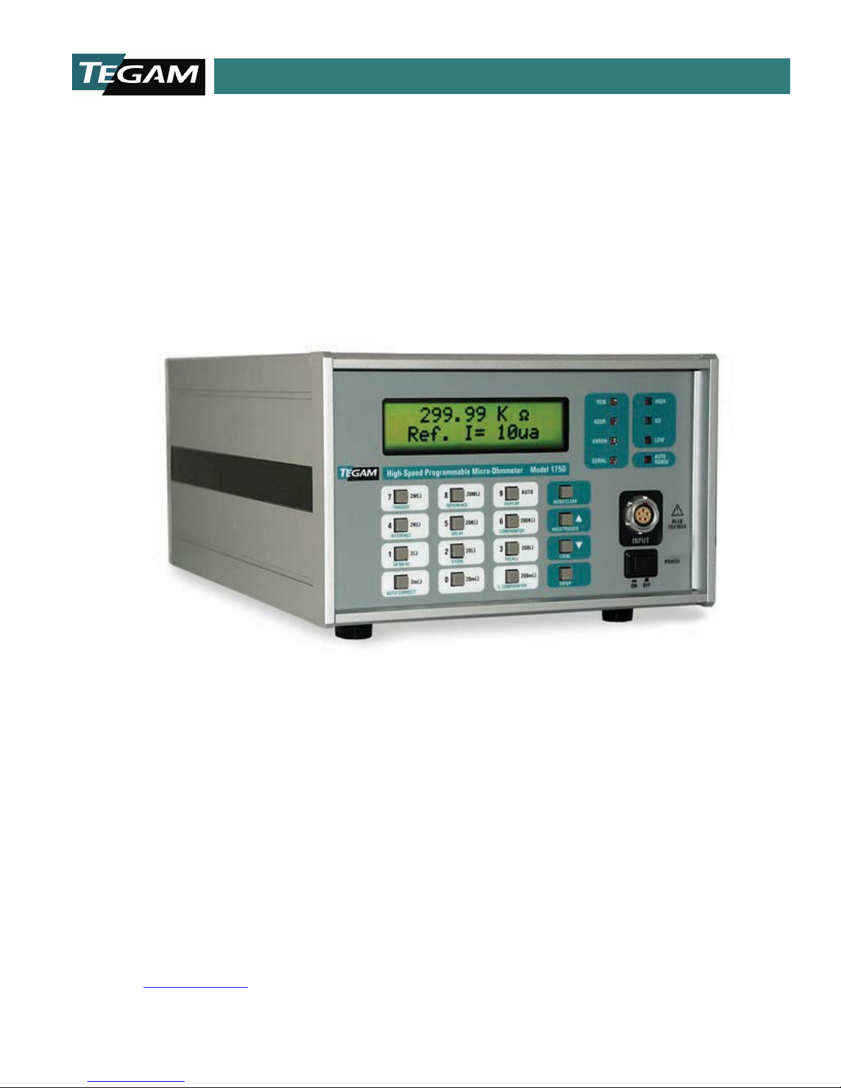
The Model 1750 is a highly versatile, precision digital Microohmmeter designed to provide unmatched
measurement speed and accuracy for production test and quality control applications up to 23 MΩ.
The 1750 microohmmeter automatically rejects thermal and electromagnetic line noise to provide error
free measurements for micro Ohm measurements down to 100 nΩ resolution. The 1750 also
incorporates a single command set to make integration easy for IEEE-488, RS-422 and RS-232
applications.
FEATURE OVERVIEW
The 1750 microohmmeter is desi gn ed a s a c omp l ete bu ndl ed s olu ti on for a wi d e vari ety of r esi stan ce
measurement applications. Listed below are some of the features.
0.02% Basic Accuracy with 4½ digit resolution
The 1750 microohmmeter is de signed to perf orm resi stance m easurem ents wi th a 0.02% basic
accuracy. The 4 ½ digit display produ ces readi ngs from 100 nΩ resolution to 23 MΩ maximum
resistance values.
Bipolar Test Si gnal Eliminat es Thermal EMF errors
The unit is designed to eliminate junction EMFs by introducing a bipolar test signal, which when
combined with digital signal processing, produce an accurate resistance measurement minus
thermal offset errors.
Closed Box Calibration
Full digital calibration is performed within minutes without having to make any internal
adjustments. A calibration enable/disable jumper is accessible by removing the top panel. All
adjustments are made digitally.
Programmable Delay Mode
Settling times are programmable from 1-250 ms to allow measurements of devices with extended
time constants.
Continuous and One-Shot Triggering
The 1750 microohmmeter provides two user-selectable, trigger modes, One-Shot and Continuous
for greater flexibility and optimization of test processes.
10 TEGAM WAY • GENEVA, OHIO 44041 • 440-466-6100 • FAX 440-466-6110 • sales@tegam.com
1-1
Page 6

INSTRUMENT DESCRIPTION
Selectable Reference Currents from 100 nA – 1 A
For power sensi ti ve appl ica tion s such as fuse s a nd resi st ors, mu lti pl e test cur rent select ion s a re
available.
Percent or Absolute Comparator with HI-GO-LO contact and TTL outputs
The 1750 microohmmeter d esign m akes it easy to integra te into n ew or existi ng desi gns. There
are three compar ator outputs which doub le as output b ins 1, 2, and 3. The 1750 inter face include s
relay and TTL outputs for comparator and bin functions.
Rear Panel TTL & Relay outputs for PLCs and interfacing
In addition to GPIB and RS232 interfaces, the 1750 provides a variety of TTL and relay contact
I/O’s designed to make integrating the 1750 into a test stand as versatile as possible.
1 year calibration cycle (after initial 6 month calibration)
After the initial 6 month calibration, the recommended calibration interval for the 1750 is every
twelve months.
10 Preset Storage Locations
Storage location 0 is reserved for recalling factory default settings. Locations 1-9 are user
definable and may be program med manually or via communicat ion interf aces. Thes e settings a re
stored in non-volati le RAM locations.
Fast Mode for high-sp eed measurement
Fast Modes allow speedy measurements of up to 100 reading per second. The time to first reading
is approximately 12 ms, faster than any other Ohmmeter in the mar ke t. This is o btained by us ing
a patent pending DSP technique developed by TEGAM.
½ Rack Width
Two 1750 microohmmeter uni ts are able to be rack mounted, side-by-side, in a standard 19”
rack without modification to the 1750 case.
Manual or Auto Ranging
User defined ranging allows AUTO range or 19 user-selectable ranges of resistance and test
current. All ranges have a 15% over-ranging capability.
10 TEGAM WAY • GENEVA, OHIO 44041 • 440-466-6100 • FAX 440-466-6110 • sales@tegam.com
1-2
Page 7

INSTRUMENT DESCRIPTION
Auto- Correct Function
The auto- correct function compensates for tim e or temp erature d rift b y readin g high ac curacy
internal references and automatically calculating correction coefficients for all ranges. During this
software correction process, the 1750 will delay one reading for 50 ms. The auto correct routine
is performed at power up, after 30 seconds of operation, after 30 minutes of operation, and after
every 65,536 “delayed trigger” readings, (approximately 2 hours).
High Noise Immunity
Built in line cycle integration in combination with shielded test lea ds produce exception al noise
rejection.
GPIB, RS232, or RS-422 Communication Interfaces
Standard GPIB, RS232, or RS422 user-selectable interfaces are standard communications for all
1750 units. A simple command sets ease the task of integration while the use of device dependent
commands allows for specialized function execution.
10 TEGAM WAY • GENEVA, OHIO 44041 • 440-466-6100 • FAX 440-466-6110 • sales@tegam.com
1-3
Page 8
INSTRUMENT DESCRIPTION
connection to components under test.
Kelvin Klip™ replacements for construction
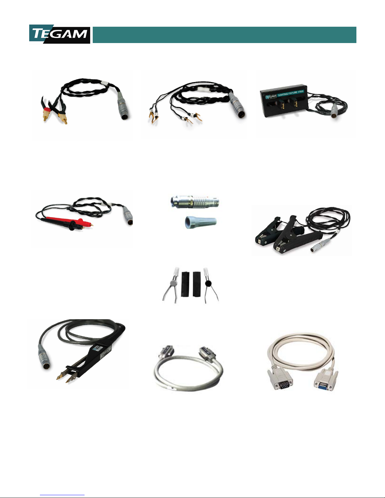
ACCESSORIES SHEET
17501- Kelvin Klip™ Leads
Provides a solid four- terminal
These clips are particularly usef ul for
manual resistance measurement.
Cable length – 3 ft.
17504 – Kelvin Pr obe s
These probes are excellent for
making four-wire surface resistance
measurements on films and other flat
metallic surfaces. Each probe has two
spring-loaded, replaceable tips that
are easily removed and replaced.
Cable length – 3 ft.
17502- Spade Lug Ada pter
Used for connections between the
1750 front panel LEMO and existing
test fixtures.
Cable length – 3 ft.
17503-Sorting Fixture
This sorting fixture allows for
efficient four-wire measur ement of
leaded parts. The test fixture
features spring action contacts for
easy insertion and removal of test
components.
Cable length – 3 ft.
17505 - Male LEMO Connector
For the repair or construction of 1750
test leads.
& Strain Relief
17507 – Large Kelvin Klip™
Leads
Provides a solid 4-terminal connection
KK100- Kelvin Klip™ Rebuild Kit
or repair of Kelvin Klip leads.
to large components hat cannot be
measured with conventional Kelvin
clips. It is robust in construction,
ensuring a firm grip. Used for
connection with large bolts, cables,
plates, etc.
Cable length – 8 ft.
17510 –Chip Tweezers
Four-terminal tweezers make solid
connections to chip components in
manual sorting applications. Capacity of
jaws is 12.7 mm (0.5 in.). Contact tips
are replaceable (part no. 47422)
Cable length – 5 ft.
10 TEGAM WAY • GENEVA, OHIO 44041 • 440-466-6100 • FAX 440-466-6110 • sales@tegam.com
1583 - GPIB (IEEE-488) Cables
1583-3 – 1-meter GPI B buss cable
1583-6 – 2-meter GPI B buss cable
1583-9 – 3-meter GPI B buss cable
1-4
CA-22-36 – RS-232 Straight
Cable 9 pin
Male to Female DB9 straight cable used
to connect the 1750 to a PC via RS-
232.
Cable length – 3 ft.
Page 9
INSTRUMENT DESCRIPTION
PERFORMANCE SPECIFICATIONS
The advertised specifications of the model 1750 are valid under the following conditions:
1. The instrument must be calibrated using the methods and intervals as described in the calibration
section of this user’s manual.
2. The instrument must be in an environment, which does not exceed the limitations as defined under
“Environmental” in the Miscellaneous Specifications in Section 1.
3. T he un i t i s all ow ed to w arm up for a pe ri od of a t lea st 3 0 mi nu tes bef o re me asu rem en ts ar e ta ken .
A warm-up p eriod of 60 min utes is re commend ed after exposur e to or sto rage in a high humidity,
(non-condensing), environment .
4. T he Kelvin seri es lead resi stances must not exceed th e limitati ons as defined in Table1.1 o r Table
1.7.
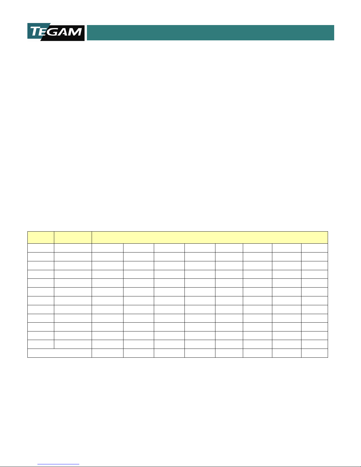
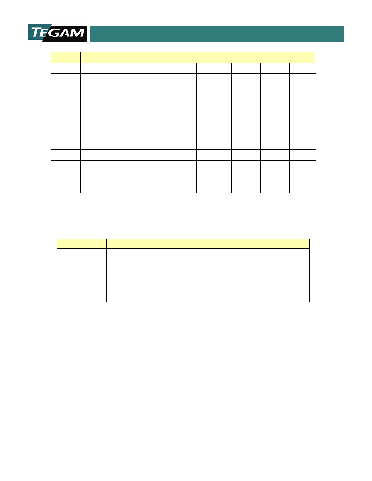
Table 1.1 below is a summary of the ranges and resi stances available with the model 1750. It also
shows the full-scale voltage for each of the reference current ranges. The default ranges are printed in
BOLD. Absol ute maximum lead resist ances for each of the refe rence curren t ranges ar e included on
the bottom row. If these absolute maximum lead resistances are exceeded then significant error will be
introduced into the measurement.
RANGE RESOLUTION
REFERENCE CURRENT
1 A 100 mA 10 mA 1 mA 100 μA 10 μA 1 μA 100 nA
2 mΩ 100 nΩ 2 mV
20 mΩ 1 μΩ 20 mV 2 mV
200 mΩ 10 μΩ 200 mV 20 mV
2 Ω 100 μΩ 200 mV 20 mV
20 Ω 1 mΩ 200 mV 20 mV
200 Ω 10 mΩ 2 V 200 mV 20 mV
2 kΩ 100 mΩ 2 V 200 mV
20 kΩ 1 Ω 2 V 200 mV
200 kΩ 10 Ω 2 V
2 MΩ 100 Ω 2 V
20 MΩ 1 kΩ 2 V
Max. Lead Resistance 500 mΩ 5 Ω 50 Ω 100 Ω 100 Ω 100 Ω 100 Ω 100 Ω
Table 1.1: Full Scale Voltage as a Function of Reference Current
10 TEGAM WAY • GENEVA, OHIO 44041 • 440-466-6100 • FAX 440-466-6110 • sales@tegam.com
1-5
Page 10
INSTRUMENT DESCRIPTION
.02%+5ct
.02%+4ct
.02%+5ct
.02%+2ct
.02%+4ct
.02%+2ct
.02%+4ct
.02%+2ct
.02%+4ct
.02%+2ct
.02%+2ct
.02%+4ct
.02%+2ct
.02%+2ct
.02%+2ct
.02%+2ct
.02%+2ct
.04%+2ct
.04%+2ct
NA
NA
NA
.05%+5ct
NA
.05%+5ct
NA
.05%+5ct
NA
.05%+5ct
.05%+5ct
NA
.05%+5ct
.05%+5ct
.05%+5ct
NA
NA
NA
NA
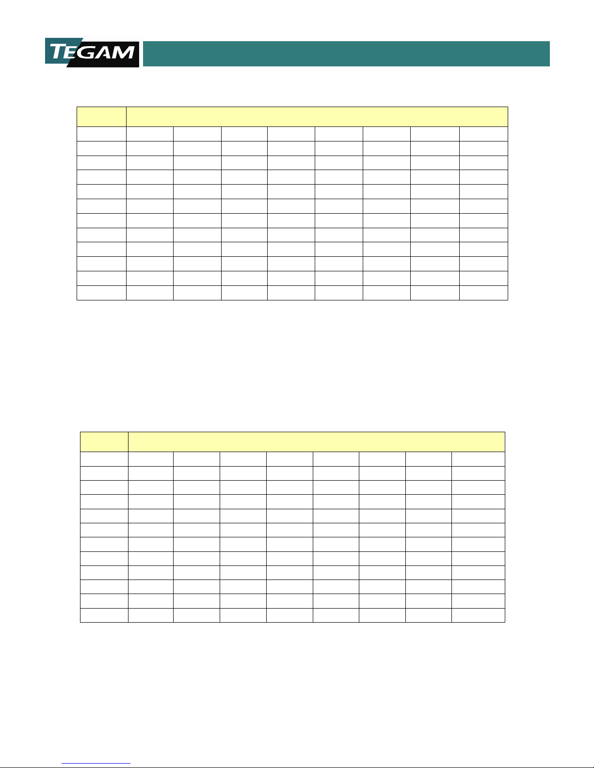
Table 1.2 summarizes the accuracy specifications for the model 1750, in the delayed mode.
RANGE REFERENCE CURRENT
1 A 100 mA 10 mA 1 mA 100 μA 10 μA 1 μA 100 nA
2 mΩ
20 mΩ
200 mΩ
2 Ω
20 Ω
200 Ω
2 kΩ
20 kΩ
200 kΩ
2 MΩ
20 MΩ
Table 1.2: Delayed Mode Accuracies with Respect to Reference Current
(±) ACCURACY; 18-28 °C (64.4-82.4 °F); 1 YEAR (after initial 6 month cycle ).
In the fast mode, the published accuracy for all reference current ranges is +/- (0.05% + 5 counts).
These accuracies are displayed in Table 1.3. Fast Mode is not available for all range s. If the unit is in
Fast Mode and a range is selected that Fast Mode is not ava ilable, then the instrument will default to
Delayed mode.
RANGE REFERENCE CURRENT
1 A 100 mA 10 mA 1 mA 100 μA 10 μA 1 μA 100 nA
2 mΩ
20 mΩ
200 mΩ
2 Ω
20 Ω
200 Ω
2 kΩ
20 kΩ
200 kΩ
2 MΩ
20 MΩ
Table 1.3: Fast Mode Accuracy with Respect to Reference C urre nt
10 TEGAM WAY • GENEVA, OHIO 44041 • 440-466-6100 • FAX 440-466-6110 • sales@tegam.com
1-6
Page 11
INSTRUMENT DESCRIPTION
.004%rdg
+1 count
.004%rdg
+.5 counts
.004%rdg
+1 count
.002%rdg
+.1 counts
.004%rdg
+.5 counts
.002%rdg
+.1 counts
.004%rdg
+.5 counts
.002%rdg
+.1 counts
.004%rdg
+.5 counts
.002%rdg
+.1 counts
.002%rdg
+.1 counts
.004%rdg
+.5 counts
.002%rdg
+.1 counts
.002%rdg
+.1 count
.002%rdg
+.1 count
.002%rdg
+.1 counts
.002%rdg
+.1 counts
.008%rdg
+.5 counts
.008%rdg
MEASUREMENT TIMES
READING RATE
TIME TO FIRST READING
FAST MODE
10ms
100 Readings/ s
12 ms
DELAYED MODE
DELAY=1 ms
36 ms
27 RDG/s
38 ms
DELAY=5 ms
45 ms
22 RDG/s
47 ms
DELAY=10 ms
55 ms
18 RDG/s
57 ms
Delayed Mode
=
2 X (Line Period + Programmed Delay + Process Time)
RANGE REFERENCE CURRENT
2 mΩ
20 mΩ
200 mΩ
2 Ω
20 Ω
200 Ω
2 kΩ
20 kΩ
200 kΩ
2 MΩ
20 MΩ
1 A 100 mA 10 mA 1 mA 100 μA 10 μA 1 μA 100 nA
+.5 counts
Table 1.4: Table of Temperature Coefficients
+/- Temperature Coefficient / °C
(0-18 °C & 28-50 °C; 32-64.4 °F & 82.4-122 °F)
Table 1.5: Measurement Times
Table 1.5 provides approximations of me asurement times and reading rates for delaye d and fast modes.
Note that the time to first reading is longer than subsequent re adings. Examples are provided for various
delay settings. The Delayed Mode Measurement Time is calculated by the following equation:
Measurement
Where the Line Period is 1/f, f = (50 or 60 Hz) and the Programmed Delay Time may range from 1mS
to 250 ms. The Process Time is the time required to process the read data and is equal to about 1.9
ms.
10 TEGAM WAY • GENEVA, OHIO 44041 • 440-466-6100 • FAX 440-466-6110 • sales@tegam.com
1-7
Page 12

INSTRUMENT DESCRIPTION
2 mΩ
D
20 mΩ
D D
200 mΩ
D, F D
2 Ω
D, F D
20 Ω
D, F D
200 Ω
D, F
D, F D
2 kΩ
D, F
D, F
20 kΩ
D, F D
200 kΩ
D
2 MΩ
D
20 MΩ
D
RANGE REFERENCE CURRENT
1 A 100 mA 10 mA 1 mA 100 μA 10 μA 1 μA 100 nA
Table 1.6: Table of Trigger Modes
In Table 1.6, the availability of Fast, (F), or Delayed, (D), Mode Triggering is i ll ustrat ed. Del ayed mod e
is available for each of t h e 1 9 resistance / reference cu r ren t ran ges. The Fa st T riggering m ode is limited
to 8 of the ranges.
10 TEGAM WAY • GENEVA, OHIO 44041 • 440-466-6100 • FAX 440-466-6110 • sales@tegam.com
1-8
Page 13
INSTRUMENT DESCRIPTION
+
REF
0 A
SAMPLE
SAMPLESAMPLE
SAMPLE
SAMPLES FOR HIGH AND LOW STATES ARE TAKEN
FOR 32 CYCLES, THEN A READING IS PROCESSED.
THE PROCESS IS REPEATED CONTINUOUSLY.
READING COMPLETE
+
REF
0 A
SAMPLE
SAMPLE
SAMPLE
SAMPLE
CONTINUOUS SAMPLES ARE TAKEN FOR 32 CYCLES,
THEN A READING IS PROCESSED
READING COMPLETE
+
REF
0 A
- REF
A
A
A
A
ACB
B
B
B
B
C
C
CD D
SAMPLE
COMPLETE READING
SAMPLE
COMPLETE READING
SAMPLE
SAMPLE
+
REF
0 A
- REF
A
ACBB C D
SAMPLE
COMPLETE READING
SAMPLE
+
REF
0 A
- REF
A
A BBC
C D
SAMPLE
COMPLETE READING
SAMPLE
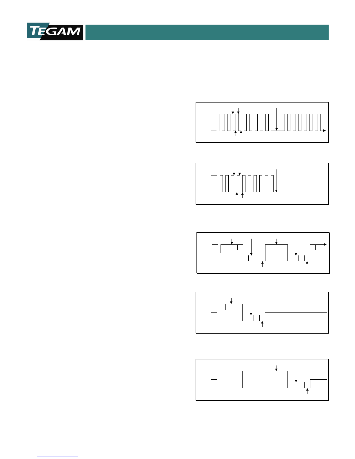
Fast Continuous:
Readings are taken towards the end of each +REF/ 0A state.
The test signal is an alternating reference current from + REF
to 0A, with automatic thermal and noise rejectio n.
Fast One-Shot:
This mode must receive an external trigger and is a shortened
version of the Fast Continuous mode. A total of 64 data
samples are taken. 32 samples on + cycles and 32 samples
on the 0 Ampere cycles. These samples are digitally processed
to produce reading
Delayed Continuous:
Continuous Alternating refer ence current from + REF to
“A” represents the programmable delay time from 1 to 250 mS.
“B” represents the line cycle time
Cycle
“C” is the time required for broken lead detection to take p lace
“D” is when the reading is processed and updated
Delayed One-Shot
Alternating reference current from + REF to – REF.
Triggering via GPIB, RS232 or rear trigger input will cause a
single cycle of reference curren t .
Delayed One-Shot
(Triggered Via Front Panel)
Alternating reference current from + REF to – REF.
Triggering via the front panel. Once trigg er e d , two reference
cycles are released of which the latter pulse will be used to
take the actual reading.
REFERENCE CURRENT MODES
There are several types of pulses available for making measurements. Below is a summary of
characteristics for each type of trigger mode and the sequence of events that occur during an actual
measurement.
Integration)
- 1/f (Sampled Input for Line
10 TEGAM WAY • GENEVA, OHIO 44041 • 440-466-6100 • FAX 440-466-6110 • sales@tegam.com
– REF.
.
1-9
Page 14

INSTRUMENT DESCRIPTION
MISCELLANEOUS SPECIFICATIONS
Display Modes:
• Resistance; Absolute Comparator; % Comparator
Digital Inte rfaces:
• IEEE-488
• RS-232
• RS-422
• External Trigger Input, and Reading Done TTL Outputs - BNC Connectors
Display:
• 4½ Digit alpha numeric readout; 2 X 16 Characters, Dot Matrix Display with backlight
Measurement Method:
• 4 terminal Kelvin connection to DUT.
Input Connector:
• Heavy Duty Type LEMO Connector for signal integrity and long life.
Input Protection:
• ± 15 V Continuous.
• Maximum Common Mode Input Voltage is 42 V peak.
Overload Current:
• Delayed Mode: 100% Overshoot, <25 μs
• Fast Mode: 200% Overshoot, < 30 μs
Noise Rejection:
• 60 dB Typical at Line Frequency
Maximum Open Circuit Compliance Voltage, (Typical):
Closed circuit compliance voltages are much lower; see Table 1.1, Full Scale Voltage as a
Function of Reference Current
• 18 Vp-p maximum (1 mA-1 A Test Current)
• 14 Vp-p maximum (100 nA-100 uA Test Current)
Environmental:
• Operating Temperature: 0 to 50 °C (32 to 122 °F), <80% RH; (Non-Condensing)
• Storage Temperature: -35 to 60 °C (-31 to 140 °F), <90% RH (Non-Condensing)
EMC:
• EN 61326-1:2013
10 TEGAM WAY • GENEVA, OHIO 44041 • 440-466-6100 • FAX 440-466-6110 • sales@tegam.com
1-10
Page 15

INSTRUMENT DESCRIPTION
MISCELLANEOUS SPECIFICATIONS (Continued)
Dimensions:
• Depth: 13.0” (33.0 cm)
• Width: 8.50” (21.6 cm)
• Height: 5.20” (13.2 cm)
Weight:
• 9.25 lbs (4.20 kg)
Rear Interface Relay Cont act Sp eci fications:
The relay contact I/Os are rated at 125 VAC @ 500 mA or 30 VDC @ 1 A.
Calibration:
Calibration of the 1750 is permitted via the front panel with no internal a d justments.
Calibration requires the temporary placement of a jumper, P9 to the J9 position.
AC Power Requirements:
Input: <100 VA, 108-132 VAC or 216-264 VAC, at 50/60 Hz.
Fuse:
• For 108-132 V Operation; use 0.8 A @ 250 V, 5X20 mm, fast acting, TEGAM PN#FU-800
• For 216-264 V Operation; use 0.5 A @ 250 V, 5X20 mm, fast acting, TEGAM PN#FU-500
10 TEGAM WAY • GENEVA, OHIO 44041 • 440-466-6100 • FAX 440-466-6110 • sales@tegam.com
1-11
Page 16
INSTRUMENT DESCRIPTION
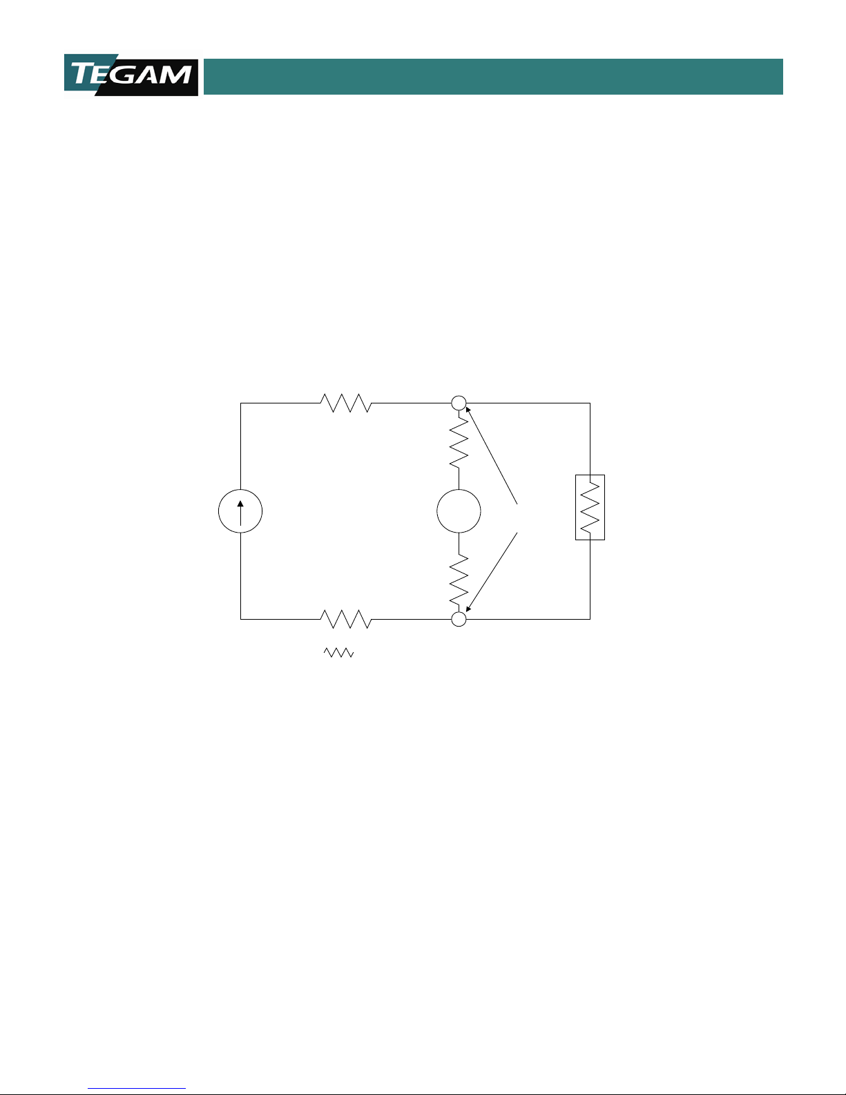
V
REFERENCE
CURRENT
SOURCE
VOLTAGE
SENSE
DUT
= SERIES LEAD RESISTANCE
CONTACT
POINTS
TEST LEAD REQUIREMENTS
From the factory, the 1750 microohmmeter is equipped with the choice of either 17501 Kelvin Klips or
17502 Kelvin Spade Lugs. These are both 4-wire Kelvin input cables. Four-wire Kelvin-type cables must
be used with the 1750 in order to obtain an accurate resistance measurement.
The Kelvin measurement technique allows for a much more accurate reading over the two wire method.
This is because it eliminates l ead resistance. Thi s i s d on e by designatin g two o f th e f ou r con du ctors as
source lead s. These sou rce leads p rovide th e precisi on test curren t that wil l be referen ced in ma king
the resistance measurement. Since current is the same throughout a series circuit, the lead resistance
of the test leads will not have any effect on the reference current.
Figure 1.1: Electrical Representation of a typical Four-Wire Kelvin Measurement
The other two conductors are designated as voltage sense leads. These leads originate from high
impedance, v olt measurem ent circuit . When these l eads are termi nated at the poi nts of contact, an
exact resis ta n ce r ea d ing may be cal cu lated by the 175 0 m icroprocesso r . Th e s eries lead resistance of
the volta ge s ens e l eads i s neg l igi ble w i th resp e ct t o t he hi gh i mp edan ce of t he vol t age m ea sur ement
circuitry within the 1750 microohmmeter.
Four-wire Kelvin measurements are mainly used for low resistance measurements where lead
resistance er ro rs must be elimi nated.
Even though the four-wire Kel vin measurement minimizes th e effect that l ead resistance h as on the
overall measurement, there is a maximum allowable lead resistance. If this value is exceeded, then the
resulting measurement will be erroneous. The test current source dictates this limitation and lead
resistance limits are based on the amount of reference current that is flowing. The table below
summarizes these limitations.
10 TEGAM WAY • GENEVA, OHIO 44041 • 440-466-6100 • FAX 440-466-6110 • sales@tegam.com
1-12
Page 17

INSTRUMENT DESCRIPTION
REFERENCE CURRENT 1 A 100 mA 10 mA 1 mA 100 μA 10 μA 1 μA 100 nA
MAXIMUM LEAD RESISTANCE 500 mΩ 5 Ω 50 Ω 100 Ω 100 Ω 100 Ω 100 Ω 100 Ω
Table 1.7: Maximum Allowable Lead Resistance (per lead).
To assure measurement accuracy, the above lead resistance limits should not be exceeded.
In order to make accurate measurements on resistances greater than 200 kΩ, it is highly recommended
that the GROUND terminal, located on the rear panel, be connected to the DUT test fixture shield. The
test fixture shield must surround the DUT.
Also, for resistance measurements greater than 200 kΩ, the programmable delay time should be set to
a minimum of 100 ms to allow adequate settling of the reference current.
10 TEGAM WAY • GENEVA, OHIO 44041 • 440-466-6100 • FAX 440-466-6110 • sales@tegam.com
1-13
Page 18
INSTRUMENT DESCRIPTION
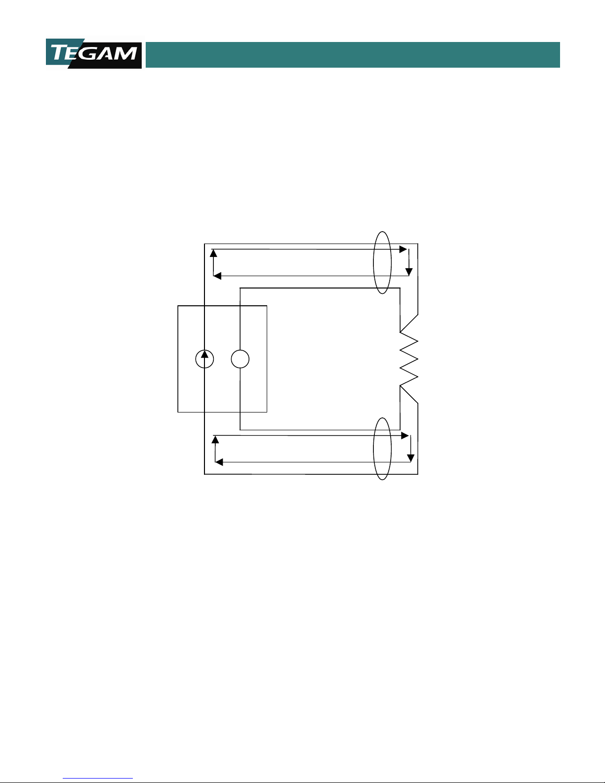
V + -
Positive Kelvin Loop
Negative Kelvin Loop
DUT
BROKEN LEAD DETECTION
A broken lead detection feature is enabled for ranges below 200 Ω when operating in either of the two
Delayed trigger modes. This feature is a function of the firmware and detects an open circuit by
monitoring the test current characteristi cs. The ill ustrati on below r epresents the Kel vin lea ds and th e
connection acros s a d evi ce u nd er test. Not e tha t th ere are t hr ee loop s drawn wi th the a rrows . Each of
these arrows shows the continuity test that is effectively performed by firmware during each read cycle.
If either the negative Kelvin loop, Positive Kelvin loop, or connection between the leads is broken, then
a broken lead state will be detected and the message “*****” is displayed on the LCD.
Fig 1.2: Continuity Test Paths for Broken Lead Detection
10 TEGAM WAY • GENEVA, OHIO 44041 • 440-466-6100 • FAX 440-466-6110 • sales@tegam.com
1-14
Page 19

PREPARATION FOR USE
!
SECTION 2
PREPARATION FOR USE
UNPACKING & INSPECTION
Each 1750 microohmmeter is put through a series of electrical and mechanical inspections before
shipment to the customer. Upon receipt of your instrument unpack all of the items from the shipping
carton and inspect for any damage that may have occurred during transit. Report any damaged items
to the shipping agent. Retain and use the original packing material for reshipment if necessary.
Upon Receipt, inspect the carton for the fo llowing items:
Model 1750 Precision Microohmmeter
Model 1750 User’s Manual
Either one of the following: 17501 Kelvin Klips™ or 17502 Spade Lug Adapter
SAFETY INFORMATION & PRECAUTIONS
The following safety information applies to both operation and service personnel . Safety precautions
and warnings may be found throughout this instruction manual and the equipment. These warnings
may be in the form of a symbol or a written statement. Below is a summary of these precautions.
Terms in This Manual
CAUTION statements identify conditions or practices that could result in damage to the equipment or
other property.
WARNING statements apply conditions or practices that could result in pers onal injury or loss of life.
Terms as Marked on Equipment
CAUTION indicates a personal injury hazard not immediately accessible as one reads the marking, or a
hazard to property including the equipment itself.
DANGER indicates a personal injury hazard immediately accessible as one reads the marking.
10 TEGAM WAY • GENEVA, OHIO 44041 • 440-466-6100 • FAX 440-466-6110 • sales@tegam.com
2-1
Page 20
PREPARATION FOR USE
! !
!
SAFETY INFORMATION & PRECAUTIONS (Continued)
Symbols
As Marked in This Manual:
This symbol denotes where precautionary information m ay be found.
As Marked on Equipment:
Attention – Please refer to the instruction manual.
Power ON/OFF switch
Danger – High or hazardous Voltage
Earth Ground Terminal
Grounding the Equipment
This product is grounded through the grounding conductor of the power cord. To avoid electrical shoc k
or other potential safety hazards, plug the po wer cord into a properly wir ed receptacle before using this
instrument. The proper grounding of this instrument is essential for safety and optimizing instrument
operation.
Danger Arising from Loss of G round
If the connection to ground is lost or compromise d, a floating potent ial could develop in the instrument.
Under these conditions all accessible parts, including insulating parts s uch as keypads and buttons could
develop a hazardous voltage and put the user at risk.
Use the Proper Fuse
To avoid fire hazard, use only the correct fuse type as specified for the AC power supply in the
“Miscellaneous Specifications” or “Repair Parts” sections of this manual.
Refer fuse replacement to qualified service personnel.
Do Not Use in Explosive Environments
The 1750 microohmmeter is not designed for operation in explosive environments.
10 TEGAM WAY • GENEVA, OHIO 44041 • 440-466-6100 • FAX 440-466-6110 • sales@tegam.com
2-2
Page 21

PREPARATION FOR USE
!
Do not Operate without Covers
This device should be operated with all panels and covers in place. Operation with missing panels or
covers could result in personal injury.
Preventive Maintenance
Preventive maintenance performed on a regular basis will improve the reliability of this instrument.
It may include cleaning (please refer to Section 6), visual inspection, or even monitoring the operating
environment.
FOR QUALIFIED SERVICE PERSONNEL ONLY
SERVICING SAFETY SUMMARY
Do Not Service Alone
Do not perfo rm servi ce or adj ustm ent on th is produ ct unl ess anoth er per son cap able of renderi ng first
aid is present. In stallati on and mai ntenance proc edures des cribed in this man ual are to be p erformed
by qualified service personnel only.
Use Care Wh en Servicing with Power On
Dangerous voltages may exist at several points in this product. To avoid personal injury or damage to
this equipment, avoid touching exposed connections or components while the power is on. Assure that
the power is off when removing panels, soldering, or replacing co m ponents.
Power Source
This product is intended to connect to a power source that will not apply more than 250 V
the supply conductors or between either supply conductor and ground. A protective ground connection
by way of the grounding conductor in the power cord is essential for safe operation.
between
RMS
10 TEGAM WAY • GENEVA, OHIO 44041 • 440-466-6100 • FAX 440-466-6110 • sales@tegam.com
2-3
Page 22
PREPARATION FOR USE
!
LINE SELECTOR
671175400
LINE VOLTAGE SELECTION
CAUTION: DO NOT APPLY POWER TO THE INSTRUMENT BEFORE READING THIS SECTION:
Unless other wise specified, the M odel 1750 microohmmeter i s delivered from TE GAM with its power
supply set for 120 V, 60 Hz operation. However, the 1750 design allows it to operate under 120/240
V @ 50/60 Hz op erati on. It is recomm ended th at th e li ne vol tage, f requ ency setti ng an d fus e typ e be
verified before powering the unit.
The following procedure describes the steps necessary to change the 1750 power settings from factory
default settings to 240 VAC @50 Hz.
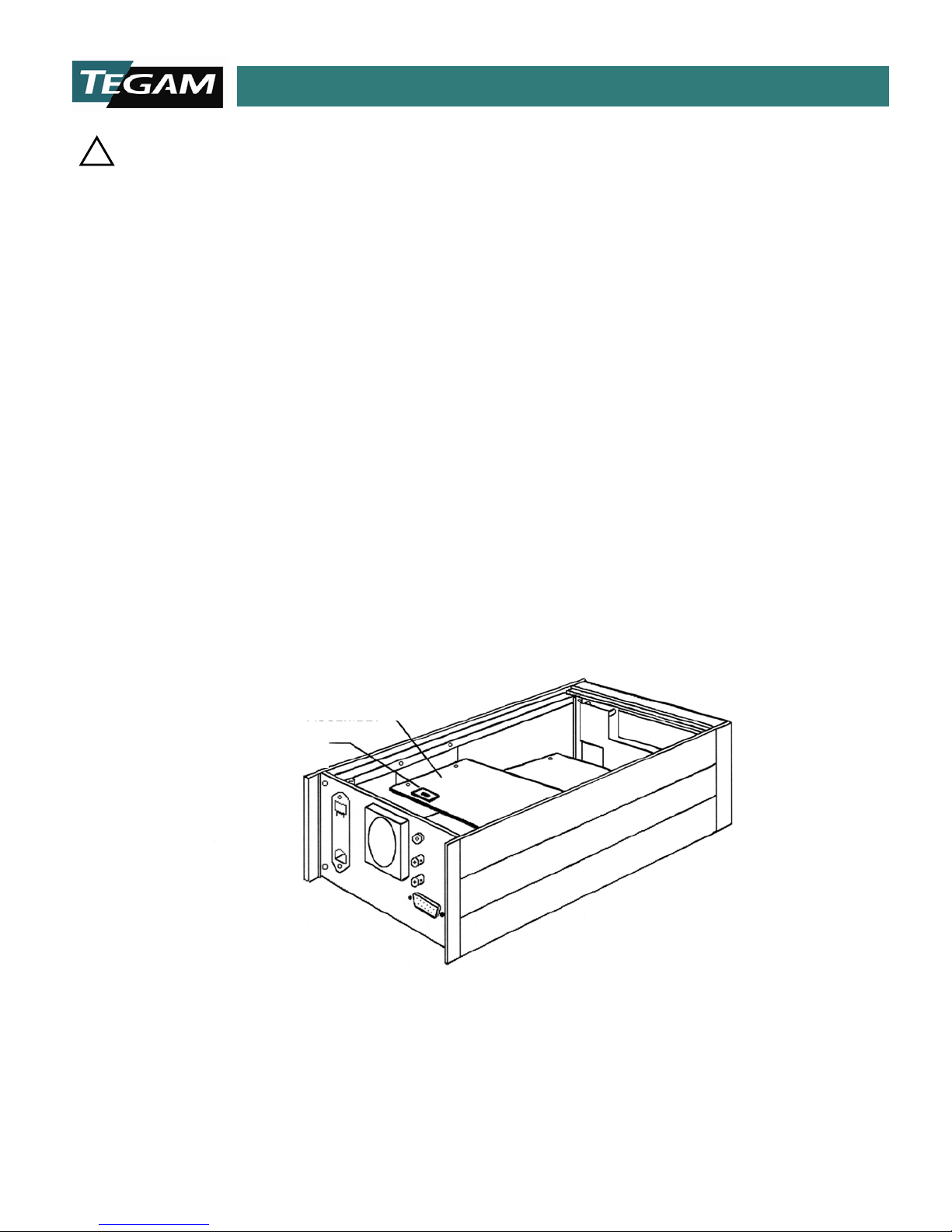
1. Verify that there is no power connected to the unit. Remove the top co ve r.
2. Change the line selector switch on the power supply printed circuit board from 120 VAC to 240
VAC. The switch is located toward the rear panel of the 1750 on the top most PCB board. Refer
to the figure below:
3. Replace the top cover and connect the 1750 to its power source. Power the unit by depressing
the power switch located on the front panel.
4. Press the [MENU/CLEAR] key then press the 50/60 Hz key, (Key #1). Scroll the menu by pressing
either the [▲] or [▼] keys. Once 50Hz is displayed on the LCD then press [ENTER]. The 1750 is
now set for 240 VAC @ 50 Hz operation .
POWER SU PPLY
ASSEMBLY
SWITCH
Fig 2.1: Line Voltage Selection Location
NOTE: The 1750 microohmmeter uses line cy cle in t egrat ion in order to p rev ent in ter fer enc e f rom a ff ectin g the
instrument read ings . F or p rop er rea d ing s, th e f req uen cy se tting of th e in stru men t mu st m atc h th e lin e su pply .
You can change th e frequency setting simply by follow ing the instructions in step #4.
10 TEGAM WAY • GENEVA, OHIO 44041 • 440-466-6100 • FAX 440-466-6110 • sales@tegam.com
2-4
Page 23

QUICK START INSTRUCTIONS
Parameter
Setting
Parameter
Setting
1
Range
2 Ω @100 mA
8
Communication
*RS232
2
Trigger
Delay Continuous
9
Store Setup
-
3
Delay Time
111 ms
10
Recall Setup
-
4
Display Mode
Resistance
11
Line Frequency
60 Hertz
5
Compare Limits
19999; 00000
12
PIN Function
*Disabled
6
% Compare Limits
10.00%; 10.00%
13
Calibration
*Disabled
7
Nominal
10000
SECTION 3
QUICK START INS TR UCTIONS
GENERAL
The Model 1750 microohmmeter is a versatile product, which can be used in many different
configurations. De pending on the applicat ion, there are configur ations of the 1750 microohmmeter that
will help optimize te st cond itions invo lving acc uracy, me asurement speed, and v ersatility. The bes t way
to maximize the effectiveness of a pro duct and test setup is by ha ving a thorough unders tanding of the
instrumentation and the test parameters, which can a ffect the readings.
The Quick Start section is designed to give the user a general i n st ru ct i on s et for the speedy setup a n d
measuremen t of resista nce values . Whenever additi onal informat ion is app licable, a r eference w ill be
made to other parts of this manual so that the user, at their discretion, can decide whether or not to
pursue ad d itional informa t io n .
POWER THE UNIT
The power supply of the Model 1750 is designed for 50-6 0 Hz operat ions and a v olt age ran ge of 1 08132 & 216-264 VAC. Review the line voltage selection procedure on page 2-4 before proceeding.
Power the unit and allow at least 30 minutes for the unit to warm up. Make sure that the safety
precautions on pages 2-2 and 2-3 hav e be en re vi ewed an d un der sto od. Ve ri fy th at t h e en vi ron men tal
conditions, listed on page 1-10 are met.
FACTORY SETTINGS
Before perfor ming t he actual resistance m easuremen t, there a re a num ber of test paramet ers, whic h
must be defined. The factory settings can be used for most general resistance measurements.
The 1750 microohmmeter is shipped from the factory with instrument settings as follows:
These settings can be recalled by sending a device clear command via RS232, RS422 or GPIB interface.
* When a device clear command is sent via communications interface, this value does not change.
CUSTOMIZING PARAM ETER SETTINGS
10 TEGAM WAY • GENEVA, OHIO 44041 • 440-466-6100 • FAX 440-466-6110 • sales@tegam.com
Table 3.1: Factory Default Settings
3-1
Page 24

QUICK START INSTRUCTIONS
The 1750 factory settings are usually adequate to meet the needs of most manual, low inductance,
resistance measurement applications. However, in high-speed, automated resistance measurement, it
is often desirable to optimize the instruments settings to obtain the highest accuracy and throughput.
For this rea son, t he Mod el 175 0 offers 13 user -defin ed test p aramet ers. In-depth information for any
of these Setup options may be found in Section 4, O perating I nstruct ions. Before changing any o f these
factory default settings, it is highly recommended that Section 4 is thoroughly reviewed and understood.
Special attention should be directed toward allowing adequate settling times for high resistance
measurement applications and defining the proper reference current in fuse testing applications.
The front keypad is setup for ma ximum functionality. Each key has multiple functions assigned to it.
These funct ions are l abeled acc ording t o their pri mary and se condary functions . To access the Setup
options, simply press the [MENU] button on the front panel. The message “
appear on the screen. From this display, you can access any of the 11 menu options labeled with teal
text located below the key. Pressing any of these buttons will allow yo u to access the instrume nt’s Sub Menu for entering custom settings. You can modify instrume nt Sub-settings by either pressing the [▲]
or [▼] scroll keys or by manually entering a numeric value.
See Section 4 for an in depth description of the keypad functionality and how to store and recall custom
settings.
TEST LEAD REQUIREMENTS
The Model 1750 microohmmeter measures resistance by using the four-wire Kelvin technique. This type
of measurem ent virtually elimi nates lead resistanc e error. A set of Kelvi n Klip™ leads or Spade Lu g
Adapters are supplied with the new instrument. In addition, optional sorting fixture or Kelvin Probes
are available. These accessories are designed to function with the Model 1750 in all operating currents
and ranges.
In certain applications, the need arises for a custom assembled test connection or fixture. When
constructing a solution of this type, detail has to be directed towards the maximum allowable series
lead resistan ce. There is a speci fic series lead resi stance limit estab lished for each cu rrent range. If
these limits are exceeded, a significant amount of error may be introduced into the measurement.
Detailed information on Kelvin-type measurements an d lea d re sist ance er ror m ay b e foun d in Section
1 under the “Test Lead Requirements” section. See Table 1.7 for maximum allowable series lead
resistances.
MEASURING RESISTANCES LARGER THAN 200KΩ
For stable resi stance mea surements on resista nces greater t han 200 kΩ, it is recommended that the
GUARD terminal on the rear panel be conn ected to th e DUT te st fi xture GR OUND t ermi nal . The actu al
resistance being measured should be shielded within a grounded test fixture.
If it is unknown whether the test circuit is inductive or capacitive in nature, the delay time should be
set to a minimum of 100mS in order to allow adequate measurement settling time. This settling time
should be increased as the measured resistance value is increased.
Menu Number?” will
10 TEGAM WAY • GENEVA, OHIO 44041 • 440-466-6100 • FAX 440-466-6110 • sales@tegam.com
3-2
Page 25

OPERATING INSTRU CTIONS
SECTION 4
OPERATING INSTRUCTIONS
BASIC OPERATION
The Model 1750 microohmmeter is a highly versatile product, designed for use in many different
applications. There are ideal configurations of the 1750 microohmmeter for each type of application.
These configurations optimize test conditions while enhancing accuracy, measurement speed, and
versatility.
In order to maximize the effectiveness the 1750’s operation the user should have a thorough
understanding of the instruments operation.
This section is designed to give the user an in depth description of the numerous parameters and
operating modes available from the Model 1750. The user will be e xpose d to additiona l topics that wil l
enhance the integration of the Model 1750 into their application.
DEFAULT PARAMETERS
Each unit is delivered from the factory with predefined test parameters and mode s. These pred efined
settings are intended for general-purpose resistance measurement and ease of use.
Section 3, Quick Start Instructions, contains information on factory default settings.
10 TEGAM WAY • GENEVA, OHIO 44041 • 440-466-6100 • FAX 440-466-6110 • sales@tegam.com
4-1
Page 26

OPERATING INSTRU CTIONS
Liquid C rystal Display - Indicates the resistance
either HOLD the measurement when operating in Co ntinuo us
for factory use only.
Power Switch – Powers the 1750.
]
High Speed Programmable Micro-Ohmmeter Model 1750
High Speed Programmable Micro-Ohmmeter Model 1750
Liquid Crystal
Local Mode
Kelvin Input
Comparator
MENU Selection
Power Switch
Parameter
Hold/Manual
Numeric
Communication
FRONT PANEL DESCRIPTION
Display
Keypad
Trigger Key
Figure 4.1: Front Panel Layout
Menu Enter
Key
Status LEDs
Output LEDs
Key
LEMO Connector
Key
measurement, resistance range, comparator settings,
communication type, and other operating conditions. See
“Display Modes” in this Section for details of displ ay
operation.
Numeric Keypad – Numeric keypad includes 0-9 keys for
entering values for menu items, delay times or
comparator/bin limits.
Hold/Manual Trigger Key – This key allows the user to
Trigger Modes or to TRIGGER a reading in the One-Shot
Modes. It also functions as the scroll up, [▲], key when the
unit is in parameter mode.
Parameter Menu Enter Key – The [ENTER] key is used for
inputting parameter settings for any of the menus or for
storing numerical data.
Local Mode K e y –Pressing this key permits the user to
access front panel controls while the unit is operating in
remote mode. The unit returns to remote mode from local
mode after receiving a command from the GPIB or RS232
interface.
The local key also functions as the scroll down, [▼], key
when the menu mode is selected.
If the internal calibration jumper is enab le d , pres s ing this
button will switch the 1750 into debug mode. This feature is
Kelvin Input LEMO Connector – Heavy Duty Input
Connector for Kelvin Klips™, Spade Lug Adap ter, Ke lvin
Probes or Test Fixture using 5 conductor, male LEMO.
Menu Scroll Keys – The scroll keys will allo w the
navigation of the Menu Screens by pressing either the [▲
or [▼] keys.
Menu Selection Key – Pressing this key will toggle the
function of the numeric keypad for accessing and defining
instrument parameters.
Comparator Output LEDs - LEDs indicate status of
comparator after measurement cycle. LED status
corresponds to comparator relay and TTL outputs on rear
panel connector, J8.
Communication Stat us LED s – Indicate the error and
status of communications RS232, RS422 & GPIB.
10 TEGAM WAY • GENEVA, OHIO 44041 • 440-466-6100 • FAX 440-466-6110 • sales@tegam.com
4-2
Page 27

OPERATING INSTRU CTIONS
20 CFM maximum airflow. Operation is 5
V @ 240 mA.
REAR PANEL DESCRIPTION
Figure 4.2: Rear Panel Layout
BNC Reading Done TTL Output – Open Collector TTL
Output. Output is at +5 V until a complete reading cycle
has occurred. A negative going pulse occurs for about 4 .25
ms then the output state returns to +5 V.
BNC Trigger TTL Input – A TTL low into this input will
activate a trigger command. A trigger will also occur if the
input is shorted to ground via relay or other contact for a
minimum of 10 ms.
J8 – Relay and TTL I/O Conn ec tor – See Section 5,
Interfacing to the PC for pin out details.
VAC Input – 120 /2 40 V @ 50/6 0 Hz , power input. Line
fuse is accessible through this input.
GPIB (IEE-488.2) Port - See Section 5, Interfacing to
the PC for pin out details.
RS232 Port - See Section 5, Interfacing to the PC for
pin out details.
RS422 Port - See Section 5, Interfacing to the PC for
pin out details.
Guard Terminal – Banana connection to the 1750 test
signal current source (common), typically us ed for
reducing noise in high resistance, (>20 kΩ)
measurements.
Cooling Fan –
10 TEGAM WAY • GENEVA, OHIO 44041 • 440-466-6100 • FAX 440-466-6110 • sales@tegam.com
4-3
Page 28

OPERATING INSTRU CTIONS
Digital Software
Version
Product
Identification
DISPLAY MODES
When the power key is depressed, AC power is applied to the 1750. During the power cycle, the
1750 operating system initiates and the display will show the product identif icat ion information. The
1750 dig ita l so ft war e re vis ion s a ppe ar be low the pr odu ct id ent if icat ion. Th is dis pla y w ill b e v isib le fo r
about two sec onds an d then the 175 0 will resume op erati on und er the sam e set-up paramet ers a s
when it was last turned off.
Tegam Model 1750
Revision 2.XX
Figure 4.3: Initialization Display
After initialization, the 1750 microohmmeter will display one of three t ypes of displ ays, Resistance,
Absolute Comparator, or % Comparator. The particular display mode will be dependent upon the
mode that the 1750 was operating in before the last power down. The following sections will describe
each of the display modes and their respective display fields.
10 TEGAM WAY • GENEVA, OHIO 44041 • 440-466-6100 • FAX 440-466-6110 • sales@tegam.com
4-4
Page 29

OPERATING INSTRU CTIONS
Resistance Reading
0.1750 mΩ
Ref. I= 1Amp
Indication of Over
Reading Hold
*.**** m
Ref. I= 1Amp h
Reference Current
Resistance Mode
The 1750 factory default setting is the Resistance Mode. Below is a representation of the Resistance
Mode display and a brief description of each of the display fie lds.
Resistance Reading
This field is reserved for display of the resistance measurement value or status. There are 4 ½ digits
of resolution for all ranges of resistance and test currents. The reading is updated once every
measurement cycle in the Continuous Trigger Mode. The actual cycle time of the continuous mode is
dependent on whether the unit is in Delayed Continuous or Fast Continuous Mode. Refer to Section
1, for detai led timing diagrams a nd a formula for cal culating total measurement times. When the
1750 is operating in the Delayed One-Shot or Fast One-Shot Mode, the resistance reading is updated
one measur ement cycle aft er a manual trigger is recei ved. These ac tual measurem ent times may
also be determined by referencing Section 1.
Range or Open Lead
Open Lead Detection
The 1750 includes an Open Lead Detection feature, which is active in the 20 Ω, 2 Ω, 200 mΩ, 20
mΩ, and 2 mΩ ranges. It verifies the continuity of the test leads and contacts when the 1750 is
operating in either of the two delayed trigger modes, (Delayed Continuous or Delayed Trigger). The
Kelvin measurement technique requires that four wires be used in making a measurement. If any of
these leads or a combination of these leads is open, then the instrument shall display “
which is the equivalent of an ov er range co nditio n. For RS23 2 and GPI B op era tion, the unit w ill s e nd
a “2.9999” ASCII string, which is also the equivalent of an over range condition.
Condition
Figure 4.5: Over Range or Open Lead Condition
10 TEGAM WAY • GENEVA, OHIO 44041 • 440-466-6100 • FAX 440-466-6110 • sales@tegam.com
Figure 4.4: Resistance Mode
Ω
4-5
Status
*****”,
Page 30

OPERATING INSTRU CTIONS
Reading Hold
When the [HOLD/TRIGGER] button is pressed, the most current reading may be latched and held on
the LCD until the [HOLD/TRIGGER] button is pressed again. The status of the reading hold feature
is indicated on the lower left hand corner of the LCD. An “h” indicates a hold condition. This feature
is only functional in the Continuous Trigger Modes.
One Shot Trigger
When the 1750 microohmmeter is operated in the One-Shot Trigger Mode, an “S” will appear in place
of the “h” in the LCD lower right hand corner. This symbol notates that the instrument is in the One
Shot mode an d requires ext ernal trigg ering from th e front panel , communicati ons interface o r the
BNC TTL trigger input on the rear panel.
Resistance Range and Reference Current
There are 19 possible resistance and reference current range combinations that the 1750 will operate
under. The pr esent reference cur rent level is di splayed on the bottom of t he LCD. Once the u ser
becomes more familiar with the display, the actual resistance and reference current combination c an
be determined by observing the placement of the decimal point on the reading and the indicated
reference current level. When the 1750 is in AUTO RANGE mode, then the AUTO RANGE LED on the
right hand side of the front panel will be illuminated.
10 TEGAM WAY • GENEVA, OHIO 44041 • 440-466-6100 • FAX 440-466-6110 • sales@tegam.com
4-6
Page 31

OPERATING INSTRU CTIONS
H=20000 L=10000 h
*.**** M
High Absolute
Low Absolute
Absolute Comparator Mode
In the Absolute Comparator Display Mode, the screen will look like the Resistance Display Mode
except that the reference current indication is replaced by two additional fields of data. On the left
side is the high limit, absolute value. On the right side is the a bsolute low, comparator limit.
Comparator Limit
Ω
Comparator Limit
Figure 4.6: Absolute Comparator Mode
The above display indicates that the meter is in the 2 MΩ range. The high limit is set to 20,000
counts of ful l sca l e, whi ch i s 2 MΩ. The low limit is set to 10,000 counts, which is the equivalent to
1 MΩ in this scale. Note that the comparator limits are programmed in counts rather than Ohmic
units. This mean s that the comparat or resistance val ues are determi ned by both the act ive range
and the user defined limit values.
High & Low Absolute Comparator Limit
Fields indicate the user-defined upper and lower limits for the absolute comparator function. If the
measured resistance reading exceeds the high limit, and the comparator mode is active, then the
corresponding “HI” state will transfer to the Compar ator State LED. If the current re ading falls o n or
between the HI and LO comparator limits, then the “GO” LED becomes illuminated. And finally, if the
reading falls below the low limit then the “LO” comparator output is activated. The TTL and Relay
comparator outputs in the rear panel follow the front panel comparator LED states. All comparator
outputs are disabled when the 1750 is operating in the resistance mode.
10 TEGAM WAY • GENEVA, OHIO 44041 • 440-466-6100 • FAX 440-466-6110 • sales@tegam.com
4-7
Page 32

OPERATING INSTRU CTIONS
H10.00% L10.00% h
**.***MΩ N10.000
Resistance
High %
Nominal Value
Low %
Comparator Limit
% Comparator Mode
Reading
Comparator Limit
Figure 4.7: % Comp arator Mode
High% & Low% Absolute Comparator Limit
The % Comparator Display Mode is similar to the Ab solute Com parator Mode in that the use r defines
the upper and lower limits of the resistance measurement. However, these limits are defined in terms
of a high and low percentage of a nominal value instead of an absolute value. The comparator state
is indicated by the front panel LEDs and is transferred to the TTL and Relay outputs of the rear panel.
Nominal Resistance V al ue
In the upper right-hand corner of the display, the user-defined nominal value is dis played. High an d
low % compa rator values are calcul ated by the 17 50 from the user-defined nominal value. In the
illustration above, the nominal value is set for 10 MΩ. The high limit is set for all readings abo ve 11.0
MΩ, (10 M+1 M) and the low limit is set for all readings below 9 MΩ (10 M-1 M).
10 TEGAM WAY • GENEVA, OHIO 44041 • 440-466-6100 • FAX 440-466-6110 • sales@tegam.com
4-8
Page 33

OPERATING INSTRU CTIONS
Resistance Range Short Cut
(Primary Function)
Numeric Function
(Secondary Function)
MENU OPTION
(Secondary Function)
2 mΩ @ 1A
-
AUTO CORRECT
20 mΩ @ 1A
-
PIN ACCESS
200 mΩ @ 1A
-
% COMPARATOR
2 Ω @ 100mA
1
50/60 Hz
20 Ω @ 10mA
2
STORE
200 Ω @ 10mA
3
RECALL
2 kΩ @ 1mA
4
INTERFACE
20 kΩ @ 100μA
5
DELAY
200 kΩ @ 10μA
6
COMPARATOR
2 MΩ @ 1μA
7
TRIGGER
20 MΩ @ 100nA
8
REFERENCE
AUTO
9
DISPLAY
Menu
Number?
NAVIGATING THE MENUS
Keypad Functionality
Each button on the keypad has one primary function and up to two secondary functions. The table
below summarizes the functions of each button on the front panel keypad. These buttons are
highlighted in white on the 1750 front panel. Each key is labeled with its primary and secondary
functions. The primary function of each button is a short cut to the instrument’s d efault resis tance
and reference current ranges. Secondary functions are enabled by pressing the [MENU] key. The 1750
secondary functions permit numeric data entry or the selection of instrument parameters.
Table 4.1: Summary of Keypad Functionality
From the main display, press the [MENU] key. The instrument display should look like the illustration
below:
Figure 4.8: Menu
This message prompts the user to select one of the 12 buttons on the keypad. Pressing one of the
keys allows access for modifying or enabling instrument parameters . Refer to the Keypad Functionality
Table above and the following section in order to navigate the menu.
10 TEGAM WAY • GENEVA, OHIO 44041 • 440-466-6100 • FAX 440-466-6110 • sales@tegam.com
4-9
Page 34

OPERATING INSTRU CTIONS
MENU/CLEAR
200m Ohm@1A
2m Ohm@1A
200m Ohm@100mA
200K Ohm@10uA
20M Ohm@100nA
20K Ohm@100uA
200 Ohm@100uA
200 Ohm@1mA
200 Ohm@10mA
2 Ohm@10mA
REFERENCE
20mOhm@100mA
2M Ohm@1uA
20K Ohm@10uA
2K Ohm@100uA
2K Ohm@1mA
2 Ohm@100mA
20 Ohm@10mA
20 Ohm@1mA
20m Ohm@1A
AUTO
RANGES
From the main menu, the user can access any of the default instrument resistance range settings by
pressing t he co rresp on di n g ran ge key. If AUT O ra nge i s s el ected , th e m ete r wi l l a utoma ti call y sel ect
the best defau lt re sistan ce rang e setti ng for th e resist ance bei ng mea sured . Only 1 1 of the t otal 20
ranges are available when using the shortcut keys or AUTO range.
In AUTO range mode, if the reading is at or below 10% of 20,000 counts, then the instrument will
switch to the next lower ran ge. If th e mea su re men t i s at or abov e 10 1 % of 20 ,00 0 cou nts , t hen the
instrument will select the next higher range.
In manual mode, each range is capable of measuring from 0 to 22,999 counts before over rang ing.
The diagram below maps all of the avai l abl e resi st ance ra ng e set ti ng s. Th ese s etti n gs a re acc essi b le
by pressing the [MENU] key then the [REFERENCE] key. The ranges may be explored by repeatedly
pressing the [REFERENCE] key or by scrolling the
displayed. Pressing the [ENTER] key will enable the range setting. Def ault range settings are shaded.
TRIGGER MODES
10 TEGAM WAY • GENEVA, OHIO 44041 • 440-466-6100 • FAX 440-466-6110 • sales@tegam.com
[▲] or [▼] keys un til the desired range setting is
4-10
Page 35

OPERATING INSTRU CTIONS
MENU/CLEAR
TRIGGER
Delay One Shot
Fast One Shot
Delay Continuous
Fast Continuous
MENU/CLEAR DELAY Delay (1-250 mS)
There are f our selectab le Trigger Modes: Fast Continu ous, Fast One S hot, Delay ed Continu ous and
Delayed One Shot.
The Fast modes are not as accurate as the Delayed modes but are able to generate an initial reading
in about 12 ms. Note that Fast Mode is not availabl e for al l ra nges. See T abl e 1.6 fo r a su mma ry of
which ranges apply.
Delayed Modes are generally more accurate than the Fast Modes and allow the user to program
settling times. When the instrument is in the Delayed Mode, the broken wire function is also enabled
for all ranges below 200 Ω.
Continuous Trigger Modes are controlled interna lly and produce a continuous reading on the display.
One Shot tri gger m odes requ ire ext ernal tri ggerin g for each m easur ement. T his i s done by shorti ng
the BNC tri gger input in the rear panel, software command via GPIB, RS232, or RS422, or manually
pressing the [HOLD/TRIGGER] button on the front panel.
Press the [MENU/CLEAR] button > [TRIGGER] then select the desired trigger mode. Enable the
selected trigger mode by pressing [ENTER].
DELAY TIME
This parameter applies only when the instrument is in either Delayed One Shot or Delayed Continuous
Modes. The Delayed Modes allow the user to program settling times from 1 to 250 ms. Simply type in
a numerical value into the entry field and hit [ENTER] to save the new delay time.
Allowing a lon ger set tli ng peri od al lows the D elayed Mod es to p rodu ce a m ore a ccura te rea ding . Thi s
is a commonly used feature for measuring high resistances or components with a slight inductive
characteristic.
DISPLAY MODE
10 TEGAM WAY • GENEVA, OHIO 44041 • 440-466-6100 • FAX 440-466-6110 • sales@tegam.com
4-11
Page 36

OPERATING INSTRU CTIONS
MENU/CLEAR DISPLAY
Compare
% Compare
Resistance
MENU/CLEAR COMPARATOR
High 00000-22999
Low 00000-22999
Three select ab le options a r e av ailable for t he displ ay ty p e. These are Resistance, C omp arator, a n d %
Comparator.
Selecting either of the Comparator Display Modes will enable the Comparator LED’s on the front Panel
and their respective outputs on the rear panel.
ABSOLUTE COMPARATOR LIMITS
Comparator limits are entered i nto the 1750 in cou nts. Because the 1750 is a 4½ digit meter, the
maximum entered value would be 22999 counts. The lowest possible entry would be 00000. For the
high limit, any va lue less t han the hig h limit va lue may be entere d for the low limit and any l imit lowe r
than the high limit may be entered as the lower limit.
10 TEGAM WAY • GENEVA, OHIO 44041 • 440-466-6100 • FAX 440-466-6110 • sales@tegam.com
4-12
Page 37

OPERATING INSTRU CTIONS
MENU/CLEAR
% COMPARATOR
Nominal 00000-22999
Low 00.00-99.99%
High 00.00-99.99%
RS232
GPIB
(IEEE-488.2)
RS422
MENU/CLEAR
INTERFACE
GPIB
ADDRESS
% COMPARATOR LIMITS
For the % comparator, there are three programmable parameters; Upper % Limit, Lower % Limit, and
the Nominal Value. Values 00.00 through 99.99% may be entered for the upper and lower %
comparator limits. The nominal value is entered from 00000 – 22999, in counts.
COMMUNICATION INTERFACE
GPIB, RS232 or RS422 communication is selected from this menu option. When the GPIB
communication mode is selected (by pressing the [ENTER] key once), an additional screen will appear
to allow a new GPIB address to be entered. Enter a new GPIB address by typing a number from 01 to
30 and pressing [ENTER]. The existing address may be retained by simply pressing [ENTER].
There are no user-defined settings available for the RS232 or RS422 communication modes.
10 TEGAM WAY • GENEVA, OHIO 44041 • 440-466-6100 • FAX 440-466-6110 • sales@tegam.com
4-13
Page 38

OPERATING INSTRU CTIONS
MENU/CLEAR STORE
Select Memory
Location 1-9
MENU/CLEAR RECALL
Select Memory
Location 1-9
MENU/CLEAR
50/60HZ
60 Hertz
50 Hertz
STORE SETUP
Accessing this menu will allow the user to store the curre nt instrument se tting s int o a me mor y locat ion
from 1-9. Comparator and GPIB settings are included.
RECALL SETUP
Recalls setups from 1-9.
LINE FREQUENCY
In this menu, the user selects either 50 or 60 Hz operation for line cycle integration.
10 TEGAM WAY • GENEVA, OHIO 44041 • 440-466-6100 • FAX 440-466-6110 • sales@tegam.com
4-14
Page 39

OPERATING INSTRU CTIONS
MENU/CLEAR
PIN Function
(unmarked key)
Enter PIN (3 digits)
MENU/CLEAR
[0]
ARE YOU SURE?
SEE CHAPTER
VI FOR
DETAILED
CALIBRATION
INSTRUCTIONS
PIN FUNCTION
Enter the PIN # to either enable or disable the PIN lockout function. Refer to the section on PIN f unction
located in this Section.
CALIBRATION
The Pin function must be disabled in order to access this menu. In addition, an internal calibration
jumper must b e i n pl ace to enab l e th e cal i brat ion of this instrument. See section 6, on calibration for
an in depth description of calibration functions p rocedures.
AUTO CORRECT
The 1750 microohmmeter has an auto-correction feature that allows internal compensation of the
instrumen t for temperat ure chan ges in t he operati ng environ ment. In e arlier fi rmware revi sions, th e
auto correction feature was user-selectable. Cu rrently, al l 1750 uni ts have this feature enabled and
the user cannot modify the feature.
This feature does NOT compensate for changes in resistance of the DUT due to ambient temperature
changes.
10 TEGAM WAY • GENEVA, OHIO 44041 • 440-466-6100 • FAX 440-466-6110 • sales@tegam.com
4-15
Page 40

OPERATING INSTRU CTIONS
THE PIN FUNCTION
Because the 1750 has a significant number of measurement parameters that are user defined and may
have an impact on measurement accuracy, a lockout feature is supplied with each 1750. This lockout
feature is r eferred to as a PIN function, whi ch prevents unauth orized access to i nstrument setti ngs
critical to the operation of the 1750. It also prevents an operator from accidentally changing the
instrument settings. The PIN function may be enabled or disabled by a user provided that the correct
code is entered to gain access to the PIN menu. The instrument settings which are protected by the
PIN function are as follows; Resistance Ran g e, Trigger Mode, Dela y T ime, Commu n ication Mo de, Line
Frequency, and access to the Calibration menu.
Enabling or Disabling the PIN Function
To enable the PIN function, follow the steps below:
a) Press the [MENU/CLEAR] key then press the [0] key.
b) You will be prompted to enter a three-digit PIN code. Enter the three-digit code and press enter.
(Use the [MENU/CLEAR] key to erase numbers if necessary).
NOTE: The 1750 is shipped fr om the factory with a PIN of “555”
c) If the PIN function is off, then you will be prompted “Turn PIN ON?” If the PIN function is ON,
then you will be prompted “Turn PIN OFF?” To acknowledge turning the PIN function on or off,
simply press the [ENTER] key. A Message will appear on the display to acknowledge the PIN
functions new state b efore returning to the 1 750s main display.
d) If you choose not to ch ange the state of the PIN function, then simply press the [MENU/CLEAR]
key to prompt an error message. This will exit the PIN menu and return to the main display.
Changing a PIN Number
To change an existing PIN Number, follow the steps below:
a) Press the [MENU/CLEAR] key then press the [0] key.
b) You will be prompted to enter a three-digit PIN code. Enter the three-digit code and press enter.
(Use the [MENU/CLEAR] key to erase numbers if necessary).
c) If the PIN function is off, then you will be prompted “Turn PIN ON?” If the PIN function is ON,
then you will be prompted “Turn PIN OFF?”
d) Press the “0” key and the message, “Change PIN # ?” will appear on the screen.
e) Press the [ENTER] key and a new screen appears. This screen will show the old PIN number.
f) The PIN number is changed by keying in the new PIN numbers and pressing [ENTER]. You can
escape this screen without changing the old PIN number by pressing [MENU/CLEAR] > [ENTER].
(Use the [MENU/CLEAR] key to erase numbers if necessary).
To Disable an Unknown PI N
In case an unkn o wn P IN n um ber n eeds to b e di sa bled , a “b ack d oo r” h as b een c reat ed t o by pa ss th e
PIN function. To bypass the PIN function, simply enter the code, [9][9][9], as the PIN number . Upon
10 TEGAM WAY • GENEVA, OHIO 44041 • 440-466-6100 • FAX 440-466-6110 • sales@tegam.com
4-16
Page 41

OPERATING INSTRU CTIONS
entering this code, you will be prompted to disable the PIN function. Pressing [ENTER] will unlock the
PIN function.
NOTE: This “back door” will only allow the Pin function to be disabled. The only way to reactivate the PIN
function is to enter the original PIN code. Contact TEGAM for support in reactivating the PIN number if it is
permanently lost.
10 TEGAM WAY • GENEVA, OHIO 44041 • 440-466-6100 • FAX 440-466-6110 • sales@tegam.com
4-17
Page 42

PROGRAMMING AND INTERFACING
SECTION 5
PROGRAMMING AND INTERFACING
INTERFACING TO THE 1750
This section provides detailed information about the model 1750 electrical interfaces and their
functional ity. It will p rovide all of th e necessary inf orma t ion required t o integrate th e 1 7 50 easily in t o
a working test stand. Only one communication int erface ma y be u sed at a tim e. The 175 0 is shi pped
from the factory with a default RS232 communications setting. To change the communicat ions setting,
refer to the menu navigation chart on page 4-13.
The command sets for the RS232, RS422 and GPIB communication are virtually identical. However,
because of the minor differences, this section separates RS232 and RS422 from GPIB to simplify the
description of operating principles.
FRONT PANEL
The Model 1750 uses a four-wire, Kelvin type connection to make resistance measurements. This Kelvin
connection is located o n the instruments front panel. There are five connections used on this connec tor.
Two source leads, which send the bipolar test current through the DUT, two voltage sense leads that
detect the voltage drop across the DUT, and a shield connection for protection against exter nal electrical
interference. The orientation of the front panel LEMO connector is illustrated below:
NOTE: When cons tructing c ustom test lea ds for a test fixtu re etc., th e maximum allow able lead r esistan ce
limits must not be exceeded. Refer to Table 1.7 in Section 1 for a summary of maximum lead resistance
limits for each of the reference current ranges. Use shielded cabl e, grounded on one en d only, to minim ize
external interference. Also, take special care in assuring proper contact to the DUT when taking
measurements.
10 TEGAM WAY • GENEVA, OHIO 44041 • 440-466-6100 • FAX 440-466-6110 • sales@tegam.com
Figure 5.1: Lem o Con n ector
5-1
Page 43

PROGRAMMING AND INTERFACING
REAR PANEL
RS232, RS422 and GPIB communication ports are standard features of the Model 1750. Th ese ports
are located in the rear panel of the unit. In addition to the RS232, RS422 and GPIB connectors, there
are two BNC connectors used for external control of the unit and a comparator output connector. These
input/output connectors have been added to simplify integration to PLCs and other control devices.
Below is an in depth description o f these I/O connections and how the y may be used with PLCs or other
test & measurement equipment.
Figure 5.2: Rear Panel
Trigger Input Connector
The first BNC connector is a Trigger Input, which requires a low TTL state to become active. Shorting
the center conductor of this BNC connector to ground, via relay contacts, is also an effective triggering
mechanism. The minimum period for the trigger pulse should be 10 ms for bo th TTL and relay contacttype triggering. This minimum time allows the microprocessor to detect a low state while conducting
its routine monitoring of this input. The trigger input is periodically scanned after each read cycle.
Thus, the trigger input’s scan interval is dictate d by the measurement mode and settings of the model
1750. Please refer to the section titled Reference Current Modes in Section 1, for illustrations of
various modes and how to determine their approximate measurement times.
10 TEGAM WAY • GENEVA, OHIO 44041 • 440-466-6100 • FAX 440-466-6110 • sales@tegam.com
5-2
Page 44

PROGRAMMING AND INTERFACING
Connector
Description
High State
Low State
Trigger Input
BNC connector, active low
MIN:>3.5 VDC
MAX: <5.3 VDC
< 0.8 VDC
Trigger Output
(Reading Done)
BNC connector, >4.25 ms,
active low pulse
> 4.2 VDC
0.8 mA source
<0.4 VDC
1.6 mA sink
TIME TO FIRST
READING
TRIGGER IN
READING DONE
>4.25 mS
Trigger Out Connector
The second BNC connector provides a TTL level, Done Pulse. The Reading Do ne outputs’ normal state
is +5 V. Onc e th e 17 50 com pl et es a mea su rem en t c ycl e, th e st at e of t he out pu t goe s t o a l ow state
for approximately 4.5 ms, and then re tur ns to +5 V. I ts state is update d af ter eac h read c ycle. Below
is an illustration that displays the functions of the TTL input and output. There is also a table of
electrical specifications for these outputs.
Trigger Input and Reading Done TTL Outputs.
(BNC Connectors)
Table 5.1: Trigger I/O Electrical Requirements (VDD = 5.0 VDC)
10 TEGAM WAY • GENEVA, OHIO 44041 • 440-466-6100 • FAX 440-466-6110 • sales@tegam.com
5-3
Page 45

PROGRAMMING AND INTERFACING
Using the Trigger Outputs
The Trigger I/Os are i nterfaced d irectly to the data lines of the 1 750 microprocessor. The 1750 may
be triggered externally by providing a low TTL level with external circuitry or by shorting the center
conductor of the trigger input to its shield for a minimum of 10 ms with a relay or other device.
The trigger output may be read by any TTL compatible circuitry that meets the signal level
requirements as defined in Table 5.1. The Trigger output is normally in the high state until a read cycle
has completed. At this time the 5 VDC signal will go low for a minimum of 4.25 ms, then it returns t o
a high state again until the next read cycle has co mp leted.
If the Trigger output must be read by a PLC, it is recommended that a buffer b e used to interface the
1750 trigger output to the PLC input. This can be done through optical isolation or through an open
collec tor conf igur ation . Sinc e a dditio na l buff er circu itry may no t be pr actic al f or some P LC app lica tions ,
the following procedure provides a possible work around:
1. Using an external controller, (PC), send a command to the 1750 to initiate a reading cycle. The
1750 is assumed to be operating in either absolute or % comparator mode.
2. Upon the completion of the test cycle and acknowledging that the controller has received a new
reading from the 1750, send a command to change the 1750 display mode to resistance mode.
Changing the 1750 display mode from comparator mode to resistance mode will disable the
comparator outputs and return their state to either normally open or normally closed outputs.
These comparator outputs should be tied to the PLC inputs.
3. Create a ladder rung in the PLC that becomes true when all three comparator states become equal.
When this condition is met, the PLC detects that the reading cycle has been com pleted confirming
a reading complete condition.
4. Send a command to return the 175 0 display mode back to one of the comparator modes. This will
enable the comparator outputs and create a reading in process condition for the PLC.
10 TEGAM WAY • GENEVA, OHIO 44041 • 440-466-6100 • FAX 440-466-6110 • sales@tegam.com
5-4
Page 46

PROGRAMMING AND INTERFACING
8
15
1
9
CONNECTOR J8
15
14
13
12
11
HIGH
LOW
GO
10 9 8 7 6 5 4
3
2
D
COMPARATOR HIGH
TTL OPEN
COLLECTOR OUTPUT
1
COMPARATOR LOW
TTL OPEN
COLLECTOR OUTPUT
COMPARATOR GO
TTL OPEN
COLLECTOR OUTPUT
CONNECTOR J8
Connector, J8 is used to provide contact outputs for the comparators, bins and other control outputs.
A standard DB-15 connector is required. The pin designations are illustrated below:
Figure 5.3: J8 Connections
Rear Panel View
10 TEGAM WAY • GENEVA, OHIO 44041 • 440-466-6100 • FAX 440-466-6110 • sales@tegam.com
5-5
Page 47

PROGRAMMING AND INTERFACING
TTL Outputs
Description
High State
Low State
HIGH
LOW
Open Collector TTL outputs
to 28 VDC pull up voltage.
LOGIC LOW=
8 mA sink
Relay Outputs
Description
DC Contact Ratings
AC Contact Ratings
Normally Open and Normally
comparator state.
There are a total of 15 pins in connect or, J8. The connector contains relay and TTL I/O pins used for
interfacing to PLCs and other control dev ices. The TTL o utputs, 7 4LS03, are compat ible with mos t TTL
logic type devices. Their states are updated after each reading cycle.
The output relay contacts change their state as a function of the comparator/ binning outputs. There
are normall y open and normal ly closed con tacts avail able for each of th e comparator ou tputs. Thei r
states are updated after each reading cycle. The contacts are rated at 125 VAC @ 500 mA or 30 VDC
@ 1 A.
Below is a list of these pins and a brief description of what their functions are.
1. Comparator High Output – Contact - Common
2. Comparator Hi Output – Contact - Norma l ly Closed
3. Comparator Hi Output – Contact - Normally Open
4. Digital Common
5. Comparator Low Output – Contact - Common.
6. Comparator Low Output – Contact - Normally Closed
7. Comparator Lo Output – Contact - Normally Open
8. Digital Common
9. Comparator Go Output – Contact - Common.
10. Comparator Go Output – Contact - Normally Close d
11. Comparator Go Output – Contact - Normally Open
12. Digital Common
13. Comparator High LS Open Collector, TTL Output, Pull U p Resisto r Required
14. Comparator Low LS Open Collector, TTL Output, Pull Up Resistor Required
15. Comparator Go LS Open Collector, TTL Output, Pull Up Resistor Requir ed
GO
COMPARATOR RELAY
OUTPUTS
Requires pull up resistor up
closed relay outputs for
Table 5.2: Connect or, J8 Electrical Requirements
10 TEGAM WAY • GENEVA, OHIO 44041 • 440-466-6100 • FAX 440-466-6110 • sales@tegam.com
5-6
LOGIC HIGH=
V
(pull-up)
30 VDC @ 1 A 125 VAC @ 0.5 A
- .8 VDC
< 0.5 VDC
Page 48

PROGRAMMING AND INTERFACING
Timing Diagram for Relay Outputs
NOTES: Approximately 5. 5 m
the HI, LO, GO
10 ms minimum
active low output
Reading Done Pulse
4 ms
1750 Read
Valid TTL Output
Valid Relay Output
approximately 6 ms delay for relay
Trigger In
Trigger Out
TTL Outputs
High
Relay Outputs
Hi
Connector J8 Timing Diagrams
-Go-Low
-Lo-Go
contacts
s after a valid TTL output is genera ted, a valid output state may be read from
relay output con ta cts.
10 TEGAM WAY • GENEVA, OHIO 44041 • 440-466-6100 • FAX 440-466-6110 • sales@tegam.com
5-7
Page 49

PROGRAMMING AND INTERFACING
1
6
5
9
Pin 1 = Pin 4 = Pin 6
Pin 2 =1750 transmit
Pin 3 = 1750 receive
Pin 5 = ground
Pin 7 = Pin 8
Pin 9 = no connect
Rear Panel View
RS232 COMMUNICATION
Please refer to CA-22-36 in the accessory sheet.
RS232 Settings
The Model 1750 comes from the factory preset with the RS232 protocol. These settings are not user
definable. A null modem connection is not req u ired..
Handshake None
Baud rate 9600 BPS
Data Bits 8
Start Bit 1
Stop Bits 2 (Unit will function with only one Stop Bit)
Parity None
10 TEGAM WAY • GENEVA, OHIO 44041 • 440-466-6100 • FAX 440-466-6110 • sales@tegam.com
Figure 5.4: RS-232 Connector (J4)
5-8
Page 50

PROGRAMMING AND INTERFACING
Description
Command
Action
Enable Auto Correction Feature
Bn
Not user Selectable. Auto Correction is alway s ena b led. Per
latest firmware revision.
Recall Stored Setup
Cn
Recall Setup, “n” Where n=0 through 9
Delay
Dnnn
Set Delay Time in ms; n= 001 – 250 [Default=111]
Enter Command
E
Commands Model 1750 to Transmit;
This command will also trigger the 1750.
Set Line Cycle Integration Frequency
F0
Set 1750 to 60 Hz Integration [Default]
F1
Set 1750 to 50 Hz Integration
Get Trigger
G
Command a group execute trigger, (GET) on the serial
interface.
Clear Device
I
Commands the device to clear all errors and reinitializ e the
unit to factory default settings. See p age 3-1.
Comparator Limits
L0,nnnnn
Set high comparator limit value where n=00000 -22999
L1,nnnnn
Set low comparator limit value where n=00000-22998
L2,nnnnn
Set nominal value in % comparator where n=00000-22999
L3,nnnn
Set high % limit in % comparator where nnnn=00.00–99.99
L4,nnnn
Set low % limit in % comparator where nnnn=00.00–99.99
Display Mode
P0
Display Resistance Mode [Default]
P1
Display Comparator Mode
P2
Display % Compar a t or Mode
Perform Self Test
Q1
Perform Self test (Requires “x” then “E” to report res ults )
Range
R0
Auto Range [Default]
R1
2 mΩ range @ 1 Amp Test Current
R2
20 mΩ range @ 1 Amp Test Current
R3
20 mΩ range @ 100 mA Test Current
R4
200 mΩ range @ 1 Amp Test Current
R5
200 mΩ range @ 100 mA Test Current
R6
2 Ω range @ 100 mA Test Current
R7
2 Ω range @ 10 mA Test Current
R8
20 Ω range @ 10 mA Test Current
R9
20 Ω range @ 1 mA Test Current
R10
200 Ω range @ 10 mA Test Current
R11
200 Ω range @ 1 mA Test Current
R12
200 Ω range @ 100 uA Test Current
R13
2 kΩ range @ 1 mA Test Current
R14
2 kΩ range @ 100 uA Test Current
R15
20 kΩ range @ 100 uA Test Current
R16
20 kΩ range @ 10 uA Test Current
R17
200 kΩ range @ 10 uA Test Current
R18
2 MΩ range @ 1 uA Test Current
R19
20 MΩ range @ 100 nA Test Current
RS232 Interface Command Summary
10 TEGAM WAY • GENEVA, OHIO 44041 • 440-466-6100 • FAX 440-466-6110 • sales@tegam.com
5-9
Page 51

PROGRAMMING AND INTERFACING
Description
Command
Action
Save Setup
Sn
Saves Current Setup to a specified location, where n=1-9
Set Trigger Type
T0
Fast Continuous on Talk or Front Panel Operation
T1
Fast One Shot on Talk or Front Panel Operation
T2
Delay Continuous on Talk or Front Panel Operation
[Default]
T3
Delay One Shot on Talk or Front Panel Operation
T4
Fast Continuous on GET
T5
Fast One Shot on GET
T6
Delay Continuous on G ET
T7
Delay One Shot on GET
Status
U0
Send machine State
U1
Send Error Status
U2
Send Firmware Revision Level
U3
Send High Comparator Limit Value
U4
Send Low Comparator Limit Value
U5
Send Nominal Value
U6
Send High % Comparator Value
U7
Send Low % Comparator Value
Execute
X
Force Execution of preceding Command
Message Terminator
Y0
Append <CR><LF> as terminators
Y1
Append <LF><CR> as terminators
Y2
Append <CR> as terminators
Y3
Append <LF> as terminators
Table 5.3: RS232 Interface Command Summary
10 TEGAM WAY • GENEVA, OHIO 44041 • 440-466-6100 • FAX 440-466-6110 • sales@tegam.com
5-10
Page 52

PROGRAMMING AND INTERFACING
RS232 Device Dependent Commands Supplementary Information
Functional information is provided for the RS232 device dependent commands that require additional
information for use. The RS232 connector, J4, is a DB9 type and is compatible with most 9-pin RS232
cables. The information below is to be used with the RS232 command summary table to gain a
complete understanding of the command functions.
To acquire a reading requires three events to take place.
1) The trigger type must be selected and armed;
2) The previous trigger must be stopped and a new trigger must be instructed;
3) A new value m ust be ret urned aft er the 17 50 comp letes a r eadin g. Below i s a breakd own of t he
trigger modes and commands via GPIB interface.
Step #1 does not have to be done with all readings once the correct trigger mode is programmed. The
stopping of triggers applies only to continuous modes. One Shot modes a re stopped automatically.
T0, T1, T2, and T3 [Trigger on E]
a) Issue a T0, T1, T2, or T3 to select o r arm the trigger. Sending an “E” will stop the old trigger
and provide a new trigger to begin the next acquisition.
b) It will also return a reading after it has been completed by the 1750. One “E” command will
perform two separate actions.
T4, T5, T6, and T7 [Trigger on GET]
a) Issue a T4, T5, T6, or T 7 to select and arm the new trigger. Issu ing the GET command wi ll
stop the old trigger and provide a new trigger to begin the next acquisition.
b) Sending an “E” will return a reading after it has been completed by the 1750.
Returned ASCII Values:
a) “1.2345 mOhm” – A resistance reading will be returned to the PC in this format.
b) “2.9999 or 29.999” – This returned value indicates that there is an over range condition.
This value may also indicate an open wire condition for ranges below 200 Ω.
Range – R0, R1, R2, R3, R4, R5, R6, R7, R8, R9, R10, R11, R12, R13, R14, 15, R16, R17, R18, R19.
Delay – Dnnn – where nnn=0-250 ms
Frequency – F0, F1
Trigger – T0, T1, T2, T3, T4, T5, T6, T7
Display Mode – P0, P1, P2
Terminators – Y0, Y1, Y2, Y3, Y4; CR= carriage return, LF= line feed
Save Setup – Sn – where n=1-9
Recall Setup – Cn – where n=0-9
Limits – L0, L1, L2, L3, L4
10 TEGAM WAY • GENEVA, OHIO 44041 • 440-466-6100 • FAX 440-466-6110 • sales@tegam.com
5-11
Page 53

PROGRAMMING AND INTERFACING
Query
Command
Return Value
(example)
Description
Additional Notes
Machine Status
U0XE
C0D111F0M63P0R05S0T0B0Y0
Active Device Dependent Command Settings
Error Status
U1XE
Error#, where #:
Any time that an error occurs in a program
error bit in the control byte.
Revision Level
U2XE
Tegam 1750 D02.20 Apr 26,2000
Returns the software revisio n level of the
1750
High Limit
U3XE
10000
Returns the high comparator limit in counts
Low Limit
U4XE
00500
Returns the low comparator limit in counts
Nominal
U5XE
12345
Returns the nominal % comparator value in
counts
% High Limit
U6XE
10.00
Returns the high % comparator limit in %
% Low Limit
U7XE
10.00
Returns the low % comparator limit in
counts.
Self Test Response
Q1XE
“Self test PASS”
Verification of self-test successful – no
reported errors.
Status – U0, U1, U2, U3, U4, U5, U6, U7
Immediate Commands – I, G, T, E, X, There are a total of 5 immediate commands used via RS232.
“I” – Initializes the 1 7 50 and exec u tes a device clear. When t h e I command is used the 1 7 50 ret u rns
to its original factory default settings.
“G” – This command gives the unit a trigger to allow the unit to initiate a reading. For example, if the
unit had been previous ly set for “T4” , Fas t Contin uous o n “G” com mand, tha t is, “T 4X” the instrume nt
will begin to take readings after a “GX” command follows.
“E” – Return the generated message from the 1750 output buffer to the controller. This is because the
RS232 interface is not set up for full duplex communications, (handshaking) like the GPIB interface.
“X” – Force execution of preceding commands
Self-Test – Q1X – The Q1 command instructs the 1750 to perform a self-test and the trailing X
instructs the instrument to execute the self-test. If the 1750 passes the Self-Test then the message
“SelfTest PASS” is stored in the output buffer so that the nex t read instruction will call the message.
If the user is communicating with the instrument with a serial emulator such as Windows
HyperTerminal, an “E” command is also needed to return the self test results to the computer.
Status Commands – Reading the instrument status is usually perf ormed after executing one or more
device dependent commands. The status request function, UnX, (where n=0-7) will generate the
respective responses to the RS232 output buffer of the 1750. The “E” command will return the status
message to the controller. If no status query was entered prior to the “E” command, then the latest
reading of the 1750 will be received by the controller.
Table 5.4: RS232 Status Command Summary
RS232 Hierarchy of Commands
10 TEGAM WAY • GENEVA, OHIO 44041 • 440-466-6100 • FAX 440-466-6110 • sales@tegam.com
No errors = 000
self test fail = 008
illegal command = 016
conflict = 032
illegal command option = 064
5-12
line, all of the commands in that line up to
the next “X” are disregarded.
To clear an error send U1X then send the
command to read per your command string.
Both actions are required in order to clear the
Page 54

PROGRAMMING AND INTERFACING
HIGH
LOW
I FSC RLEG
PYUTD
Q
The 1750 microprocessor is programmed to evaluate the RS232 command set on a priority basis up
to the command delimiter “X” as follows:
The “L” (limits), command is the only command that can have a conflicts error associated with it. If
the user attem pts to set a n up per li mit on th e compa rato r that is l ess than the low er li mit or a l ower
limit that exceeds the upper comparator limit a conflict error is generated. If a conflict error condition
is generated, the limits are not changed.
The “C” (recall setup), command supersedes all programming, (exce p t for immediate commands), up
to the next “X” (execute), command. All commands following the “C” command will be ignored since
the “C” command is defining a totally new machine state. For example, in the command line, “C2R5X”,
C2 calls for memory location #2 to be restored into the 1750. The command R5 will be ignored since
the C2 command already defines a new range.
To force a us er defin ed priori ty sequence, separate t he comma nds wit h the comman d li ne delimi ter,
X. For example, to change Delay time and then the range send the following: “D123XR2X”. This will
set the Delay time to 123 mS then set the instrument to Resistance Range #2.
If an “E”, com mand is sen t to th e 1750, i t w ill retu rn a r eadi ng to t he cont roll er in the form of ASCI I
characters. The read ing w ill b e in the for m of a numeri c 4 ½ dig it val ue foll owed by a SI uni t prefix,
(n, u, m, k, or M), and Ohm units. This returned reading is completed by a termination sequence as
defined by the active “Yn” state, where n=0-4. Below are some examples of p ossible retu rned vales
for readings.
Over range Readings: “Over Range” “2.9999 or 29.999”
Broken Lead Condition: “Open Wire” “2.9999 or 29.999”
(
Typical R ea din g Example: “1.2345 mOhm”
POWER UP AND DEVICE CLEAR DEFAULTS
When the 1750 is first powered up the machine state reinitializes to the last settings it had before its
last power down. To restore the unit to factory defaults an initialize command; “I” must be executed.
See Table 3.1 for a summary of these default settings.
Ranges below 200 Ω)
10 TEGAM WAY • GENEVA, OHIO 44041 • 440-466-6100 • FAX 440-466-6110 • sales@tegam.com
5-13
Page 55

PROGRAMMING AND INTERFACING
Reading via RS232 Interface
This is a basic example for setting the 1750 to the 20 kΩ range and taking a reading. Windows supplies
HyperTerminal as a standard accessory and may be used for executing simple RS232 functions.
Set the 1750 resistance range by sending the ASCII string, “R15X”, where “R15” is the command
for setting the resistance range and “X” is the message delimiter.
Send the ASC II charact er “E” to i nstruct t he 1750 to ret urn a val ue to the P C. A readi ng will b e
returned followed by a carriage return, <CR> and a line feed, <LF>.
10 TEGAM WAY • GENEVA, OHIO 44041 • 440-466-6100 • FAX 440-466-6110 • sales@tegam.com
5-14
Page 56

PROGRAMMING AND INTERFACING
Pin
Signal
Function
Pin
Signal
Function
1
DIO1
Data input/ output bit 1
13
DIO5
Data input/ output bit 5
2
DIO2
Data input/ output bit 2
14
DIO6
Data input/ output bit 6
3
DIO3
Data input/ output bit 3
15
DIO7
Data input/ output bit 7
4
DIO4
Data input/ output bit 4
16
DIO8
Data input/ output bit 8
5
EOI
End or identity
17
REN
Remote Enable
6
DAV
Data Valid
18
SHIELD
Ground (DAV)
7
NRFD
Not Ready for Data
19
SHIELD
Ground (NRFD)
8
NDAC
Not Data Accepted
20
SHIELD
Ground (NDAC)
9
IFC
Interface Clear
21
SHIELD
Ground (IFC)
10
SRQ
Service request
22
SHIELD
Ground (SRQ)
11
ATN
Attention
23
SHIELD
Ground (ATN)
12
SHIELD
Chassis Ground
24
SIGNAL GND
Signal Ground
1
12
13
24
Rear Panel View
IEEE-488.1 OPERATION
The Model 1750 may operate in either GPIB or RS232 communication interface. From the factory, the
1750 is configured for GPIB communication at address 12. To change the GPIB address, select
[MENU]>[INTERFACE]>[GPIB]>[ENTER]. You will be prompted to enter a new GPIB address. Type in
the new GPIB address and press [ENTER]. The new GPIB setting is now activated .
Below is an illustrati on of the rear panel GPIB connector and a definition of the pin assignments can
be found in the table below.
`
Figure 5.5: GPIB Connector
Table 5.5: Pin Outs for GPIB Rear Connector
10 TEGAM WAY • GENEVA, OHIO 44041 • 440-466-6100 • FAX 440-466-6110 • sales@tegam.com
5-15
Page 57

PROGRAMMING AND INTERFACING
Description
Command
Action
Enable Auto Correct Feature
Bn
Not user Selectable. Auto Correction is alway s ena b led. Per
latest firmware revision.
Recall Stored Setup
Cn
Recall Setup, “n” Where n=0 through 9
Delay
Dnnn
Set Delay Time in ms; n= 001 – 250
[Default=111]
Set Line Cycle Integration Frequency
F0
Set 1750 to 60 Hz Integration
[Default=111]
F1
Set 1750 to 50 Hz Integration
Group Execute Trigger [GET]
[
Instruments
Triggers the device to take a reading. The reading is not
Clear Device
[
Instruments
Commands the device to clear all errors and reinitializ e the
Comparator Limits
L0,nnnnn
Set high comparator limit value where n=00000 -22999
L1,nnnnn
Set low comparator limit value where n=00000-22998
L2,nnnnn
Set nominal value in % comparator where n=00000-22999
L3,nnnn
Set high % limit in % comparator where nnnn=00.00 -
99.99
L4,nnnn
Set low % limit in % comparator where nnnn=00.00–99.99
Serial Poll Mask
Mnn
Mask Undesired Serial Poll bits where n=0–63 mask value.
Display Mode
P0
Display Resistance Mode
[Default=111]
P1
Display Comparator Mode
P2
Display % Compar a t or Mode
Perform Self Test
Q1
Perform Self test (Requires “x” then “E” to report results)
GPIB Command Summary
Below is a summary of the GPIB commands that may be used while programming the 1750. It is
recommended that the user have some familiarity with the IEEE-488 specification before continuing
with this section. Programming for the Model 1750 is performed by using Device Dependent Commands
from the buss to the instrument. These commands are a combination of a letter and a number. Upper
and lower case letters are permitted. In order to send a Device Dependent Command to the instrument,
the command string must be followed by a message delimiter, such as “X” and a terminator sequence.
The table below is a summary of individual commands.
IBGET]
for National
IBCLEAR]
for National
returned to the bus.
unit to factory default settings. See p age 3-2.
10 TEGAM WAY • GENEVA, OHIO 44041 • 440-466-6100 • FAX 440-466-6110 • sales@tegam.com
5-16
Page 58

PROGRAMMING AND INTERFACING
Description
Command
Action
Range
R0
Auto Range
R1
2 mΩ range @ 1 Amp Test Current
R2
20 mΩ range @ 1 Amp Test Current
R3
20 mΩ range @ 100 mA Test Current
R4
200 mΩ range @ 1 Amp Test Current
R5
200 mΩ range @ 100 mA Test Current
R6
2 Ω range @ 100 mA Test Current
R7
2 Ω range @ 10 mA Test Current
R8
20 Ω range @ 10 mA Test Current
R9
20 Ω range @ 1 mA Test Current
R10
200 Ω range @ 10 mA Test Current
R11
200 Ω range @ 1 mA Test Current
R12
200 Ω range @ 100 uA Test Current
R13
2 kΩ range @ 1 mA Test Current
R14
2 kΩ range @ 100 uA Test Current
R15
20 kΩ range @ 100 uA Test Current
R16
20 kΩ range @ 10 uA Test Current
R17
200 kΩ range @ 10 uA Test Current
R18
2 MΩ range @ 1 uA Test Current
R19
20 MΩ range @ 100 nA Test Current
Save Setup
Sn
Saves Current Setup to a specified location, where n=1-9
Set Trigger Type
T0
Fast Continuous on Talk or Front Panel Operation
T1
Fast One Shot on Talk or Front Panel Operation
T2
Delay Continuous on Talk or Front Panel Operation
[Default]
T3
Delay One Shot on Talk or Front Panel Operation
T4
Fast Continuous on GET
T5
Fast One Shot on GET
T6
Delay Continuous on GET
T7
Delay One Shot on GET
Status
U0
Send machine State
U1
Send Error Status
U2
Send Firmware Revision Level
U3
Send High Comparator Limit Value
U4
Send Low Comparator Limit Value
U5
Send Nominal Value
U6
Send High % Comparator Value
U7
Send Low % Comparator Value
Execute
X
Force Execution of preceding Command
Message Terminator
Y0
Append <CR><LF>EOI as terminators
Y1
Append <LF><CR>EOI as terminators
Y2
Append <CR>EOI as terminators
Y3
Append <LF>EOI as terminators
Table 5.6: GPIB Command Summary
10 TEGAM WAY • GENEVA, OHIO 44041 • 440-466-6100 • FAX 440-466-6110 • sales@tegam.com
5-17
Page 59

PROGRAMMING AND INTERFACING
GPIB Device Dependent Commands Supplementary Information
Functional information is provided for the GPIB device dependent commands that require additional
informati on for u se . The devi ce d ep enden t c om man d su ch a s “R0 ” req u i res a mes sag e d eli mi t er such
as “X” and a terminator sequence such as “<LF> EOI” before it is executed by the i nstrument. Up to
32 characters may be accepted by the input buffer before the “X” command must be executed. The
information below is to be used with the GPIB command summary table to gain a complete
understanding of the command functions.
To acquire a reading requires three events to take place.
1) The trigger type must be selected and armed;
2) The previous trigger must be stopped and a new trigger must be instructed;
3) A new value m ust be ret urned aft er the 17 50 comp letes a r eadin g. Below i s a breakd own of t he
trigger modes and commands via GPIB interface.
Step #1 does not have to be done with all readings once the correct trigger mode is programmed. The
stopping of triggers applies only to continuous modes.
One Shot modes are stopped automatically.
T0, T1, T2, and T3 [Trigger on Talk]
a) Is sue a T0, T1, T2, or T3 to select or arm the trigger. An address to Talk on the bus will stop
the old trigger and provide a new trigger to begin the nex t acquisition.
b) It wil l al so ret urn a r eading after it has been completed by the 1750. One Talk command will
perform two separate actions.
T4, T5, T6, and T7 [Trigger on GET]
a) I ssue a T4, T5, T6, or T7 to select and arm the new trigger. Issuing the GET command on the
bus will stop the old trigger and provide a new trigger to begin the ne xt acquisition.
b) An address to Talk on the bus will return a reading after it has been completed by the 1750.
Returned ASCII Values:
a) “1.2345 mOhm” – A reading will be returned to the PC in this format.
b) “2.9999 or 29.999” – This returned value indicates that there is an over range condition.
This value may also indicate an open wire condition for ranges below 200 Ω.
Range – R0, R1, R2, R3, R4, R5, R6, R7, R8, R9, R10, R11, R12, R13, R14, R15, R16, R17, R18, R19.
Delay – Dnnn – where nnn=0-250 ms
Frequency – F0, F1
Trigger – T0, T1, T2, T3, T4, T5, T6, T7
Display Mode – P0, P1, P2
Terminators – Y0, Y1, Y2, Y3, Y4 ; C R = carriage r et u rn , LF= line f eed, and EOI = en d o f i n fo rmation
NOTE: EOI is used only with GPIB.
10 TEGAM WAY • GENEVA, OHIO 44041 • 440-466-6100 • FAX 440-466-6110 • sales@tegam.com
5-18
Page 60

PROGRAMMING AND INTERFACING
BIT7 BIT0BIT1
BIT3 BIT2BIT4BIT5
BIT6
SELF TEST
COMPLETE
READY
FOR INPUT
ERROR
RSV
NOT
USED
NOT
USED
NOT
USED
READING
DONE
Save Setup – Sn – where n=1-9
Recall Setup – Cn – where n=0-9
Limits – L0, L1, L2, L3, L4
Status – U0, U1, U2, U3, U4, U5, U6, U7
Serial Polling
Mnn – where “nn” is the decimal equivalent mask value.
Setting the SRQ Mask Bits allow the 1750 to signal the c o ntro ller when a sign if icant e vent occ urs. The
decimal v alu es th at a re all owa ble f or th e M a sk r an ge f rom 0 -63 . Thi s d eci m al val ue i s con vert e d t o a
binary masking byte, which is “AND” ed with the 1750 status b yte. The resulting byte indicates whether
an SRQ will be generated by the 1750. A true status is indicated by a binary 1 in the status byte. The
assignment of bits for the 1750-status byte are as follows:
1750 Status (Control) Byte
Examples of mask settings and their respective results.
“M63” will allow SRQ’s for all of the 1750 status bits. Since a binary 63 is represented by 11111111,
this value is “AND”ed with the status byte allowing all states to transfer to the controller to generate
and SRQ.
“M32” will allow SRQ’s on Error States Only. This is bit #5. Since bit #5 is the only allowable bit allowed
by the mask ONLY error states will generate an SRQ condition.
The error bit is the only status bit that is latched when it becomes true. All of the other s tatus bits wil l
be cleared aft er b eing read by t he se ria l poll of the b us. Th e Err or Bi t will remai n la tched u ntil a U1 X
command is sent to the 1750 and a status is returned to the controller.
After an SRQ i s gene rated on t he bus, s erial polling the bus returns the serial poll byte. If the Model
1750 is the device generating the SRQ , the #6 bit, (64 bina ry value), is s et in the ser ial poll byte along
with the applicable status bits. The returned value will yield the value of the #6 bit, (64), plus the
decimal value of the active status bits.
10 TEGAM WAY • GENEVA, OHIO 44041 • 440-466-6100 • FAX 440-466-6110 • sales@tegam.com
5-19
Page 61

PROGRAMMING AND INTERFACING
Examples of some commonly returned values from the bus:
“65” indicates that the 1750 caused an SRQ due to a reading done condition. Bit #6 is set in addition
to bit #0. The decimal sum of these bits is equal to 65.
“72” indicates that the 1750 caused an SRQ due to a self-test done condition.
“80” indicates that the 1750 generated an SRQ indicating that it is ready for additional instruction.
“89” indicates the 1750 generated an SRQ due to ready, self-test, and reading done conditions.
“96” indicates an SRQ was generated by the 1750 due to an operational error.
“112” indicates that the 1750 caused an SRQ and is ready for ad ditional instruction.
After an SRQ on the IEEE-488 bus, serial polling the bus produces a serial poll byte. If the 1750 did
not cause the SRQ, (i.e., mask bit are cleared), the poll bits will still reflect the state of the 1750.
Examples of these returned values are:
“1” = Reading Done
“8” = Self test Done
“16” = Ready for more instructions. (all commands are executed)
“32” = Error condition occurred on the 1750
10 TEGAM WAY • GENEVA, OHIO 44041 • 440-466-6100 • FAX 440-466-6110 • sales@tegam.com
5-20
Page 62

PROGRAMMING AND INTERFACING
L
T
DF MSRC
QPY
U
HIGH
LOW
Self-test
Q1 – Perfo rm an i nstrumen t sel f test rou tine a nd report the devi ce’s statu s. If the d evice pa sses t he
self-test, a “Self Test Pass” message is put into the output buffer so that the next bus read will return
this condition. This command will also update the serial poll byte and SRQ status.
Hierarchy of GPIB Commands
The 1750 microprocessor is programmed to evaluate the command set on a priority basis up to the
command delimiter “X” as follows:
The “L” (limits), command is the only command that can have a conflicts error associated with it. If
the user attempts to set an upper limit on the comparator tha t i s less tha n th e lower li mi t or a lower
limit that exceeds the upper comparator limit a conflict error is generated. If a conflict error condition
is generated, the limits are not changed.
The “C” (recall setup), command supersedes all programming up to the next “X” (execute), command.
All commands following the “C” command will be ignored since the “C” command is defining a totally
new machine state. For example, in the command line, “C2R5X”, C2 calls for memory location #2 to
be restored i n to th e 17 50 . The co mma nd R 5 w il l be ig nored si nce the C2 comm an d al read y d efi nes a
resistance r ange. If the pre sets in loca tion #2 are to b e restored wi th the newly defi ned resistan ce
range, R5, th en the followi ng li ne of code need s to be i mplem ented, “ C2XR5X”. This will recall setup
location 2 with resistance range R5.
To force a user defined priority of commands, the commands should be separated by a command line
delimiter, “ X”. For exampl e, to chan ge the d elay ti me then the r esistance ran ge, enter th e following
string of characters: D123XR2X.
10 TEGAM WAY • GENEVA, OHIO 44041 • 440-466-6100 • FAX 440-466-6110 • sales@tegam.com
5-21
Page 63

PROGRAMMING AND INTERFACING
Query
Command
Return Value
Description
Machine Status
U0X
C0D111F0M63P0R05S0T0B0Y0
Active Device Dependent
Command Settings
Error Status
U1X
Error#, where #:
illegal command option = 064
Ant time that an error occurs in
Revision Level
U2X
Tegam 1750 D02.20 Apr 26,2000
Returns the software revision
level of the 1750
High Limit
U3X
10000
Returns the high comparator
limit in counts
Low Limit
U4X
00500
Returns the low comparator
limit in counts
Nominal
U5X
12345
Returns the nominal %
comparator value in counts
% High Limit
U6X
10.00
Returns the high % comparator
limit in %
% Low Limit
U7X
10.00
Returns the low % comparator
limit in counts.
Self Test Response
Q1X
“Self test PASS”
Verification of self-test
successful – no reported error s.
Status Commands
Reading t he instrument status is usually perfo rmed after executi ng one or more devi ce dependent
commands. The status request function, UnX, (where n=0-7) will return the r especti ve resp onses t o
the IEEE-488 bus.
No errors = 000
self test fail = 008
illegal command = 016
conflict = 032
a program line, all of the
commands in that line up to the
next “X” are disregarded.
Table 5.7: GPIB Status Command Summary
10 TEGAM WAY • GENEVA, OHIO 44041 • 440-466-6100 • FAX 440-466-6110 • sales@tegam.com
5-22
Page 64

PROGRAMMING AND INTERFACING
Power Up and Dev ic e Clear Defaults
When the 1750 is first powered up the machine state reinitializes to the last settings it had before its
last power down. When a device clear or selected device clear is executed from the bus, the machine
state reinitializes to factory defaults. See Table 3-1 for a summary of these default settings.
Reading from the IEEE-488 bus
Below are some BASI C in str uc tion s f or m aking a 1 kΩ measurement of a resistor via the interface bus.
This will be executed by progr amming the 1750 to the 2 kΩ @ 1 mA range, fast one-shot trigger, and
take a resistance reading.
Send the ASCII string, “R13T1X” to address 12
[OUTPUT 12; “R13T1X”
Where R13 = 2 kΩ @1 mA range
T1 = Set 1750 to Fast One-Shot Trigger
X = Message Delimiter
Retrieve the reading of ASCII string “1.0000 kOhm” with default terminators of <CR><LF>and EOI
ENTER 12
LINE INPUT A$
PRINT A$
10 TEGAM WAY • GENEVA, OHIO 44041 • 440-466-6100 • FAX 440-466-6110 • sales@tegam.com
5-23
Page 65

PROGRAMMING AND INTERFACING
Sample Programs
The examples below are written in HP Basic for Windows on a PC. The 1750 is set at GPIB address 12
and the GPIB card is set at location 700 in the PC.
a) This example uses HP Basic for Windows on a PC. The 1750 address is 12 and the IEEE-488
interface card address is at 700 in the PC.
10 REMOTE 712
20 OUT PUT 712; “R13T1X”
30 ENTER 712; A$
40 PRINT A$
50 END
b) This next example allows the user to enter commands from the PC keyboard and to view t he
readings on the computer CRT.
10 DIM B$ [50] ‘dimension receive string
20 REMOTE 712 ‘set IEEE-488 to remote
30 INPUT A$ ‘ask for user keyboard command
40 OUTPUT 712; A$ ‘send keyboard command to 1750
50 ENTER 712; B$ ‘obtain a reading from the 1750
60 PRINT B$ ‘display the reading on the CRT
70 GOTO 30 ‘wait for the next keyboard command
c) This next example allows the user to use the [GET], group execute trigger function of the IEEE-
488 bus to trigger a reading.
10 DIM B$ [50] ‘dimension receive string
20 REMOTE 712 ‘set IEEE-488 to remote
30 OUTPUT 712; “T7X” ‘program the 1750 to one shot GET trigger
40 INPUT A$ ‘ask for user keyboard command
50 OUTPUT 712; A$ ‘send keyboard command to 1750
60 TRIGGER 712 ‘trigger the 1750 to take a reading
70 ENTER 712; B$ ‘obtain a reading from the 1750
80 PRINT B$ ‘display the reading on the CRT
90 GOTO 30 ‘wait for the next keyboard command
10 TEGAM WAY • GENEVA, OHIO 44041 • 440-466-6100 • FAX 440-466-6110 • sales@tegam.com
5-24
Page 66

PROGRAMMING AND INTERFACING
d) This next example is a combination or examples a & b above, except that it will SRQ if an error
occurs and display the 1750 status. It will then trigger the 1750 and wait for a reading done SRQ
before taking a reading from the unit.
10 DIM B$ [50] ‘dimension receive string
20 REMOTE 712 ‘set IEEE-488 to remote
30 OUTPUT 712; “T7M33X” ‘program the 1750 to one shot GET trigger AND SRQ on
‘error or reading done state.
40 INPUT A$ ‘ask for user keyboard command
50 OUTPUT 712; A$ ‘send keyboard command to 1750
60 S=POLL (712) ‘read serial poll byte for any errors
70 IF S>85 THEN GOTO 200 ‘test for an error SRQ
80 TRIGGER 712 ‘no errors, trigger the 1750 to take a reading
70 ENTER 712; B$ ‘obtain a reading from the 1750
80 PRINT B$ ‘display the reading on the CRT
90 S=POLL (712) ‘read serial poll byte for any errors again
100 IF S<>65 THEN GOTO 90 ‘wait for the reading done SRQ
110 ENTER 712;B$ ‘retrieve the completed reading from the 1750
120 PRINT B$ ‘display the reading on the CRT
130 GOTO 40 ‘wait for the next keyboard command
200 OUTPUT 712; “U1X” ‘ask for the error status byte
210 ENTER 712;B$ ‘retrieve the error status byte from the 1750
220 PRINT “Error=”;B$ ‘display the status reading on the CRT
230 GOTO 40 ‘continue to w a it for the next keyboard command
240 END
10 TEGAM WAY • GENEVA, OHIO 44041 • 440-466-6100 • FAX 440-466-6110 • sales@tegam.com
5-25
Page 67

SERVICE INFORMATION
SECTION 6
SERVICE INFORMATION
CLEANING
UNPLUG THE POWER CABLE. AVOID THE USE OF CHEMICAL CLEANING AGENTS WHICH MIGHT
DAMAGE THE PLASTICS USED IN THIS UNIT. DO NOT APPLY ANY SOLVENT CONTAINING
KETONES, ESTERS OR HALOGENATED HYDROCARBONS. TO CLEAN, USE ONLY
WATER SOLUBLE DETERGENTS, ETHYL, METHYL, OR ISOPROPYL ALCOHOL.
Exterior. Loose dust may be removed with a soft cloth o r a dry br ush. Water and mild deter gent may
be used; however, abrasive cleaners should not be used.
Interior. Use low-velocity compressed air to blow off the accumulated dust. Hardened dirt can be
removed with a cotton-tipped swab, soft, dry cloth, or a cloth dampened with a mild detergent and
water.
TO AVOID PERSONAL INJURY FROM ELECTRIC SHOCK DO NOT REMOVE IN STRUMENT CO VERS
OR PERFORM ANY MAINTANCE OTHER THAN DESCRIBED IN THIS MANUAL.
CALIBRATION PRO CEDURE
Scope: To achieve rated accuracy, the 1750 must be calibrated within 6 months of initial purchase or
after being repaired. After the initial 6 months, the calibration interval may be extended to once every
12 months. The 1750 is digitally calibrated from the front panel. No internal adjustment is required.
Use this procedure to verify and make necessary adjustments to qualify the Model 1750 for NIST
traceable calibration.
Equipment: Full Scale Calibration Standard; 17501 Kelvin Klip™ Leads
Preparation: P ower up the model 1750 and allow the uni t to stabilize for 24 hours in a temperature
and humidity control led environment. The temperature and humidity must be 23 °C ±1.0 °C , ( 73.4 °F
±1.8 °F), and a 50% (±5%) relative humidity environment.
Procedure
1. Change the calibration jumper, P9 position fro m operate to calibration mode. See page 6-5, Internal
Jumpers, for instruc t io ns on changing the jumper.
2. Depress the [MENU/CLEAR] key and select the Delayed Continuous Trigger Mode from the Trigger
Menu. Set the Delay Time to 111 ms.
10 TEGAM WAY • GENEVA, OHIO 44041 • 440-466-6100 • FAX 440-466-6110 • sales@tegam.com
6-1
Page 68

SERVICE INFORMATION
1
20 MΩ
5
20 kΩ-2
9
200 Ω - 2
13
2 Ω
17
20 mΩ
2
2 MΩ
6
2 kΩ
10
200 Ω - 3
14
2 Ω - 2
18
20 mΩ - 2
3
200 kΩ
7
2 kΩ - 2
11
20 Ω
15
200 mΩ
19
2 mΩ
4
20 kΩ
8
200 Ω
12
20 Ω - 2
16
200 mΩ - 2
3. Press the [MENU/CLEAR] > [AUTO CORRECT] buttons. The following prompt will appear:
Are you sure?
4. Press [ENTER]. You will see following prompt appear on the LCD:
Apply 20M Std.
5. The display will read “Apply 20M Std.”. Connect the Kelvin Klip™ Leads to the 20 MΩ standard and
press [ENTER]. See the table below for a summary of all the ranges.
NOTE: If a standard needs to be reapplied, a message similar to “Apply 200*2 Std.” will appear. This
particular message refers to reapplying the 200 Ω standard.
6. The instrument will make internal adjustments and automatically proceed to the next calibration
step.
7. Connect the K elvin Klip™ Lead s to the 2 MΩ standard and press [ENTER]. Repeat this process
until all standards have b een use d. W hen the calibra tion is complete, a calibration done message
appears.
NOTE: If you wish to abort the ca libration process at any time durin g the proc edure, press th e [0] key. Th is
will exit the calibr a tion sequence and will not modify any of the calibration constants.
NOTE: All new calibra tion c ons tan ts a re w ritten to th e EEP RO M wh en the “Calib rate Don e OK ” m ess age is
displayed. This notates the completion of the calibration process. Turn off the unit and disconnect the
power cord. Remove the top cover and move jumper P9 back the operate position. Install the top cover
and proceed to the Calibration Verification proce dure.
Apply 2M Std.
Calibrate Done OK
10 TEGAM WAY • GENEVA, OHIO 44041 • 440-466-6100 • FAX 440-466-6110 • sales@tegam.com
6-2
Page 69

SERVICE INFORMATION
# Resistance
Specification
Lower
Limit
Value
Upper
Limit
√
√
1
AUTO RANGE IS NOT USED FOR VERIFICATION
2
2 mΩ @1 A
± 3
1.9997
2.0003
3
20 mΩ @ 1 A
± 3
19.997
20.003
4
200 mΩ @ 1 A
± 2
199.98
200.02
5
2 Ω @ 100 mA
± 2
1.9998
2.0002
6
20 Ω @ 10 mA
± 2
19.998
20.002
7
200 Ω @ 10 mA
± 2
199.98
200.02
8
2 kΩ @ 1 mA
± 2
1.9998
2.0002
9
20 kΩ @ 100 uA
± 2
19.998
20.002
10
200 kΩ @ 10 uA
± 2
199.98
200.02
11
2 MΩ @ 1 uA
± 4
1.9996
2.0004
12
20 MΩ @ 100 nA
± 5
19.995
20.005
13
200 mΩ Fast @ 1 A
± 11
199.89
200.11
14
2 Ω Fast @ 100 mA
± 11
1.9989
2.0011
15
20 Ω Fast @ 10 mA
± 11
19.989
20.011
16
200 Ω Fast @ 10 mA
± 11
199.89
200.11
Calibration Verification Procedure
Scope: The Ca libration Verification p ro ced ure should be performed immediately aft er the calibra t ion
adjustment procedure. These specifications are tighter than the advertised 1750 specifications in
order to insure a safe margin between the instrument’s calibration adjustments and its advertised
specifications.
Procedure
1. With the instrument Time Delay set t o 111 ms when in the Delayed Continuous Mode (steps 2-
12), manually select the 2 mΩ range by pressing the 2 mΩ rang e key. The i n st ru m en t will need
changed to Fast Continuous mode for steps 13-16.
NOTE: The Calibration V er ification cannot be performed w ith the instrument in the AUTO range m ode .
2. Connect the Kelvin Klips™ to the 2 mΩ standard securely and observe the subsequent reading.
Record the resistance reading in the table below and verify that it falls within the specified
allowable ranges.
3. Check either the PASS or FAIL box and proceed to the next calibration poi nt. Repeat steps 1-3
until all ranges have been verified.
4. Shoul d a range fail to meet calibration specifications, repeat the calibration procedure or call
TEGAM for service.
Range
(± counts)
Allowable
Read
Allowable
PASS
FAIL
10 TEGAM WAY • GENEVA, OHIO 44041 • 440-466-6100 • FAX 440-466-6110 • sales@tegam.com
6-3
Page 70

SERVICE INFORMATION
# Resistance
Specification
Lower
Limit
Value
Upper
Limit
√
√
1
AUTO RANGE IS NOT USED FOR VERIFICATION
2
2 mΩ@1 A
± 9
1.9991
2.0009
3
20 mΩ @ 1 A
± 8
19.992
20.008
4
200 mΩ @ 1 A
± 6
199.94
200.06
5
2 Ω @ 100 mA
± 6
1.9994
2.0006
6
20 Ω @ 10 mA
± 6
19.994
20.006
7
200 Ω @ 10 mA
± 6
199.94
200.06
8
2 kΩ @ 1 mA
± 6
1.9994
2.0006
9
20 kΩ @ 100 uA
± 6
19.994
20.006
10
200 kΩ @ 10 uA
± 6
199.94
200.06
11
2 MΩ @ 1 uA
± 10
1.9990
2.0010
12
20 MΩ @ 100 nA
± 10
19.990
20.010
13
200 mΩ Fast @ 1 A
± 15
199.85
200.15
14
2 Ω Fast @ 100 mA
± 15
1.9985
2.0015
15
20 Ω Fast @ 10 mA
± 15
19.985
20.015
16
200 Ω Fast @ 10 mA
± 15
199.85
200.15
Performance Verification
Scope: Performance Verification is intended to verify that the 1750 is measuring within its advertised
specificat ion s. Thi s proced ure m ay be p erform ed in a controll ed l ab envi ronm ent 22 t o 24 °C (71.6 to
75.2 °F) with humidity between 45-55% i n order to generate i ncoming data for t he 1750 before an
actual calibration is performed.
Equipment: Full Scale Calibration Standard; 17501 Kelvin Klip™ Leads
Preparation: Power up the Model 1750 and allow the unit to stabilize for a minimum of 30 minutes.
1. With the instrument Time Delay set to 111 ms when in the Delayed Co ntinuous Mo de (steps 2-12),
manually select the 2 mΩ ran g e by pressing the 2 mΩ range key. The instrument will need changed
to Fast Continuous mode for steps 13-16.
NOTE: The Calibration Verif ication cannot be per formed with the instrument in th e AUTO range mode.
2. Connect the K elvin Klips™ to th e 2 mΩ standard securely and observe the subsequent reading.
Record the resistance reading in the table below and verify that it falls within the specified allowable
ranges.
3. Check either the PASS or FAI L box and proceed to the next ca libration point. Repea t steps 1-3 until
all ranges have been verified.
4. Should a r ange fa il to meet c alibrat ion spec ificatio ns, re peat the c alibrat ion procedure or call TEGAM
for service.
Range
(± counts)
Allowable
Read
Allowable
PASS
FAIL
10 TEGAM WAY • GENEVA, OHIO 44041 • 440-466-6100 • FAX 440-466-6110 • sales@tegam.com
6-4
Page 71

SERVICE INFORMATION
Figure: 6.1 Internal Jumpers
INTERNAL JUMPERS
The Model 1750 has two internal user-changeable, jumpers, the calibration jumper, P9 and the
RS232/RS422 configuration jumper. The unit is shipped fr om the factory with P9, in the operate position
and configured for RS232. To change either of these configurations, follow the instructions belo w:
1. Remove all input cabling and line cords before opening unit.
2. Remove top cover Philip screws.
3. Slide the top cover backwards and off the unit.
4. Jumpers should be visible and can be modified.
Calibration Enable Jumper
To change the 1750 from operating mode to calibration mode, move jumper P9 from the normal,
(operate) position to the calibrate position. After performing a calibration, be sure to return the jumper
back to its normal position. Refer to Figure 6.1 for more details.
RS232/RS422 Configuration Jumper
To change the unit from RS232 operation to RS422 the communications printed circuit bl ocks must be
swapped. From the factory the RS232 block is in SO2, which is designated as the active socket. The
RS422 block is stored on SO1. Simply remove the RS232 block from the SO2 socket and re place it with
the RS422 block. Place the RS232 block into SO2 for storage.
10 TEGAM WAY • GENEVA, OHIO 44041 • 440-466-6100 • FAX 440-466-6110 • sales@tegam.com
6-5
Page 72

SERVICE INFORMATION
Figure: 6.2 Fuse and Filter Assemblies
REPAIR PARTS
The Model 1750 has n o user repl aceable part s except fo r the acce ssories li sted in Section 1 and the
following items:
Periodically check the fan filter to be sure that it is not obstructed by dirt. If so, clean or replace the
filter.
Replaceable Fan Filter
TEGAM P/N#378175000
Qualtech Electronics P/N#09250-F/45
Instructions for Fuse Replacement
Remove the line cord from the black input module. The fuses are located in the top compartment of
this module. Remove the fuses by inserting a flat blade screwdriver into the tab and pulling the
compartment from the module. There are two fuses in the compartment, one for the AC line and the
other for AC neutral.
Fuse
For 108-132 V Operation; use 0.8 A @ 250 V, 5X20 mm, fast acting, TEGAM PN#FU-800
For 216-264 V Operation; use 0.5 A @ 250 V, 5X20 mm, fast acting, TEGAM PN#FU-500
If problems continue, please contact TEGAM for additiona l service information.
10 TEGAM WAY • GENEVA, OHIO 44041 • 440-466-6100 • FAX 440-466-6110 • sales@tegam.com
6-6
Page 73

SERVICE INFORMATION
TROUBLESHOOTING
The TEGAM Model 1750 has been designed to provide many years of trouble free performance.
However, there are some instances where harsh operating environments or excessive physical strain
may cause premature failure. Should a malfunction of the 1750 be discovered, it is recommended
that certai n steps be t aken in order to as sist o ur service departmen t in i dentifyin g the caus e of the
malfuncti on and to provide th e quickest possibl e turn around time for th e repair cycle. Bel ow is a
summary of some commonly observed symptoms and some p ossi bl e causes for them . Th es e sh ould
be checked before sending the 1750 unit to TEGAM for repair.
No Display – The display is completely blank:
• Check the power supply. Make sure that the AC line is supplying powe r to the unit.
• Check the fus e located i n t h e r ea r pa nel. If a blown fuse i s identifi ed, t h er e is usuall y a rea s on for
the fuse blowing, so the probability of another related problem is high. Send the unit in for service.
Reading Drifts – A n accurate readi ng may be obtai ned but its valu e over a short p eriod of time
begins to climb or drop at a slow but noticeable rate.
• This is usually a sign of heating. It is very possible that the resistance of the test component is
changing due to the 1750 test current. The resistance may drift upward or downward depending
upon the temp erature coefficien t of the test component . Try testing at a low er current level or
using a on e shot trigger mod e in order to redu ce the amount of p ower being sent into the test
component.
• Check the cooling fan operation to make sure that it is moving freely and there is no excessive
bearing noise. Make sure the fan filter is clean and that air can move freely through the filter.
Unstable Re ading – The readi ng bounces erratically with no apparent pattern. Depending on the
measurement range and trigger mode, there is a certain allowable error for counts usually 2-5 counts.
(See Section 1 for the exact specifications). Readings that bounce out of the specification ranges
usually indicate a problem with n oise.
• Make sure that the test leads or fixtures are manufactured by TEGAM. All accessories for the 1750
are specially designed to minimize the effects of external noise to the measurement signal.
• Check the Li ne Frequency op tion to ma ke sure th at the correct f requency i s selected. Th e 1750
uses a special algorithm to eliminate noise created by line power.
• Verify that t here a re no source s of noi se i n cl ose proxi mi ty to t he 1750 , test l eads, p ow er lead s,
or test fixture. The 1750 performs measurement in the nanovolt range and sources of noise such
as CRTs, relays, and other switching devices are primary causes for erratic readings.
• Make sure th at adequate set tling time i s permitted in ord er to receive a reading. Somet imes it
takes time for the measurement to stabilize before data is read by the A/D.
• Make sure that the device bei ng tested is not highly inductive. In some cases when involving
motors, transformers, or excessive lengths of wire, the switching action of the test signal does not
function well with high inductance. If there is an issue with a particular application, please c all
TEGAM and ask to speak with on e of our applications e ng ine ers.
PREPARATION FOR CALIBRATION OR REPAIR SERVICE
10 TEGAM WAY • GENEVA, OHIO 44041 • 440-466-6100 • FAX 440-466-6110 • sales@tegam.com
6-7
Page 74

SERVICE INFORMATION
Once you have verified that the cause for 1750 malfunction cannot be solved in the field and the need
for repair an d ca libration service ari ses, contact TE GA M cu st omer servi ce t o ob t a in an RMA, ( Returned
Material Authorization), number. You can contact TEGAM customer service via the TEGAM website,
www.tegam.com
The RMA number is unique to your instrument and will help us i dentify you instrument and to address
the particular service request by you which is assigned to that RMA number.
Of even importance, a detailed written des cription of the problem should be a ttached to the instrument.
Many times repair turnaround is unnecessarily delayed due to a lack of repair instructions or of a detailed
description of the problem.
This description sho uld include inform ation such as measure ment range, and other instrument settings ,
type of components being tested, are the symptoms intermittent?, conditions that may cause the
symptoms, has anything changed since the last time the instrument was used?, etc. Any detailed
information provided to our technicians will assist them in identifying and c orrecting the pro blem in the
quickest pos si bl e man ner . Us e a cop y of t he R ep ai r an d Cal i brati on Se rvi ce for m p rovi d ed on t h e next
page.
Once this information is prepared and sent with the instrument to our service department, we will do
our part in making sure that you receive the best possible customer service and turnaround time
possible.
or by calling 440.466.6100 (All Locations) OR 800.666.1010 (United States Only).
10 TEGAM WAY • GENEVA, OHIO 44041 • 440-466-6100 • FAX 440-466-6110 • sales@tegam.com
6-8
Page 75

SERVICE INFORMATION
RMA#:
Instrument Model #:
Serial
Number:
Company:
Technical Contact:
Phone Number:
Additional
Contact Info:
EXPEDITE REPAIR & CALIBRATION FORM
Use this for m to provide additional repair information and service instructions. The Comp letion of
this form and including it with your instrument will expedite the processing and repair process.
Repair Instructions:
Evaluation Calibr ati o n O nl y Repair Only Repair & Calibration Z5 40 (E xtra Charge)
Detailed Symptoms:
Include information such as measurement range, instrument settings, type of components being
tested, is the problem intermittent? When is the problem most frequent?, Has anything changed
with the application since the last time the ins trument was used?, etc.
10 TEGAM WAY • GENEVA, OHIO 44041 • 440-466-6100 • FAX 440-466-6110 • sales@tegam.com
6-9
Page 76

SERVICE INFORMATION
WARRANTY
TEGAM, Inc. war ran ts th i s produ ct t o b e f ree from d efect s i n ma teri al and work man shi p for a peri od
of three years from the date of shipment. During this warranty period, if a product proves to be
defective, TEGAM Inc., at i ts opt ion , will eith er repai r the d efecti ve p rodu ct wi thou t charg e for p arts
and labor, or exchange any product that proves to be defective.
TEGAM, Inc. warrants the calibration of this product for a period of 6 months from date of shipment.
During this period, TEGAM, Inc. will recalibrate any pro duct, which does not conform to the published
accuracy specifications.
In order to exercise this warranty, TEGAM, Inc., must be notified of the defective product before the
expiration of the warranty peri od. The customer shall be responsible for packaging and shipping the
product to the designated TEGAM ser vice ce nter with sh ipping char ge s pre paid. TEG AM Inc. shall pay
for the return of the product to the customer if the shipment is to a location within the country in
which th e TEGAM service c e n te r is lo cated. The cus t o mer shall be res po nsible for pay in g al l shipping,
duties, taxes, and additional costs if the product is transported to any other locations. Repaired
products ar e warranted for th e remaining bal ance of the origi nal warranty, or 90 days, whichever
period is longer.
Warranty Limitation s
The TEGAM, Inc. warranty does not apply to defects resulting from unauthorized modification or
misuse of the product or any part. This warranty does not apply to fuses, batteries, or damage to the
instrument caused by battery leakage.
The foregoing warranty of TEGAM is in lieu of all other warranties, expressed or implied. TEGAM
specifically disclaims any implied warran t ies of mer ch a n t ab i l i t y o r f itness for a p articul a r pu rp ose. In
no event wi ll TEGAM be l iable for sp ecial or co nsequenti al damages. P urchaser’s sole and ex clusive
remedy in t h e ev en t a ny item fails to comply with the foregoing express warranty of TEGAM shall be
to return the item to TEGAM; shipping charges prepaid and at the option of TEGAM obtain a
replacement item or a refund of the purchase price.
Statement of Calibration
This instrument has been inspec ted a nd tested in accorda nce with spec ifications published by TE GAM
Inc. The accuracy and calibration of this instrument are traceable to the National Institute of Standards
and Technology through equipment, which is calibrated at planned intervals by comparison to certified
standards maintained in the laboratories of TEGAM Inc .
Contact Information:
TEGAM INC.
10, TEGAM WAY
GENEVA, OHIO 44041
CAGE Code: 49374
WEB: http://www.tegam.com
10 TEGAM WAY • GENEVA, OHIO 44041 • 440-466-6100 • FAX 440-466-6110 • sales@tegam.com
6-10
 Loading...