

Page 1
Gastro-Line Kühlschränke
Betriebsanleitung
DE 3
Page 2

2
Page 3

INHALT
1.
2.
Allgemeine Information
Wichtige Sicherheitsvorschriften ........................................................................... 4
Aufstellen ............................................................................................................... 4
Anschlieβen ........................................................................................................... 5
Einschalten ............................................................................................................. 5
Wechseln des Türanschlages ............................................................................... 6
Temperaturregelung .............................................................................................. 8
Abtauen ................................................................................................................. 9
Reinigung und Optimierung der Energieezienz .................................................. 9
Wartung und Kundendienst .................................................................................. 9
Entsorgung ............................................................................................................ 9
Thermostat Carel ijF
Technische Bedienungsanleitung ......................................................................... 11
3
Page 4
WICHTIGE SICHERHEITSVORSCHRIFTEN
1. Vor Inbetriebnahme des Gerätes machen Sie sich bitte mit der Gebrauchanweisung
insbesondere der Sicherheitsvorschriften vertraut.
2. Bei Zuwiderhandlung gegen diese oder fahrlässigem Gebrauch übernimmt der Anwender des
Produktes die Haftung für eventuell dadurch entstehende Sach- sowie Personschäden.
3. Im Falle einer Störung kontaktieren Sie bitte daher umgehend Ihren Fachhändler.
4. Platzieren Sie den Schrank an einem trockenen Standort.
5. Der Schrank darf nicht in der Nähe von Hitzeabstrahlenden Geräten platziert werden.
Vermeiden Sie Standorte mit direktem Sonnenlicht.
6. Bitte denken Sie daran, dass alle elektrischen Geräte gefährlich sein können.
7. Bewahren Sie keine explosiven Stoe wie z.B. chemische Verdünnungsmittel und Benzin in
diesem Gerät auf.
8. Wir erklären, dass kein Asbest noch CFC im Aufbau verwendet worden ist.
9. Das Öl im Kompressor enthält nicht PWB.
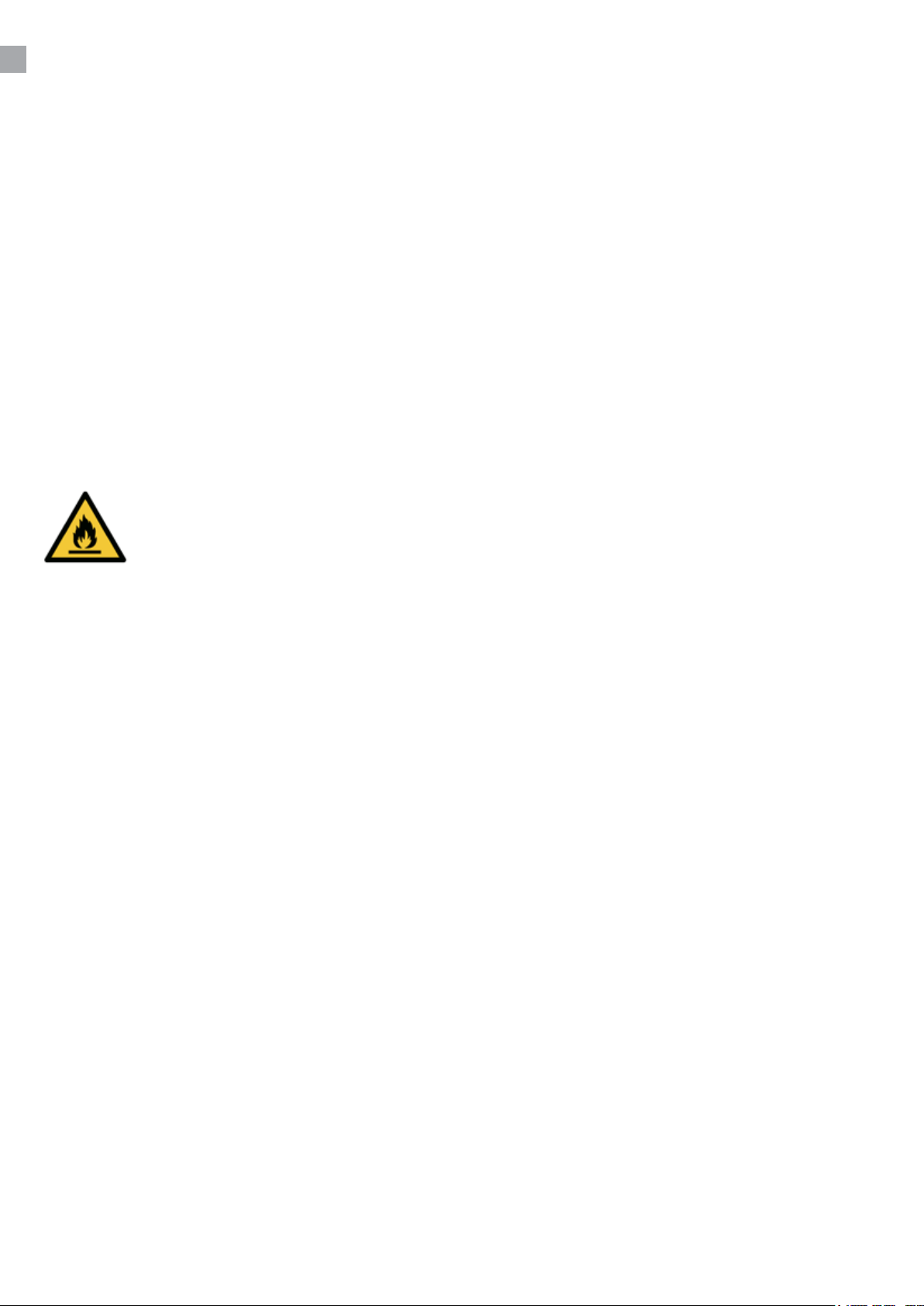
Der Kühlschrank enthält das energieeziente und nicht ozonabbauende Kältemittel
R600a/R290. Weil R600a/R290 ein sehr brennbares Gas ist, muss unbedingt darauf
geachtet werden, dass der Kühlschrank im Transport und bei der Installation nicht
beschädigt wird. Wenn der Kühlschrank doch beschädigt wird, darf kein oenes Feuer
in der Nähe vom Schrank verwendet werden. In dem Fall darf der Schrank auch nicht
Strom zugeschlossen werden. Sorgen Sie außerdem für eine gute Entlüftung vom
Raum. Bei Zweifel kontaktieren Sie bitte sofort Ihren Lieferanten.
Wichtig!
Der Boden dieses Kühlgeräts ist für hermetisch verschlossene Behälter bestimmt, die verarbeitete
Lebensmittel enthalten (EN 16825).
AUFSTELLUNG
Der Schrank wird auf einer Holzpalette für sicheren Transport geliefert. Entfernen Sie diese und
stellen Sie den Schrank in einer geraden/waagrechten Position auf.
4
Page 5
ANSCHLIEβEN
Das Gerät hat eine Spannung von 220-240 V/50 Hz.
Der Stecker muss geerdet sein (Schuko).
Sollten Sie das Kabel ersetzen müssen, benutzen Sie unbedingt ein entsprechendes geerdetes
Kabel.
Bitte beachten Sie, dass der Anschluss lediglich durch einen erfahrenen Elektriker erfolgen darf.
Wenn der Kabel beschädigt ist sollte es bei entweder der Hersteller oder ein Service Vertreter ersetzt
werden um Gefahr zu vermeiden.
EINSCHALTEN
Es empehlt sich das Gerät vor Inbetriebnahme zu reinigen (Näheres unter „Reinigen“).
Wichtig!
Wenn der Schrank liegend geliefert ist, warten Sie 2 Stunden vor Einschalten.
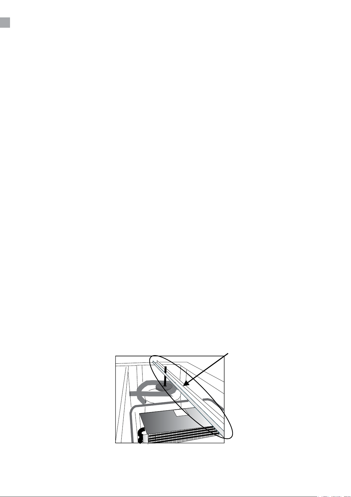
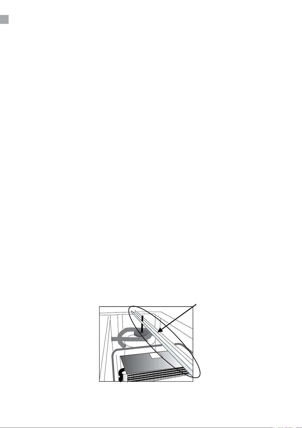
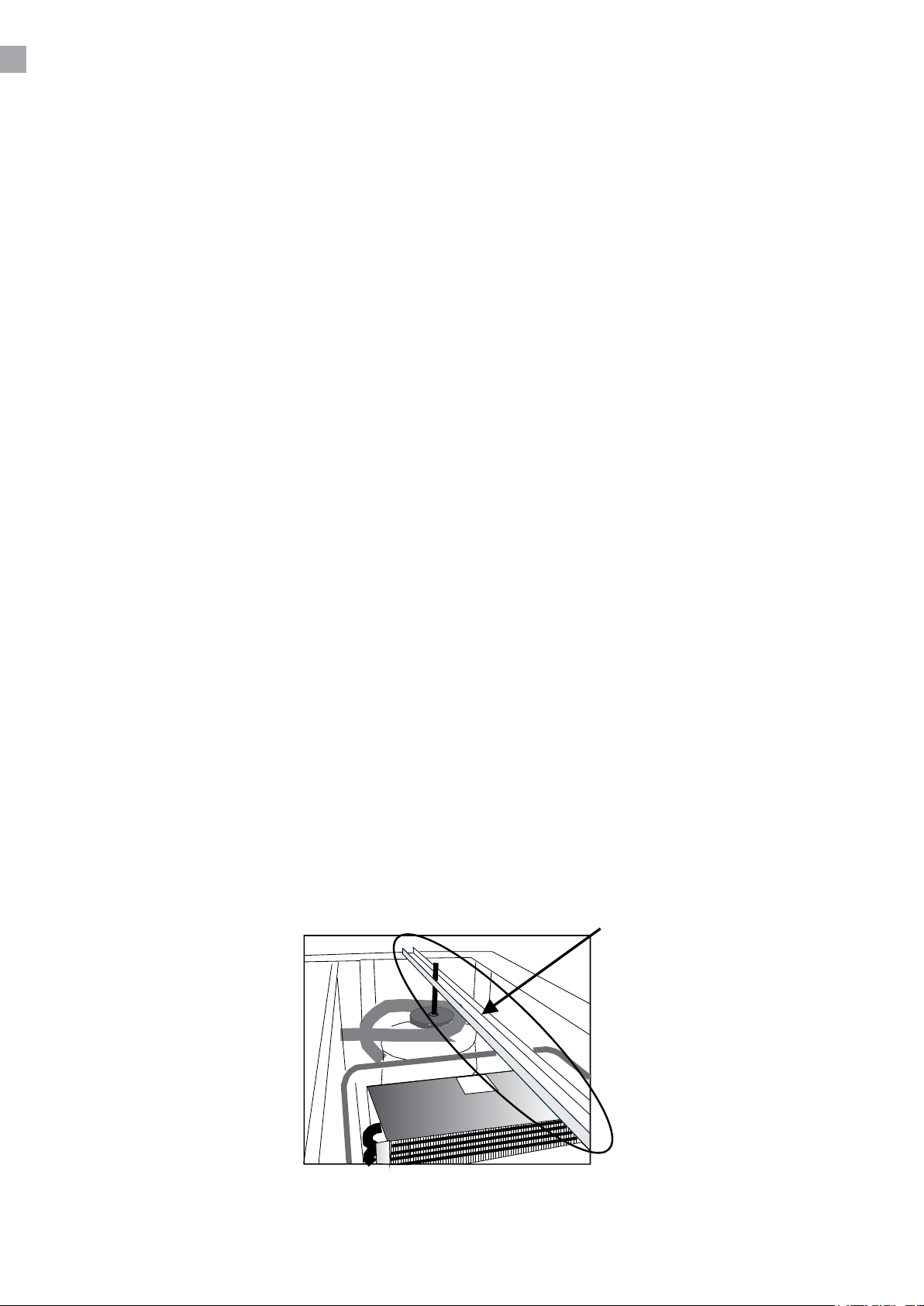
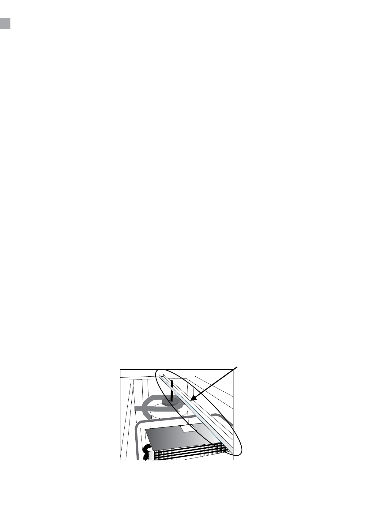
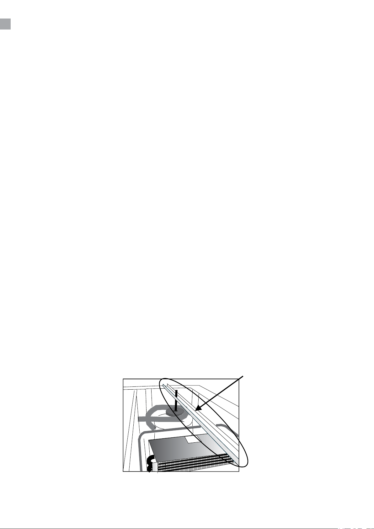
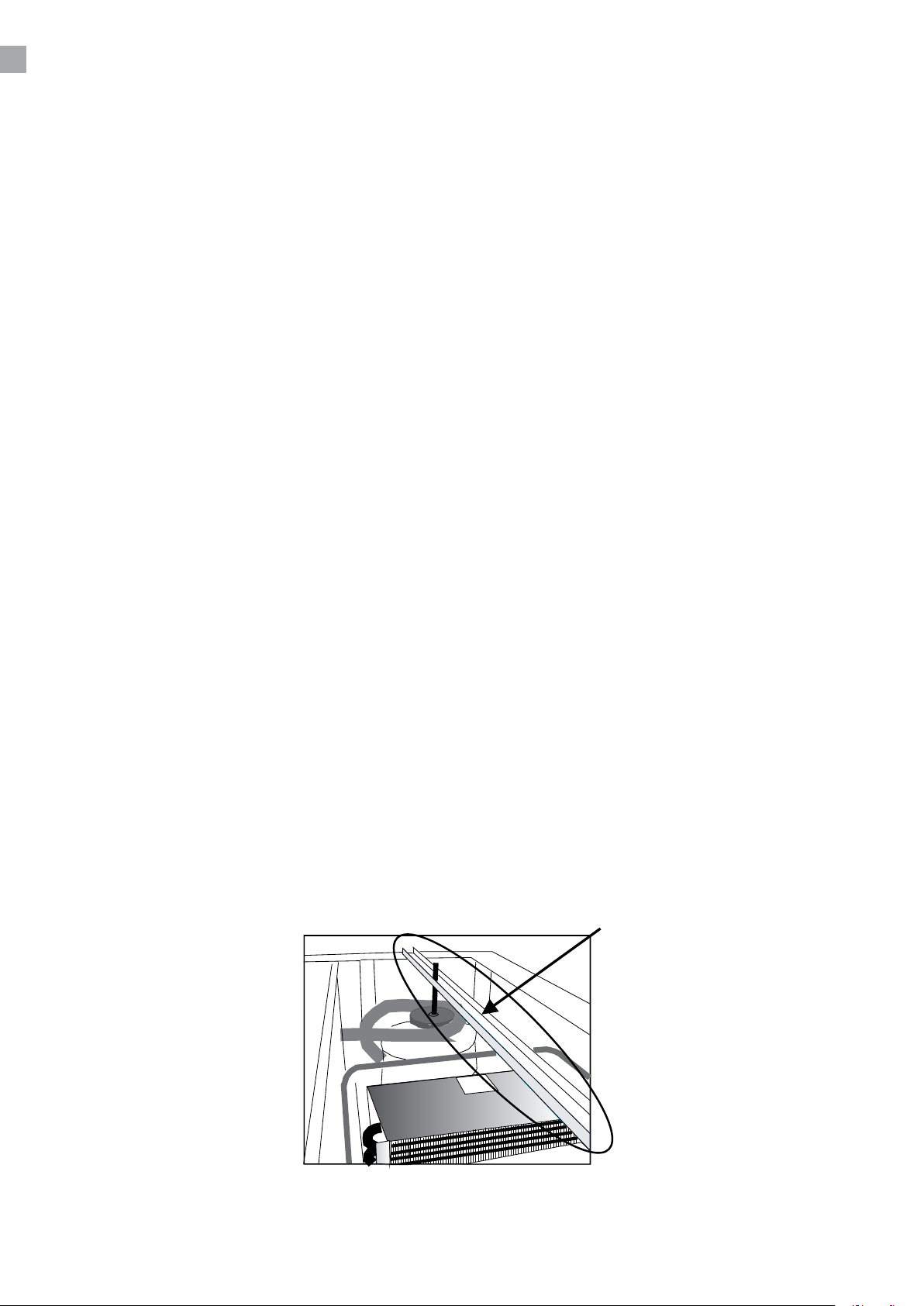
Bitte erinnern Sie die Transportsicherung auf dem Kompressor zu entfernen. Die ganze Stange
entfernen wie auf Figure:
5
Page 6
WECHSELN DES TÜRANSCHLAGES
Wichtig! Die Tür muss geschlossen werden, wenn der Türanschlag gewechselt wird!
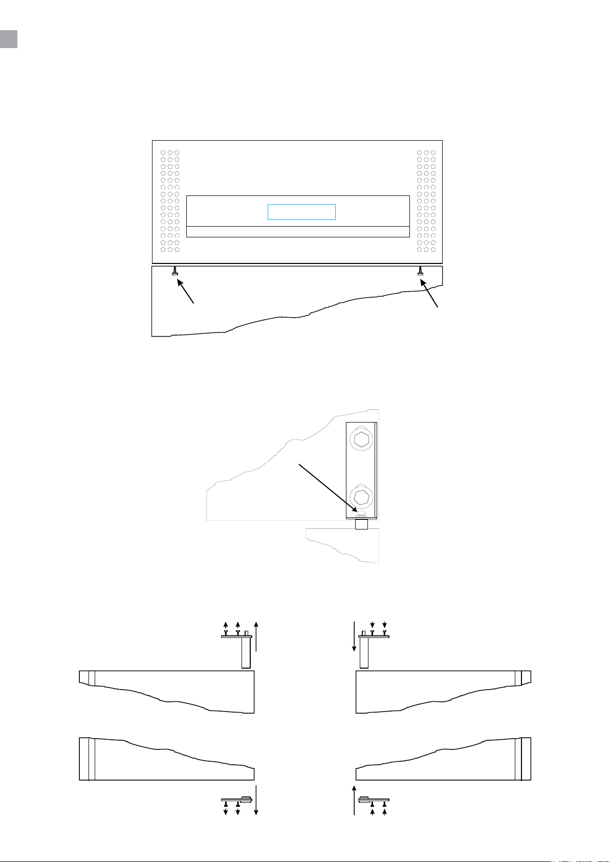
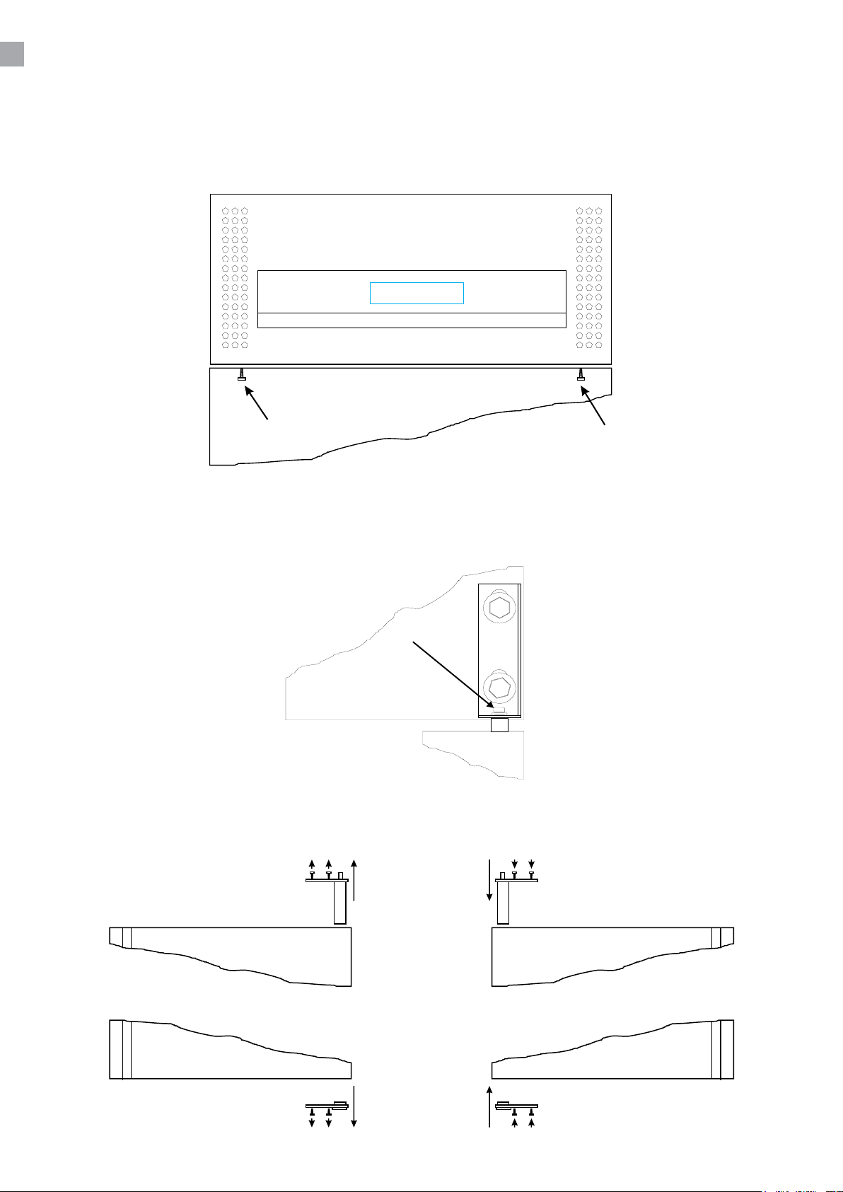
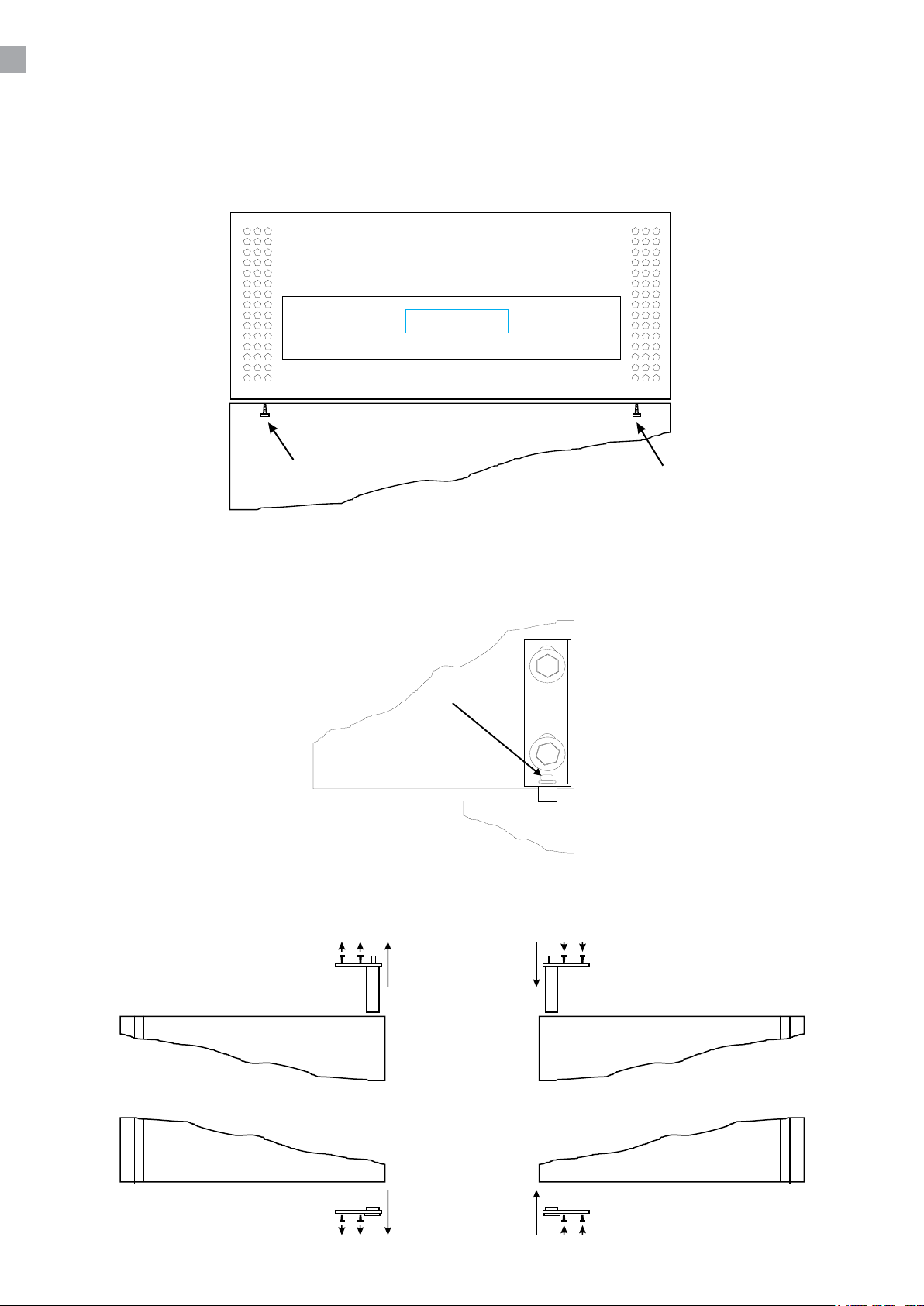
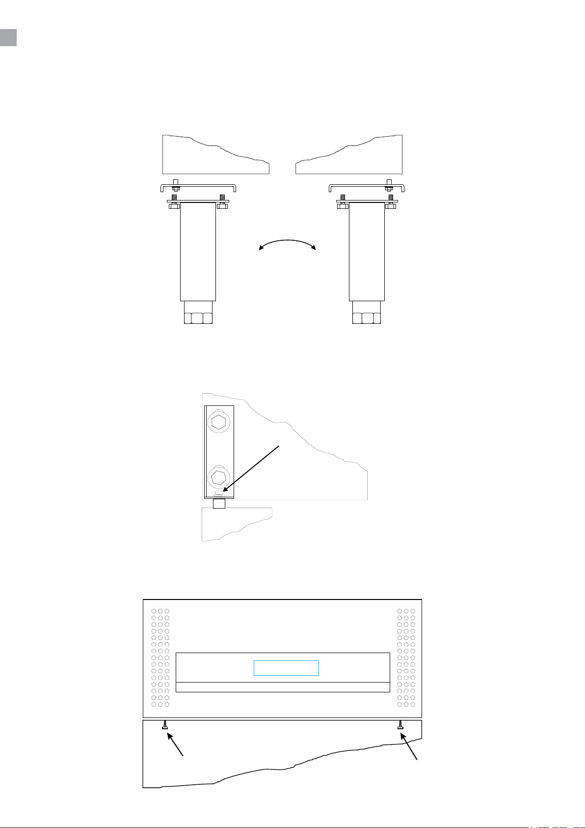
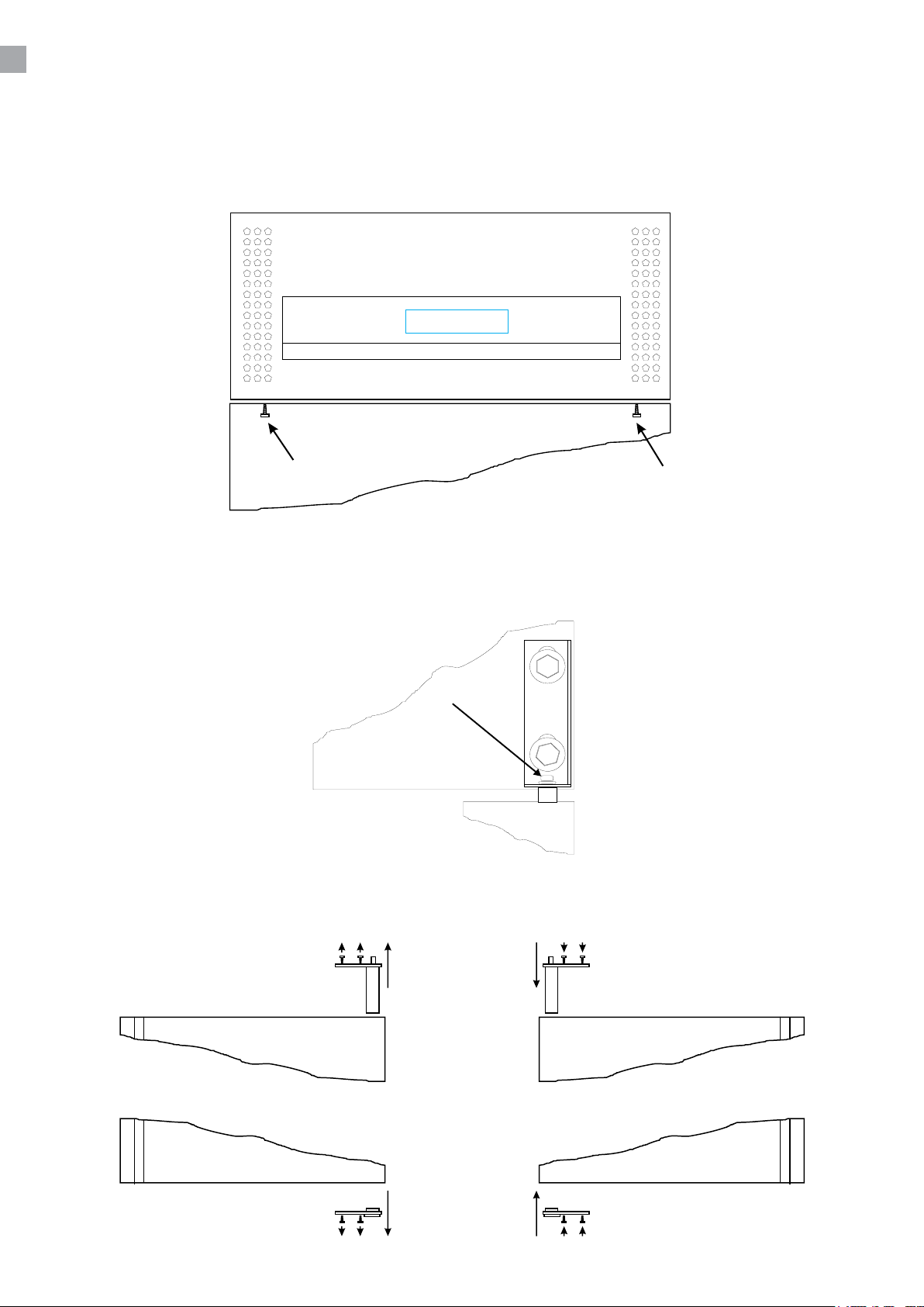
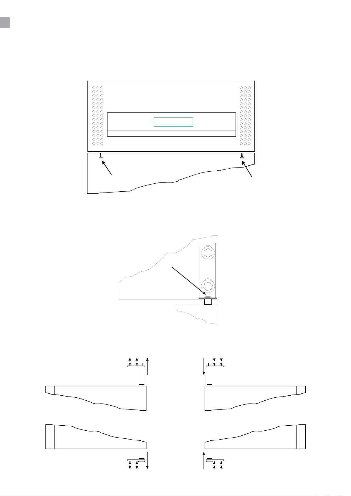
Önen Sie das Top um die in Fig. 1.2 markierte Schrauben zu entfernen.
Entfernen Sie die Schlossschraube in der Türfeder, wie in Fig. 1.3 markiert. Danach lösen sie das
Türscharnier und heben die Tür aus.
Legen Sie die Tür in der horizontaler Position und wechseln Sie die Türfeder und die Bodenbusche,
siehe Fig. 1.4.
6
Page 7
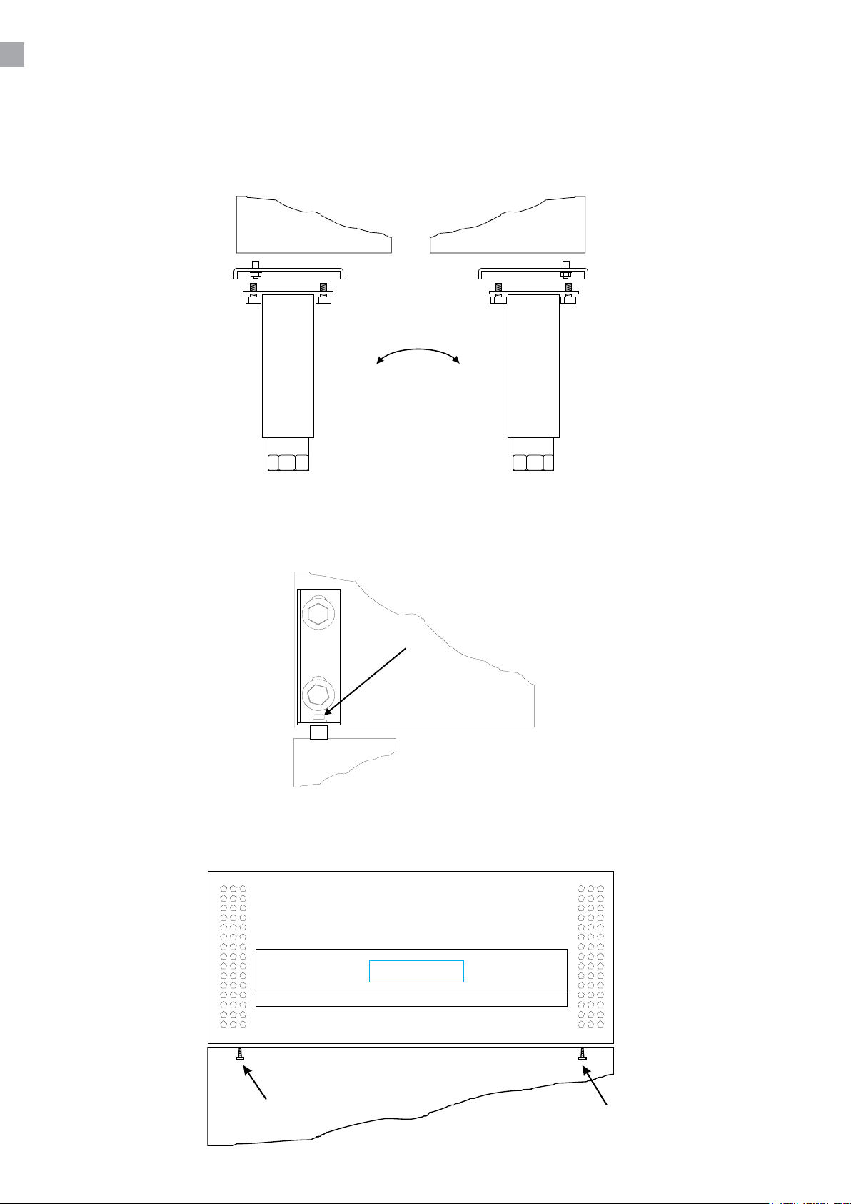
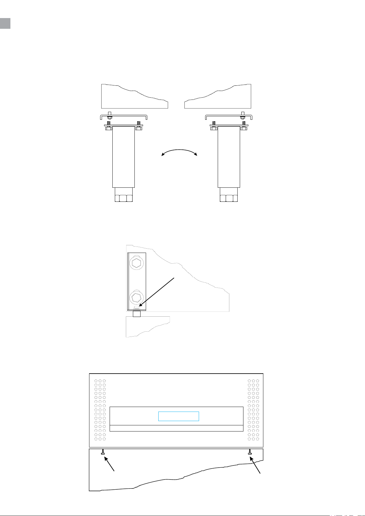
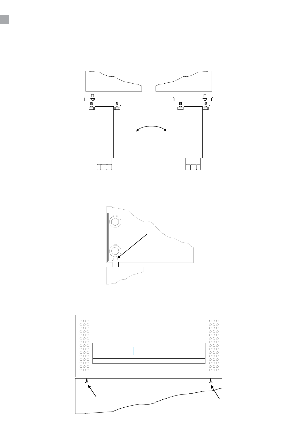
Um das Bodenscharnier zu wechseln muss man die vorne Stellschrauben/Rollen abmontieren und
danach das Scharnier in der anderen Seite montieren, siehe Fig. 1.5.
Lösen Sie das Obenscharnier in der neuen Scharnierseite und heben sie die Tür wieder auf das
Bodenscharnier auf. Drücken Sie das Scharnier auf der Türfeder und festmachen. Setzen Sie die
Schlossschraube ein (siehe Fig. 1.6).
Das Top zumachen und mit Schrauben festmachen. Siehe Fig. 1.7.
7
Page 8
TEMPERATURREGELUNG
Der Thermostat bendet sich in der oberen Blende.
Der Regler ist voreingestellt für den Schrank und normalerweise es ist nicht notwendig die
Einstellung zu regulieren.
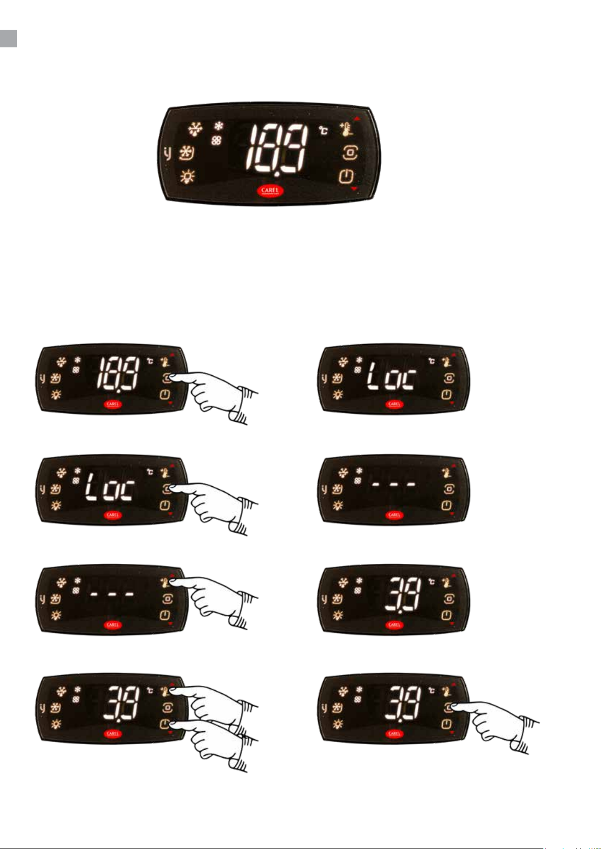
Bei Anschließen zeigt das Display die aktuelle Temperatur im Schrank.
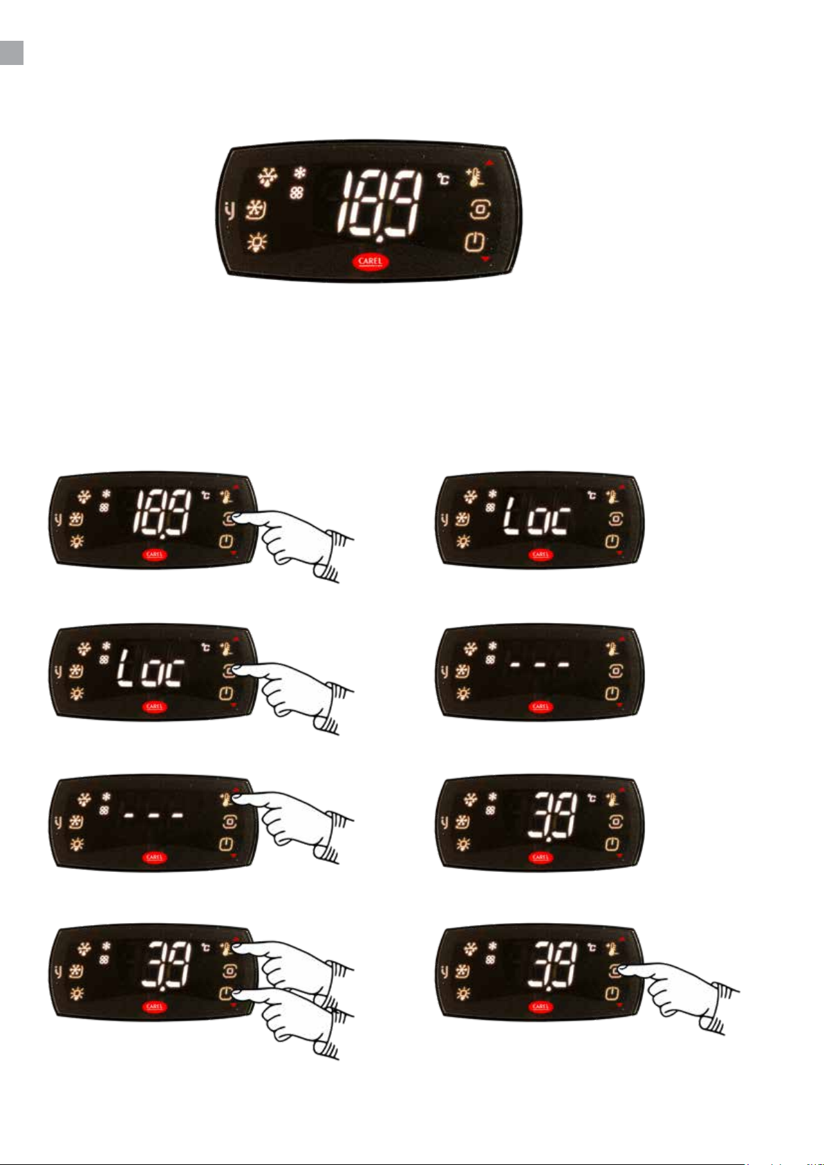
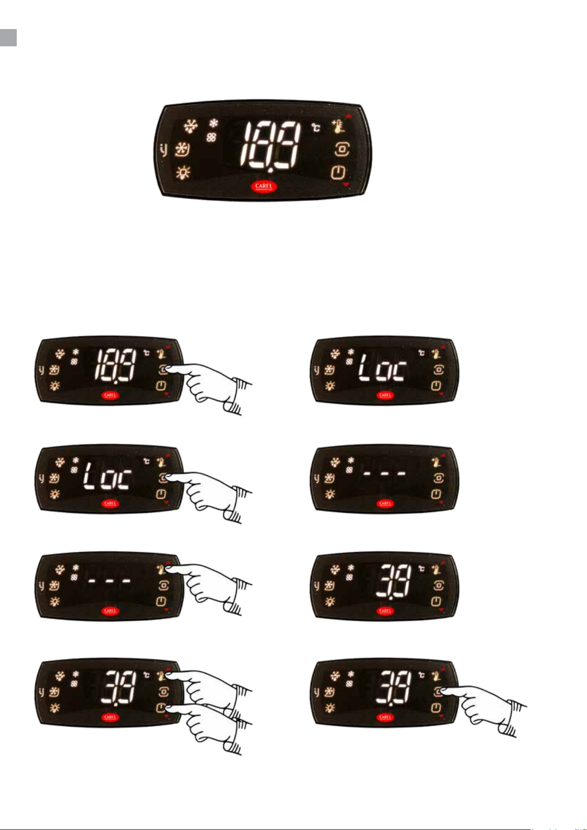
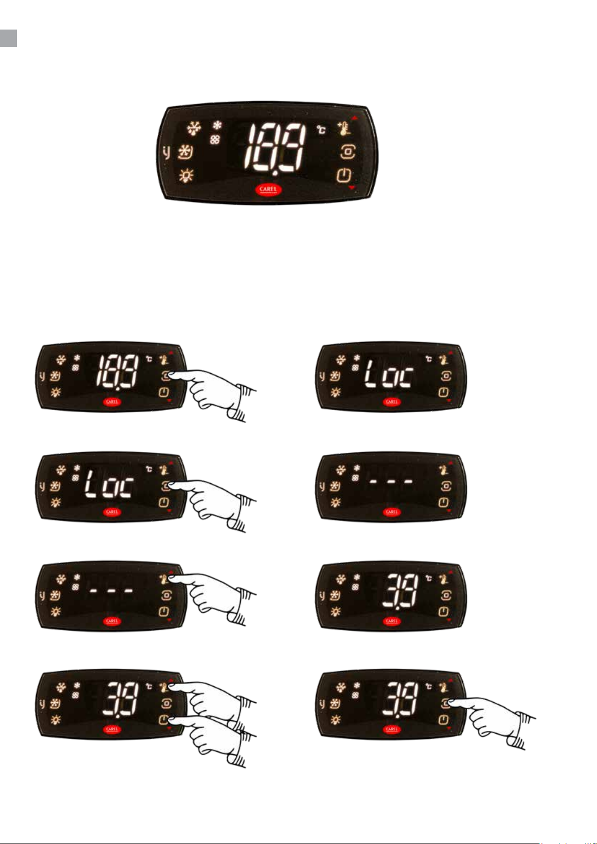
Neue Temperatur einstellen:
Drücken Sie die Taste PRG. Display zeigt:
Drücken Sie die PRG-Taste 3 Sekunden lang. Display zeigt:
Drücken Sie die SET-Taste. Display zeigt die eingestellt
Temperatur.
Mit den Auf-/Ab-Tasten ändern. Durch Drücken der PRG-Taste wird der neue
Wert gespeichert:
Page 9
ÄNDERUNG DER PARAMETER
Siehe Parameterübersicht vom Seite 11.
ABTAUEN
Der Schrank wird in vorprogrammierten Intervallen automatisch abgetaut. Falls der Schrank mit
häugen Önungen von Tür order häuge Auswechseln von Gefriergut äußerst belastet wird es ist
vielleicht notwendig der Schrank manuell abzutauen.
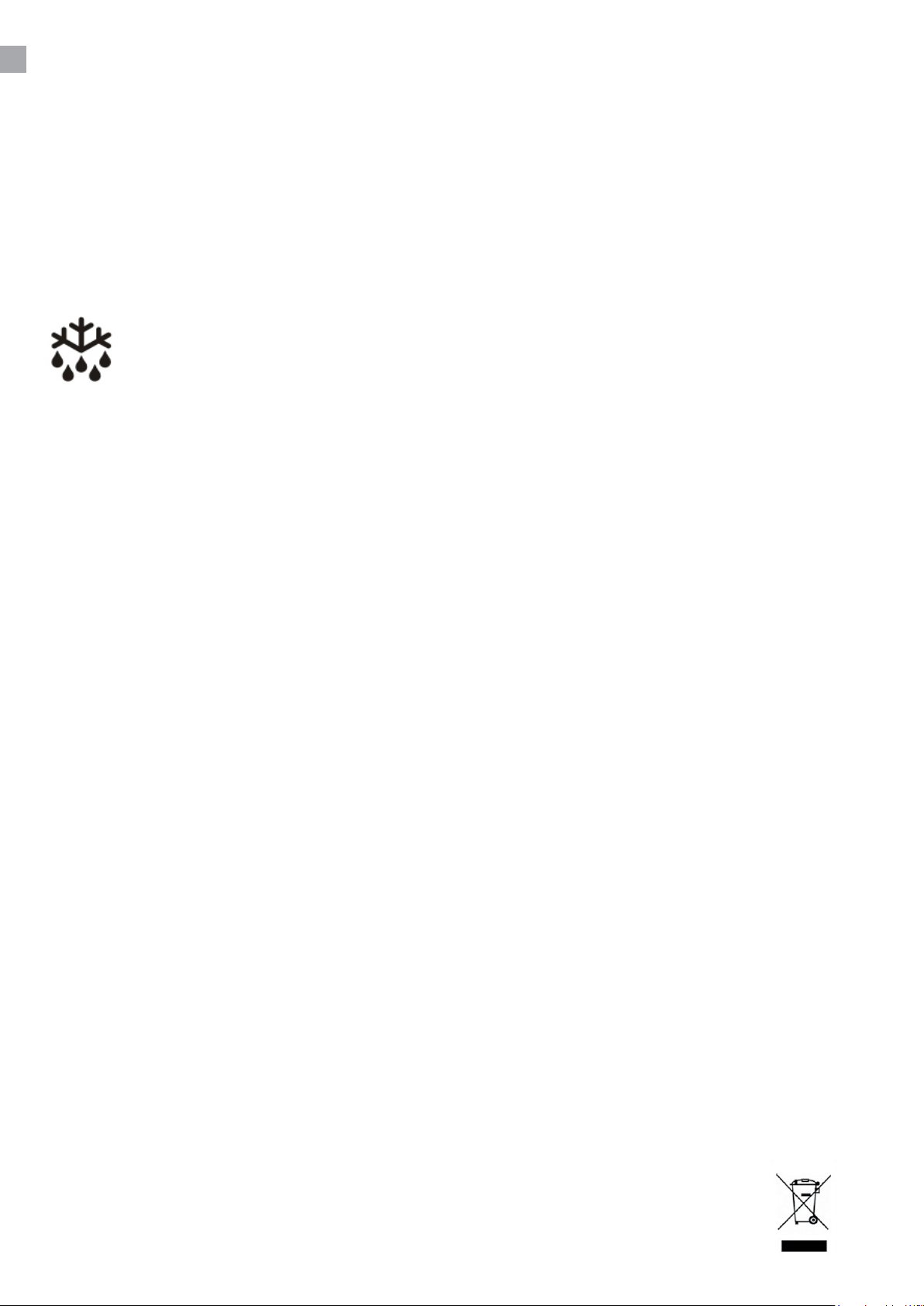
Drücken Sie auf diesen Taster mehr als 3 Sekunden fängt die manuellen Abtauung
statt, und dann zu normalen Betrieb zurückkehren.
Tauwasser zur Verdampfung wird in einen Behälter im Kompressorraum abgelassen.
REINIGUNG UND OPTIMIERUNG DER
ENERGIEEFFIZIENZ
Der Schrank auf Steckdose ausschalten.
In regelmäßigen Zwischenräumen den Schrank reinigen mit mildem Geschirrspülmittel innen und
außen. Alles mit einem Tuch gut trocken.
Verwenden Sie keine säurehaltige Putz- und chemische Lösungsmittel, diese möchten Rostfraß auf
die oberächen und Innenkühlsystem verursachen.
Kondensator und das übrige Kompressorraum mit Staubsauger reinigen und eine steife Bürste.
Achten Sie darauf, dass kein Wasser im Kompressorraum und in de elektrischen Teile kommt, das
Kurzschluss verursachen kann.
WARTUNG UND KUNDENDIENST
Das Kühlsystem ist ein hermetisches geschlossenes System und fordert kein Besichtigung nur
Reinigung.
Bei Ausfall der Kühlung prüfen Sie ob der Netzstecker richtig in der Stockdose ist und die Sicherung
der Stockdose in Ordnung ist.
Wenn keine Ursachen vorliegen und Sie die Störung nicht selbst beseitigen konnten, wenden Sie
sich bitte an die Kundendienststelle. Teilen Sie die Typenbezeichnung und Seriennummer mit. Diese
Informationen nden Sie auf den Typenschild in Schrank an der rechten Seite oben.
ENTSORGUNG
Wenn der Schrank ausgedient hat, muss die Entsorgung durch eine anständig umweltmäßige
Wiese vorgenommen werden. Beachten Sie die Vorschriften für Entsorgung. Es gibt z.B.
Spezialforderungen und Bedingungen zu beachten.
9
Page 10

Specications subject to changes without prior notication.
rfj_250311
TEFCOLD A/S, Industrivej 25, DK-8800 Viborg
© TEFCOLD A/S 2025
Page 11
Gastro-Line Køleskabe
Brugsvejledning
DK 3
Page 12

2
Page 13

INDHOLD
1.
2.
Brugsvejledning
Vigtige informationer og energi besparende anbefalinger ..................................... 4
Udpakning og opstilling .......................................................................................... 4
El-tilslutning ........................................................................................................... 5
Opstart ................................................................................................................... 5
Vending af dør ....................................................................................................... 6
Termostaten ........................................................................................................... 8
Afrimning ............................................................................................................... 9
Vedligeholdelse ...................................................................................................... 9
Service ................................................................................................................... 9
Bortskaelse ........................................................................................................... 9
Termostat Carel ijF
Teknisk manual .................................................................................................... 11
3
Page 14
VIGTIGE INFORMATIONER OG ENERGI
BESPARENDE ANBEFALINGER
1. For at få det fulde udbytte af kølemøblet, bør De læse denne brugsvejledning igennem.
2. Det er brugers ansvar at anvende kølemøblet i henhold til instruktionerne.
3. Kontakt omgående forhandleren, såfremt der opstår fejl ved kølemøblet.
4. Kølemøblet bør anbringes i et tørt og tilstrækkeligt ventileret rum.
5. Kølemøblet bør ikke placeres i nærheden af varmekilder eller direkte sollys.
6. Varme drikke og madvarer bør køles ned inden de placeres i kølemøblet.
7. Væsker bør opbevares i tildækkede beholdere for ikke at få luftfugtigheden til at stige i
kølemøblet og få køletiden til at forøges.
8. Åbnedøreogskuersåkortvarigtsommuligt.
9. Kontrollereatdøreogskuerlukkertætogrengørtætningslisternejævnligt.
10. Bemærk at alle elektriske apparater kan medføre farer.
11. Opbevarikkeeksplosionsfarligestoer,f.eks.gas,benzin,æteroglignende.
12. Der er ikke brugt asbest eller CFC i konstruktionen.
13. Olien i kompressoren indeholder ikke PCB.
Kølemøblet indeholder det energirigtige og ikke ozonnedbrydende kølemiddel R600a/
R290. Da R600a/R290 er en brandfarlig gasart, er det vigtigt, at kølekredsløbet ikke
beskadiges under transport og ved installering.
Hvis kølekredsløbet alligevel beskadiges, skal du undgå at bruge åben ild i nærheden
af køleskabet, ligesom der heller ikke må tilsluttes strøm til skabet. Sørg desuden for
god udluftning i rummet. Er du i tvivl, skal du kontakte din leverandør.
Vigtigt !
Bunden af dette kølemøbel er velegnet som opbevaringsareal af hermetisk lukkede beholdere med
forarbejdede fødevarer (EN 16825).
UDPAKNING OG OPSTILLING
Produktet leveres emballeret, undersøg denne for skader inden udpakning
4
Page 15
EL-TILSLUTNING
Kølemøblet er beregnet for tilslutning til 220-240 V/50 Hz. Tilslutningen skal ske ved en stikkontakt,
der bør være let tilgængelig.
Dette kølemøbel skal ekstrabeskyttes ifølge stærkstrømsreglementet. Dette gælder også, selvom der
er tale om udskiftning af et eksisterende kølemøbel, der ikke har været ekstrabeskyttet. I bygninger
opført før 1. april 1975 er ekstrabeskyttelsen i orden, hvis der er installeret HFI-afbryder, som
beskytter den stikkontakt kølemøblet skal tilsluttes.
I begge disse tilfælde skal der, hvis stikkontakten er for trebenet stikprop, benyttes en trebenet
stikprop, og lederen med grøn/gul isolation skal tilsluttes jordklemmen (mærket ).
Hvis stikkontakten kun er for tobenet stikprop, benyttes en tobenet stikprop. Hvis brugeren selv
monterer denne, skal lederen med grøn/gul isolation klippes af så tæt som muligt på det sted, hvor
lederen går ind i stikproppen.
I alle andre tilfælde bør De lade en autoriseret el-installatør undersøge, hvordan De nemmest får
ekstrabeskyttet kølemøblet. Hvis De ikke har ekstrabeskyttelse i bygningen i forvejen, anbefaler
Elektricitetsrådet, at De lader el-installatøren opsætte en PFI- eller HPFI afbryder.
OPSTART
Inden kølemøblet tages i brug, anbefales det at rengøre dette, se afsnit om vedligeholdelse.
Vigtigt !
Hvis kølemøblet har ligget ned under transport, vent 2 timer før opstart.
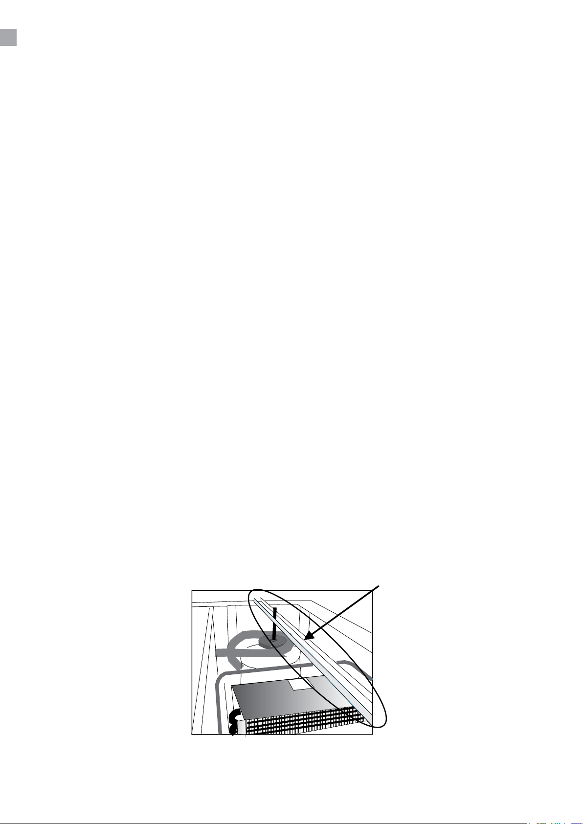
Huskatfjernetransportsikringpåkompressor,fjernhelestangensomvistig.1.8.
5
Page 16
VENDING AF DØR
HUSK dette skal foretages når døren er åben !
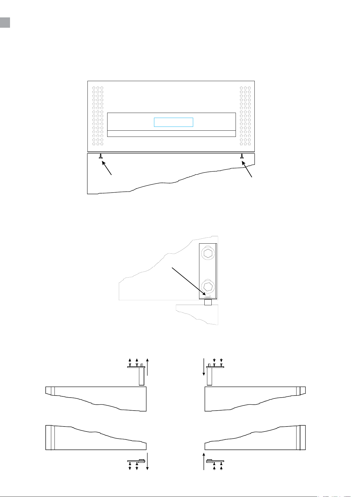
Åbentoppenvedatfjernemarkeredeskruerig.1.2.
Fjernlåseskrueidørfjeder,markeretig.1.3,hængsletløsnesogdørenløftesaf.
Dørenliggesnedhvorefterdørfjederenogbund-bøsningenombyttes,seg.1.4.
6
Page 17
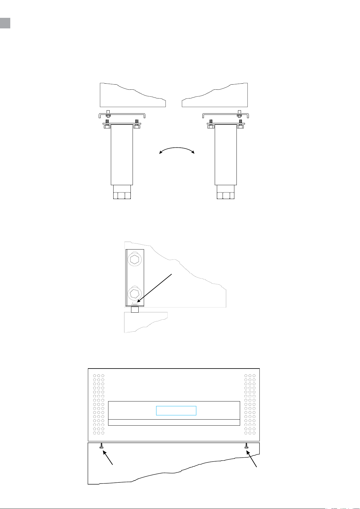
Bundhængselyttesvedatafmonteredeforresteben/hjulogdereftermontereimodsatteside,se
g.1.5.
Tophængsel i ny hængselside løsnes og døren løftes på plads på bundhængsel. Hængsel trykkes
nedpådørfjederogfastgøres.Isætlåseskrueseg.1.6.
Lukogfastgørtopmedskruerseg.1.7.
7
Page 18
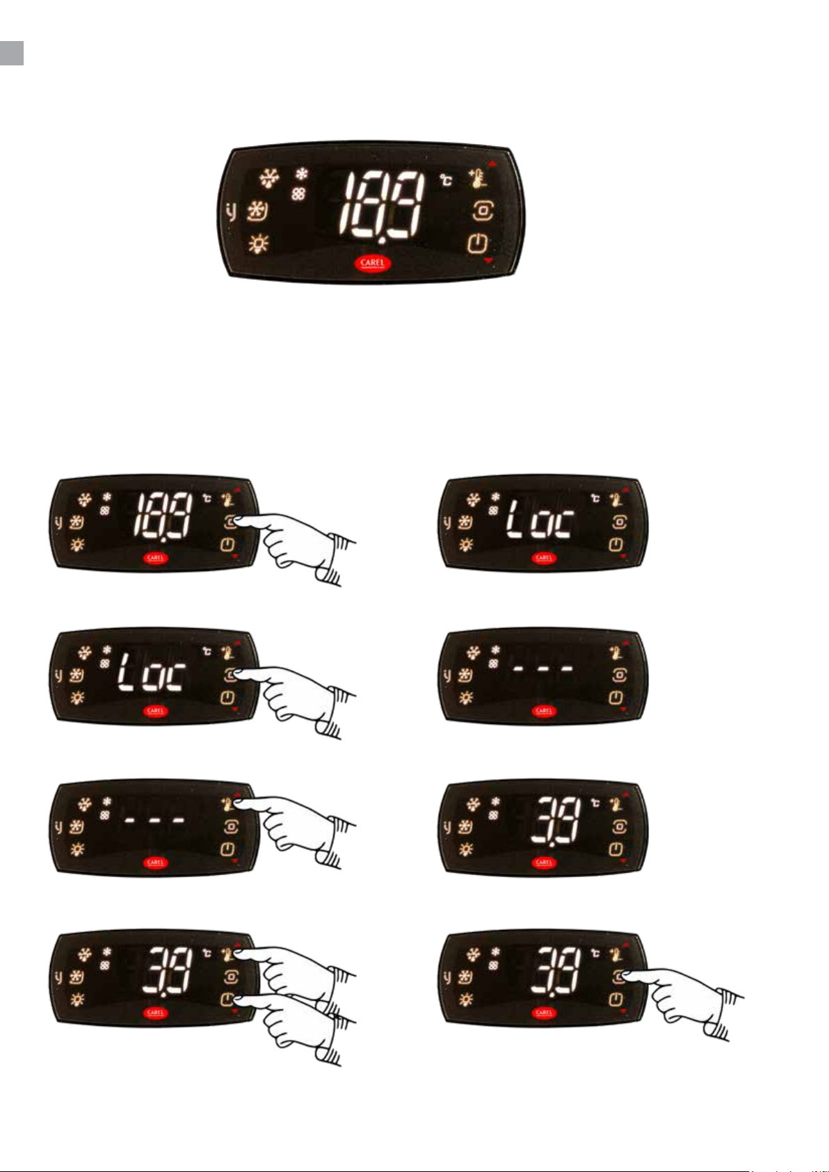
TERMOSTATEN
Termostaten er placeret i top panelet
Termostaten er for-programmeret så kølemøblet er klar til brug. Hvis der skal justeres i indstillinger
følg denne vejledning.
Når skabet tændes vil display vise den aktuelle temperatur i møblet.
Indstil ny temperatur:
Tryk på Prg-tasten. Display viser:
Tryk på Prg-tasten i mere end 3 sekunder. Display viser:
Tryk på Set-tasten. Display viser Set temperaturen:
Brug Pil-tasterne for at justere. Tryk på Prg-tasten for at gemme den nye
temperatur:
Page 19
ÆNDRING AF PARAMETRE
Se parameter oversigt og manualer fra side 11.
AFRIMNING
Kølemøblet afrimer automatisk med forprogrammerede intervaller. Hvis møblet belastes ekstremt
med hyppige åbninger af dør eller hyppig udskiftning af varer, kan det blive nødvendigt at udføre en
manuel afrimning.
Tryk på denne tast i mere end 3 sec., dette vil starte en manuel afrimning og derefter
vende tilbage til normal drift.
Tøvand ledes ud til fordampning i en beholder, der er placeret i kompressorrum.
VEDLIGEHOLDELSE
Afbryd kølemøblet på stikkontakten.
Med passende mellemrum skal kølemøblet rengøres. Udvendig og indvendige rengøring foretages
med svag sæbeopløsning og aftørres grundigt
.
Rengøringsmidler må IKKE indeholde klor, klorforbindelser eller andre aggresive midler, da de kan
forårsagetæringerpåoveraderogpådetindvendigekølesystem.
Ventilationsristen holdes bedst rent ved hjælp af en støvsuger og en stiv børste.
SERVICE
Kølesystemet er et hermetisk lukket system og kræver ikke tilsyn, kun renholdelse.
Ved svigt i kølevirkningen, undersøg om årsagen er afbrydelse i stikkontakt eller sikringsgruppe.
Kangrundentilsvigtikkendes,måDehenvendeDemtilDeresleverandør.Vedalhenvendelse
bedesDeoplyseskabetstypenavnogserienummer.Disseoplysningerndespåtypenummerskiltet
placeret indvendigt i højre side.
BORTSKAFFELSE
Nårdetudtjentekølemøbelskalbortskaes,skaldetskepåenmiljømæssigforsvarligmåde.Vær
opmærksompåreglerneforbortskaelse.Derkanværesærligekravogbetingelser,derskal
overholdes.
9
Page 20

Specications subject to changes without prior notication.
rfj_250311
TEFCOLD A/S, Industrivej 25, DK-8800 Viborg
© TEFCOLD A/S 2025
Page 21
Gastro-Line Mesas frías
Manual del usuario
ES 3
Page 22

2
Page 23

SOMMARIO
1.
2.
Información general
Importantes instrucciones de seguridad ................................................................ 4
Desembalaje e instalación...................................................................................... 4
Conexión eléctrica .................................................................................................. 5
Puesta en marcha del aparato ............................................................................... 5
Cambio de la puerta .............................................................................................. 6
Termostato ............................................................................................................. 8
Descongelación. .................................................................................................... 9
Mantenimiento y optimización de la eciencia energética.................................... 9
Servicio técnico ...................................................................................................... 9
Como deshacerse del aparato .............................................................................. 9
Termostato Carel ijF
Manual técnico para el termostato ....................................................................... 11
3
Page 24
IMPORTANTES INSTRUCCIONES DE SEGURIDAD
1. Para obtener el uso completo y adecuado del aparato, recomendamos leer este manual de
instrucciones.
2. Es responsabilidad del usuario el manejo adecuado del aparato, de acuerdo con las
instrucciones dadas.
3. Contacte a su comerciante inmediatamente en caso de cualquier funcionamiento defectuoso.
4. Coloque el aparato en un lugar seco y ventilado.
5. Mantenga el aparato totalmente alejado de cualquier fuente de calor y no lo exponga a la luz
directa del sol.
6. Tenga siempre presente que todo dispositivo eléctrico es una fuente potencial de peligro.
7. No almacene material inammable tal como gas, gasolina, éter ó similares en el aparato.
8. No ha sido utilizado ningún asbesto ni CFC en la construcción.
9. El aceite en el compresor no contiene TCI.
¡SOLO PARA LOS MODELOS QUE INCORPOREN REFRIGERANTE R290/R600a!
Este electrodoméstico contiene un refrigerante inamable. Por lo tanto, asegúrese de
disponer de una buena ventilación a su alrededor. No utilice dispositivos mecánicos
para descongelar el electrodoméstico, ya que podría causar fugas en el sistema
de refrigeración.No utilice aparatos eléctricos en el interior del compartimento de
almacenamiento refrigerado.
Deje cualquier reparación del electrodoméstico en manos de un técnico cualicado
(EN 60335-2-89: 2010).
Importante !
La base de este refrigerador está diseñada para recipientes herméticamente sellados que
contienen alimentos procesados (EN 16825).
DESEMBALAJE E INSTALACIÓN
El aparato se entrega embalado y en un palet, desembálelo. Las supercies exteriores están
forradas con un plástico protector, quítelo antes de hacer la instalación.
4
Page 25
CONEXIÓN ELÉCTRICA
Este electrodoméstico está diseñado para su uso a 230 V/50 Hz. Debe enchufarse a una toma de
corriente accesible.
Este electrodoméstico debe disponer de una protección adicional de acuerdo con las normativas
sobre electricidad. Esto es aplicable también en el caso de que reemplace una unidad existente que
no disponga de protección adicional.
Use siempre un enchufe de tres clavijas. El hilo con aislante verde/amarillo debe conectarse a tierra
(con marca ).
En todos los demás casos, un electricista autorizado le informará sobre cómo obtener la protección
adicional para el electrodoméstico. En caso de el edicio no disponga de protección adicional, las
autoridades recomiendan que un electricista instale un interruptor PFI o HPFI (disyuntor).
PUESTA EN MARCHA DEL APARATO
Antes de su uso, recomendamos que el aparato se limpie, vea la sección de mantenimiento y
limpieza
Importante !
Si el aparato ha sido colocado horizontalmente durante su transporte, espere, por favor, 2 horas
antes de la puesta en marcha del aparato.
Recuerde quitar el dispositivo de seguridad de transporte en el compresor. Quite la barra entera,
como se muestra en g. 1.8.
5
Page 26
CAMBIO DE LA PUERTA
Recuerde, que se debe hacer con la puerta abierta.
Abra la parte alta quitando los tornillos mostrados en Fig. 1,2.
Quite la contratuerca del resorte de la puerta, como se muestra en Fig. 1,3. Aoje la bisagra y quite
la puerta.
La puerta se coloca horizontalmente abajo, y después se pasa a invertir el resorte de la puerta y el
casquillo/manguito del fondo, ver Fig. 1.4.
6
Page 27
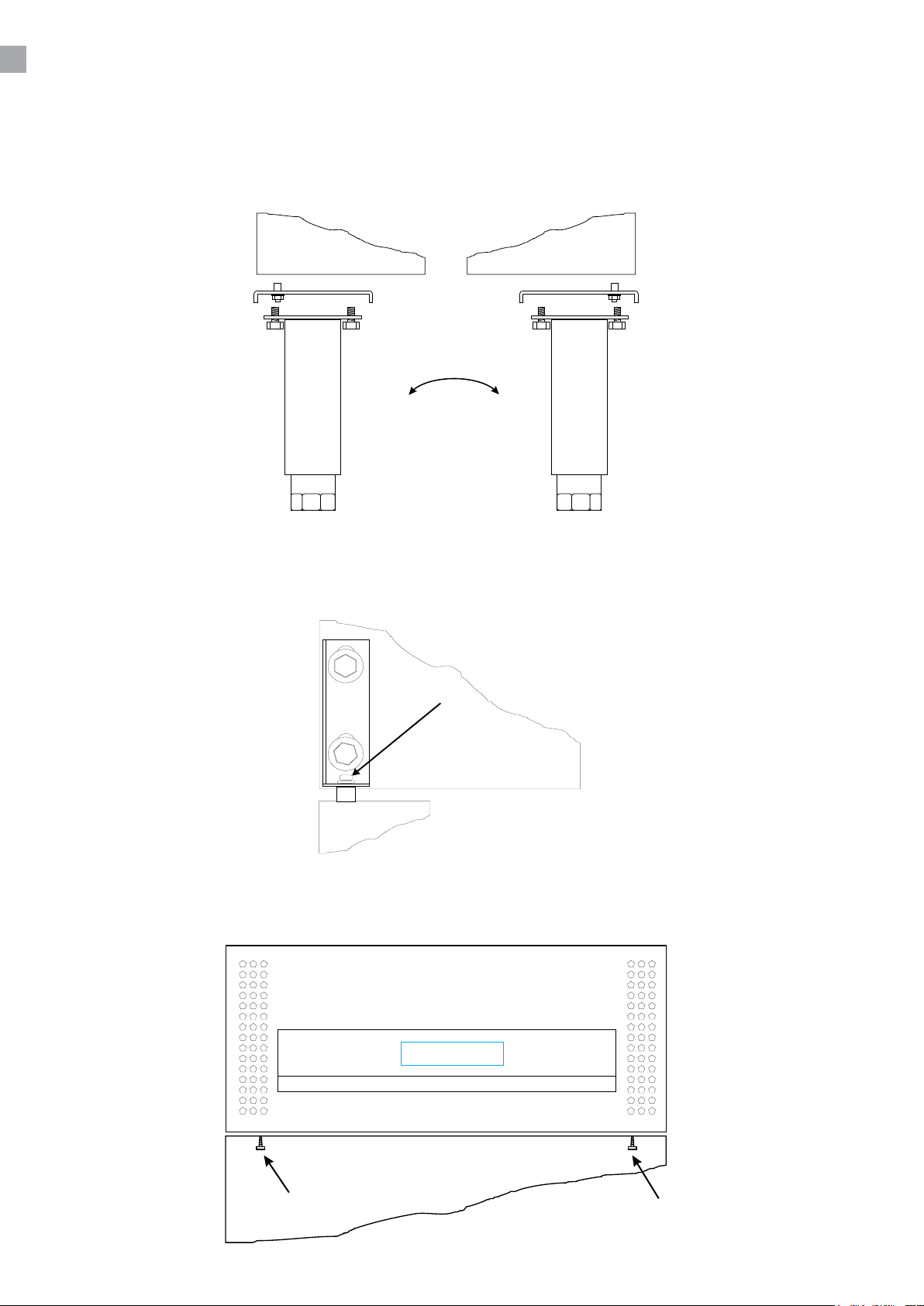
La bisagra inferior es invertida desmontando las patas/las ruedas delanteras, y después las monta
en el otro lado del aparato, ver Fig. 1.5.
En el lado de la nueva visagra, aoje la visagra de arriba, y coloque la puerta en la visagra de abajo.
La visagra se ajusta/aprieta en el resorte de la puerta para que se quede ja. Coloque la
contrapuerca, como en Fig. 1.6
Cierre y je la parte superior con los tornillos ver Fig. 1.7.
7
Page 28
TERMOSTATO
El termostato está colocado en el tablero de control.
El termostato ya está programado para este aparato. En la mayoria de los casos, no es necesario
ajustar las posiciones.
Al encender el aparato, el display/pantalla mostrará la temperatura actual en el aparato.
Cambio a nueva temperatura:
Presione la tecla Prg. La pantalla mostrará:
Presione la tecla Prg durante más de 3 segundos. La pantalla mostrará:
Presione la tecla Set. La pantalla mostrará la temperatura
establecida:
Utilice las teclas Arriba/Abajo para cambiar. Utilice la tecla Prg para guardar la temperatura
establecida:
Page 29
CAMBIO DE PARÁMETROS
Vea lista de parámetros en la página 11.
DESCONGELACIÓN
El aparato descongela automáticamente con intervalos jos programados. Si la puerta del aparato
está abierta o el contenido del aparato se cambia con frecuencia, puede llegar a ser necesario
descongelar el aparato manualmente.
Apriete esta tecla continuamente, más de 3 segundos, esto activará una
descongelación manual, y después volverá a operar normalmente.
El agua de la descongelación circula para su evaporación a un contenedor, que está situado en el
compartimento del compresor.
MANTENIMIENTO Y OPTIMIZACIÓN DE LA EFICIENCIA
ENERGÉTICA
Apague el aparato desde el enchufe.
El aparato debe ser limpiado periódicamente. Limpie las supercies externas e internas del aparato
con una solución ligera de jabón, y seque bien. Las supercies externas pueden mantenerse limpias
con un aceite especial para acero.
No utilice limpiadores que contienen cloro u otros productos agresivos, pues pueden dañar las
supercies inoxidables del acero y el sistema interior de refrigeración.
Limpie el condensador y el compartimento del compresor con la ayuda de un aspirador y un cepillo
duro.
No riegue con una manguera el compartimento del compresor, ya que el agua puede causar
cortocircuitos y daño en las partes eléctricas.
SERVICIO TÉCNICO
El sistema de refrigeración es un sistema herméticamente sellado, y no requiere supervisión, sólo
limpieza.
Si el aparato falla en la refrigeración, verique que la razón no sea un apagón, bien desde el enchufe
o de los plomos.
Si no puede localizar la razón del fallo del aparato, contacte, por favor, a su suministrador.
Informe, por favor, del modelo y el número de serie del aparato.Usted puede encontrar esta
información en la etiqueta que está colocada dentro del aparato arriba, a mano derecha.
COMO DESHACERSE DEL APARATO
Cuando se tenga que deshacer del aparato, deberá hacerlo teniendo en cuenta las normas al
respecto. Puede que haya unas exigencias y condiciones que se deban cumplir.
9
Page 30

Specications subject to changes without prior notication.
rfj_250311
TEFCOLD A/S, Industrivej 25, DK-8800 Viborg
© TEFCOLD A/S 2025
Page 31
Gastro-Line Comptoirs
Mode d’ emploi
FR 3
Page 32

2
Page 33

SOMMAIRE
1.
2.
Users manual
Informations générales .......................................................................................... 4
Désassemblage et mise en place .......................................................................... 4
Branchement électrique ......................................................................................... 5
Démarrage.............................................................................................................. 5
Inversement de la porte .......................................................................................... 6
Thermostat ............................................................................................................ 8
Dégivrage .............................................................................................................. 9
Maintenance et optimisation de l’ecacité énergétique ........................................ 9
Service ................................................................................................................... 9
Élimination .............................................................................................................. 9
Thermostat Carel ijF
Manuel technique du thermostat ......................................................................... 11
3
Page 34
INSTRUCTIONS IMPORTANTES
1. Avant d’utiliser votre armoire, nous vous recommandons de lire ce mode d’emploi dans son
entier.
2. C’est la responsabilité de l’utilisateur de manier l’appareil selon les instructions données.
3. Contacter votre revendeur immédiatement en cas de défauts de fonctionnement de l’armoire.
4. L’armoire doit être placée dans un endroit sec et ventilé.
5. L’armoire ne doit pas être exposée aux rayons du soleil ou à tout autre source de chaleur.
6. N’oublier pas que tous les appareils électriques sont des sources de danger potentiel.
7. Ne conserver pas et n’utilisez pas des produits qui pourraient provoquer des explosions ou qui
sont inammables, tels que gaz, briquets, essence, éther etc. dans l’armoire.
8. Aucune asbeste ou CFC est utilisée dans la construction de l’armoire.
9. L’huile dans le compresseur ne contient pas de PCB.
POUR LES ARMOIRES AVEC RÉFRIGÉRANT R290/R600a!
Ce refroissseur contient un réfrigérant inammable; assurez un endroit bien ventilé
autour de l’armoire. N’utilisez pas des outils mécaniques pour le dégivrage; cela peut
causer des fuites dans le système de refroidissement interne. N’utilisez pas des outils
électrique á l’intérieur de l’armoire.
Chaque réparation de ce réfroidisseur doit être eectué par un réparateur professionel.
(EN 60335-2-89: 2010)
Important !
La base de ce réfrigérateur est conçue pour les récipients hermétiques contenant des aliments
transformés (EN 16825).
DÉSASSEMBLAGE ET MISE EN PLACE
L’armoire est livrée avec une palette en bois an de l’assurer pendant le transport. Enlever la palette
et placer l’armoire d’une position verticale. Les surfaces extérieures sont équippées d’un lm pelable,
qu’il faut enlever avant la mise en place.
Lors de la mise en place, l’armoire doit être de niveau, ce qui s’obtient aisément grâce aux pieds
réglables. (Quelques armoires sont livrées avec roulettes au lieu de pieds réglables).
4
Page 35
BRANCHEMENT ÉLECTRIQUE
L’armoire doit être branchée par une prise d’un accès facile avec la tension de 230 V/50 Hz.
Les installations électriques doivent être eectués par un électricien spécialisé.
DÉMARRAGE
Avant d’utiliser votre armoire, nous vous recommandons de la nettoyer, voir la section « entretien ».
Important !
Si l’armoire a été transportée aux horizontal, il faut attendre 2 heures après l’installation pour
démarrer l’appareil.
N’oublier pas d’enlever la protection du compresseur ; enlever le bâton entier (gure 1.8)..
5
Page 36
INVERSEMENT DE LA PORTE
N’oublier pas de fermer la porte avant de l’inverser.
Ouvrir le dessus de l’armoire en demontant les vis (gure 1.2).
Demonter le vis de blocage dans le ressort de la porte (gure 1.3), la charnière s’est lâchée et vous
pouvez demonter la porte.
Mettre la porte aux horizontal. Échanger le ressort de la porte et la boîte de fond (gure 1.4).
6
Page 37
La charnière de fond est déplacée en demontant les pieds/roulettes de devant, et puis les monter au
côté opposé (gure 1.5).
Lâcher la charnière dessus au nouveau côté charnière et monter la porte sur la charnière de fond.
Presser la charnière sur le ressort de la porte et xer-là. Monter le vis de blocage (gure 1.6)
Fermer et xer le dessus avec les vis (gure 1.7).
7
Page 38
THERMOSTAT
Le thermostat est placé dans le panneau de contrôle .
Il est préprogrammé pour l’armoire ; dans la plupart des cas il est donc inutile de le régler.
Quand l’armoire est allumée, l’acheur va montrer la température actuelle à l’intérieur de l’armoire.
Régler la nouvelle température:
Appuyez sur la touche Prg. L’écran achera :
Appuyez sur la touche Prg pendant. L’écran achera :
plus de 3 secondes.
Appuyez sur la touche Set. L’écran achera la température réglée :
Utilisez les touches Haut/Bas pour modier. Utilisez la touche Prg pour enregistrer la
température réglée :
Page 39
CHANGEMENT DES PARAMÈTRES
Voir table des paramètres page 11.
DÉGIVRAGE
L’armoire se dégivre automatiquement avec des intervalles programmés. Si l’armoire est exposée
aux ouvertures de la porte ou remplacements des marchandises très fréquents, un dégivrage manuel
peut être nécessaire.
Presser ce bouton pendant plus de 3 secondes ; cela va lancer un dégivrage manuel et
après retourner au fonctionnement normal.
L’eau de dégivrage est évacuée et s’évapore dans un récipient placé dans le compartiment
compresseur.
ENTRETIEN
Débrancher l’armoire pendant le nettoyage.
Le nettoyage de l’intérieur et l’extérieur de l’armoire doit être eectué par intervalles convenables
à l’aide d’un produit à vaisselle non parfumé. L’armoire doit être essuyée minutieusement après le
nettoyage. L’extérieur peut être maintenu avec un produit (creme, huile) pour l’inox.
N’utiliser pas des produits à vaisselle chlorés ou d’autres produits aggrésifs, parce qu’ils pourraient
causer la corrosion de l’acier inox et du système frigorique interne.
SERVICE
Le système frigorique est étanche à l’air ; il n’est donc pas nécesssaire de le surveiller, il sut de le
nettoyer.
Si l’armoire ne rafraîchit pas, vérier que la che est bien enfoncée, que la fusible est intact et qu’il
n’y a pas de coupure de courant.
Si vous ne pouvez pas trouver la cause du défaut, contacter votre revendeur. Informer la référence
et le numéro de série de l’armoire, ce que vous pouvez trouver à l’intérieur de l’armoire sur l’étiquette
placée en haut à droite.
ÉLIMINATION
Quand l’armoire usée doit être éliminée, il doit se passer d’une manière qui ne compromet pas
l’environnement. Veuillez prendre note des règles d’élimination et examiner s’il existe des demandes
et conditions spéciques qu’il faut respecter.
9
Page 40

Specications subject to changes without prior notication.
rfj_250311
TEFCOLD A/S, Industrivej 25, DK-8800 Viborg
© TEFCOLD A/S 2025
Page 41
Gastro-Line Banconi
Manuale d’uso
IT 3
Page 42

2
Page 43

SOMMARIO
1.
2.
Informazioni generali
Importanti nozioni di sicurezza.............................................................................. . 4
Rimozione dell’imballaggio e installazione ............................................................. 4
Collegamenti elettrici ............................................................................................. 5
Inizializzazione dell’armadio .................................................................................. 5
Capovolgimento delle porte ................................................................................... 6
Termostato ............................................................................................................. 8
Sbrinamento .......................................................................................................... 9
Manutenzione e ottimizzazione dell’ecienza energetica ...................................... 9
Assistenza .............................................................................................................. 9
Smaltimento ........................................................................................................... 9
Termostat Carel ijF
Manuel technique du thermostat ......................................................................... 11
3
Page 44
INSTRUCCIONES DE SEGURIDAD IMPORTANTES
1. Para obtener el máximo rendimiento del armario, recomendamos la lectura de este manual de
instrucciones.
2. Es responsabilidad del usuario utilizar el electrodoméstico de acuerdo con las instrucciones
facilitadas.
3. Póngase en contacto inmediatamente con su concesionario en caso de cualquier anomalía.
4. Coloque el armario en un lugar seco y ventilado.
5. Mantenga el armario alejado de fuentes de mucho calor y no lo exponga a la luz solar directa.
6. Tenga siempre en cuenta que todos los dispositivos eléctricos pueden ser el origen de
peligros potenciales.
7. No almacene materiales inamables como disolvente, gasolina, etc., en el armario.
8. Declaramos que no se ha usado amianto ni CFC en su construcción.
9. El aceite del compresor no contiene PCB.
SOLO PER APPARECCHI CON REFRIGERANTE R290/R600a!
Questo apparecchio contiene un refrigerante inammabile: assicurarsi che vi sia una
buona ventilazione intorno all’apparecchio. Non utilizzare dispositivi meccanici in fase
di scongelamento per evitare perdite del sistema di rareddamento. Non utilizzare
dispositivi elettrici all’interno del vano di conservazione refrigerato.
Qualsiasi riparazione dell’apparecchio deve essere svolta da un tecnico qualicato
(EN 60335-2-89: 2010).
Importante
La base di questo frigorifero è stata progettata per contenitori a chiusura ermetica contenenti cibi
pronti (EN 16825).
DESEMBALAJE E INSTALACIÓN
Retire el palet de madera y el embalaje. Las supercies exteriores llevan una lámina de protección
que se debe retirar antes de la instalación.
4
Page 45
COLLEGAMENTI ELETTRICI
L’apparecchio è adatto a 230 V/50 Hz. Il collegamento deve essere eettuato attraverso una presa
accessibile.
L’apparecchio deve essere dotato di protezione extra in base alle norme relative alla potenza. Lo
stesso è previsto anche qualora venga sostituito un apparecchio senza protezione extra.
Utilizzare sempre una spina a 3 poli. Il lo con isolamento verde/giallo deve essere messo a terra
(marcatura).
In tutti gli altri casi un elettricista autorizzato sarà in grado di indicarvi come dare maggiore protezione
all’apparecchio. Qualora l’edicio non disponga di protezione extra, l’ente Board of Electricity
suggerisce l’installazione di un interruttore PFI o HPFI da parte di un elettricista (interruttore di
contatto).
PUESTA EN MARCHA DEL APARATO
Antes del uso, recomendamos limpiar el armario; remítase a la sección sobre mantenimiento y
limpieza.
Importante
If the cabinet has been horizontally placed during transport, please wait 2 hours before starting up
the cabinet.
Si el armario se ha colocado en posición vertical durante el transporte, espere 2 horas antes de
ponerlo en marcha.
5
Page 46
CAPOVOLGIMENTO DELLE PORTE
NOTA BENE: il seguente procedimento deve essere fatto con le porte aperte!
Aprire il pannello frontale rimuovendo le viti come da gura 1.2.
Rimuovere la vite di chiusura come mostrato in g 1.3. Allentare la cerniera e estrarre la porta.
Invertire la posizione della cerniera a molla e del supporto in plastica, come da g.1.4.
6
Page 47
La cerniera in fondo può essere rimossa smontando i due piedini (o ruote) frontali e montandoli nel
lato opposto dell’armadio; deve essere cambiata la posizione del perno da destra verso sinistra e
successivamente rimontare i piedini. vedi g. 1.5.
Fissati i piedini, vanno allentate le viti del supporto superiore ed inserita la porta. Controllare
l’allineamento e il posizionamento della guarnizione magnetica.
Successivamente, ssare denitamene le viti di ssaggio del supporto superiore.
7
Page 48
TERMOSTATO
El termostato se coloca en el panel inferior
El termostato ya está programado para este aparato. En la mayoria de los casos, no es necesario
ajustar las posiciones.
Al encender el aparato, el display/pantalla mostrará la temperatura actual en el aparato.
Cambio a nueva temperatura:
Premere il tasto Prg. Il display mostrerà:
Premere il tasto Prg per più di 3 secondi. Il display mostrerà:
Premere il tasto Set. Il display mostrerà la temperatura impostata:
Utilizzare i tasti Su/Giù per modicare. Utilizzare il tasto Prg per salvare la
temperatura impostata:
Page 49
CAMBIO DEI PARAMETRI
Vedi elenco dei parametri a pag.
DESCONGELACIÓN
El aparato descongela automáticamente con intervalos jos programados. Si la puerta del aparato
está abierta o el contenido del aparato se cambia con frecuencia, puede llegar a ser necesario
descongelar el aparato manualmente.
Apriete esta tecla continuamente, más de 3 segundos, esto activará una escongelación
manual, y después volverá a operar normalmente.
El agua de la descongelación circula para su evaporación a un contenedor, que está situado en el
compartimento del compresor.
MANTENIMIENTO Y LIMPIEZA
Desenchufe el refrigerador por la toma de corriente.
El armario se debe limpiar periódicamente. Limpie las supercies externas e internas del armario con
una solución jabonosa ligera y séquelas después con un trapo.
NO use productos de limpieza que contengan cloro u otros productos abrasivos, puesto que pueden
dañar las supercies y el sistema de refrigeración interno.
Limpie el compartimento del condensador y del compresor con un aspirador y un cepillo rígido.
SERVICIO
El sistema de refrigeración es un sistema sellado herméticamente que no requiere supervisión, solo
limpieza.
Si el armario no enfría, compruebe si el motivo es un corte de suministro eléctrico.
Si no puede encontrar el motivo de la avería del armario, póngase en contacto con su proveedor.
Indique el modelo y el número de serie del armario. Puede encontrar dicha información en la etiqueta
de características situada en el interior del armario, en el lado superior derecho.
ELIMINACIÓN
El desechado del armario se debe realizar de forma respetuosa con el medio ambiente. Tenga en
cuenta la normativa existente en cuanto a residuos. Es posible que haya requisitos y condiciones
especiales que deban cumplirse.
9
Page 50

Specications subject to changes without prior notication.
rfj_250311
TEFCOLD A/S, Industrivej 25, DK-8800 Viborg
© TEFCOLD A/S 2025
Page 51
Gastro-Line Mesas de refrigeração
Manual do usuário
PT 3
Page 52

2
Page 53

ÍNDICE
1.
2.
Información general
Instruções importantes de segurança .................................................................... 4
Desembalagem e instalação. ................................................................................. 4
Ligações Eléctricas................................................................................................. 5
Arranque da arca. ................................................................................................... 5
Inversão da porta.................................................................................................... 6
Termostato ............................................................................................................. 8
Descongelamento .................................................................................................. 9
Manutenção e otimização de eciência energética.................................... ........... 9
Assistência Técnica ................................................................................................ 9
Eliminação ............................................................................................................. 9
Termostato Carel ijF
Manual técnico para termostato ........................................................................... 11
3
Page 54
INSTRUÇÕES IMPORTANTES DE SEGURANÇA
1. Para se obter uma utilização plena desta arca vertical, recomendamos-lhe que leia este
manual de instruções.
2. A utilização do aparelho de acordo com as instruções fornecidas é da inteira responsabilidade
do utilizador.
3. Contacte imediatamente o distribuidor em caso de avarias.
4. Coloque a máquina num local seco e ventilado.
5. Mantenha o aparelho afastado de fontes de calor intenso e não o exponha a luz solar directa.
6. Tenha sempre presente que qualquer dispositivo eléctrico é uma fonte de perigo potencial.
7. Não armazene na arca quaisquer materiais inamáveis, como diluente, gasolina, etc.
8. Declara-se que não foi usado amianto ou CFC na construção deste aparelho.
9. O óleo no compressor não contém PCB.
APENAS PARA EQUIPAMENTOS COM REFRIGERANTE R290/R600a!
Este equipamento contém um agente refrigerante inamável. Por isso, certique-se
de que existe boa ventilação em torno do mesmo. Não utilize dispositivos mecânicos
quando descongelar, pois pode provocar fugas no sistema de refrigeração. Não utilize
equipamentos eléctricos no interior do compartimento de arrumação refrigerado.
Todos trabalhos de reparação no aparelho devem ser realizados por um técnico
qualicado (EN 60335-2-89: 2010).
Importante
A base deste frigoríco foi concebida para recipientes hermeticamente fechados contendo
alimentos processados (EN 16825).
DESEMBALAGEM E INSTALAÇÃO
Retire el palet de madera y el embalaje. Las supercies exteriores llevan una lámina de protección
que se debe retirar antes de la instalación.
Para garantir o correcto funcionamento da arca, é importante que esta esteja nivelada. Se a arca
tiver pés, estes podem ser ajustados.
4
Page 55
LIGAÇÕES ELÉCTRICAS
A arca funciona a 230 V/50 Hz.
A tomada de parede deverá estar facilmente acessível.
Todas as ligações à terra estipuladas pelas autoridades eléctricas locais deverão ser observadas.
A cha da arca e a tomada de parede deverão fornecer a ligação à terra adequada. Se houver
qualquer dúvida, contacte o distribuidor local ou um electricista qualicado.
As principais ligações eléctricas deverão ser executadas por electricistas credenciados.
ARRANQUE DA ARCA
Antes de utilizá-la, recomendamos que a arca seja limpa; consulte a secção sobre manutenção e
limpeza.
Importante
Se a arca tiver sido colocada na vertical durante o transporte, aguarde duas horas até ligá-la.
Lembre-se de retirar o dispositivo de segurança do compressor. Retire a barra completa, conforme
mostrado na g. 1.8.
5
Page 56
INVERSÃO DA PORTA
NOTE que o procedimento seguinte deverá ser levado a cabo com a porta aberta!
Abra a parte superior retirando o parafuso mostrado na g. 1.2.
Retire o parafuso de xação na mola da porta como mostrado na g. 1.3. Desaperte o a dobradiça e
retire a porta.
A porta é colocada na horizontal e a mola da porta e o apoio inferior são invertidos, como mostrado
na g. 1.4.
6
Page 57
A dobradiça inferior é invertida desmontando-se o pé/roda dianteira e tornando a montar-se no
outro lado da arca, conforme mostrado na g. 1.5.
Desaperte a dobradiça superior na sua nova posição e substitua a porta na dobradiça inferior. A
dobradiça é pressionada para baixo na mola da porta e é apertada. Coloque o parafuso de xação,
como mostrado na g. 1.6
Feche e aperte a parte de cima com o parafuso, como se vê na g. 1.7.
7
Page 58
TERMÓSTATO
O termóstato encontra-se no painel de controlo.
O termóstato foi pré-regulado e, na maioria dos casos, não é necessário qualquer ajuste.
Quando a arca é ligada, o visor irá exibir a temperatura actual na câmara.
Denir uma nova temperatura:
Pressione a tecla Prg. O display mostrará:
Pressione a tecla Prg por mais de 3 segundos. O display mostrará:
Pressione a tecla Set. O visor mostrará a temperatura denida:
Use as teclas para cima/para baixo para alterar. Use a tecla Prg para salvar a temperatura
denida:
Page 59
ALTERAÇÃO DE PARÂMETROS
Consulte a tabela de parâmetros na página 11.
DESCONGELAMENTO
A arca descongela automaticamente em intervalos pré-denidos. Se houver frequentes aberturas da
porta da arca ou mudanças do conteúdo, poderá ser necessário descongelar a arca manualmente.
Se este botão for premido continuamente durante mais de 3 segundos, dá-se início à
descongelação manual e depois regressará ao funcionamento normal.
A água daí resultante é recolhida num receptáculo colocado no compartimento do compressor e
depois evapora.
MANUTENÇÃO E OTIMIZAÇÃO DE EFICIÊNCIA ENERGÉTICA
Desligue a arca da tomada de parede.
A arca deve ser limpa periodicamente. Limpe as superfícies interna e externa da arca com
uma solução ligeiramente ensaboada e seque de seguida. As superfícies externas poderão ser
conservadas com um óleo de máquina.
NÃO utilize produtos de limpeza que contenham cloro ou produtos abrasivos pois poderão danicar
as superfícies de aço inoxidável e o sistema de arrefecimento interno.
Limpe o condensador e o compartimento do compressor utilizando um aspirador e uma escova de
cerdas duras.
NÃO lave à mangueira o compartimento do compressor pois poderá provocar curto-circuitos e danos
às partes eléctricas.
ASSISTÊNCIA TÉCNICA
O sistema de arrefecimento é hermeticamente selado e não requer supervisão; apenas limpeza.
Se a arca não arrefecer, verique se isso se deve a uma falta de electricidade.
Se não conseguir diagnosticar a causa da falha da arca, contacte o distribuidor. Informe o modelo
e o número de série da arca. Poderá encontrar esta informação na etiqueta de características
localizada na parte de dentro da arca, do lado superior direito.
ELIMINAÇÃO
A eliminação da arca deverá efectuar-se de modo ambientalmente correcto. Aquando da eliminação,
tenha em consideração a legislação existente. Poderá haver requisitos e condições especiais a
serem observados.
9
Page 60

Specications subject to changes without prior notication.
rfj_250311
TEFCOLD A/S, Industrivej 25, DK-8800 Viborg
© TEFCOLD A/S 2025
Page 61
Шкафы Gastro-Line
Руководство пользователя
RUS 3
Page 62

2
Page 63

СОДЕРЖАНИЕ
1.
2.
содержание
Внимание. ............................................................................................................. 4
Распаковка и установка ....................................................................................... 4
Подключение к электросети................................................................................ . 5
Запуск. .................................................................................................................. 5
Установка двери в противоположную сторону .................................................. 6
Термостат .............................................................................................................. 8
Размораживание ................................................................................................... 9
Техобслуживание ................................................................................................. 9
Устранение неполадок ......................................................................................... 9
Утилизация. .......................................................................................................... 9
Термостат Carel ijF
Техническое руководство по термостату ......................................................... 11
3
Page 64
ВНИМАНИЕ
1. Перед использованием Бэк-бара необходимо прочитать инструкцию.
2. Пользователь несёт ответственность за использование Бэк-бара в соотвествии с
инструкциями.
3. В случае неполадков свяжитесь с дистрибьютором.
4. Бэк-бар должен быть расположен в сухом и хорошо проветриваемом помещении.
5. Не допускается установка изделия вблизи источников теплового излучения, т.е.плит,
батарей отопления и т.п., а также в местах действия прямых солнечных лучей.
6. Обратите внимание на то, что любой електрический аппарат может быть опасным.
7. Нельзя использовать для хранения взрывоопасных веществ, таких как например газ.
бензин и т.п.
8. В конструкции изделия не использованы асбест или CFC.
9. Компрессорное масло не содержит PCB
Этот шкаф содержит горючий хладагент..
Внимание!
Основа этого холодильника предназначена для герметично запечатанных контейнеров с
обработанными пищевыми продуктами (EN 16825).
РАСПАКОВКА И УСТАНОВКА
Бэк-бар поставляется в упакованном виде. Перед тем как распаковать, проверьте если нет
повреждений на упаковке.
4
Page 65
ПОДКЛЮЧЕНИЕ К ЭЛЕКТРОСЕТИ
Бэк-бар должен быть подключён к питающей электрической сети 230 V/50 Hz.
Розетка должна находится в легко доступном месте. Подключение к электросети допускается
только через стационарную розетку или удлинитель с заземляющим проводом.
ЗАПУСК
Перед использованием Бэк-бар необходимо почистить, см. раздел «Обслуживание».
Внимание!
Если Бэк-бар при перевозке находился в лежачем состоянии, подождите 2 часа до того как
влючать его в электросеть.
Не забудьте снять c компрессора защитное устройства защищающее от повреждений при
перевозке, рис.1.8.
5
Page 66
УСТАНОВКА ДВЕРИ В ПРОТИВОПОЛОЖНУЮ СТОРОНУ
ВНИМАНИЕ! Устанавливать только при открытых дверях.
Открутите винты и откройте верхнюю часть шкафа, как показано на рисунке 1.2.
Cнимите болты, дверь освободится и легко отойдёт, рис.1.3.
Положите дверь на пол и поменяйте держатель и пружину на другую сторону, рис.1.4.
6
Page 67
Нижняя дверная петля откручивается после снятия передних ножек, после чего ножки
встраиваются на противоположную сторону, рис.1.5.
После того как все детали вмонтированы на противоположной стороне, расслабьте верхние
петли , поставьте дверь на место, надстроив на нижние петли. Вставьте винт, как показано на
рис.1.6.
И закрепите верхнюю часть, рис.1.7.
7
Page 68

TЕРМОСТАТ
Термостат находится на контрольной панели
Термостат запрограммирован, поэтому нет необходимости в его настройке.
При включении стола, на экране дисплея появится актуальная внутренняя температура стола.
Настройка температуры:
Нажмите клавишу Prg. На дисплее отобразится:
Нажмите клавишу Prg и удерживайте ее На дисплее отобразится:
более 3 секунд.
Нажмите клавишу Set. На дисплее отобразится установленная
температура:
Для изменения используйте клавиши Используйте клавишу Prg для
«Вверх»/«Вниз». сохранения установленной температуры:
Page 69

РЕГУЛИРОВАНИЕ ТЕМПЕРАТУРЫ
См.таблицу параметров на стр. 11.
РАЗМОРАЖИВАНИЕ СТОЛА
Стол размораживается автоматически с запрограммированными интервалами.
В случае частого открывания дверцы стола может возникнуть необходимость ручного
размораживания
Механическое размораживание запускается при помощи нажатия на данную
кнопку более 3 секунд, после чего изделие запускается как обычно.
Оттаявщая вода стекается в ванночку расположенную в компрессорном отделе.
ТЕХОБСЛУЖИВАНИЕ
Отключите Бэк-бар от сети.
Бэк-бар необходимо регулярно чистить. Мойка изделия производится теплой водой с
небольшим количеством мыльного средства. После чего Бэк-бар промыть чистой водой и
просушить.
ЗАПРЕЩАЕТСЯ использовать хлоросодержащие моющие средства или другие едкие средства,
которые могут повредить работе Бэк-бара.
УСТРАНЕНИЕ НЕПОЛАДОК
При неполадках в холодильной системе проверьте вставлена ли вилка в розетку и подключена
ли розетка, а также если нет неполадков в сети.
Если причину неисправности не возможно выяснить, обратитесь к дилеру. Обращаясть к
дилеру, назовите модель холодильника, серийный номер и номер изделия. Эти данные
указаны на заводской табличке с правой стороны на внутренней панеле шкафа.
УТИЛИЗАЦИЯ
Если срок эксплуатации изделия подошёл к концу, его следует утилизировать без нанесения
вреда окружающей среде. Следует принимать во внимание существующие
правила утилизации. Помимо этого могут существовать определённые
законодательные требования по утилизации, которым тоже необходимо следовать.
9
Page 70

Specications subject to changes without prior notication.
rfj_250311
TEFCOLD A/S, Industrivej 25, DK-8800 Viborg
© TEFCOLD A/S 2025
Page 71
Gastro-Line kylskåp
Bruksanvisning
SE 3
Page 72

2
Page 73

INNEHÅL
1.
2.
Allmänna anvisningar
Viktiga anvisningar ................................................................................................. 4
Uppackning och uppställning.................................................................................. 4
Elanslutning ........................................................................................................... 5
Driftsstart.. .............................................................................................................. 5
Vända dörren. ........................................................................................................ 6
Termostaten ........................................................................................................... 8
Avfrostning .............................................................................................................. 9
Underhåll och optimering av energieektivitet ........................................................ 9
Service ................................................................................................................... 9
Bortskaande ......................................................................................................... 9
Termostat Carel ijF
Teknisk handbok för termostat ............................................................................. 11
3
Page 74
VIKTIGA ANVISNINGAR
1. Läs den här bruksanvisningen så att du får bästa möjliga nytta av kylskåpet.
2. Det är användarens ansvar att använda kylskåpet enligt anvisningarna.
3. Kontakta återförsäljaren omgående om det uppstår fel på kylskåpet.
4. Kylskåpet bör placeras i ett torrt rum med god ventilation.
5. Kylskåpet bör inte placeras i närheten av värmekällor eller i direkt solljus.
6. Observera att alla elektriska apparater kan innebära fara.
7. Förvara inte explosionsfarliga ämnen som t.ex. gas, bensin eter eller liknande.
8. Ingen asbest och inga freoner (CFC) har använts vid konstruktionen.
9. Oljan i kompressorn innehåller inte PCB.
Kylen innehåller det energigodkända och icke ozonnedbrytande kylmedlet R600a/
R290. R600a/R290 är en brandfarlig typ av gas och det är därför viktigt att
kylkretsloppet inte skadas under transport och installering.
Om kylkretsloppet trots detta skadas ska man undvika att använda öppen eld i
närheten av kylen och enheten får heller inte anslutas till strömuttag. Sörj dessutom för
god ventilation i rummet. Vid tveksamhet: kontakta din leverantör.
Viktigt !
Basen i detta kylskåp är konstruerad för hermetiskt förseglade behållare som innehåller färdiglagad
mat (EN 16825).
UPPACKNING OCH UPPSTÄLLNING
Kontrollera att det inte nns några skador på emballaget före uppackning.
4
Page 75
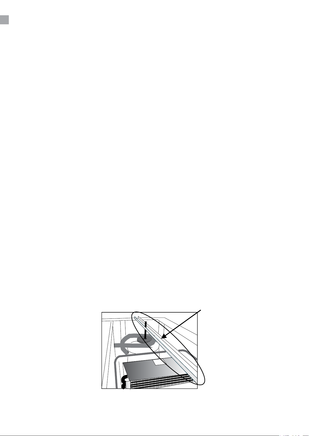
ELANSLUTNING
Kylskåpet är beräknat för anslutning till 230 V/50 Hz. Anslutningen ska göras med en stickkontakt
som bör vara lätt åtkomlig.
Detta kylskåp ska extraskyddas enligt starkströmsbestämmelserna. Detta gäller också även vid
utbyte av ett bentligt kylskåp som inte haft sådant extraskydd.
Använd alltid jordade stickkontakter med tre ledare. Kabelledaren med grön/gul isolering ska jordas
(märkt ).
I alla övriga fall hänvisas till behörig elektriker som kan informera om hur apparaten ges extra skydd.
Om byggnaden saknar extra skydd rekommenderar vi att en elektriker installerar en jordfelsbrytare
(PFI eller HPFI).
DRIFTSSTART
Innan kylskåpet tas i bruk ska det rengöras. Se avsnittet om underhåll.
Viktigt !
Om kylskåpet har legat ner under transporten ska du vänta två (2) timmar innan det startas.
Ta bort transportsäkringen på kompressorn genom att ta bort hela stången enligt g. 1.8.
5
Page 76
VÄNDA DÖRREN
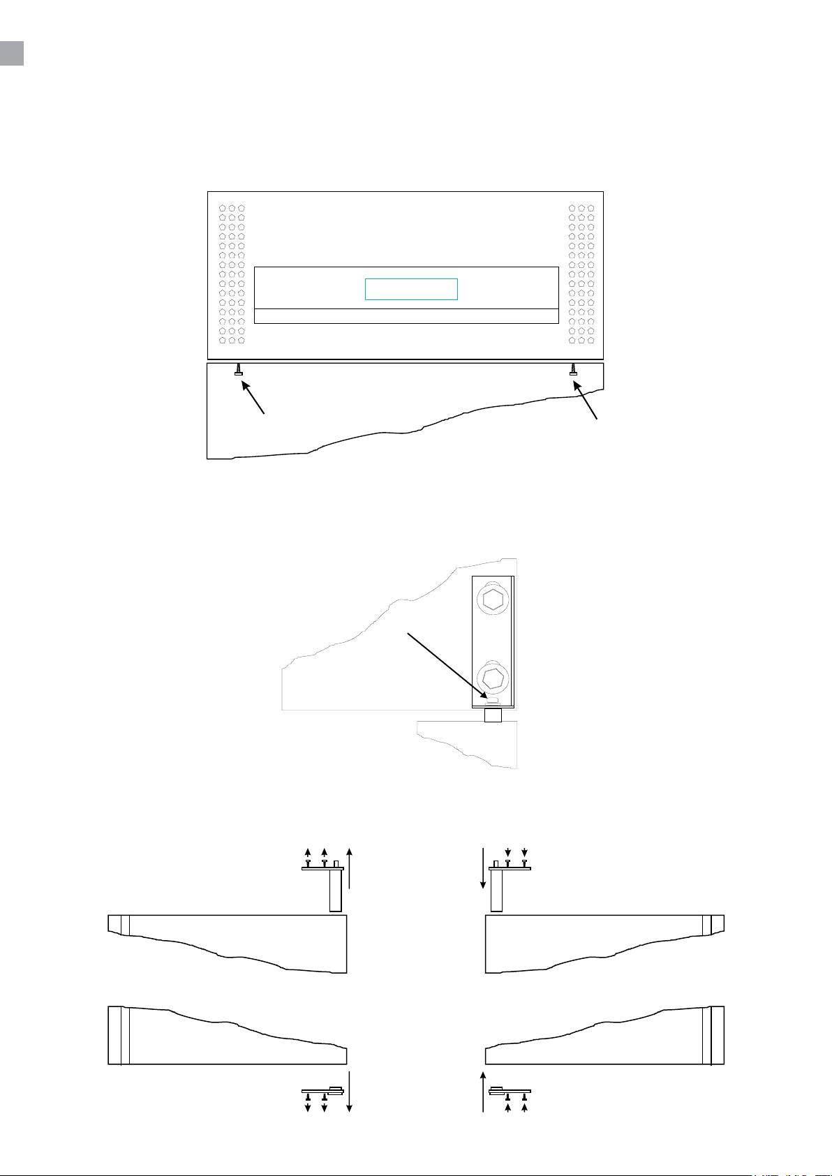
KOM IHÅG att detta ska göras medan dörren är öppen!
Öppna toppen genom att ta bort de markerade skruvarna i g. 1.2.
Ta bort låsskruvarna i dörrfjädern, markerade i g. 1.3, lossa sedan gångjärnet och lyft av dörren.
Lägg ned dörren och växla sedan dörrfjädern och nedre bussningen, se g. 1.4.
6
Page 77
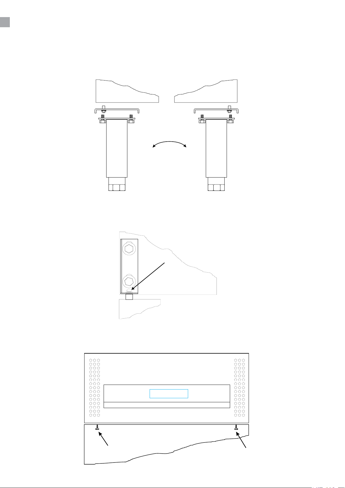
Nedre gångjärnet ska yttas genom att demontera de främre benen/hjulen och därefter montera på
motsatta sidan, se g. 1.5.
Lossa sedan övre gångjärnet på den nya gångjärnssidan och lyft dörren på plats på nedre
gångjärnet. Tryck ner gångjärnet på dörrfjädern och fäst det. Sätt in låsskruvarna (se g. 1.6)
Lås fast och fäst med skruvarna (se g. 1.7).
7
Page 78
TERMOSTATEN
Termostaten är placerad i teknik dörr.
Termostaten är förprogrammerad för skåpet, och oftast behöver inga inställningar justeras.
När skåpet startas kommer displayen att visa den aktuella temperaturen i skåpet.
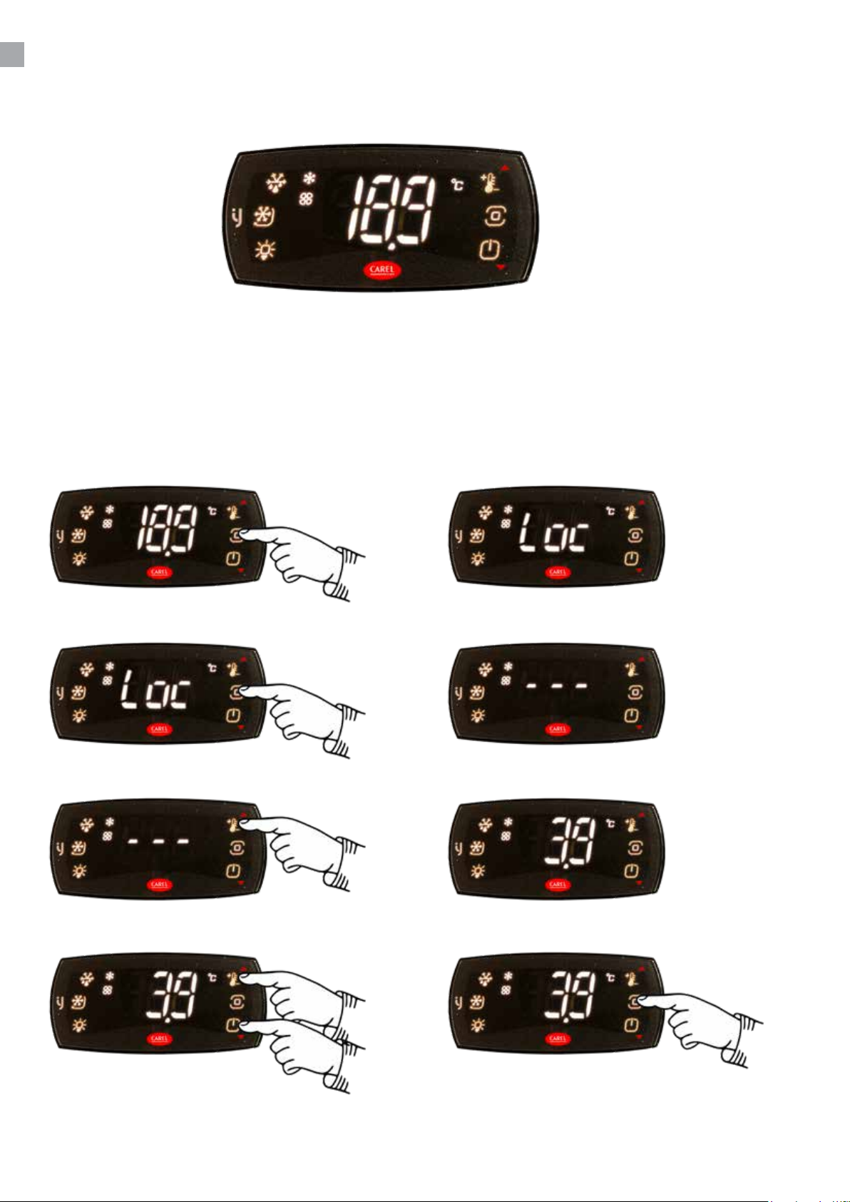
Ställa in ny temperatur:
Tryck på Prg-tangenten. Displayen visar:
Tryck på Prg-tangenten i mer än 3 sekunder. Displayen visar:
Tryck på knappen Set. Displayen visar Inställd temperatur:
Använd piltangenterna för att justera. Tryck på Prg-tangenten för att spara den nya
temperaturen:
Page 79
ÄNDRA PARAMETRARNA
Se parameteröversikt på sida 11.
AVFROSTNING
Skåpet avfrostas automatiskt enligt förprogrammerade intervall. Om skåpet belastas extremt mycket
med återkommande öppningar av dörren eller återkommande byte av innehållet kan en manuell
avfrostning bli nödvändig.
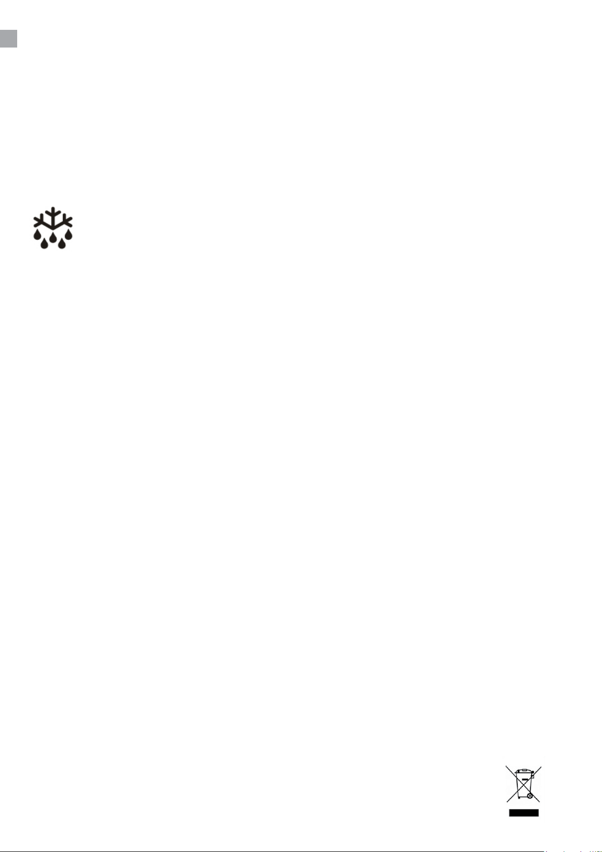
Tryck på den här knappen i minst tre (3) sekunder. Då startar den manuella
avfrostningen och därefter återgår skåpet till normal drift.
Smältvatten leds ut till förångning i en behållare som sitter i kompressorutrymmet.
UNDERHÅLL
Bryt strömmen till kylskåpet genom att dra ut stickkontakten.
Kylskåpet ska rengöras med lämpliga mellanrum. Utvändig och invändig rengöring ska utföras med
en svag tvållösning (milt diskmedel) och därefter ska skåpet torkas av noggrant.
Rengöringsmedel får INTE innehålla klor, klorföreningar eller andra aggressiva medel eftersom de
kan orsaka skador på ytorna och på det interna kylsystemet.
Ventilationsgallret ska rengöras med dammsugare och en styv borste.
SERVICE
Kylsystemet är ett hermetiskt slutet system och kräver ingen tillsyn – endast rengörning.
Vid dålig kylverkan: kontrollera först om orsaken är ett avbrott i stickkontakten eller proppskåpet.
Kontakta återförsäljaren om det inte går att lokalisera felet. Vi ber dig alltid uppge skåpets
typbeteckning och serienummer vid alla kontakter med oss. Informationen sitter på skåpets insida, på
märkskylten överst på högra sidan.
BORTSKAFFANDE
Ett uttjänt kylskåp måste bortskaas på ett miljömässigt försvarbart sätt. Var uppmärksam på vilka
regler som gäller för bortskaande. Det kan nnas särskilda krav och bestämmelser som måste
följas.
9
Page 80

Specications subject to changes without prior notication.
rfj_250311
TEFCOLD A/S, Industrivej 25, DK-8800 Viborg
© TEFCOLD A/S 2025
Page 81
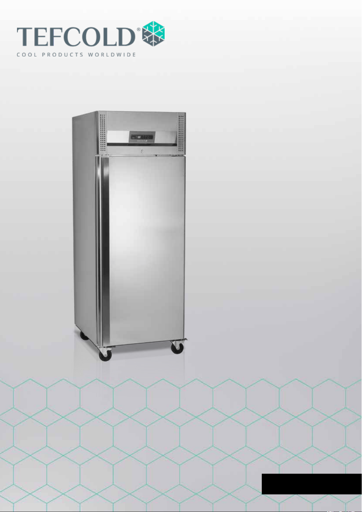
Gastro-Line Upright Cabinets
Users manual
EN 3
Page 82

2
Page 83

CONTENTS
1.
2.
Users manual
Important safety instructions .................................................................................. 4
Unpacking and installation ..................................................................................... 4
Electrical connection .............................................................................................. 5
Start-up of the cabinet ........................................................................................... 5
Door reversal ......................................................................................................... 6
Thermostat ............................................................................................................ 8
Defrosting .............................................................................................................. 9
Maintenance and optimization of energy eciency ............................................... 9
Service ................................................................................................................... 9
Disposal ................................................................................................................. 9
Thermostat Carel ijF
Technical manual ................................................................................................. 11
3
Page 84
IMPORTANT SAFETY INSTRUCTIONS
1. To get the best out of your cabinet, read these instructions thoroughly.
2. The user is responsible for correct use of the cabinet in accordance with instructions.
3. Contact your dealer immediately in the event of faults.
4. Place cabinet in a dry, well ventilated room.
5. Do not place close to sources of heat or in direct sunlight.
6. NB: all electrical appliances can be hazardous.
7. Do not store explosive substances such as gas, petrol, ether or the like in the cabinet.
8. No asbestos or CFC has been used in manufacture.
9. The compressor oil does not contain PCB.
ONLY FOR APPLIANCES WITH REFRIGERANT R290/R600a!
This appliance contains a ammable refrigerant, so make sure of good ventilation
around the appliance. Do not use mechanical devices when defrosting, this can cause
leakage of the cooling system. Do not use electrical appliances inside the refrigerated
storage compartment.
Any repair of the appliance should be carried out by a skilled technician (EN 60335-289: 2010).
Important !
The base of this cabinet is designed for storage of hermetically sealed containers containing
processed food (EN 16825).
UNPACKING AND INSTALLATION
Remove the wooden pallet and the packing. External surfaces are supplied with a protection foil,
which must be removed before installation.
To ensure correct function it is important that the cabinet is level. If the cabinet is supplied with legs,
these can be adjusted.
If you want to build in your cabinet please note the following:
1. There must be at least 15 cm free space above the cabinet in order for the cooling system to
work satisfactorily.
2. There must be sucient space at the hinge side to clean and replace the shelves and clean
around the hinge.
4
Page 85
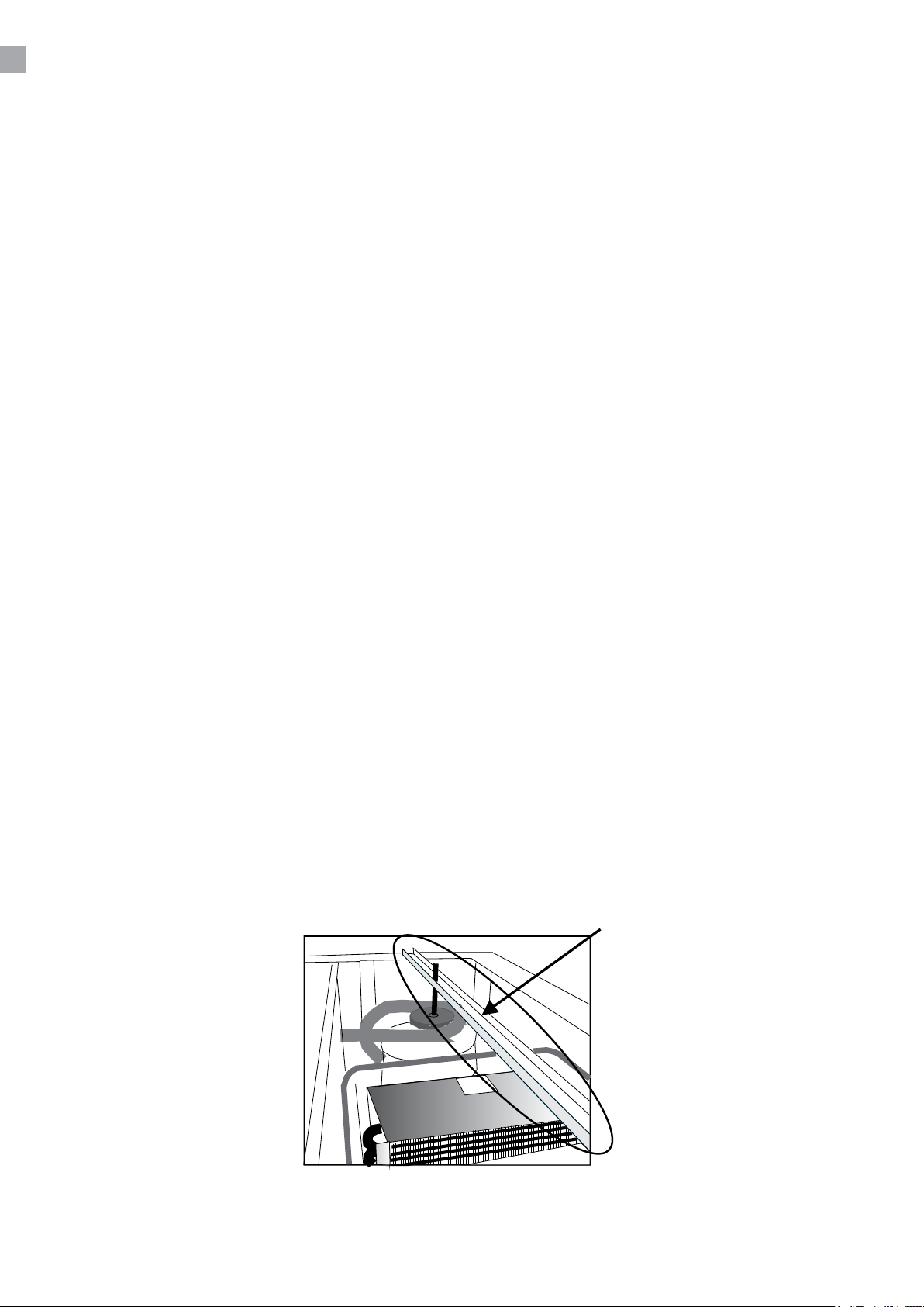
ELECTRICAL CONNECTION
The cabinet operates on 220-240 V/50 Hz.
The wall socket should be easily accessible.
All earthing requirements stipulated by the local electricity authorities must be observed. The cabinet
plug and wall socket should then give correct earthing. If in doubt, contact your local supplier or
authorized electrician.
The main electrical connections must be done by skilled electricians.
START-UP OF THE CABINET
Before use, we recommend that the cabinet is cleaned, see the section on maintenance and
cleaning.
Important !
If the cabinet has been horizontally placed during transport, please wait 2 hours before starting up
the cabinet.
Remember to remove the transport safety device on the compressor. Remove the whole bar as
shown in g. 1.8.
5
Page 86
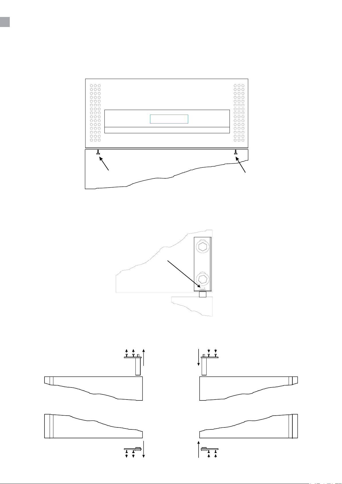
DOOR REVERSAL
NOTE that the following procedure must be made with the door open!
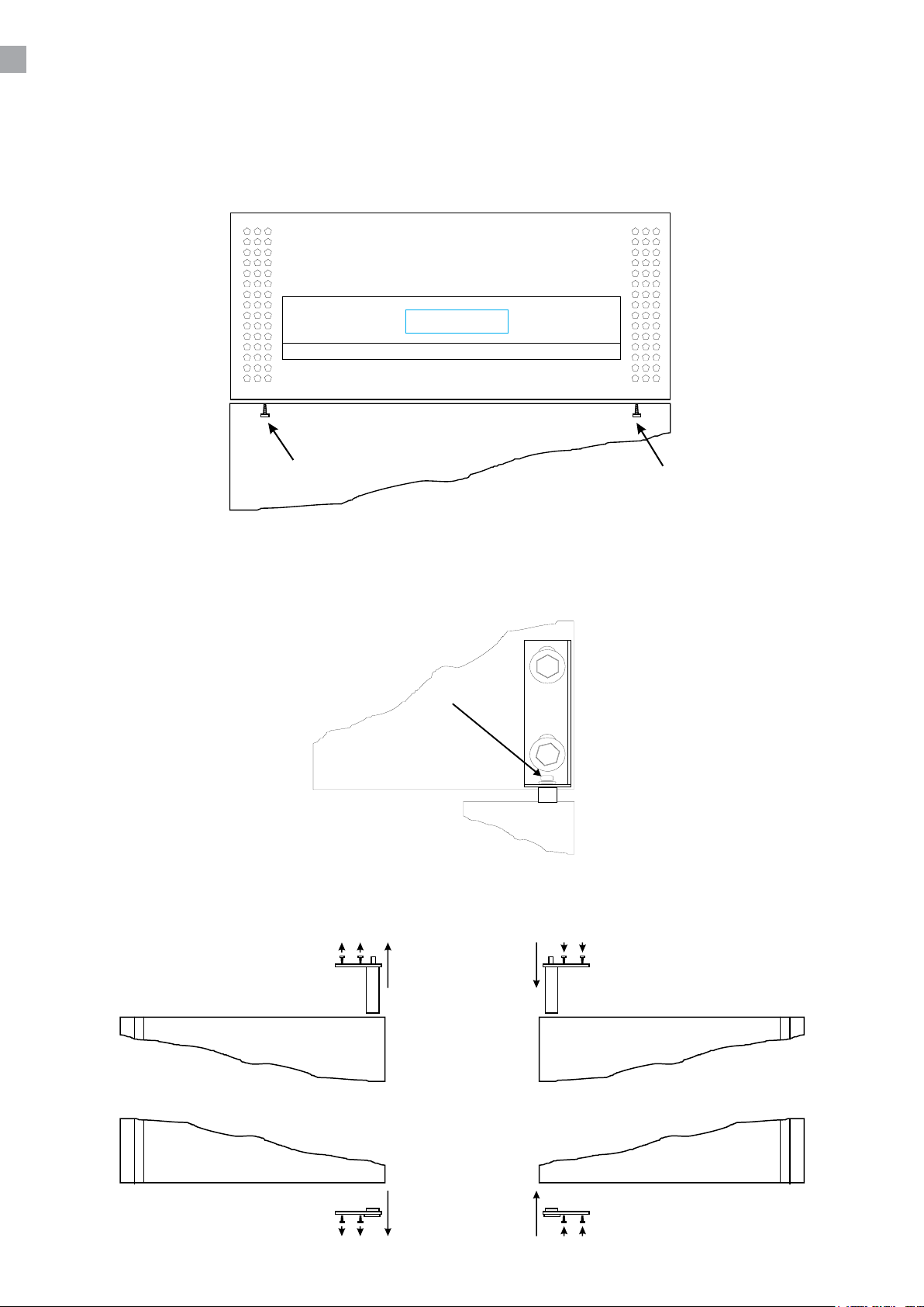
Open the top by removing the screws shown in g. 1.2.
Remove lock screw in door spring as shown in g. 1.3. Loosen the hinge and remove the door.
The door is placed horizontally and the door spring and bottom bush are reversed as in g. 1.4.
6
Page 87
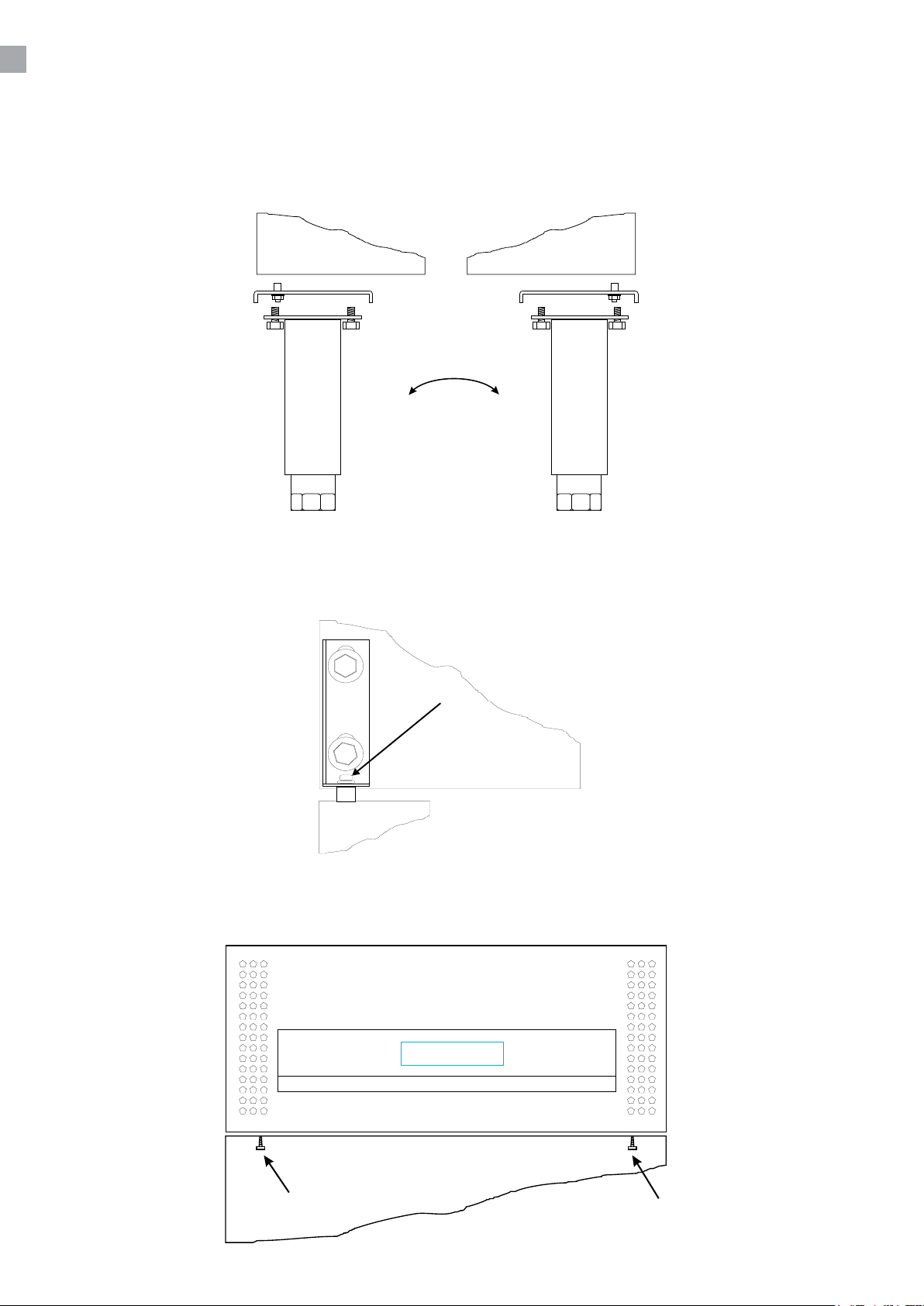
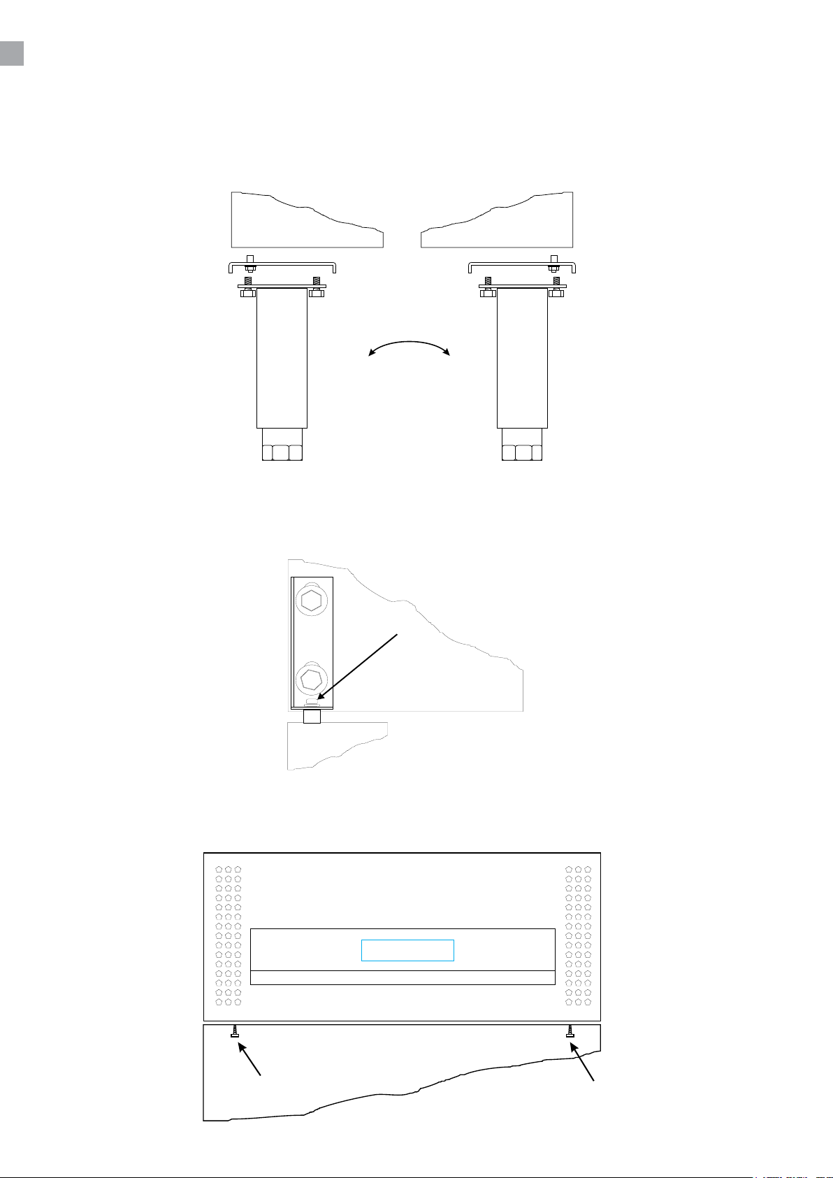
The bottom hinge is reversed by demounting the front legs/wheels and mount them in the other side
of the cabinet as in g. 1.5
Loosen the top hinge in the new hinge side and replace the door on the bottom hinge. The hinge is
pressed downwards on the door spring and is fastened. Put in the lock screw as in g. 1.6
Close and fasten the top with screws as in g. 1.7.
7
Page 88
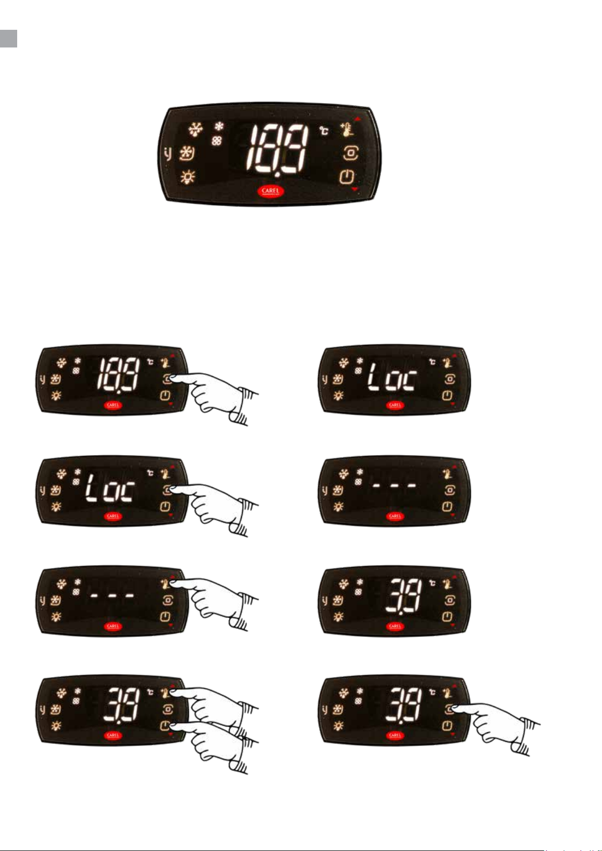
THERMOSTAT
The thermostat is placed in the control panel.
The thermostat has been pre-set and in most cases it is not necessary to adjust the settings.
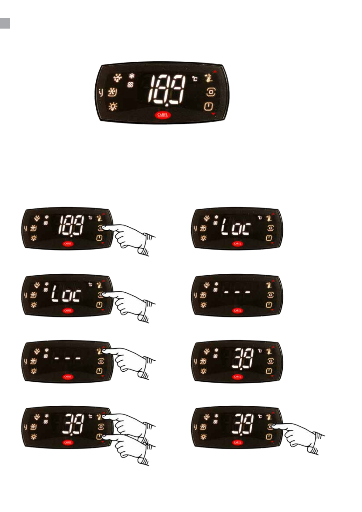
When turning on the cabinet the display will show the current temperature in the cabinet.
Set new temperature:
Press the Prg-key. Display will show:
Press the Prg-key for more than 3 sec. Display will show:
Press the Set-key. Display will show the Set temperature:
Use the Up/Down-keys to change. Use the Prg-key to save the Set temperature:
Page 89
CHANGING OF PARAMETERS
See table of parameters from page 11.
DEFROSTING
The cabinet defrosts automatically with pre-set intervals. If the door to the cabinet is opened or
the contents of the cabinet is changed frequently it may become necessary to defrost the cabinet
manually.
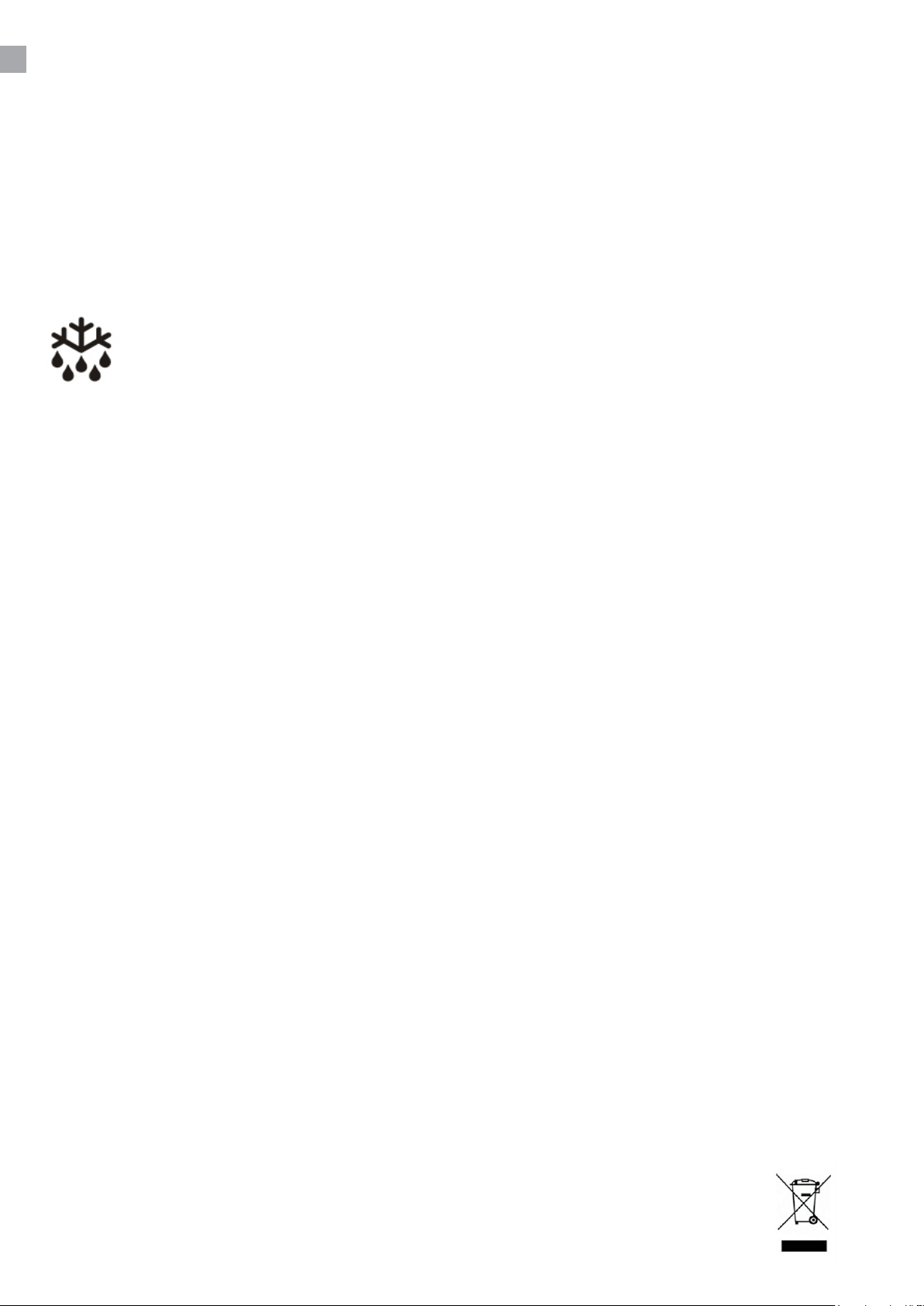
Pressing this key continuously for more than 3 seconds will start a manual defrosting
and then return to normal operation.
Defrosted water runs to a container placed in the compressor compartment and evaporates.
CLEANING AND MAINTENANCE
Switch o the electrical connection at the socket.
The cabinet must be periodically cleaned. Clean the external and internal surfaces of the cabinet with
a light soap solution and subsequently wipe dry.
Do not spray the appliance with direct jets of water or using high pressure appliances.
Do NOT use cleansers containing chlorine or other harsh cleansers, as these can damage the
surfaces and the internal cooling system.
Clean the condenser and the compressor compartment using a vacuum cleaner and a sti brush.
SERVICE
The cooling system is a hermetically sealed system and does not require supervision, only cleaning.
If the cabinet fails to cool, check if the reason is a power cut.
If you cannot locate the reason to the failure of the cabinet, please contact your supplier. Please
inform model and serial number of the cabinet. You can nd this information on the rating label which
is placed inside the cabinet in the top right hand side.
DISPOSAL
Disposal of the cabinet must take place in an environmentally correct way. Please note existing
regulation on disposal. There may be special requirements and conditions which must be observed.
9
Page 90

Specications subject to changes without prior notication.
rfj_250311
TEFCOLD A/S, Industrivej 25, DK-8800 Viborg
© TEFCOLD A/S 2025
Page 91
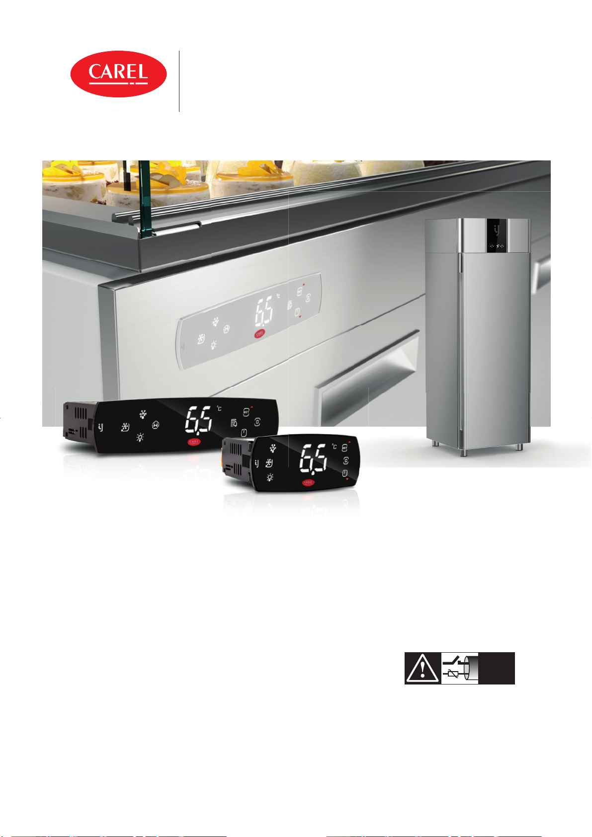
iJF
Electronic controller for food storage and display units
ENG
USER MANUAL
iJF
+0300100EN - ENG
Up to date version available on
www.carel.com
NO POWER
& SIGNAL
CABLES
TOGETHER
READ CAREFULLY IN THE TEXT!
Page 92

Page 93
ENG
GENERAL WARNINGS
CAREL bases the development of its products on decades of experience
in HVAC, on continuous investments in technological innovations to products, procedures and strict quality processes with in-circuit and functional
testing on 100% of its products, and on the most innovative production
technology available on the market. CAREL and its subsidiaries/a liates
nonetheless cannot guarantee that all the aspects of the product and the
software included with the product respond to the requirements of the
nal application, despite the product being developed according to startof-the-art techniques. The customer (manufacturer, developer or installer
of the nal equipment) accepts all liability and risk relating to the con guration of the product in order to reach the expected results in relation
to the speci c nal installation and/or equipment. CAREL may, based on
speci c agreements, act as a consultant for the successful commissioning
of the nal unit/application, however in no case does it accept liability for
the correct operation of the nal equipment/system. The CAREL product
is a state-of-the-art product, whose operation is speci ed in the technical
documentation supplied with the product or can be downloaded, even
prior to purchase, from the website www.carel.com. Each CAREL product,
in relation to its advanced level of technology, requires setup/con guration/programming/commissioning to be able to operate in the best possible way for the speci c application. Failure to complete such operations,
which are required/indicated in the user manual, may cause the nal product to malfunction; CAREL accepts no liability in such cases. Only quali ed
personnel may install or carry out technical service on the product. The
customer must only use the product in the manner described in the documentation relating to the product. In addition to observing any further
warnings described in this manual, the following warnings must be heeded for all CAREL products:
• prevent the electronic circuits from getting wet. Rain, humidity and
all types of liquids or condensate contain corrosive minerals that may
damage the electronic circuits. any case, the product should be used or
stored in environments that comply with the temperature and humidity
limits speci ed in the manual;
• do not install the device in particularly hot environments. Too high temperatures may reduce the life of electronic devices, damage them and
deform or melt the plastic parts. In any case, the product should be used
or stored in environments that comply with the temperature and humidity limits speci ed in the manual;
• do not attempt to open the device in any way other than described in
the manual.
• do not drop, hit or shake the device, as the internal circuits and mechanisms may be irreparably damaged;
• do not use corrosive chemicals, solvents or aggressive detergents to
clean the device;
• do not use the product for applications other than those speci ed in the
technical manual.
All of the above suggestions likewise apply to the controllers, serial cards,
programming keys or any other accessory in the CAREL product portfolio.
CAREL adopts a policy of continual development. Consequently, CAREL
reserves the right to make changes and improvements to any product
described in this document without prior warning. The technical speci cations shown in the manual may be changed without prior warning.
The liability of CAREL in relation to its products is speci ed in the CAREL general contract conditions, available on the website www.carel.com
and/or by speci c agreements with customers; speci cally, to the extent
where allowed by applicable legislation, in no case will CAREL, its employees or subsidiaries/a liates be liable for any lost earnings or sales, losses
of data and information, costs of replacement goods or services, damage
to things or people, downtime or any direct, indirect, incidental, actual,
punitive, exemplary, special or consequential damage of any kind whatsoever, whether contractual, extra-contractual or due to negligence, or any
other liabilities deriving from the installation, use or impossibility to use
the product, even if CAREL or its subsidiaries/a liates are warned of the
possibility of such damage.
DISPOSAL
Fig. 1 Fig. 2
INFORMATION FOR USERS ON THE CORRECT HANDLING OF WASTE
ELECTRICAL AND ELECTRONIC EQUIPMENT (WEEE)
The product is made up of metal parts and plastic parts. In reference to European Union directive 2002/96/EC issued on 27 January 2003 and related
national legislation, please note that:
• WEEE cannot be disposed of as municipal waste and such waste must
be collected and disposed of separately;
• the public or private waste collection systems de ned by local legislation must be used. In addition, the equipment can be returned to the
distributor at the end of its working life when buying new equipment;
• the equipment may contain hazardous substances: the improper use or
incorrect disposal of such may have negative e ects on human health
and on the environment;
• the symbol (crossed-out wheeled bin) shown on the product or on the
packaging and on the technical lea et indicates that the equipment has
been introduced onto the market after 13 August 2005 and that it must
be disposed of separately;
• in the event of illegal disposal of electrical and electronic waste, the
penalties are speci ed by local waste disposal legislation
Warranty on materials: 2 years (from production date, excluding consumables).
Approval: the quality and safety of CAREL S.p.A. products are guaranteed
by the ISO 9001 certi ed design and production system.
NO POWER
& SIGNAL
CABLES
READ CAREFULLY IN THE TEXT!
Separate as much as possible the probe and digital input cables from
cables to inductive loads and power cables, so as to avoid possible
electromagnetic disturbance. Never run power cables (including the
electrical panel cables) and signal cables in the same conduits.
Key to the symbols:
Caution: to bring critical issues to the attention of those using the product.
Notice: to focus attention on important topics; in particular the practical
application of the various product functions.
Caution: this product is to be integrated and/or incorporated into the
nal apparatus or equipment. Veri cation of conformity to the laws and
technical standards in force in the country where the nal apparatus or
equipment will be operated is the manufacturer’s responsibility. Before
delivering the product, Carel has already completed the checks and tests
required by the relevant European directives and harmonised standards,
using a typical test setup, which however cannot be considered as representing all possible conditions of the nal installation.
TOGETHER
.
HACCP: CAUTION
Food Safety programs based on procedures such as HACCP and, more
generally, certain national regulations, require that the devices used for
food storage be periodically checked to ensure that measurement errors
are within the limits allowed for the application used. Carel recommends
users to follow, for example, the indications of the European standard
“Temperature recorders and thermometers for the transport, storage
and distribution of chilled, frozen, deep-frozen/quick-frozen food and ice
cream - PERIODIC VERIFICATION”, EN 13486 - 2001 (or subsequent updates)
or similar regulations and provisions in force in the country in question.
Further information can be found in the manual regarding the technical
characteristics, correct installation and con guration of the product.
iJF +0300100EN rel. 1.3 - 29.04.2022
Warnings
3
Page 94

Page 95

Index
ENG
1. Introduction ............................................................... 7
1.1 Functions and main features .....................................................................7
1.2 Models and accessories ................................................................................ 8
2. Installation ............................................................... 13
2.1 Warnings ............................................................................................................. 13
2.2 Small version for front panel mounting ..........................................13
2.3 Small version with SPLIT mounting ....................................................14
2.4 Large version for front panel mounting .......................................... 16
2.5 Large version with SPLIT mounting ...................................................17
2.6 Small version with remote HMI terminal ........................................18
2.7 Large version with remote HMI terminal ........................................ 20
2.8 Description of the terminals ...................................................................21
2.9 Probe connections ........................................................................................ 23
2.10 Connection diagrams ................................................................................. 24
2.11 Positioning inside the panel ................................................................... 24
2.12 Electrical installation .................................................................................... 24
2.13 Serial port connections .............................................................................. 25
2.14 Installation ..........................................................................................................25
3. Con guration tools .................................................26
3.1 Spark: con guration and commissioning software .................26
3.2 Sparkly: command-line con guration and commissioning
software .......................................................................................................................... 26
3.3 Applica app and Controlla ....................................................................... 27
3.4 Applica Desktop ............................................................................................. 27
4. User interface ...........................................................28
4.1 Introduction ......................................................................................................28
4.2 Models with user terminal or remote HMI .....................................29
4.3 SPLIT models without user terminal .................................................. 33
5. Commissioning........................................................ 34
5.1 Description of the initial con guration parameters.................34
5.2 Set date/time and time bands .............................................................. 36
5.3 Checks after commissioning .................................................................. 36
7. Parameter table .......................................................84
7.1 Parameter table ............................................................................................... 84
7.2 Con guring the iJF controller via the Applica app ...................92
8. Technical speci cations ......................................... 94
8.1 Connector/cable table ............................................................................... 96
9. Alarms and signals .................................................. 97
9.1 Signals ................................................................................................................... 97
9.2 Types of alarms ................................................................................................ 97
9.3 Alarm table ........................................................................................................ 98
9.4 Low and high temperature alarms LO and HI .............................99
9.5 HACCP alarms (HACCP = Hazard Analysis and Critical Control
Point) ............................................................................................................................. 100
9.6 Dirty condenser alarm ............................................................................. 101
9.7 Frost protection alarm ............................................................................. 101
9.8 Refrigerant leak alarm rSF ...................................................................... 102
9.9 Maintenance alarm .................................................................................... 102
9.10 VCC compressor alarms with serial control ................................ 103
10. Logs .........................................................................104
10.1 Periodic logs ................................................................................................... 104
10.2 Event log .......................................................................................................... 104
11. Appendix ................................................................ 105
11.1 ir33 and IJ parameter compatibility table ................................... 105
11.2 Input/output con guration procedure ........................................ 107
11.3 Setting the default parameters/loading the parameter sets ...
108
11.4 Copy con guration parameters ........................................................ 109
11.5 Preparing and using the con gurations ......................................109
12. Release notes ......................................................... 110
6. Functions .................................................................. 37
6.1 ON/OFF ................................................................................................................37
6.2 Inputs and outputs ....................................................................................... 38
6.3 Digital inputs .................................................................................................... 40
6.4 Analogue outputs ......................................................................................... 43
6.5 Digital outputs ................................................................................................. 43
6.6 Control .................................................................................................................. 47
6.7 Control modes ................................................................................................. 49
6.8 Night-time operation .................................................................................. 52
6.9 ECO operation ................................................................................................. 53
6.10 Continuous cycle ........................................................................................... 53
6.11 Custom set points ......................................................................................... 54
6.12 Compressor ...................................................................................................... 54
6.13 Compressor protection times ................................................................ 54
6.14 Variable capacity compressor (VCC) .................................................. 55
6.15 Pump down ...................................................................................................... 60
6.16 Defrost .................................................................................................................. 61
6.17 Evaporator fans ............................................................................................... 68
6.18 Condenser fans ............................................................................................... 72
6.19 Humidity management ............................................................................. 74
6.20 Light management.......................................................................................77
6.21 Door management ....................................................................................... 77
6.22 Door - light interactions ............................................................................78
6.23 Curtain management..................................................................................78
6.24 Generic functions .......................................................................................... 79
6.25 Anti-sweat heater or fan ............................................................................ 81
6.26 Gasket heater ...................................................................................................82
6.27 Drain heater ....................................................................................................... 82
6.28 Temperature monitoring .......................................................................... 83
6.29 High and low voltage protection (HLVP) ....................................... 83
iJF +0300100EN rel. 1.3 - 29.04.2022
Index
5
Page 96

Page 97

1. INTRODUCTION
iJF is the range of CAREL electronic controls designed for commercial refrigeration food storage and display applications. The
range comprises SMALL and LARGE formats, which di er in terms of the number of inputs/outputs and buttons available. Both
formats allow di erent mounting methods: FRONT PANEL mounting with built-in display or SPLIT mounting, with or without
REMOTE HMI DISPLAY. All models come with 115 - 230 Vac switching power supply and NFC (Near Field Communication) connectivity. All standard iJF display interfaces use backlit buttons with a capacitive touch screen.
A vast catalogue of options for integration into the device is available across the entire iJF range:
• Bluetooth to interact in real time with the chiller and access the data logs stored on the controller. Bluetooth antenna for
connection to the Applica (service) and CONTROLLA apps (end user).
• Modbus over RS485 for connection to Carel or third-party supervisory systems (no external converter needed).
• VCC serial output to directly drive a VCC (variable capacity compressor) via serial link, without external adapters.
• Modulating outputs (0-10 V/PWM) to directly drive modulating loads such as frequency-controlled VCC compressors, dimmable lights or variable-speed fans.
• Humidity input to directly read a 0-5 V ratiometric humidity probe.
• Safety package with compressor protection against high and low power supply voltages (HLVP) and zero crossing function
for the relays.
• RTC clock
• Di erent combinations of colours and keypads for the display.
The entire iJF range is integrated into the following CAREL support software and apps:
• Spark software for OEM technical departments; connection via RS485, BMS or port ID2 with speci c converters.
• Applica Desktop software for OEM technical departments; connection via RS485, BMS or port ID2 with speci c converters.
• Sparkly software for OEM production lines; connection via RS485.
• Applica app for technical service in the eld; connection via NFC and BT.
• Controlla app for end users; connection via BT.
ENG
1.1 Functions and main features
The functions and most of the parameters available on the iJF range are mainly derived from the Carel ir33+ range. In addition
to these, the following functions have been added:
• Read/write parameters via NFC (replacing the programming key).
• Temperature control in the dead band.
• Defrost drain heater.
• Fan cycles to avoid air strati cation.
• Fan management for humidity levels (no dedicated probe needed).
• Door gasket heater.
• High and low power supply voltage detection.
• Refrigeration system failure alarm (rSF).
The iJF range has been designed to o er maximum exibility through the use of modular hardware.
Main features of the basic versions:
• SMALL models, 4 inputs and up to 4 relays.
• LARGE models, 5 inputs and up to 6 relays.
• panel mounting with built-in display.
• split version with remote display.
• split version without remote display.
• 115-230 Vac +-10% (90-264 Vac) switching power supply.
• NFC connectivity.
Fully-integrated options:
• Bluetooth (with real time clock).
• Real time clock.
• 1 RS485 serial port for supervisor with Modbus protocol.
• 1 VCC serial port (*).
• 2 modulating outputs (0-10V/PWM/VCC by frequency) (*).
• 1 x 0-5 V ratiometric input (*).
• Compressor protection against high and low power supply voltages (HLVP) and zero crossing function for the relays.
(*) versions are mutually exclusive
iJF +0300100EN rel. 1.3 - 29.04.2022
Introduction
7
Page 98
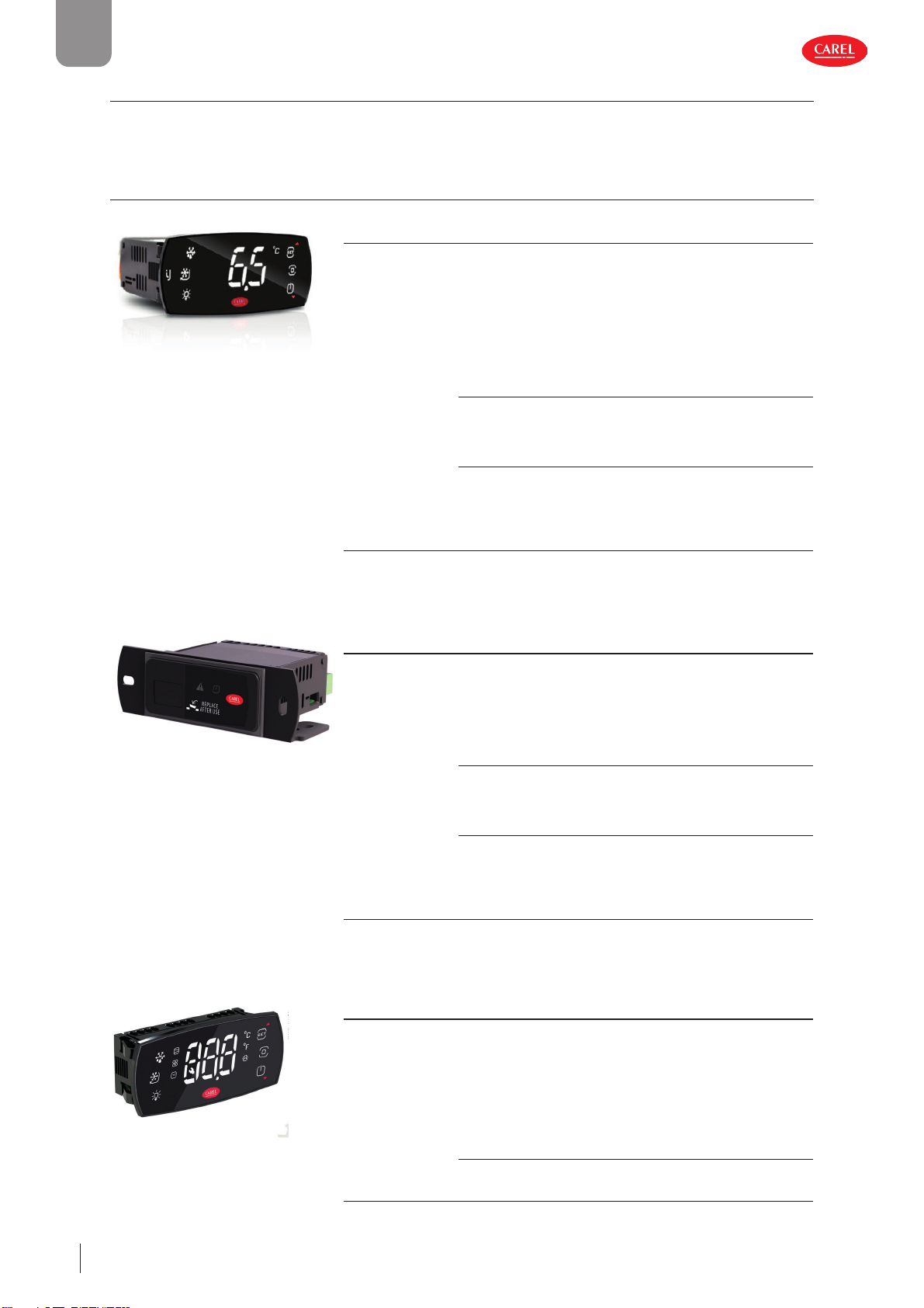
ENG
1.2 Models and accessories
Below are the features of the iJF models, divided by format and mounting.
Each product group can be identi ed based on the rst 6 digits of the part number; please contact CAREL for the complete part
numbers of the products available and the corresponding technical speci cations.
1.2.1 SMALL controllers
FRONT PANEL mounting with built-in display
P/N ( rst 6 digits) Description
IJFPSA Basic features:
• switching power supply, 115-230 Vac with high and low voltage detection;
• NFC;
• 2 probe inputs, 1 digital input, 1 multifunction input;
• max 4 relays (2HP 8A 5A 5A);
• removable, screw or fast-on terminals;
• single or multiple pack;
• black or white faceplate (*);
• white or red digits (*);
• 6 backlit touch buttons.
(*) Di erent colours available on custom models.
Optional features:
• Bluetooth with RTC;
• RTC;
• HLVP, ZC;
• 1 RS485 serial port for supervision.
Mutually-exclusive options:
• 1 VCC serial port;
• 2 modulating outputs (0-10V/PWM/VCC by frequency, selectable for each
output);
• 1 x 0-5 V ratiometric input;
• 1 RS485 Fieldbus serial port (secondary Modbus protocol only).
Fig. 1.a Tab. 1.a
SPLIT mounting
P/N ( rst 6 digits) Description
IJFSSA Basic features:
• switching power supply, 115-230 Vac with high and low voltage detection;
• NFC;
• 2 probe inputs, 1 digital input, 1 multifunction input;
• max 4 relays (2HP 8A 5A 5A);
• removable, screw or faston terminals;
• single or multiple pack;
• JST connector at front for connection to remote display.
Optional features:
• Bluetooth with RTC;
• RTC;
• HLVP, ZC;
• 1 RS485 serial port for supervision.
Mutually-exclusive options:
• 1 VCC serial port;
• 2 modulating outputs (0-10V/PWM/VCC by frequency, selectable for each
output);
• 1 x 0-5 V ratiometric input;
• 1 RS485 Fieldbus serial port (secondary Modbus protocol only).
Fig. 1.b Tab. 1.b
Remote HMI terminal
P/N ( rst 6 digits) Description
300100_016_R01
IJFHSA Basic features:
• low voltage power supply from the controller;
• NFC;
• single or multiple pack;
• mini JST terminal for connection to the controller, xed screw or removable;
• black or white faceplate (*);
• white or red digits (*);
• 6 backlit touch buttons.
(*) Di erent colours available on custom models.
Optional features:
• Bluetooth;
• 1 multifunction input, xed screw or removable terminal.
Fig. 1.c Tab. 1.c
Introduction
8
iJF +0300100EN rel. 1.3 - 29.04.2022
Page 99
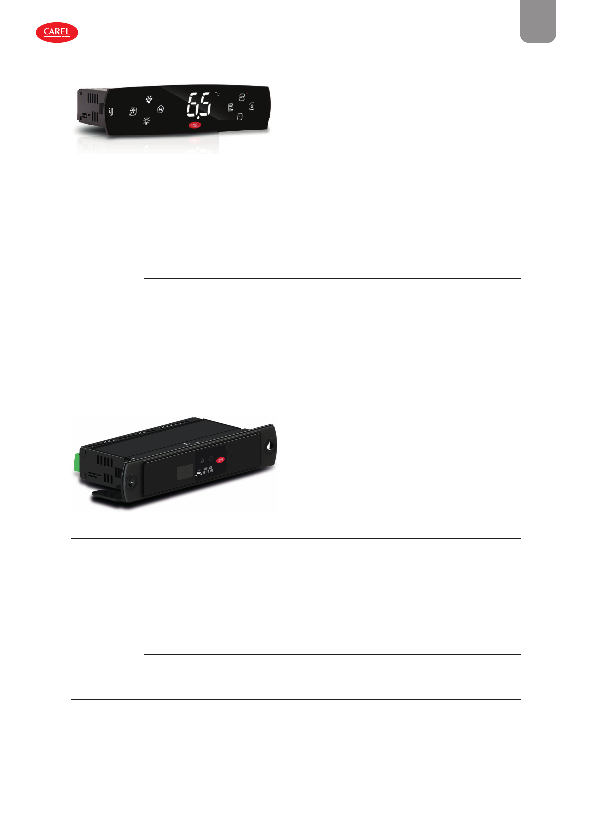
1.2.2 LARGE controllers
FRONT PANEL mounting with built-in display
Fig. 1.d
P/N ( rst 6 digits) Description
IJFPLA Basic features:
• switching power supply, 115-230 Vac with high and low voltage detection;
• NFC;
• 3 probe inputs, 1 digital input, 1 multifunction input;
• max 6 relays (2HP 16A 8A 8A 8A 8A or 30A 16A 8A 8A 8A 8A);
• removable, screw or faston terminals;
• single or multiple pack;
• black or white faceplate (*);
• white or red digits (*);
• 8 backlit touch buttons.
(*) Di erent colours available on custom models.
Optional features:
• Bluetooth with RTC;
• RTC;
• HLVP, ZC;
• 1 RS485 serial port for supervision.
Mutually-exclusive options:
• 1 VCC serial port;
• 2 modulating outputs (0-10V/PWM/VCC by frequency, selectable for each output);
• 1 x 0-5 V ratiometric input;
• 1 RS485 Fieldbus serial port (secondary Modbus protocol only).
ENG
Tab. 1.d
SPLIT mounting
Fig. 1.e
P/N ( rst 6 digits) Description
IJFSLA Basic features:
• switching power supply, 115-230 Vac with high and low voltage detection;
• NFC;
• 2 probe inputs, 1 digital input, 1 multifunction input;
• max 6 relays (2HP 16A 8A 8A 8A 8A or 30A 16A 8A 8A 8A 8A);
• removable, screw or faston terminals;
• single or multiple pack;
• JST terminal at front for connection to remote display.
Optional features:
• Bluetooth with RTC;
• RTC;
• HLVP, ZC;
• 1 RS485 serial port for supervision.
Mutually-exclusive options:
• 1 VCC serial port;
• 2 modulating outputs (0-10V/PWM/VCC by frequency, selectable for each output);
• 1 x 0-5 V ratiometric input;
• 1 RS485 Fieldbus serial port (secondary Modbus protocol only).
300100_019_R01
Tab. 1.e
iJF +0300100EN rel. 1.3 - 29.04.2022
Introduction
9
Page 100
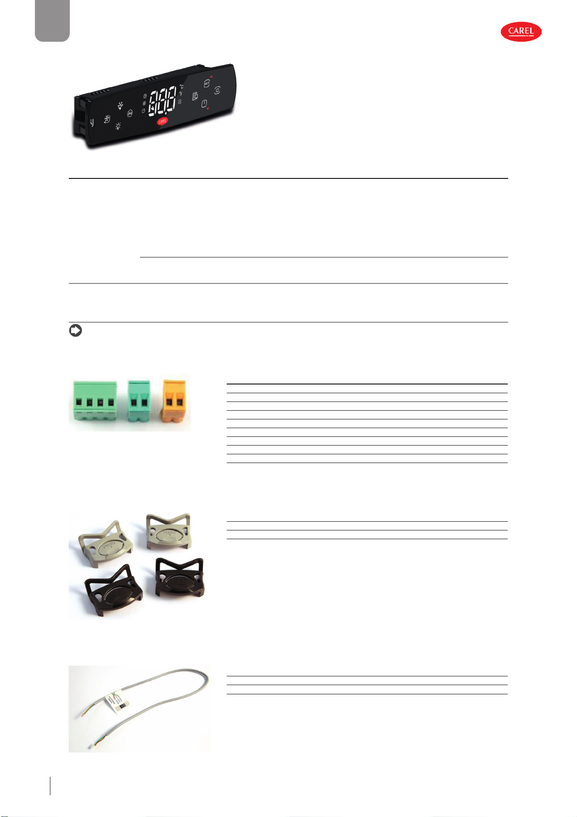
ENG
Remote HMI terminal
300100_018_R01
Fig. 1.f
P/N ( rst 6 digits) Description
IJFHLA Basic features:
• low voltage power supply from the controller;
• NFC;
• single or multiple pack;
• JST terminal for connection to the controller, xed screw or removable;
• black or white faceplate (*);
• white or red digits (*);
• 8 backlit touch buttons.
(*) Di erent colours available on custom models.
Optional features:
• Bluetooth;
• 1 probe input, 1 digital input, 1 multifunction input, with xed screw or removable terminals.
Tab. 1.f
1.2.3 Accessories
Notice: This list of ACCESSORY part numbers is updated as of the release date of this manual; please contact CAREL for any
additional part numbers available.
Connector kit
P/N Description
BXOPZB35002B1 removable connector kit, 2-pin, 3.5 mm pitch, black (10 pcs)
300100_023_R01
Fig. 1.g Tab. 1.g
Fixing brackets
BXOPZB35003B1 removable connector kit, 3-pin, 3.5 mm pitch, black (10 pcs)
BXOPZB38102G1 removable connector kit, 2-pin, 3.81 mm pitch, green (10 pcs)
BXOPZB38104G1 removable connector kit, 4-pin, 3.81 mm pitch, green (10 pcs)
BXOPZB38105G1 removable connector kit, 5-pin, 3.81 mm pitch, green (10 pcs)
BXOPZB50802O1 removable connector kit, 2-pin, 5.08 mm pitch, orange (10 pcs)
BXOPZB50803G1 removable connector kit, 3-pin, 5.08 mm pitch, green (10 pcs)
BXOPZB50805G1 removable connector kit, 5-pin, 5.08mm pitch, green (10 pcs)
BXOPZB50807G1 removable connector kit, 7-pin, 5.08 mm pitch, green (10 pcs)
P/N Description
BXOPZMBRC0002 Built-in version panel bracket kit, multiple pack (20 pcs)
300100_022_R01
ACS00CK001602 panel bracket kit for HMI version multiple pack (20 pcs)
Tab. 1.h
10
Fig. 1.h
Cables
Fig. 1.i
Introduction
P/N Description
BXOPZC3000050 3-wire cable jst mini/free end 50 cm (1 pc)
BXOPZC3S00250 3-wire cable jst mini/free end shielded 250 cm (1 pc)
Tab. 1.i
300100_012_R01
iJF +0300100EN rel. 1.3 - 29.04.2022
 Loading...