

Page 1
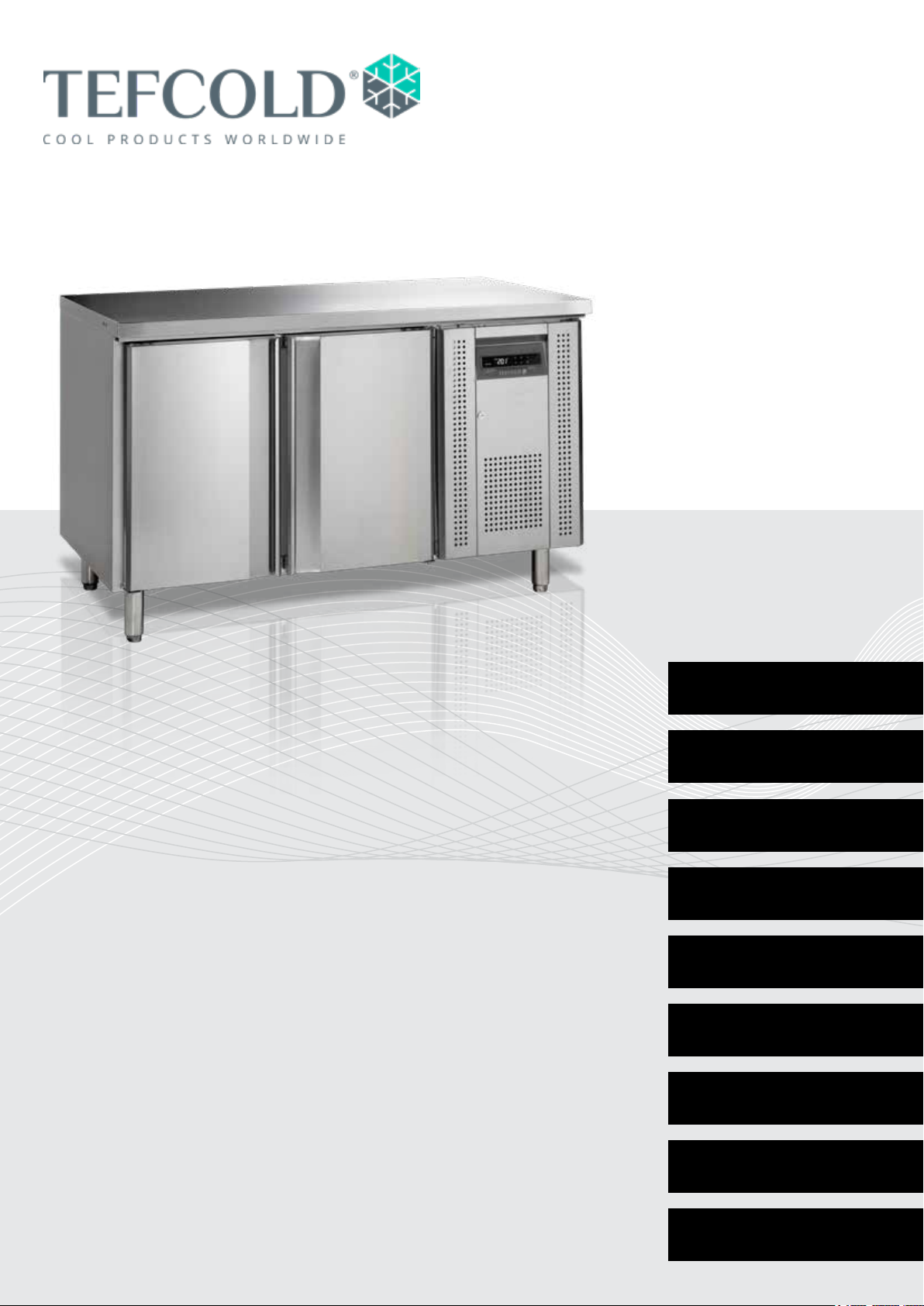
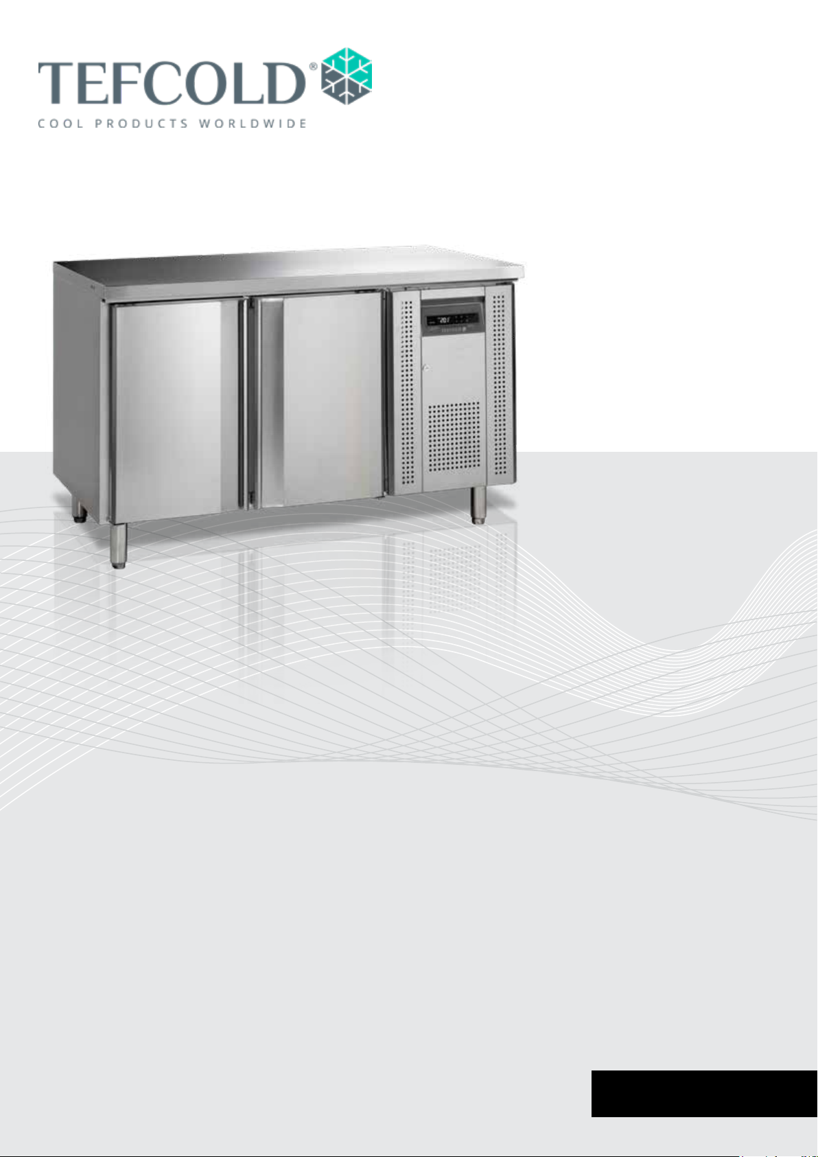
Gastro-Line Counters
Users manual
Models:
CK Series
CF Series
SK Series
BK Series
UC Series
EN
DE
DK
SV
FR
IT 41
ES 49
1
9
17
25
33
SS Series
PT Series
PT 57
RUS 65
Page 2

2
Page 3

CONTENTS
1.
2.
Users manual
Important safety instructions .................................................................................. 4
Unpacking and installation ..................................................................................... 4
Electrical connection .............................................................................................. 5
Start-up of the cabinet ........................................................................................... 5
Thermostat ............................................................................................................ 6
Defrosting .............................................................................................................. 7
Maintenance and optimization of energy eciency ............................................... 7
Service ................................................................................................................... 7
Disposal ................................................................................................................. 7
Electrical circuit diagramme.................................................................................. 73
Thermostat technical manuals
Dixell XW20LRH .................................................................................................. 74
3.
Dixell XW60LRH .................................................................................................. 79
EPREL
EPREL data .......................................................................................................... 85
3
Page 4

IMPORTANT SAFETY INSTRUCTIONS
1. To get the best out of your cabinet, read these instructions thoroughly.
2. The user is responsible for correct use of the cabinet in accordance with instructions.
3. Contact your dealer immediately in the event of faults.
4. Place cabinet in a dry, well ventilated room.
5. Do not place close to sources of heat or in direct sunlight.
6. NB: all electrical appliances can be hazardous.
7. Do not store explosive substances such as gas, petrol, ether or the like in the cabinet.
8. No asbestos or CFC has been used in manufacture.
9. The compressor oil does not contain PCB.
ONLY FOR APPLIANCES WITH REFRIGERANT R290/R600a!
This appliance contains a ammable refrigerant, so make sure of good ventilation
around the appliance. Do not use mechanical devices when defrosting, this can cause
leakage of the cooling system. Do not use electrical appliances inside the refrigerated
storage compartment.
Any repair of the appliance should be carried out by a skilled technician (EN 60335-289: 2010).
Important !
The base of this cabinet is designed for storage of hermetically sealed containers containing
processed food (EN 16825).
UNPACKING AND INSTALLATION
Remove the wooden pallet and the packing. External surfaces are supplied with a protection foil,
which must be removed before installation.
To ensure correct function it is important that the cabinet is level. If the cabinet is supplied with legs,
these can be adjusted.
4
Page 5

ELECTRICAL CONNECTION
The cabinet operates on 220-240 V/50 Hz.
The wall socket should be easily accessible.
All earthing requirements stipulated by the local electricity authorities must be observed. The cabinet
plug and wall socket should then give correct earthing. If in doubt, contact your local supplier or
authorized electrician.
The main electrical connections must be done by skilled electricians.
START-UP OF THE CABINET
Before use, we recommend that the cabinet is cleaned, see the section on maintenance and
cleaning.
Important !
If the cabinet has been horizontally placed during transport, please wait 2 hours before starting up
the cabinet.
5
Page 6
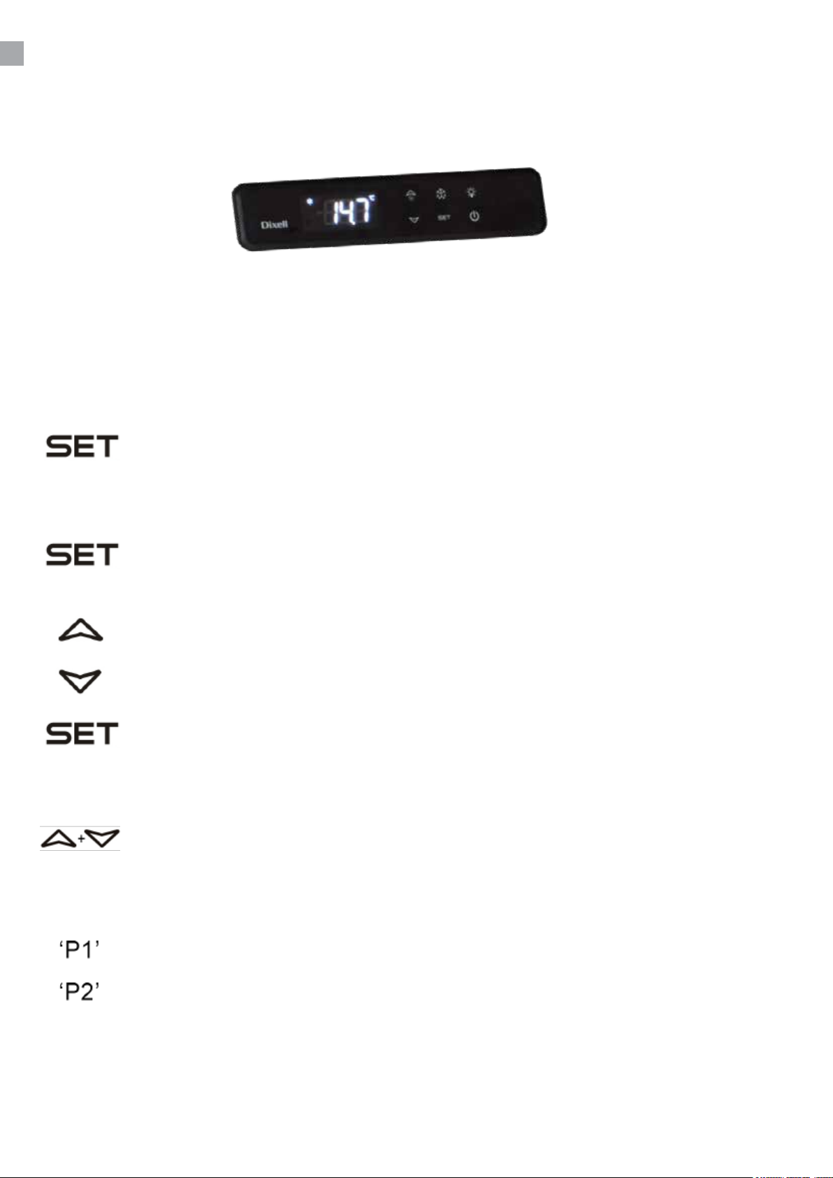
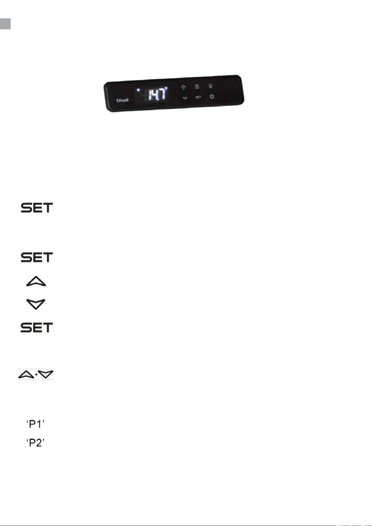
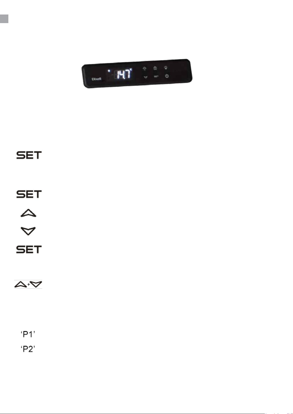
THERMOSTAT
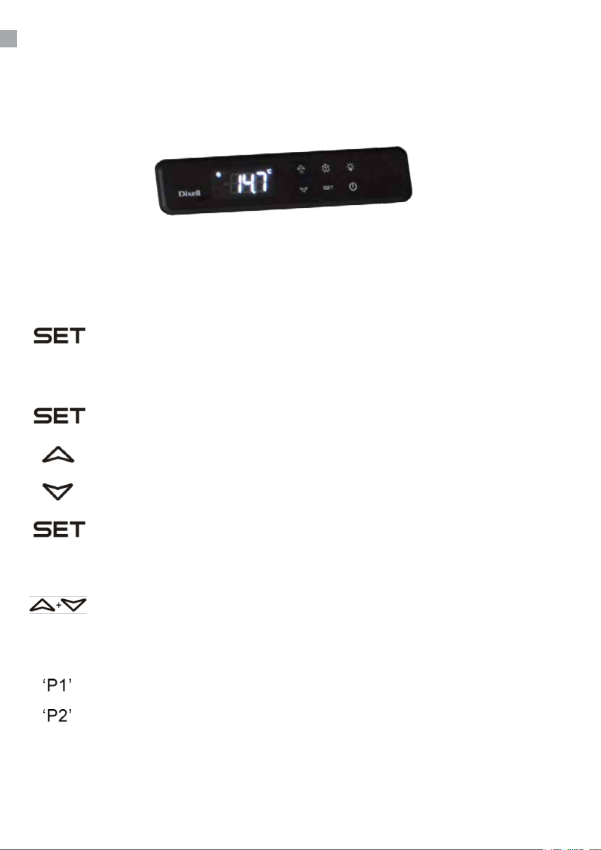
The thermostat is placed in the control panel.
The thermostat has been pre-set and in most cases it is not necessary to adjust the settings.
When turning on the cabinet the display will show the current temperature in the cabinet.
Display set temperature:
Press this key and the display will show the set temperature. Press the key again to
return to normal reading
Set new temperature:
Press this key continuously for more than 3 seconds and the display shows the set
temperature. (The ‘°C’ LED is ashing)
Press this key to increase the set temperature.
Press this key to lower the set temperature.
Press this key to save the new settings. The display will ash with the new value and
will then return to normal reading.
Keyboard lock/unlock:
Press these keys simultaneously for 5 seconds. To lock the display reads ‘PoF’.
To unlock the display reads ‘Pon’.
Alarm codes:
Flashing in the display: indicates that the cabinet sensor is defective.
Flashing in the display: indicates that the evaporator sensor is defective.
CHANGING OF PARAMETERS
See table of parameters from page 74.
Page 7

DEFROSTING
The cabinet defrosts automatically with pre-set intervals. If the door to the cabinet is opened or
the contents of the cabinet is changed frequently it may become necessary to defrost the cabinet
manually.
Pressing this key continuously for more than 3 seconds will start a manual defrosting
and then return to normal operation.
Defrosted water runs to a container placed in the compressor compartment and evaporates.
CLEANING AND MAINTENANCE
Switch o the electrical connection at the socket.
The cabinet must be periodically cleaned. Clean the external and internal surfaces of the cabinet with
a light soap solution and subsequently wipe dry.
Do not spray the appliance with direct jets of water or using high pressure appliances.
Do NOT use cleansers containing chlorine or other harsh cleansers, as these can damage the
surfaces and the internal cooling system.
Clean the condenser and the compressor compartment using a vacuum cleaner and a sti brush.
SERVICE
The cooling system is a hermetically sealed system and does not require supervision, only cleaning.
If the cabinet fails to cool, check if the reason is a power cut.
If you cannot locate the reason to the failure of the cabinet, please contact your supplier. Please
inform model and serial number of the cabinet. You can nd this information on the rating label which
is placed inside the cabinet in the top right hand side.
DISPOSAL
Disposal of the cabinet must take place in an environmentally correct way. Please note existing
regulation on disposal. There may be special requirements and conditions which must be observed.
7
Page 8

rfj_200516
Specications subject to changes without prior notication.
TEFCOLD A/S, Industrivej 25, DK-8800 Viborg © TEFCOLD A/S 2024
Page 9
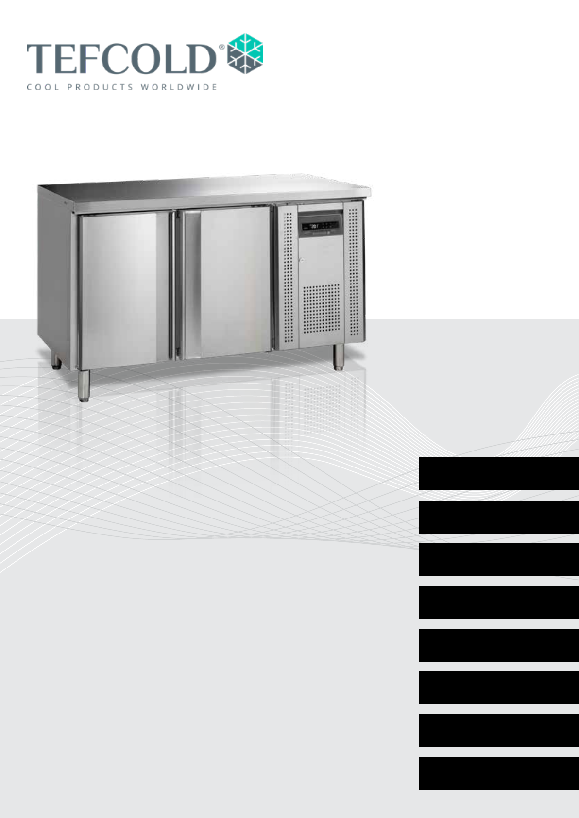
Gastro-Line Kühltheken
Betriebsanleitung
Modelle:
CK Serie
CF Serie
SK Serie
BK Serie
UC Serie
SS Serie
DE
DK
SV
FR
IT 41
ES 49
PT 57
9
17
25
33
PT Serie
RUS 65
Page 10

10
Page 11

INHALT
1.
2.
Allgemeine Information
Wichtige Sicherheitsvorschriften ......................................................................... 12
Aufstellen ............................................................................................................. 12
Anschlieβen ......................................................................................................... 13
Einschalten ........................................................................................................... 13
Temperaturregelung ............................................................................................ 14
Abtauen ............................................................................................................... 15
Reinigung und Optimierung der Energieezienz ................................................ 15
Wartung und Kundendienst .................................................................................. 15
Entsorgung .......................................................................................................... 15
Schaltpläne ........................................................................................................... 73
Thermostat Technische Bedienungsanleitung
Dixell XW20LRH .................................................................................................. 74
3.
Dixell XW60LRH .................................................................................................. 79
EPREL
EPREL data .......................................................................................................... 85
11
Page 12

WICHTIGE SICHERHEITSVORSCHRIFTEN
1. Vor Inbetriebnahme des Gerätes machen Sie sich bitte mit der Gebrauchanweisung
insbesondere der Sicherheitsvorschriften vertraut.
2. Bei Zuwiderhandlung gegen diese oder fahrlässigem Gebrauch übernimmt der Anwender des
Produktes die Haftung für eventuell dadurch entstehende Sach- sowie Personschäden.
3. Im Falle einer Störung kontaktieren Sie bitte daher umgehend Ihren Fachhändler.
4. Platzieren Sie den Schrank an einem trockenen Standort.
5. Der Schrank darf nicht in der Nähe von Hitzeabstrahlenden Geräten platziert werden.
Vermeiden Sie Standorte mit direktem Sonnenlicht.
6. Bitte denken Sie daran, dass alle elektrischen Geräte gefährlich sein können.
7. Bewahren Sie keine explosiven Stoe wie z.B. chemische Verdünnungsmittel und Benzin in
diesem Gerät auf.
8. Wir erklären, dass kein Asbest noch CFC im Aufbau verwendet worden ist.
9. Das Öl im Kompressor enthält nicht PWB.
Der Kühlschrank enthält das energieeziente und nicht ozonabbauende Kältemittel
R600a/R290. Weil R600a/R290 ein sehr brennbares Gas ist, muss unbedingt darauf
geachtet werden, dass der Kühlschrank im Transport und bei der Installation nicht
beschädigt wird. Wenn der Kühlschrank doch beschädigt wird, darf kein oenes Feuer
in der Nähe vom Schrank verwendet werden. In dem Fall darf der Schrank auch nicht
Strom zugeschlossen werden. Sorgen Sie außerdem für eine gute Entlüftung vom
Raum. Bei Zweifel kontaktieren Sie bitte sofort Ihren Lieferanten.
Wichtig!
Der Boden dieses Kühlgeräts ist für hermetisch verschlossene Behälter bestimmt, die verarbeitete
Lebensmittel enthalten (EN 16825).
AUFSTELLUNG
Der Schrank wird auf einer Holzpalette für sicheren Transport geliefert. Entfernen Sie diese und
stellen Sie den Schrank in einer geraden/waagrechten Position auf.
12
Page 13

ANSCHLIEβEN
Das Gerät hat eine Spannung von 220-240 V/50 Hz.
Der Stecker muss geerdet sein (Schuko).
Sollten Sie das Kabel ersetzen müssen, benutzen Sie unbedingt ein entsprechendes geerdetes
Kabel.
Bitte beachten Sie, dass der Anschluss lediglich durch einen erfahrenen Elektriker erfolgen darf.
Wenn der Kabel beschädigt ist sollte es bei entweder der Hersteller oder ein Service Vertreter ersetzt
werden um Gefahr zu vermeiden.
EINSCHALTEN
Es empehlt sich das Gerät vor Inbetriebnahme zu reinigen (Näheres unter „Reinigen“).
Wichtig!
Wenn der Schrank auf dem Rücken liegend geliefert ist, nehmen Sie 2 Stunden vor Einschalten.
13
Page 14
TEMPERATURREGELUNG
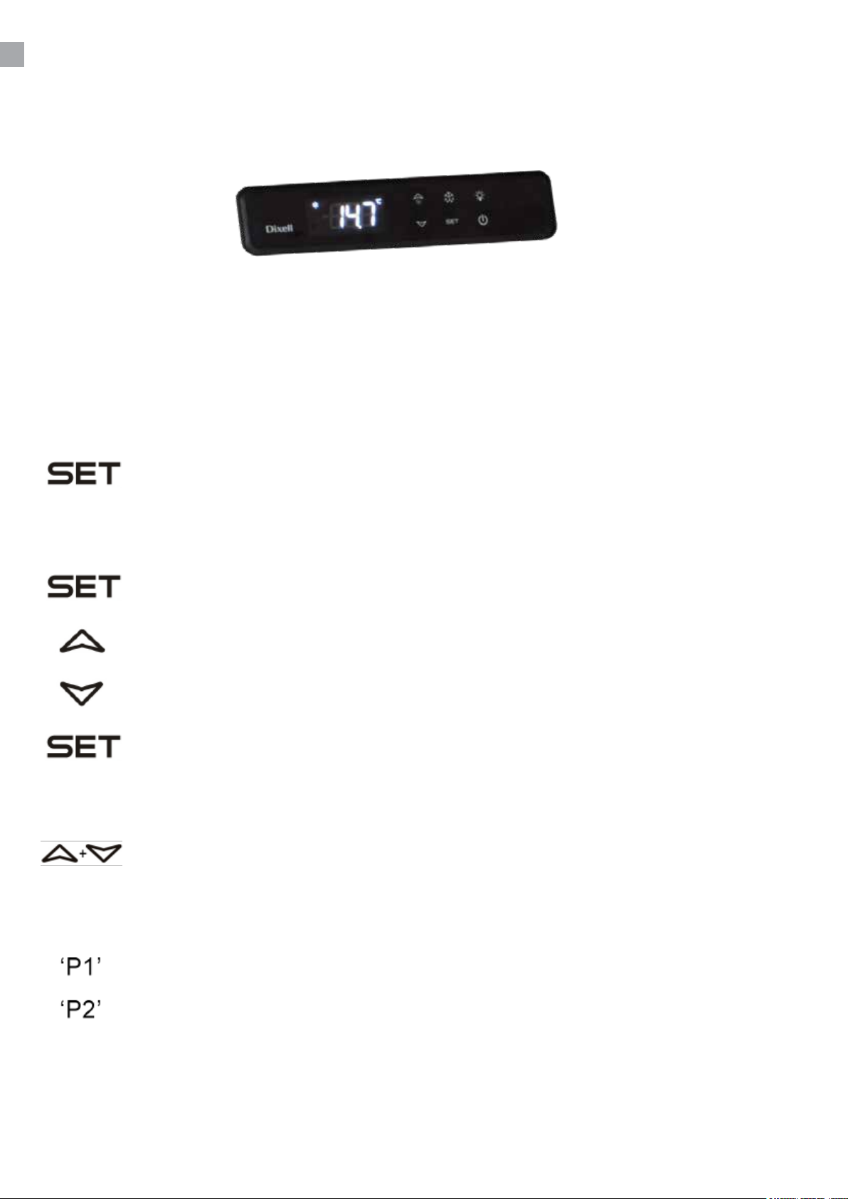
Der Thermostat benden sich in der Bodenplatte.
Der Regler ist voreingestellt für den Schrank und normalerweise es ist nicht notwendig die
Einstellung zu regulieren.
Bei Anschließen zeigt das Display die aktuelle Temperatur im Schrank.
Eingestellt Temperatur gezeigt:
Drücken Sie auf diesen Taster und Display zeigt die eingestellte Temperatur. Nochmal
drücken um normale Temperatur zu zeigen .
Neue Temperatur einstellen:
Drücken Sie auf diesen Taster mehr als 3 Sekunden und Display zeigt die eingestellt
Temperatur. (Die ‘°C’ LED blinkt)
Drücken Sie auf diesen Taster um die eingestellte Temperatur zu erhöhen.
Drücken Sie auf diesen Taster um die eingestellte Temperatur zu senken.
Drücken Sie auf diesen Taster um die neue Einstellung zu lagern. Display blinkt mit den
neuen Wert und geht zurück zu der normalen Funktion.
Tastaturschloss:
Drücken Sie gleichzeitig auf diese Tasten für 5 Sekunden um die Tastatur zu
verschliessen (Display zeigt „Pof“) oder um aufzuschliessen ( Display zeigt ’Pon’).
Störungsanzeigen:
Erscheint in Display: bedeutet das der Raumsensor defekt ist.
Erscheint in Display: bedeutet das der Verdampfersensor defekt ist.
ÄNDERUNG DER PARAMETER
Siehe Parameterübersicht vom Seite 74.
14
Page 15

ABTAUEN
Der Schrank wird in vorprogrammierten Intervallen automatisch abgetaut. Falls der Schrank mit
häugen Önungen von Tür order häuge Auswechseln von Gefriergut äußerst belastet wird es ist
vielleicht notwendig der Schrank manuell abzutauen.
Drücken Sie auf diesen Taster mehr als 3 Sekunden fängt die manuellen Abtauung
statt, und dann zu normalen Betrieb zurückkehren.
Tauwasser zur Verdampfung wird in einen Behälter im Kompressorraum abgelassen.
REINIGUNG UND OPTIMIERUNG DER
ENERGIEEFFIZIENZ
Der Schrank auf Steckdose ausschalten.
In regelmäßigen Zwischenräumen den Schrank reinigen mit mildem Geschirrspülmittel innen und
außen. Alles mit einem Tuch gut trocken.
Verwenden Sie keine säurehaltige Putz- und chemische Lösungsmittel, diese möchten Rostfraß auf
die oberächen und Innenkühlsystem verursachen.
Kondensator und das übrige Kompressorraum mit Staubsauger reinigen und eine steife Bürste.
Achten Sie darauf, dass kein Wasser im Kompressorraum und in de elektrischen Teile kommt, das
Kurzschluss verursachen kann
WARTUNG UND KUNDENDIENST
Das Kühlsystem ist ein hermetisches geschlossenes System und fordert kein Besichtigung nur
Reinigung.
Bei Ausfall der Kühlung prüfen Sie ob der Netzstecker richtig in der Stockdose ist und die Sicherung
der Stockdose in Ordnung ist.
Wenn keine Ursachen vorliegen und Sie die Störung nicht selbst beseitigen konnten, wenden Sie
sich bitte an die Kundendienststelle. Teilen Sie die Typenbezeichnung und Seriennummer mit. Diese
Informationen nden Sie auf den Typenschild in Schrank an der rechten Seite oben.
ENTSORGUNG
Wenn der Schrank ausgedient hat, muss die Entsorgung durch eine anständig umweltmäßige
Wiese vorgenommen werden. Beachten Sie die Vorschriften für Entsorgung. Es gibt z.B.
Spezialforderungen und Bedingungen zu beachten.
15
Page 16

rfj_200516
Specications subject to changes without prior notication.
TEFCOLD A/S, Industrivej 25, DK-8800 Viborg © TEFCOLD A/S 2024
Page 17
Gastro-Line Køleborde
Brugsvejledning
Modeller:
CK Serie
CF Serie
SK Serie
BK Serie
UC Serie
SS Serie
PT Serie
DK
SV
FR
IT 41
ES 49
PT 57
RUS 65
17
25
33
Page 18

18
Page 19

INDHOLD
1.
2.
Brugsvejledning
Vigtige informationer og energi besparende anbefalinger .................................. 20
Udpakning og opstilling ....................................................................................... 20
El-tilslutning ......................................................................................................... 21
Opstart ................................................................................................................. 21
Termostaten ......................................................................................................... 22
Afrimning ............................................................................................................. 23
Vedligeholdelse .................................................................................................... 23
Service ................................................................................................................. 23
Bortskaelse ........................................................................................................ 23
El-diagrammer ...................................................................................................... 73
Termostater tekniske manualer
Dixell XW20LRH .................................................................................................. 74
3.
Dixell XW60LRH .................................................................................................. 79
EPREL
EPREL data .......................................................................................................... 85
19
Page 20

VIGTIGE INFORMATIONER OG ENERGI
BESPARENDE ANBEFALINGER
1. For at få det fulde udbytte af kølemøblet, bør De læse denne brugsvejledning igennem.
2. Det er brugers ansvar at anvende kølemøblet i henhold til instruktionerne.
3. Kontakt omgående forhandleren, såfremt der opstår fejl ved kølemøblet.
4. Kølemøblet bør anbringes i et tørt og tilstrækkeligt ventileret rum.
5. Kølemøblet bør ikke placeres i nærheden af varmekilder eller direkte sollys.
6. Varme drikke og madvarer bør køles ned inden de placeres i kølemøblet.
7. Væsker bør opbevares i tildækkede beholdere for ikke at få luftfugtigheden til at stige i
kølemøblet og få køletiden til at forøges.
8. Åbne døre og skuer så kortvarigt som muligt.
9. Kontrollere at døre og skuer lukker tæt og rengør tætningslisterne jævnligt.
10. Bemærk at alle elektriske apparater kan medføre farer.
11. Opbevar ikke eksplosionsfarlige stoer, f.eks. gas, benzin, æter og lignende.
12. Der er ikke brugt asbest eller CFC i konstruktionen.
13. Olien i kompressoren indeholder ikke PCB.
20
Kølemøblet indeholder det energirigtige og ikke ozonnedbrydende kølemiddel R600a/
R290. Da R600a/R290 er en brandfarlig gasart, er det vigtigt, at kølekredsløbet ikke
beskadiges under transport og ved installering.
Hvis kølekredsløbet alligevel beskadiges, skal du undgå at bruge åben ild i nærheden
af køleskabet, ligesom der heller ikke må tilsluttes strøm til skabet. Sørg desuden for
god udluftning i rummet. Er du i tvivl, skal du kontakte din leverandør.
Vigtigt !
Bunden af dette kølemøbel er velegnet som opbevaringsareal af hermetisk lukkede beholdere med
forarbejdede fødevarer (EN 16825).
UDPAKNING OG OPSTILLING
Produktet leveres emballeret, undersøg denne for skader inden udpakning.
Page 21

EL-TILSLUTNING
Kølemøblet er beregnet for tilslutning til 220-240 V/50 Hz. Tilslutningen skal ske ved en stikkontakt,
der bør være let tilgængelig.
Dette kølemøbel skal ekstrabeskyttes ifølge stærkstrømsreglementet. Dette gælder også, selvom der
er tale om udskiftning af et eksisterende kølemøbel, der ikke har været ekstrabeskyttet. I bygninger
opført før 1. april 1975 er ekstrabeskyttelsen i orden, hvis der er installeret HFI-afbryder, som
beskytter den stikkontakt kølemøblet skal tilsluttes.
I begge disse tilfælde skal der, hvis stikkontakten er for trebenet stikprop, benyttes en trebenet
stikprop, og lederen med grøn/gul isolation skal tilsluttes jordklemmen (mærket ).
Hvis stikkontakten kun er for tobenet stikprop, benyttes en tobenet stikprop. Hvis brugeren selv
monterer denne, skal lederen med grøn/gul isolation klippes af så tæt som muligt på det sted, hvor
lederen går ind i stikproppen.
I alle andre tilfælde bør De lade en autoriseret el-installatør undersøge, hvordan De nemmest får
ekstrabeskyttet kølemøblet. Hvis De ikke har ekstrabeskyttelse i bygningen i forvejen, anbefaler
Elektricitetsrådet, at De lader el-installatøren opsætte en PFI- eller HPFI afbryder.
OPSTART
Inden kølemøblet tages i brug, anbefales det at rengøre dette, se afsnit om vedligeholdelse.
Vigtigt !
Hvis kølemøblet har ligget ned under transport, vent 2 timer før opstart.
21
Page 22
TERMOSTATEN
Termostaten er placeret i sidepanelet
Termostaten er for-programmeret så kølemøblet er klar til brug. Hvis der skal justeres i indstillinger
følg denne vejledning.
Når skabet tændes vil display vise den aktuelle temperatur i møblet.
Vis indstillet temperatur:
Tryk på denne tast og display viser den indstillede temperatur, tryk igen for at vende
tilbage til normal visning.
Indstil ny temperatur:
Tryk på denne tast i mere end 3 sec. og display viser den indstillede temperatur.
(‘°C’ LED blinker)
Tryk på denne tast for at hæve den indstillede temperatur..
Tryk på denne tast for at sænke den indstillede temperatur.
Tryk på denne tast for at gemme den nye indstilling, display blinker med den nye værdi
og vender derefter tilbage til normal visning.
Tastatur lås:
Tryk på disse 2 taster samtidigt i 5 sekunder for at låse/åbne tastaturet.
Lås tastatur (Display viser „Pof“) eller åbne tastatur ( Display viser ’Pon’).
Fejlkoder:
Blinker i display, betyder at rumføler er defekt.
Blinker i display, betyder at fordamperfæler er defekt.
ÆNDRING AF PARAMETRE
Se parameter oversigt og manualer fra side 74.
22
Page 23
AFRIMNING
Kølemøblet afrimer automatisk med forprogrammerede intervaller. Hvis møblet belastes ekstremt
med hyppige åbninger af dør eller hyppig udskiftning af varer, kan det blive nødvendigt at udføre en
manuel afrimning.
Tryk på denne tast i mere end 3 sec., dette vil starte en manuel afrimning og derefter
vende tilbage til normal drift.
Tøvand ledes ud til fordampning i en beholder, der er placeret i kompressorrum.
VEDLIGEHOLDELSE
Afbryd kølemøblet på stikkontakten.
Med passende mellemrum skal kølemøblet rengøres. Udvendig og indvendige rengøring foretages
med svag sæbeopløsning og aftørres grundigt.
Rengøringsmidler må IKKE indeholde klor, klorforbindelser eller andre aggresive midler, da de kan
forårsage tæringer på overader og på det indvendige kølesystem.
Ventilationsristen holdes bedst rent ved hjælp af en støvsuger og en stiv børste.
SERVICE
Kølesystemet er et hermetisk lukket system og kræver ikke tilsyn, kun renholdelse.
Ved svigt i kølevirkningen, undersøg om årsagen er afbrydelse i stikkontakt eller sikringsgruppe.
Kan grunden til svigt ikke ndes, må De henvende Dem til Deres leverandør. Ved al henvendelse
bedes De oplyse skabets typenavn og serienummer. Disse oplysninger ndes på typenummerskiltet
placeret indvendigt i højre side.
BORTSKAFFELSE
Når det udtjente kølemøbel skal bortskaes, skal det ske på en miljømæssig forsvarlig måde. Vær
opmærksom på reglerne for bortskaelse. Der kan være særlige krav og betingelser, der skal
overholdes.
23
Page 24

rfj_200516
Specications subject to changes without prior notication.
TEFCOLD A/S, Industrivej 25, DK-8800 Viborg © TEFCOLD A/S 2024
Page 25
Gastro-Line Kylbänker
Bruksanvisning
Modeler:
CK Serie
CF Serie
SK Serie
BK Serie
UC Serie
SS Serie
PT Serie
SV
FR
IT 41
ES 49
PT 57
RUS 65
25
33
Page 26

26
Page 27

INNEHÅL
1.
2.
Allmänna anvisningar
Viktiga anvisningar ............................................................................................. 28
Uppackning och uppställning ............................................................................... 28
Elanslutning ......................................................................................................... 29
Driftsstart .............................................................................................................. 29
Termostaten ......................................................................................................... 30
Avfrostning .......................................................................................................... 31
Underhåll och optimering av energieektivitet ...................................................... 31
Service ................................................................................................................. 31
Bortskaande ...................................................................................................... 31
Elscheman ............................................................................................................ 73
Teknisk handbok för termostat
Dixell XW20LRH .................................................................................................. 74
3.
Dixell XW60LRH .................................................................................................. 79
EPREL
EPREL data .......................................................................................................... 85
27
Page 28

VIKTIGA ANVISNINGAR
1. Läs den här bruksanvisningen så att du får bästa möjliga nytta av kylskåpet.
2. Det är användarens ansvar att använda kylskåpet enligt anvisningarna.
3. Kontakta återförsäljaren omgående om det uppstår fel på kylskåpet.
4. Kylskåpet bör placeras i ett torrt rum med god ventilation.
5. Kylskåpet bör inte placeras i närheten av värmekällor eller i direkt solljus.
6. Observera att alla elektriska apparater kan innebära fara.
7. Förvara inte explosionsfarliga ämnen som t.ex. gas, bensin eter eller liknande.
8. Ingen asbest och inga freoner (CFC) har använts vid konstruktionen.
9. Oljan i kompressorn innehåller inte PCB.
Kylen innehåller det energigodkända och icke ozonnedbrytande kylmedlet R600a/
R290. R600a/R290 är en brandfarlig typ av gas och det är därför viktigt att
kylkretsloppet inte skadas under transport och installering.
Om kylkretsloppet trots detta skadas ska man undvika att använda öppen eld i
närheten av kylen och enheten får heller inte anslutas till strömuttag. Sörj dessutom för
god ventilation i rummet. Vid tveksamhet: kontakta din leverantör.
Viktigt !
Basen i detta kylskåp är konstruerad för hermetiskt förseglade behållare som innehåller färdiglagad
mat (EN 16825).
UPPACKNING OCH UPPSTÄLLNING
Kontrollera att det inte nns några skador på emballaget före uppackning.
28
Page 29

ELANSLUTNING
Kylskåpet är beräknat för anslutning till 230 V/50 Hz. Anslutningen ska göras med en stickkontakt
som bör vara lätt åtkomlig.
Detta kylskåp ska extraskyddas enligt starkströmsbestämmelserna. Detta gäller också även vid
utbyte av ett bentligt kylskåp som inte haft sådant extraskydd.
Använd alltid jordade stickkontakter med tre ledare. Kabelledaren med grön/gul isolering ska jordas
(märkt ).
I alla övriga fall hänvisas till behörig elektriker som kan informera om hur apparaten ges extra skydd.
Om byggnaden saknar extra skydd rekommenderar vi att en elektriker installerar en jordfelsbrytare
(PFI eller HPFI).
DRIFTSSTART
Innan kylskåpet tas i bruk ska det rengöras. Se avsnittet om underhåll.
Viktigt !
Om kylskåpet har legat ner under transporten ska du vänta två (2) timmar innan det startas.
29
Page 30
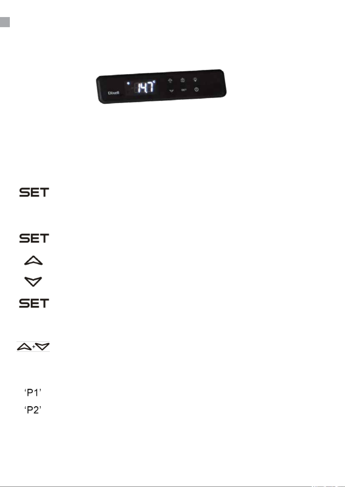
TERMOSTATEN
Termostaten är placerad i teknik dörr.
Termostaten är förprogrammerad för skåpet, och oftast behöver inga inställningar justeras.
När skåpet startas kommer displayen att visa den aktuella temperaturen i skåpet.
Visa inställd temperatur:
Tryck på den här knappen så visar displayen den inställda temperaturen. Tryck på nytt
för att återvända till normal visning.
Ställa in ny temperatur:
Tryck på den här knappen i minst tre (3) sekunder så visar displayen den inställda
temperaturen. (‘°C’ LED blinkar)
Tryck på den här knappen för att höja temperaturen.
Tryck på den här knappen för att sänka temperaturen.
Tryck på den här knappen för att spara den nya inställningen. Det nya värdet blinkar på
displayen och därefter återgår displayen till normal visning.
Knapplås:
Tryck på dessa knappar samtidigt i fem (5) sek för att låsa, displayen visar ’Pof’ om
du ska låsa upp visar displayen ’Pon’.
Felkoder:
Blinkande display betyder att skåpets rumstemperaturgivare är defekt.
Blinkande display betyder att skåpets förångningsgivare är defekt.
ÄNDRA PARAMETRARNA
Se parameteröversikt på sida 74.
30
Page 31

AVFROSTNING
Skåpet avfrostas automatiskt enligt förprogrammerade intervall. Om skåpet belastas extremt mycket
med återkommande öppningar av dörren eller återkommande byte av innehållet kan en manuell
avfrostning bli nödvändig.
Tryck på den här knappen i minst tre (3) sekunder. Då startar den manuella
avfrostningen och därefter återgår skåpet till normal drift.
Smältvatten leds ut till förångning i en behållare som sitter i kompressorutrymmet.
UNDERHÅLL
Bryt strömmen till kylskåpet genom att dra ut stickkontakten.
Kylskåpet ska rengöras med lämpliga mellanrum. Utvändig och invändig rengöring ska utföras med
en svag tvållösning (milt diskmedel) och därefter ska skåpet torkas av noggrant.
Rengöringsmedel får INTE innehålla klor, klorföreningar eller andra aggressiva medel eftersom de
kan orsaka skador på ytorna och på det interna kylsystemet.
Ventilationsgallret ska rengöras med dammsugare och en styv borste.
SERVICE
Kylsystemet är ett hermetiskt slutet system och kräver ingen tillsyn – endast rengörning.
Vid dålig kylverkan: kontrollera först om orsaken är ett avbrott i stickkontakten eller proppskåpet.
Kontakta återförsäljaren om det inte går att lokalisera felet. Vi ber dig alltid uppge skåpets
typbeteckning och serienummer vid alla kontakter med oss. Informationen sitter på skåpets insida, på
märkskylten överst på högra sidan.
BORTSKAFFANDE
Ett uttjänt kylskåp måste bortskaas på ett miljömässigt försvarbart sätt. Var uppmärksam på vilka
regler som gäller för bortskaande. Det kan nnas särskilda krav och bestämmelser som måste
följas.
31
Page 32

rfj_200516
Specications subject to changes without prior notication.
TEFCOLD A/S, Industrivej 25, DK-8800 Viborg © TEFCOLD A/S 2024
Page 33
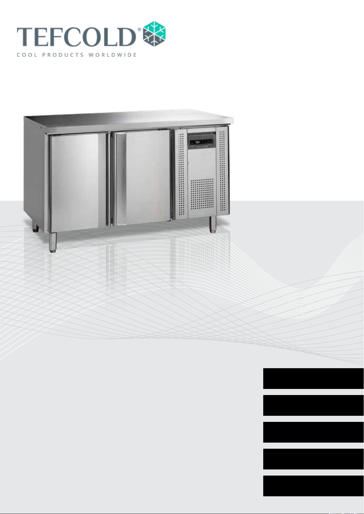
Gastro-Line Comptoirs
Mode d’ emploi
Model:
CK Série
CF Série
SK Série
BK Série
UC Série
SS Série
PT Série
FR 33
IT 41
ES 49
PT 57
RUS 65
Page 34

34
Page 35

SOMMAIRE
1.
2.
Informations générales
Instructions importantes ...................................................................................... 36
Désassemblage et mise en place ........................................................................ 36
Branchement électrique ....................................................................................... 37
Démarrage............................................................................................................ 37
Thermostat .......................................................................................................... 38
Dégivrage ............................................................................................................ 39
Maintenance et optimisation de l’ecacité énergétique ....................................... 39
Service ................................................................................................................. 39
Élimination ........................................................................................................... 39
Schéma électrique ................................................................................................ 73
Manuel technique du thermostat
Dixell XW20LRH .................................................................................................. 74
3.
Dixell XW60LRH .................................................................................................. 79
EPREL
EPREL data .......................................................................................................... 85
35
Page 36

INSTRUCTIONS IMPORTANTES
1. Avant d’utiliser votre armoire, nous vous recommandons de lire ce mode d’emploi dans son
entier.
2. C’est la responsabilité de l’utilisateur de manier l’appareil selon les instructions données.
3. Contacter votre revendeur immédiatement en cas de défauts de fonctionnement de l’armoire.
4. L’armoire doit être placée dans un endroit sec et ventilé.
5. L’armoire ne doit pas être exposée aux rayons du soleil ou à tout autre source de chaleur.
6. N’oublier pas que tous les appareils électriques sont des sources de danger potentiel.
7. Ne conserver pas et n’utilisez pas des produits qui pourraient provoquer des explosions ou qui
sont inammables, tels que gaz, briquets, essence, éther etc. dans l’armoire.
8. Aucune asbeste ou CFC est utilisée dans la construction de l’armoire.
9. L’huile dans le compresseur ne contient pas de PCB.
POUR LES ARMOIRES AVEC RÉFRIGÉRANT R290/R600a!
Ce refroissseur contient un réfrigérant inammable; assurez un endroit bien ventilé
autour de l’armoire. N’utilisez pas des outils mécaniques pour le dégivrage; cela peut
causer des fuites dans le système de refroidissement interne. N’utilisez pas des outils
électrique á l’intérieur de l’armoire.
Chaque réparation de ce réfroidisseur doit être eectué par un réparateur professionel.
(EN 60335-2-89: 2010)
Important !
La base de ce réfrigérateur est conçue pour les récipients hermétiques contenant des aliments
transformés (EN 16825).
DÉSASSEMBLAGE ET MISE EN PLACE
L’armoire est livrée avec une palette en bois an de l’assurer pendant le transport. Enlever la palette
et placer l’armoire d’une position verticale. Les surfaces extérieures sont équippées d’un lm pelable,
qu’il faut enlever avant la mise en place.
Lors de la mise en place, l’armoire doit être de niveau, ce qui s’obtient aisément grâce aux pieds
réglables. (Quelques armoires sont livrées avec roulettes au lieu de pieds réglables).
36
Page 37

BRANCHEMENT ÉLECTRIQUE
L’armoire doit être branchée par une prise d’un accès facile avec la tension de 230 V/50 Hz.
Les installations électriques doivent être eectués par un électricien spécialisé.
DÉMARRAGE
Avant d’utiliser votre armoire, nous vous recommandons de la nettoyer, voir la section « entretien ».
Important !
Si l’armoire a été transportée aux horizontal, il faut attendre 2 heures après l’installation pour
démarrer l’appareil.
37
Page 38
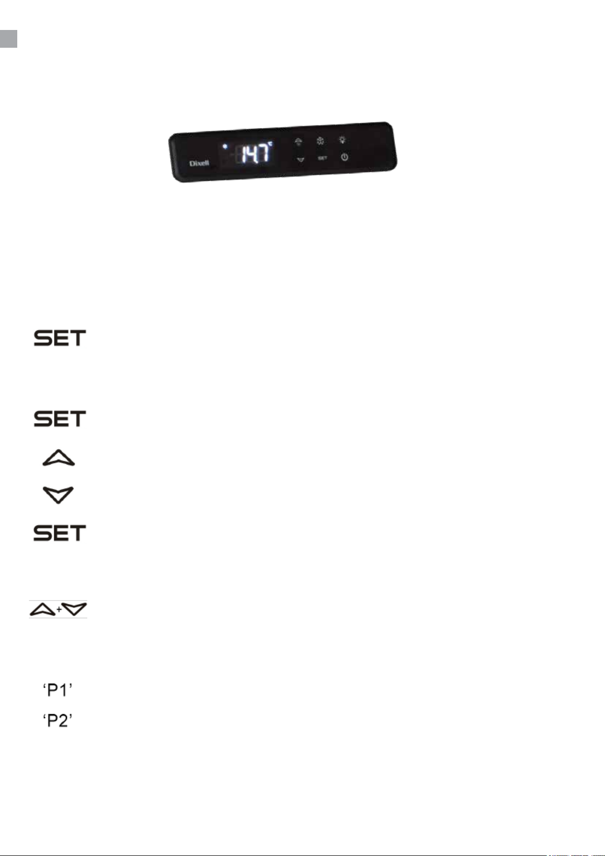
THERMOSTAT
Le thermostat est placé dans le panneau de contrôle .
Il est préprogrammé pour l’armoire ; dans la plupart des cas il est donc inutile de le régler.
Quand l’armoire est allumée, l’acheur va montrer la température actuelle à l’intérieur de l’armoire.
Montrer la température réglée:
Presser ce bouton et l’acheur montre la température réglée, presser encore une fois
pour retourner à l’indication normale.
Régler la nouvelle température:
Presser ce bouton pendant plus de 3 secondes, et l’acheur montre la température
réglée. (Le symbole ‘°C’ clignote)
Presser ce bouton pour augmenter la température réglée.
Presser ce bouton pour baisser la température réglée.
Presser ce bouton pour garder le nouveau réglage, l’acheur clignote avec la nouvelle
température, puis il retourne à l’indication normale.
Serrure de clavier :
Presser ces boutons simultanément pendant 5 secondes pour bloquer, l’acheur
montre « Pof » ou pour débloquer, l’acheur montre « Pon ».
Codes d’érreurs:
Clignotant dans l’acheur signie que la sonde du thermostat est défectueuse.
Clignotant dans l’acheur signie que la sonde de l’évaporateur est défectueuse.
CHANGEMENT DES PARAMÈTRES
Voir table des paramètres page 74.
38
Page 39

DÉGIVRAGE
L’armoire se dégivre automatiquement avec des intervalles programmés. Si l’armoire est exposée
aux ouvertures de la porte ou remplacements des marchandises très fréquents, un dégivrage manuel
peut être nécessaire.
Presser ce bouton pendant plus de 3 secondes ; cela va lancer un dégivrage manuel et
après retourner au fonctionnement normal.
L’eau de dégivrage est évacuée et s’évapore dans un récipient placé dans le compartiment
compresseur.
ENTRETIEN
Débrancher l’armoire pendant le nettoyage.
Le nettoyage de l’intérieur et l’extérieur de l’armoire doit être eectué par intervalles convenables
à l’aide d’un produit à vaisselle non parfumé. L’armoire doit être essuyée minutieusement après le
nettoyage. L’extérieur peut être maintenu avec un produit (creme, huile) pour l’inox.
N’utiliser pas des produits à vaisselle chlorés ou d’autres produits aggrésifs, parce qu’ils pourraient
causer la corrosion de l’acier inox et du système frigorique interne.
SERVICE
Le système frigorique est étanche à l’air ; il n’est donc pas nécesssaire de le surveiller, il sut de le
nettoyer.
Si l’armoire ne rafraîchit pas, vérier que la che est bien enfoncée, que la fusible est intact et qu’il
n’y a pas de coupure de courant.
Si vous ne pouvez pas trouver la cause du défaut, contacter votre revendeur. Informer la référence
et le numéro de série de l’armoire, ce que vous pouvez trouver à l’intérieur de l’armoire sur l’étiquette
placée en haut à droite.
ÉLIMINATION
Quand l’armoire usée doit être éliminée, il doit se passer d’une manière qui ne compromet pas
l’environnement. Veuillez prendre note des règles d’élimination et examiner s’il existe des demandes
et conditions spéciques qu’il faut respecter.
39
Page 40

rfj_200516
Specications subject to changes without prior notication.
TEFCOLD A/S, Industrivej 25, DK-8800 Viborg © TEFCOLD A/S 2024
Page 41
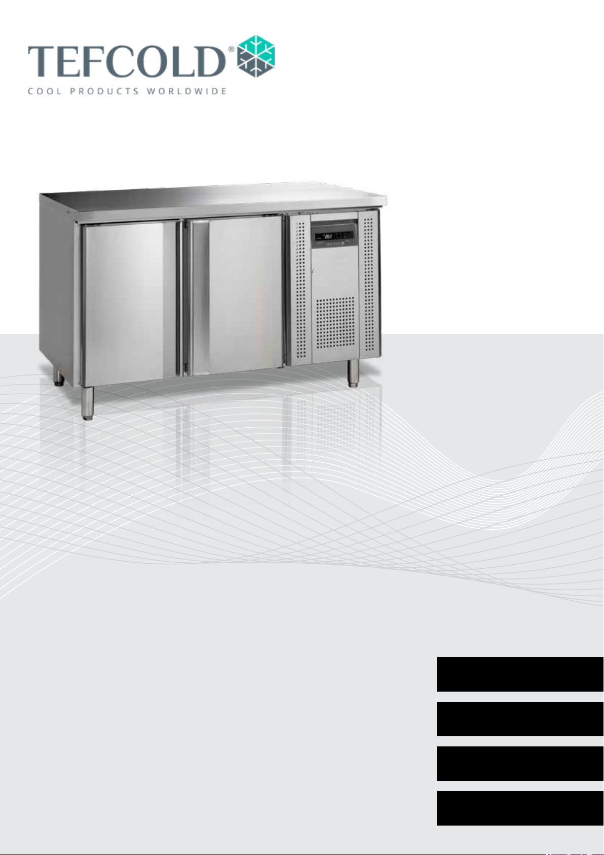
Gastro-Line Banconi
Manuale d’uso
Modello:
CK Serie
CF Serie
SK Serie
BK Serie
UC Serie
SS Serie
PT Serie
IT 41
ES 49
PT 57
RUS 65
Page 42

42
Page 43

SOMMARIO
1.
2.
Informazioni generali
Importanti nozioni di sicurezza ............................................................................. 36
Rimozione dell’imballaggio e installazione .......................................................... 36
Collegamenti elettrici ............................................................................................ 37
Inizializzazione dell’armadio ................................................................................. 37
Termostato ........................................................................................................... 38
Sbrinamento ........................................................................................................ 39
Manutenzione e ottimizzazione dell’ecienza energetica .................................... 39
Assistenza ........................................................................................................... 39
Smaltimento.......................................................................................................... 39
Schema elettrico ................................................................................................... 73
Manuel technique du thermostat
Dixell XW20LRH .................................................................................................. 74
3.
Dixell XW60LRH .................................................................................................. 79
EPREL
EPREL data .......................................................................................................... 85
43
Page 44

INSTRUCCIONES DE SEGURIDAD IMPORTANTES
1. Para obtener el máximo rendimiento del armario, recomendamos la lectura de este manual de
instrucciones.
2. Es responsabilidad del usuario utilizar el electrodoméstico de acuerdo con las instrucciones
facilitadas.
3. Póngase en contacto inmediatamente con su concesionario en caso de cualquier anomalía.
4. Coloque el armario en un lugar seco y ventilado.
5. Mantenga el armario alejado de fuentes de mucho calor y no lo exponga a la luz solar directa.
6. Tenga siempre en cuenta que todos los dispositivos eléctricos pueden ser el origen de
peligros potenciales.
7. No almacene materiales inamables como disolvente, gasolina, etc., en el armario.
8. Declaramos que no se ha usado amianto ni CFC en su construcción.
9. El aceite del compresor no contiene PCB.
SOLO PER APPARECCHI CON REFRIGERANTE R290/R600a!
Questo apparecchio contiene un refrigerante inammabile: assicurarsi che vi sia una
buona ventilazione intorno all’apparecchio. Non utilizzare dispositivi meccanici in fase
di scongelamento per evitare perdite del sistema di rareddamento. Non utilizzare
dispositivi elettrici all’interno del vano di conservazione refrigerato.
Qualsiasi riparazione dell’apparecchio deve essere svolta da un tecnico qualicato
(EN 60335-2-89: 2010).
Importante
La base di questo frigorifero è stata progettata per contenitori a chiusura ermetica contenenti cibi
pronti (EN 16825).
DESEMBALAJE E INSTALACIÓN
Retire el palet de madera y el embalaje. Las supercies exteriores llevan una lámina de protección
que se debe retirar antes de la instalación.
44
Page 45

COLLEGAMENTI ELETTRICI
L’apparecchio è adatto a 230 V/50 Hz. Il collegamento deve essere eettuato attraverso una presa
accessibile.
L’apparecchio deve essere dotato di protezione extra in base alle norme relative alla potenza. Lo
stesso è previsto anche qualora venga sostituito un apparecchio senza protezione extra.
Utilizzare sempre una spina a 3 poli. Il lo con isolamento verde/giallo deve essere messo a terra
(marcatura).
In tutti gli altri casi un elettricista autorizzato sarà in grado di indicarvi come dare maggiore protezione
all’apparecchio. Qualora l’edicio non disponga di protezione extra, l’ente Board of Electricity
suggerisce l’installazione di un interruttore PFI o HPFI da parte di un elettricista (interruttore di
contatto).
PUESTA EN MARCHA DEL APARATO
Antes del uso, recomendamos limpiar el armario; remítase a la sección sobre mantenimiento y
limpieza.
Importante
Si el armario se ha colocado en posición vertical durante el transporte, espere 2 horas antes de
ponerlo en marcha.
45
Page 46
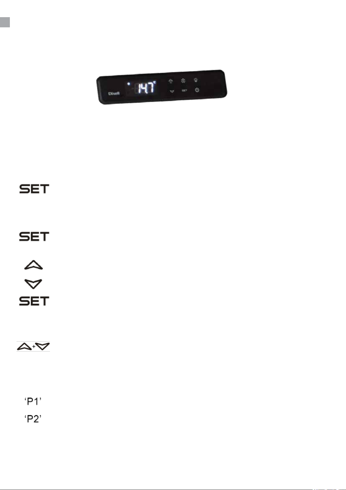
TERMOSTATO
El termostato se coloca en el panel inferior
El termostato ya está programado para este aparato. En la mayoria de los casos, no es necesario
ajustar las posiciones.
Al encender el aparato, el display/pantalla mostrará la temperatura actual en el aparato.
Para indicar temperatura:
Apriete esta tecla y la pantalla mostrará la temperatura ja. Apriete la tecla otra vez
para normalizar la lectura.
Cambio a nueva temperatura:
Apriete esta tecla, más de 3 segundos, la pantalla mostrará la temperatura ja.
(Il ‘°C’ LED lampeggia)
Apriete esta tecla para aumentar la temperatura ja.
Apriete esta tecla para bajar la temperatura ja.
Apriete esta tecla para guardar la nueva posición. La pantalla destellará con el nuevo
valor, y después volverá a la lectura normal.
Serrure de clavier :
Presser ces boutons simultanément pendant 5 secondes pour bloquer, l’acheur
montre « Pof » ou pour débloquer, l’acheur montre « Pon ».
Codigos de alarma:
Lampeggiante sul display: indica che la sonda nel frigorifero è difettosa.
Lampeggiante sul display: indica che la sonda dell’evaporatore è difettosa.
CAMBIO DEI PARAMETRI
Vedi elenco dei parametri a pag. 74.
46
Page 47

DESCONGELACIÓN
El aparato descongela automáticamente con intervalos jos programados. Si la puerta del aparato
está abierta o el contenido del aparato se cambia con frecuencia, puede llegar a ser necesario
descongelar el aparato manualmente.
Apriete esta tecla continuamente, más de 3 segundos, esto activará una escongelación
manual, y después volverá a operar normalmente.
El agua de la descongelación circula para su evaporación a un contenedor, que está situado en el
compartimento del compresor.
MANTENIMIENTO Y LIMPIEZA
Desenchufe el refrigerador por la toma de corriente.
El armario se debe limpiar periódicamente. Limpie las supercies externas e internas del armario con
una solución jabonosa ligera y séquelas después con un trapo.
NO use productos de limpieza que contengan cloro u otros productos abrasivos, puesto que pueden
dañar las supercies y el sistema de refrigeración interno.
Limpie el compartimento del condensador y del compresor con un aspirador y un cepillo rígido.
SERVICIO
El sistema de refrigeración es un sistema sellado herméticamente que no requiere supervisión, solo
limpieza.
Si el armario no enfría, compruebe si el motivo es un corte de suministro eléctrico.
Si no puede encontrar el motivo de la avería del armario, póngase en contacto con su proveedor.
Indique el modelo y el número de serie del armario. Puede encontrar dicha información en la etiqueta
de características situada en el interior del armario, en el lado superior derecho.
ELIMINACIÓN
El desechado del armario se debe realizar de forma respetuosa con el medio ambiente. Tenga en
cuenta la normativa existente en cuanto a residuos. Es posible que haya requisitos y condiciones
especiales que deban cumplirse.
47
Page 48

rfj_200516
Specications subject to changes without prior notication.
TEFCOLD A/S, Industrivej 25, DK-8800 Viborg © TEFCOLD A/S 2024
Page 49
Gastro-Line Mesas frías
Manual del usuario
Modelos:
CK Serie
CF Serie
SK Serie
BK Serie
UC Serie
SS Serie
PT Serie
ES 49
PT 57
RUS 65
Page 50

50
Page 51

SOMMARIO
1.
2.
Información general
Importantes instrucciones de seguridad ............................................................... 52
Desembalaje e instalación.................................................................................... 52
Conexión eléctrica ................................................................................................ 53
Puesta en marcha del aparato ............................................................................. 53
Termostato ........................................................................................................... 54
Descongelación .................................................................................................... 55
Mantenimiento y optimización de la eciencia energética ................................... 55
Servicio técnico .................................................................................................... 55
Como deshacerse del aparato ............................................................................. 55
Diagrama de cableado ......................................................................................... 73
Manual técnico para el termostato
Dixell XW20LRH .................................................................................................. 74
3.
Dixell XW60LRH .................................................................................................. 79
EPREL
EPREL data .......................................................................................................... 85
51
Page 52

IMPORTANTES INSTRUCCIONES DE
SEGURIDAD
1. Para obtener el uso completo y adecuado del aparato, recomendamos leer este manual de
instrucciones.
2. Es responsabilidad del usuario el manejo adecuado del aparato, de acuerdo con las
instrucciones dadas.
3. Contacte a su comerciante inmediatamente en caso de cualquier funcionamiento defectuoso.
4. Coloque el aparato en un lugar seco y ventilado.
5. Mantenga el aparato totalmente alejado de cualquier fuente de calor y no lo exponga a la luz
directa del sol.
6. Tenga siempre presente que todo dispositivo eléctrico es una fuente potencial de peligro.
7. No almacene material inammable tal como gas, gasolina, éter ó similares en el aparato.
8. No ha sido utilizado ningún asbesto ni CFC en la construcción.
9. El aceite en el compresor no contiene TCI.
¡SOLO PARA LOS MODELOS QUE INCORPOREN REFRIGERANTE R290/R600a!
Este electrodoméstico contiene un refrigerante inamable. Por lo tanto, asegúrese de
disponer de una buena ventilación a su alrededor. No utilice dispositivos mecánicos
para descongelar el electrodoméstico, ya que podría causar fugas en el sistema
de refrigeración.No utilice aparatos eléctricos en el interior del compartimento de
almacenamiento refrigerado.
Deje cualquier reparación del electrodoméstico en manos de un técnico cualicado
(EN 60335-2-89: 2010).
Importante !
La base de este refrigerador está diseñada para recipientes herméticamente sellados que
contienen alimentos procesados (EN 16825).
DESEMBALAJE E INSTALACIÓN
El aparato se entrega embalado y en un palet, desembálelo. Las supercies exteriores están
forradas con un plástico protector, quítelo antes de hacer la instalación.
52
Page 53

CONEXIÓN ELÉCTRICA
Este electrodoméstico está diseñado para su uso a 230 V/50 Hz. Debe enchufarse a una toma de
corriente accesible.
Este electrodoméstico debe disponer de una protección adicional de acuerdo con las normativas
sobre electricidad. Esto es aplicable también en el caso de que reemplace una unidad existente que
no disponga de protección adicional.
Use siempre un enchufe de tres clavijas. El hilo con aislante verde/amarillo debe conectarse a tierra
(con marca ).
En todos los demás casos, un electricista autorizado le informará sobre cómo obtener la protección
adicional para el electrodoméstico. En caso de el edicio no disponga de protección adicional, las
autoridades recomiendan que un electricista instale un interruptor PFI o HPFI (disyuntor).
PUESTA EN MARCHA DEL APARATO
Antes de su uso, recomendamos que el aparato se limpie, vea la sección de mantenimiento y
limpieza
Importante !
Si el aparato ha sido colocado horizontalmente durante su transporte, espere, por favor, 2 horas
antes de la puesta en marcha del aparato.
53
Page 54
TERMOSTATO
El termostato está colocado en el tablero de control.
El termostato ya está programado para este aparato. En la mayoria de los casos, no es necesario
ajustar las posiciones.
Al encender el aparato, el display/pantalla mostrará la temperatura actual en el aparato.
Para indicar temperatura:
Apriete esta tecla y la pantalla mostrará la temperatura ja. Apriete la tecla otra vez
para normalizar la lectura.
Cambio a nueva temperatura:
Apriete esta tecla, más de 3 segundos, la pantalla mostrará la temperatura ja.
Apriete esta tecla para aumentar la temperatura ja.
Apriete esta tecla para bajar la temperatura ja.
Apriete esta tecla para guardar la nueva posición. La pantalla destellará con el nuevo
valor, y después volverá a la lectura normal.
Cierre del teclado:
Para cerrar o activar el teclado, apriete estas teclas simultáneamente durante
5 segundos. (Para cerrar, la pantalla muestra ‘POF’, para activar, la pantalla muestra
‘PON’)
Codigos de alarma:
Destellando en la pantalla, indica que el sensor del aparato está defectuoso.
Destellando en la pantalla, indica que el sensor de evaporación está defectuoso.
CAMBIO DE PARÁMETROS
Vea lista de parámetros en la página 74.
54
Page 55

DESCONGELACIÓN
El aparato descongela automáticamente con intervalos jos programados. Si la puerta del aparato
está abierta o el contenido del aparato se cambia con frecuencia, puede llegar a ser necesario
descongelar el aparato manualmente.
Apriete esta tecla continuamente, más de 3 segundos, esto activará una
descongelación manual, y después volverá a operar normalmente.
El agua de la descongelación circula para su evaporación a un contenedor, que está situado en el
compartimento del compresor.
MANTENIMIENTO Y OPTIMIZACIÓN DE LA
EFICIENCIA ENERGÉTICA
Apague el aparato desde el enchufe.
El aparato debe ser limpiado periódicamente. Limpie las supercies externas e internas del aparato
con una solución ligera de jabón, y seque bien. Las supercies externas pueden mantenerse limpias
con un aceite especial para acero.
No utilice limpiadores que contienen cloro u otros productos agresivos, pues pueden dañar las
supercies inoxidables del acero y el sistema interior de refrigeración.
Limpie el condensador y el compartimento del compresor con la ayuda de un aspirador y un cepillo
duro.
No riegue con una manguera el compartimento del compresor, ya que el agua puede causar
cortocircuitos y daño en las partes eléctricas.
SERVICIO TÉCNICO
El sistema de refrigeración es un sistema herméticamente sellado, y no requiere supervisión, sólo
limpieza.
Si el aparato falla en la refrigeración, verique que la razón no sea un apagón, bien desde el enchufe
o de los plomos.
Si no puede localizar la razón del fallo del aparato, contacte, por favor, a su suministrador.
Informe, por favor, del modelo y el número de serie del aparato.Usted puede encontrar esta
información en la etiqueta que está colocada dentro del aparato arriba, a mano derecha.
COMO DESHACERSE DEL APARATO
Cuando se tenga que deshacer del aparato, deberá hacerlo teniendo en cuenta las normas al
respecto. Puede que haya unas exigencias y condiciones que se deban cumplir.
55
Page 56

rfj_200516
Specications subject to changes without prior notication.
TEFCOLD A/S, Industrivej 25, DK-8800 Viborg © TEFCOLD A/S 2024
Page 57
Gastro-Line Mesas de refrigeração
Manual do usuário
Modelos:
CK Serie
CF Serie
SK Serie
BK Serie
UC Serie
SS Serie
PT Serie
PT 57
RUS 65
Page 58

58
Page 59

ÍNDICE
1.
2.
Información general
Instruções importantes de segurança .................................................................. 60
Desembalagem e instalação ................................................................................ 60
Ligações Eléctricas............................................................................................... 61
Arranque da arca .................................................................................................. 61
Termostato ........................................................................................................... 62
Descongelamento................................................................................................. 63
Manutenção e otimização de eciência energética .............................................. 63
Assistência Técnica .............................................................................................. 63
Eliminação ............................................................................................................ 63
Diagrama de ação .............................................................................................. 73
Manual técnico para termostato
Dixell XW20LRH .................................................................................................. 74
3.
Dixell XW60LRH .................................................................................................. 79
EPREL
EPREL data .......................................................................................................... 85
59
Page 60

INSTRUÇÕES IMPORTANTES DE SEGURANÇA
1. Para se obter uma utilização plena desta arca vertical, recomendamos-lhe que leia este
manual de instruções.
2. A utilização do aparelho de acordo com as instruções fornecidas é da inteira responsabilidade
do utilizador.
3. Contacte imediatamente o distribuidor em caso de avarias.
4. Coloque a máquina num local seco e ventilado.
5. Mantenha o aparelho afastado de fontes de calor intenso e não o exponha a luz solar directa.
6. Tenha sempre presente que qualquer dispositivo eléctrico é uma fonte de perigo potencial.
7. Não armazene na arca quaisquer materiais inamáveis, como diluente, gasolina, etc.
8. Declara-se que não foi usado amianto ou CFC na construção deste aparelho.
9. O óleo no compressor não contém PCB.
APENAS PARA EQUIPAMENTOS COM REFRIGERANTE R290/R600a!
Este equipamento contém um agente refrigerante inamável. Por isso, certique-se
de que existe boa ventilação em torno do mesmo. Não utilize dispositivos mecânicos
quando descongelar, pois pode provocar fugas no sistema de refrigeração. Não utilize
equipamentos eléctricos no interior do compartimento de arrumação refrigerado.
Todos trabalhos de reparação no aparelho devem ser realizados por um técnico
qualicado (EN 60335-2-89: 2010).
Importante
A base deste frigoríco foi concebida para recipientes hermeticamente fechados contendo
alimentos processados (EN 16825).
DESEMBALAGEM E INSTALAÇÃO
Retire el palet de madera y el embalaje. Las supercies exteriores llevan una lámina de protección
que se debe retirar antes de la instalación.
Para garantir o correcto funcionamento da arca, é importante que esta esteja nivelada. Se a arca
tiver pés, estes podem ser ajustados.
60
Page 61

LIGAÇÕES ELÉCTRICAS
A arca funciona a 230 V/50 Hz.
A tomada de parede deverá estar facilmente acessível.
Todas as ligações à terra estipuladas pelas autoridades eléctricas locais deverão ser observadas.
A cha da arca e a tomada de parede deverão fornecer a ligação à terra adequada. Se houver
qualquer dúvida, contacte o distribuidor local ou um electricista qualicado.
As principais ligações eléctricas deverão ser executadas por electricistas credenciados.
ARRANQUE DA ARCA
Antes de utilizá-la, recomendamos que a arca seja limpa; consulte a secção sobre manutenção e
limpeza.
Importante
Se a arca tiver sido colocada na vertical durante o transporte, aguarde duas horas até ligá-la.
61
Page 62
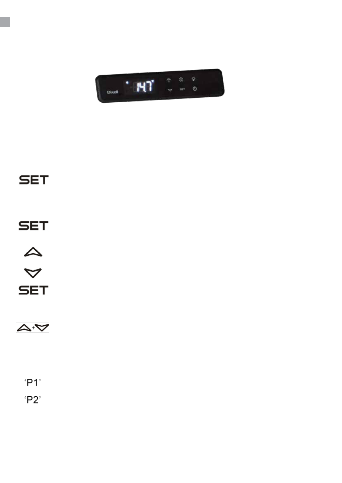
TERMÓSTATO
O termóstato encontra-se no painel de controlo.
O termóstato foi pré-regulado e, na maioria dos casos, não é necessário qualquer ajuste.
Quando a arca é ligada, o visor irá exibir a temperatura actual na câmara.
Exibir a temperatura denida:
Pressione este botão e o visor vermelho irá exibir, piscando, a temperatura denida.
Prima a tecla novamente para regressar à leitura normal.
Denir uma nova temperatura:
Pressione este botão for premido continuamente durante mais de 3 segundos, e o visor
vermelho irá exibir a temperatura denida.
Pressione este botão para aumentar a temperatura denida.
Pressione este botão para diminuir a temperatura denida.
Pressione este botão para guardar o novo parâmetro. O visor irá exibir o novo valor a
piscar e gressará à leitura normal.
Bloqueio do teclado :
Para bloquear ou desbloquear o teclado, prima estas teclas simultaneamente durante
cerca de 5 segundos (para bloquear, o visor exibe “Pof”, para desbloquear, o visor
exibe “Pon”).
Códigos de Alarme:
A piscar no visor: indica que o sensor da arca tem uma anomalia.
A piscar no visor: indica que o evaporador da arca tem uma anomalia.
ALTERAÇÃO DE PARÂMETROS
Consulte a tabela de parâmetros na página 74.
62
Page 63

DESCONGELAMENTO
A arca descongela automaticamente em intervalos pré-denidos. Se houver frequentes aberturas da
porta da arca ou mudanças do conteúdo, poderá ser necessário descongelar a arca manualmente.
Se este botão for premido continuamente durante mais de 3 segundos, dá-se início à
descongelação manual e depois regressará ao funcionamento normal.
A água daí resultante é recolhida num receptáculo colocado no compartimento do compressor e
depois evapora.
MANUTENÇÃO E OTIMIZAÇÃO DE
EFICIÊNCIA ENERGÉTICA
Desligue a arca da tomada de parede.
A arca deve ser limpa periodicamente. Limpe as superfícies interna e externa da arca com
uma solução ligeiramente ensaboada e seque de seguida. As superfícies externas poderão ser
conservadas com um óleo de máquina.
NÃO utilize produtos de limpeza que contenham cloro ou produtos abrasivos pois poderão danicar
as superfícies de aço inoxidável e o sistema de arrefecimento interno.
Limpe o condensador e o compartimento do compressor utilizando um aspirador e uma escova de
cerdas duras.
NÃO lave à mangueira o compartimento do compressor pois poderá provocar curto-circuitos e danos
às partes eléctricas.
ASSISTÊNCIA TÉCNICA
O sistema de arrefecimento é hermeticamente selado e não requer supervisão; apenas limpeza.
Se a arca não arrefecer, verique se isso se deve a uma falta de electricidade.
Se não conseguir diagnosticar a causa da falha da arca, contacte o distribuidor. Informe o modelo
e o número de série da arca. Poderá encontrar esta informação na etiqueta de características
localizada na parte de dentro da arca, do lado superior direito.
ELIMINAÇÃO
A eliminação da arca deverá efectuar-se de modo ambientalmente correcto. Aquando da eliminação,
tenha em consideração a legislação existente. Poderá haver requisitos e condições especiais a
serem observados.
63
Page 64

rfj_200516
Specications subject to changes without prior notication.
TEFCOLD A/S, Industrivej 25, DK-8800 Viborg © TEFCOLD A/S 2024
Page 65
‘Gastro-Line’ Столы
Руководство пользователя
модели:
CK
CF
SK
BK
UC
SS
PT
RUS 65
Page 66

66
Page 67

СОДЕРЖАНИЕ
1.
2.
содержание
Внимание ............................................................................................................. 68
Распаковка и установка ..................................................................................... 68
Подключение к электросети ............................................................................... 69
Запуск .................................................................................................................. 69
Термостат ........................................................................................................... 70
Размораживание ............................................................................................... 71
Техобслуживание ................................................................................................ 71
Устранение неполадок ...................................................................................... 71
Утилизация .......................................................................................................... 71
Электрическая схема ......................................................................................... 73
Техническое руководство по термостату
Dixell XW20LRH .................................................................................................. 74
3.
Dixell XW60LRH .................................................................................................. 79
EPREL
EPREL data .......................................................................................................... 85
67
Page 68

ВНИМАНИЕ
1. Перед использованием Бэк-бара необходимо прочитать инструкцию.
2. Пользователь несёт ответственность за использование Бэк-бара в соотвествии с
инструкциями.
3. В случае неполадков свяжитесь с дистрибьютором.
4. Бэк-бар должен быть расположен в сухом и хорошо проветриваемом помещении.
5. Не допускается установка изделия вблизи источников теплового излучения, т.е.плит,
батарей отопления и т.п., а также в местах действия прямых солнечных лучей.
6. Обратите внимание на то, что любой електрический аппарат может быть опасным.
7. Нельзя использовать для хранения взрывоопасных веществ, таких как например газ.
бензин и т.п.
8. В конструкции изделия не использованы асбест или CFC.
9. Компрессорное масло не содержит PCB
Этот шкаф содержит горючий хладагент.
Внимание!
Основа этого холодильника предназначена для герметично запечатанных контейнеров с
обработанными пищевыми продуктами (EN 16825).
РАСПАКОВКА И УСТАНОВКА
Бэк-бар поставляется в упакованном виде. Перед тем как распаковать, проверьте если нет
повреждений на упаковке.
68
Page 69

ПОДКЛЮЧЕНИЕ К ЭЛЕКТРОСЕТИ
Бэк-бар должен быть подключён к питающей электрической сети 230 V/50 Hz.
Розетка должна находится в легко доступном месте. Подключение к электросети допускается
только через стационарную розетку или удлинитель с заземляющим проводом.
ЗАПУСК
Перед использованием Бэк-бар необходимо почистить, см. раздел «Обслуживание».
Внимание!
Если Бэк-бар при перевозке находился в лежачем состоянии, подождите 2 часа до того как
влючать его в электросеть.
69
Page 70
TЕРМОСТАТ
Термостат находится на контрольной панели
Термостат запрограммирован, поэтому нет необходимости в его настройке.
При включении стола, на экране дисплея появится актуальная внутренняя температура стола.
Показ внутренней температуры:
Нажмите на данную кнопку и на экране дисплея покажется настроенная
температура. Чтобы вернуться в исходное положение надо ещё раз нажать на
кнопку.
Настройка температуры:
Нажмите на кнопку более 3 секунд пока на дисплее не появится настроенная
температура.
При нажатии на данную кнопку, температура возрастает.
При нажатии на данную кнопку, температура снижается.
Нажмите на эту кнопку, чтобы запомнить/зарегистрировать новые данные.
Блокирование кнопок :
Для избежания случайных нажиманий на кнопки, их блокируют. Для этого
нажмите одновременно на обе кнопки в течение 5 секунд пока на экране не
появится «Pof». Для разблокирования повторите тоже самое, пока на экране не
появится «Pon»
Аварийная сигнализация:
Мигающая лампа указывает на повреждение датчика.
Мигающая лампа указывает что повреждён датчик испарителя.
РЕГУЛИРОВАНИЕ ТЕМПЕРАТУРЫ
См.таблицу параметров на стр. 74.
70
Page 71

РАЗМОРАЖИВАНИЕ СТОЛА
Стол размораживается автоматически с запрограммированными интервалами.
В случае частого открывания дверцы стола может возникнуть необходимость ручного
размораживания
Механическое размораживание запускается при помощи нажатия на данную
кнопку более 3 секунд, после чего изделие запускается как обычно.
Оттаявщая вода стекается в ванночку расположенную в компрессорном отделе.
ТЕХОБСЛУЖИВАНИЕ
Отключите Бэк-бар от сети.
Бэк-бар необходимо регулярно чистить. Мойка изделия производится теплой водой с
небольшим количеством мыльного средства. После чего Бэк-бар промыть чистой водой и
просушить.
ЗАПРЕЩАЕТСЯ использовать хлоросодержащие моющие средства или другие едкие средства,
которые могут повредить работе Бэк-бара.
УСТРАНЕНИЕ НЕПОЛАДОК
При неполадках в холодильной системе проверьте вставлена ли вилка в розетку и подключена
ли розетка, а также если нет неполадков в сети.
Если причину неисправности не возможно выяснить, обратитесь к дилеру. Обращаясть к
дилеру, назовите модель холодильника, серийный номер и номер изделия. Эти данные
указаны на заводской табличке с правой стороны на внутренней панеле шкафа.
УТИЛИЗАЦИЯ
Если срок эксплуатации изделия подошёл к концу, его следует утилизировать без нанесения
вреда окружающей среде. Следует принимать во внимание существующие правила
утилизации. Помимо этого могут существовать определённые законодательные требования по
утилизации, которым тоже необходимо следовать.
71
Page 72

rfj_200516
Specications subject to changes without prior notication.
TEFCOLD A/S, Industrivej 25, DK-8800 Viborg
© TEFCOLD A/S 2024
Page 73
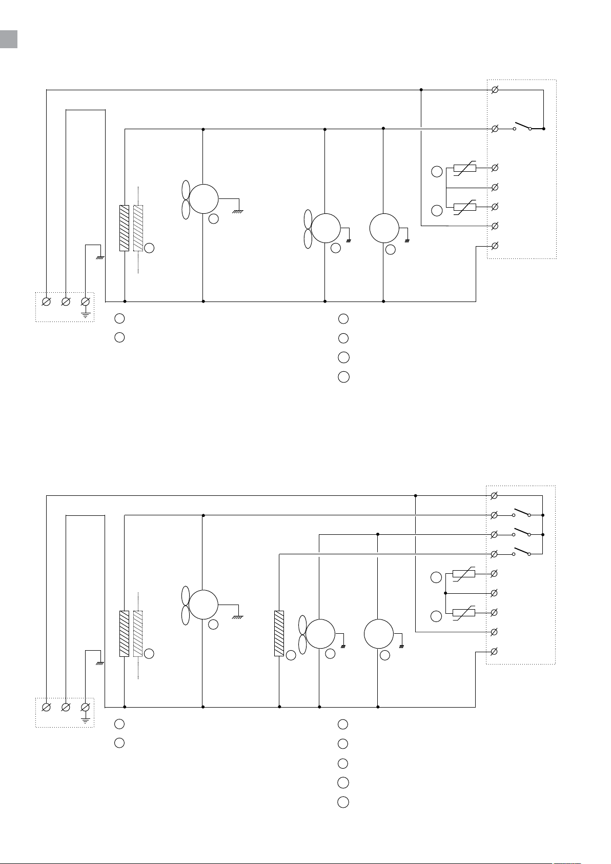
COOLERS
XW20LRH
1
2
NL
2
Door frame heater (Replacement in cabinet)
5
Evaporator fan
FREEZERS
M
11
5
10
MM
72
7
Condenser fan
8
Compressor
10
Evaporator probe
11
Cabinet probe
8
11
12
10
9
8
XW60LRH
2/5
4
1
6
10
M
5
11
MM
9
NL
2
Door frame heater (Replacement in cabinet)
5
Evaporator fan
72
7
8
9
8
Condenser fan
Compressor
Defrost heater
10
12
11
9
8
10
Evaporator probe
11
Cabinet probe
73
Page 74
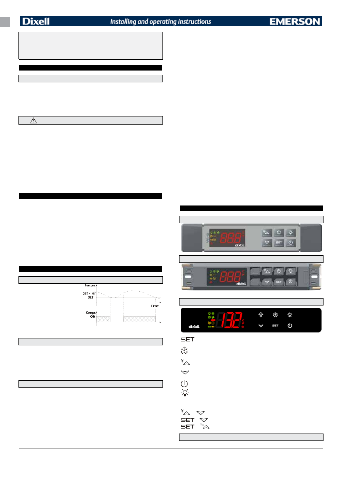
Digital controller with off cycle defrost and auxiliary
The regulation is performed according to
relay
XW20LR –XW20LRH
1. GENERAL WARNING
1.1 PLEASE READ BEFORE USING THIS MANUAL
• This manual is part of the product and should be kept near the instrument for easy and quick
reference.
• The instrument shall not be used for purposes different from those described hereunder. It cannot be
used as a safety device.
• Check the application limits before proceeding.
• Dixell Srl reserves the right to change the composition of its products, even without notice, ensuring
the same and unchanged functionality.
1.2
• Check the supply voltage is correct before connecting the instrument.
• Do not expose to water or moisture: use the controller only within the operating limits avoiding sudden
• Warning: disconnect all electrical connections before any kind of maintenance.
• Fit the probe where it is not accessible by the End User. The instrument must not be opened.
• In case of failure or faulty operation send the instrument back to the distributor or to “Dixell S.r.l.” (see
• Consider the maximum current which can be applied to each relay (see Technical Data).
• Ensure that the wires for probes, loads and the power supply are separated and far enough from each
• In case of applications in industrial environments, the use of mains filters (our mod. FT1) in parallel
• Dixell Srl reserves the right to change the composition of its products, even without notice, ensuring
2. GENERAL DESCRIPTION
Model XW20LR, XW20LRH, format 38x185mm, is a digital thermostat with off cycle defrost designed
for refrigeration applications at medium and low temperature. It has 2 relay outputs, one to control
compressor and the other (configurable) to control light, auxiliary or alarm. It could be provided with a
Real Time Clock which allows programming of up to 6 daily defrost cycles, divided into holidays and
workdays. A “Day and Night” function with two different set points is fitted for energy saving. It is also
provided with up to three NTC or PTC probe inputs, the first one for temperature control, the second
one, to be located onto the evaporator and to control the defrost termination temperature. The third
probe is used to signal the condenser temperature alarm or to display a temperature. One of the 2
digital inputs can operate as fourth probe input.
The HOT KEY output allows to connect the unit, by means of the external module XJ485-CX, to a
network line ModBUS-RTU compatible such as the dIXEL monitoring units of X-WEB family. It
allows to program the controller by means the HOT KEY programming keyboard.
The instrument is fully configurable through special parameters that can be easily programmed
through the keyboard.
3. CONTROLLING LOADS
SAFETY PRECAUTIONS
temperature changes with high atmospheric humidity to prevent formation of condensation
address) with a detailed description of the fault.
other, without crossing or intertwining.
with inductive loads could be useful.
the same and unchanged functionality.
b. Auxiliary thermostat (es. anti-sweat heaters)
Parameters involved:
- ACH Type of regulation: heating/cooling;
- SAA Set point auxiliary relay
- SHy Differential for auxiliary relay
- ArP Probe for auxiliary relay
- Sdd Auxiliary output off during defrost
By means of these 5 parameters the functioning of the auxiliary relay can be set.
NOTE: Set oA1 =AUS and ArP= nP (no probe for auxiliary output).
In this case the relay 5-6/7 can be activated only by digital input with i1F or i2F = AUS.
3.3.3 On/off relay – oA1 = onF
In this case the relay is activated when the controller is turned on and de-activated when the controller
is in stand-by mode.
3.3.4 Neutral zone regulation
With oA1 = db the relay 5-6/7 can control a heater element to perform a neutral zone action.
oA1 cut in = SET-HY
oA1 cut out = SET
3.3.5 Second compressor
With oA1 = CP2, the relay 5-6/7 operates as second compressor: it is activated in parallel with the
relay of the first compressor, with a possible delay set in the AC1 parameter. Both the relays are
switched off at the same time.
3.3.6 Alarm relay
With oA1 = ALr the relay 5-6/7 operates as alarm relay. It is activated every time an alarm happens.
Its status depends on the tbA parameter:
With “tbA = y”, the relay is silenced by pressing any key.
With “tbA = n”, the alarm relay remains on until the alarm condition recovers.
3.3.7 Night blind management during energy saving cycles
With oA1 = HES, the relay 5-6/7 operates to manage the night blind: the relay is energised when the
energy saving cycle is activated, by digital input, frontal button or RTC (optional).
4. FRONT PANEL COMMANDS
4.1 XW20LR:STANDARD FRONTAL PANEL
4.2 XW20LR: STEEL FINISHING
3.1 COMPRESSOR
the temperature measured by the
thermostat probe with a positive
differential from the set point: if the
temperature increases and reaches set
point plus differential the compressor is
started and then turned off when the
temperature reaches the set point value
again.
In case of fault in the thermostat probe the start and stop of the compressor are timed through
parameters “COn” and “COF”.
3.2 DEFROST
Defrost is performed through a simple stop of the compressor. The defrost interval depends on the
presence of the RTC (optional). If the RTC is present is controlled by means of parameter “EdF”:
- with EdF=in the defrost is made every “IdF” time – standard way for controller without RTC.
- with EdF = “rtc”, the defrost is made in real time depending on the hours set in the parameters
Ld1..Ld6 on workdays and in Sd1…Sd6 in holidays;
Other parameters are used to control defrost cycles: its maximum length (MdF) and two defrost
modes: timed or controlled by the evaporator’s probe (P2P).
3.3 AUXILIARY RELAY CONFIGURATION - TERM.5-6/7, PAR. OA1
The functioning of the auxiliary relay (terminals. 5-6/7) can be set by the oA1 parameter, according to
the kind of application. In the following paragraph the possible setting:
3.3.1 Light relay - oA1= Lig
With oA1 = Lig, the 5-6/7 relay is set as light. It is activated by key or when i1F = dor.
3.3.2 Alarm relay - oA1= AUS
There are 2 possibilities:
a. Activation via digital input (oA1 = AUS, i1F or i2F = AUS)
With oA1 = AUS and i2F or i1F = AUS the relay 5-6/7 is activated via digital input and remains ON
until the digital input is activated or is silenced by pressing any key.
1592027520 XW20LR XW20LRH RTC GB r2.0 18.03.2015 XW20LR – XW20LRH 1/5
4.1 XW20LRH
: To display target set point; in programming mode it selects a parameter or confirm an
operation.
(DEF) To start a manual defrost.
(UP): To see the max. stored temperature; in programming mode it browses the parameter
codes or increases the displayed value.
(DOWN) To see the min stored temperature; in programming mode it browses the parameter
codes or decreases the displayed value.
To switch the instrument off, if onF = oFF.
To switch the light, if oA1 = Lig.
KEY COMBINATIONS:
+
To lock & unlock the keyboard.
+ To enter in programming mode.
+
4.2 USE OF LEDS
Each LED function is described in the following table.
To return to the room temperature display.
74
Page 75
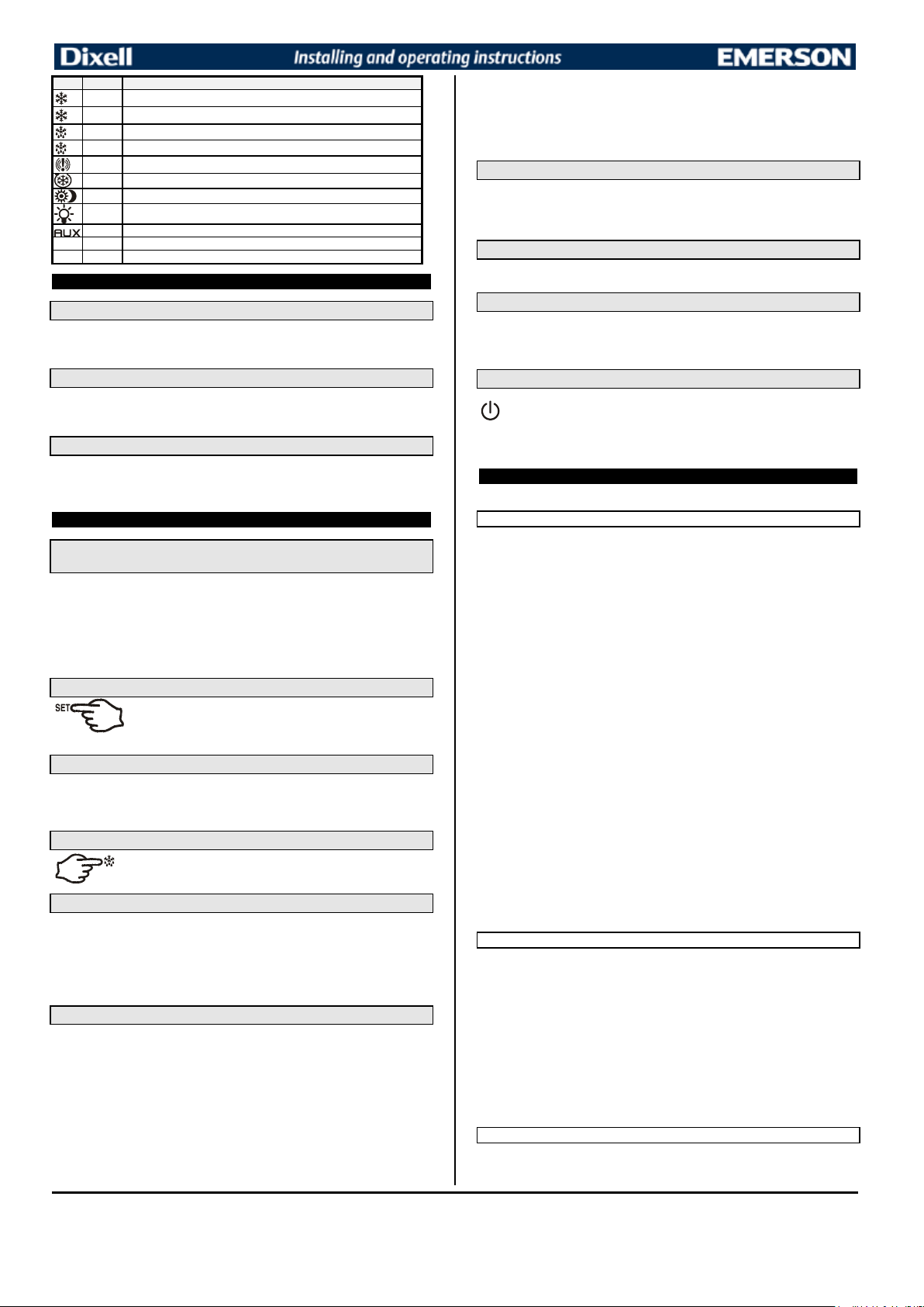
LED
MODE
FUNCTION
ON
Compressor enabled
Flashing
Anti-short cycle delay enabled
ON
Defrost enabled
Flashing
Drip time in progress
ON
An alarm is occurring
ON
Continuous cycle is running
ON
Energy saving enabled
ON
Light on
ON
Auxiliary relay on
°C
ON
Measurement unit
°C
Flashing
Programming phase
1. Push and immediately release the SET key: the display will show the Set
2. Push and immediately release the SET key or wait for 5 seconds to
Push the DEF key for more than 2 seconds and a manual defrost will start.
NOTE2: the set value is stored even when the procedure is exited by waiting the time-out to expire.
With “onF = oFF”, pushing the ON/OFF key, the instrument is switched off. The “OFF”
6.6.2 HOW TO MOVE A PARAMETER FROM THE HIDDEN MENU TO THE
FIRST LEVEL AND VICEVERSA.
Each parameter present in the HIDDEN MENU can be removed or put into “THE FIRST LEVEL” (user
level) by pressing “SET + n
In HIDDEN MENU when a parameter is present in First Level the decimal point is on.
”.
6.7 HOW TO LOCK THE KEYBOARD
1. Keep pressed for more than 3 s the UP + DOWN keys.
2. The “POF” message will be displayed and the keyboard will be locked. At this point it will be
possible only to see the set point or the MAX o Min temperature stored
3. If a key is pressed more than 3s the “POF” message will be displayed.
6.8 TO UNLOCK THE KEYBOARD
Keep pressed together for more than 3s the o and n
5. MAX & MIN TEMPERATURE MEMORIZATION
5.1 HOW TO SEE THE MIN TEMPERATURE
1. Press and release the n
key.
2. The “Lo” message will be displayed followed by the minimum temperature recorded.
3. By pressing the n
key again or by waiting 5s the normal display will be restored.
5.2 HOW TO SEE THE MAX TEMPERATURE
1. Press and release the o
key.
2. The “Hi” message will be displayed followed by the maximum temperature recorded.
3. By pressing the o
key again or by waiting 5s the normal display will be restored.
5.3 HOW TO RESET THE MAX AND MIN TEMPERATURE RECORDED
1. Hold press the SET key for more than 3s, while the max. or min temperature is displayed. (rSt
message will be displayed)
2. To confirm the operation the “rSt” message starts blinking and the normal temperature will be
displayed.
6. MAIN FUNCTIONS
6.1 TO SET THE CURRENT TIME AND DAY (ONLY FOR INSTRUMENTS
WITH RTC)
When the instrument is switched on, it’s necessary to program the time and day.
1. Enter the Pr1 programming menu, by pushing the SET + n
2. The rtc parameter is displayed. Push the SET key to enter the real time clock menu.
3. The Hur (hour) parameter is displayed.
4. Push the SET and set current hour by the UP and Down keys, then push SET to confirm
the value..
5. Repeat the same operations on the Min (minutes) and dAy (day) parameters.
To exit: Push SET+UP keys or wait for 15 sec without pushing any keys.
keys for 3s.
6.2 HOW TO SEE THE SET POINT
point value;
display the probe value again.
6.3 HOW TO CHANGE THE SET POINT
1. Push the SET key for more than 2 seconds to change the Set point value;
2. The value of the set point will be displayed and the “°C” LED starts blinking;
3. To change the Set value push the o
4. To memorise the new set point value push the SET key again or wait 10s.
or n
arrows within 10s.
6.4 HOW TO START A MANUAL DEFROST
6.5 HOW TO CHANGE A PARAMETER VALUE
To change the parameter’s value operate as follows:
1. Enter the Programming mode by pressing the Set + n
2. Select the required parameter. Press the “SET” key to display its value
3. Use “UP” or “DOWN” to change its value.
4. Press “SET” to store the new value and move to the following parameter.
To exit: Press SET + UP or wait 15s without pressing a key.
NOTE: the set value is stored even when the procedure is exited by waiting the time-out to expire.
keys for 3s (the “°C” LED starts blinking).
6.6 THE HIDDEN MENU
The hidden menu Includes all the parameters of the instrument.
6.6.1 HOW TO ENTER THE HIDDEN MENU
1. Enter the Programming mode by pressing the Set + n
2. Released the keys, then push again the Set+n
displayed immediately followed from the HY parameter.
NOW YOU ARE IN THE HIDDEN MENU.
3. Select the required parameter.
4. Press the “SET” key to display its value
or n
5. Use o
6. Press “SET” to store the new value and move to the following parameter.
To exit: Press SET + o
NOTE1: if none parameter is present in Pr1, after 3s the “noP” message is displayed. Keep the keys
pushed till the Pr2 message is displayed.
to change its value.
or wait 15s without pressing a key.
keys for 3s (the “°C” LED starts blinking).
keys for more than 7s. The Pr2 label will be
displayed.
6.9 THE CONTINUOUS CYCLE
When defrost is not in progress, it can be activated by holding the “o
seconds. The compressor operates to maintain the “ccS” set point for the time set through the “CCt”
parameter. The cycle can be terminated before the end of the set time using the same activation key
“
” for 3 seconds.
o
6.10 THE ON/OFF FUNCTION
message is displayed. In this configuration, the regulation is disabled.
To switch the instrument on, push again the ON/OFF key.
WARNING: Loads connected to the normally closed contacts of the relays are always supplied
and under voltage, even if the instrument is in stand by mode.
7. PARAMETERS
rtc Real time clock menu (only for controller with RTC): to set the time and date and defrost start
time.
REGULATION
Hy Differential: (0,1 ÷ 25,5°C / 1÷255 °F) Intervention differential for set point. Compressor Cut IN is
Set Point + differential (Hy). Compressor Cut OUT is when the temperature reaches the set
point.
LS Minimum set point: (- 50°C÷SET/-58°F÷SET): Sets the minimum value for the set point.
US Maximum set point: (SET÷110°C/ SET÷230°F). Set the maximum value for set point.
Ot Thermostat probe calibration: (-12.0÷12.0°C; -120÷120°F) allows to adjust possible offset of
the thermostat probe.
P2P Evaporator probe presence: n= not present: the defrost stops by time; y= present: the defrost
stops by temperature.
OE Evaporator probe calibration: (-12.0÷12.0°C; -120÷120°F). allows to adjust possible offset of
the evaporator probe.
P3P Third probe presence (P3): n= not present:, the terminals 13-14 operate as digital input.; y=
present:, the terminals 13-14 operate as third probe.
O3 Third probe calibration (P3): (-12.0÷12.0°C; -120÷120°F). allows to adjust possible offset of the
third probe.
OdS Outputs activation delay at start up: (0÷255min) This function is enabled at the initial start up
of the instrument and inhibits any output activation for the period of time set in the parameter.
AC Anti-short cycle delay: (0÷50 min) minimum interval between the compressor stop and the
following restart.
nd
AC1 2
compressor delay at start up (0÷255s) Used only if oA3 = cP2 Time interval between the
switching on of the first compressor and the second one.
rtr Percentage of the second and first pr obe for regulation (0÷100; 100 = P1, 0 = P2 ): it allows
to set the regulation according to the percentage of the first and second probe, as for the
following formula (rtr(P1-P2)/100 + P2).
CCt Compressor ON time during continuous cycle: (0.0÷24.0h; res. 10min) Allows to set the
length of the continuous cycle: compressor stays on without interruption for the CCt time. Can be
used, for instance, when the room is filled with new products.
CCS Set point for continuous cycle: (-50÷150°C) it sets the set point used during the continuous
cycle.
COn Compressor ON time with faulty probe: (0÷255 min) time during which the compressor is
active in case of faulty thermostat probe. With COn=0 compressor is always OFF.
COF Compressor OFF time with faulty probe: (0÷255 min) time during which the compressor is
OFF in case of faulty thermostat probe. With COF=0 compressor is always active.
CH Type of action: CL = cooling; Ht = heating.
DISPLAY
CF Temperature measurement unit: °C=Celsius; °F=Fahrenheit. WARNING: When the
measurement unit is changed the SET point and the values of the parameters Hy, LS, US, Ot,
ALU and ALL have to be checked and modified if necessary).
rES Resolution (for °C): (in = 1°C; dE = 0.1 °C) allows decimal point display.
Lod Instrument display: (P1; P2, P3, P4, SET, dtr): it selects which probe is displayed by the
instrument: P1 = Thermostat probe; P2 = Evaporator probe; P3 = Third probe(only for model with
this option enabled); P4 = Fourth probe, SET = set point; dtr = percentage of visualization.
rEd X- REP display (optional): (P1; P2, P3, P4, SET, dtr): it selects which probe is displayed by X-
REP: P1 = Thermostat probe; P2 = Evaporator probe; P3 = Third probe(only for model with this
option enabled); P4 = Fourth probe, SET = set point; dtr = percentage of visualization.
dLy Display delay: (0 ÷20.0m; resul. 10s) when the temperature increases, the display is updated of
1 °C/1°F after this time.
dtr Percentage of the second and first probe for visualization when Lod = dtr (0÷100; 100 =
P1, 0 = P2 ): if Lod = dtr it allows to set the visualization according to the percentage of the first
and second probe, as for the following formula (dtr(P1-P2)/100 + P2).
DEFROST
EdF Defrost mode (only for controller with RTC):
rtc = Real Time Clock mode. Defrost time follows Ld1÷Ld6 parameters on workdays and
Sd1÷Sd6 on holidays.
1592027520 XW20LR XW20LRH RTC GB r2.0 18.03.2015 XW20LR – XW20LRH 2/5
keys, till the “Pon” message will be
” key pressed for about 3
7575
Page 76
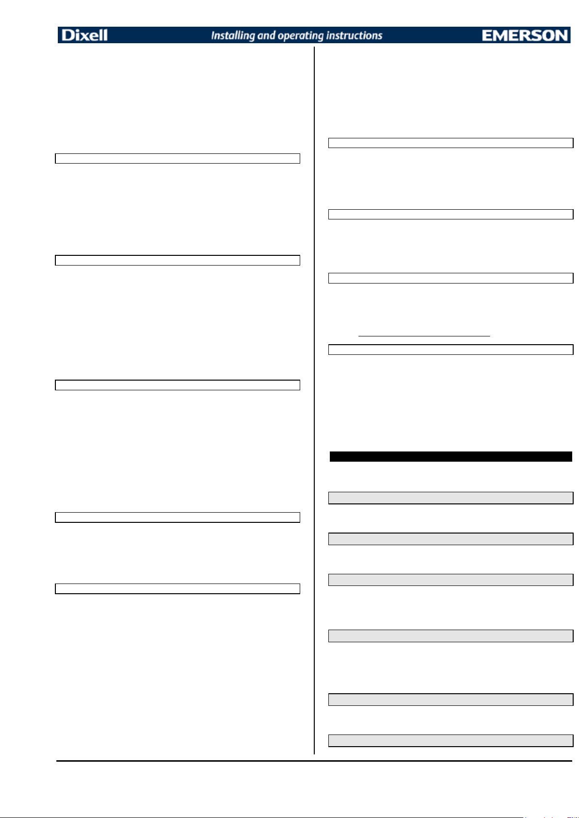
in = interval mode. The defrost starts when the time “Idf” is expired.
dFP Probe selection for defrost termination: nP = no probe; P1 =thermostat probe; P2 =
evaporator probe; P3 =configurable probe; P4 = fourth probe.
dtE Defrost termination temperature: (-50÷50 °C/ -58÷122°F) (Enabled only when EdF=Pb) sets
the temperature measured by the evaporator probe, which causes the end of defrost.
IdF Interval between defrost cycles: (0÷120h) Determines the time interval between the beginning
of two defrost cycles.
MdF (Maximum) length for defrost: (0÷255min) When P2P = n, (not evaporator probe: timed
defrost) it sets the defrost duration, when P2P = y (defrost end based on temperature) it sets the
maximum length for defrost.
dFd Temperature displayed during defrost: (rt = real temperature; it = temperature at defrost start;
SEt = set point; dEF = “dEF” label)
dAd MAX display delay after defrost: (0÷120min). Sets the maximum time between the end of
defrost and the restarting of the real room temperature display.
AUXILIARY THERMOSTAT CONFIGURATION (terms. 5-67/) – OA1 = AUS
ACH Kind of regulation for auxiliary relay: Ht = heating; CL = cooling
SAA Set Point for auxiliary relay: (-50,0÷110,0°C; -58÷230°F) it defines the room temperature set
point to switch auxiliary relay.
SHy Differential for auxiliary output: (0,1 ÷ 25,5°C / 1÷255 °F) Intervention differential for auxiliary
output set point.
With ACH = cL AUX Cut in is SAA + SHy; . AUX Cut out is SAA
With ACH = Ht AUX Cut in is SAA - SHy; . AUX Cut out is SAA
ArP Probe selection for auxiliary: nP = no probe, the auxiliary relay is switched only by button; P1
= Probe 1 (Thermostat probe); P2 = Probe 2 (evaporator probe); P3 = Probe 3 (display probe);
P4 = Probe 4 fourth probe.
Sdd Auxiliary relay off during defrost: n = the auxiliary relay 5-6/7 operates during defrost.
y = the auxiliary relay 5-6/7 is switched off during defrost.
ALARMS
ALP Probe selection for alarm: P1 = Probe 1; P2 = Probe 2; P3 = Probe 3; P4 = Fourth probe.
ALC Temperature alarms configuration: (Ab; rE) Ab= absolute temperature: alarm temperature is
given by the ALL or ALU values. rE = temperature alarms are referred to the set point.
Temperature alarm is enabled when the temperature exceeds the “SET+ALU” or “SET-ALL”
values.
ALU MAXIMUM temperature alarm: (SET÷110°C; SET÷230°F) when this temperature is reached
the alarm is enabled, after the “ALd” delay time.
ALL Minimum temperature alarm: (-50.0 ÷ SET °C; -58÷230°F when this temperature is reached
the alarm is enabled, after the “ALd” delay time.
AFH Differential for temperature alarm recovery: (0,1÷25,5°C; 1÷45°F) Intervention differential for
recovery of temperature alarm.
ALd Temperature alarm delay: (0÷255 min) time interval between the detection of an alarm
condition and alarm signalling.
dAO Exclusion of temperature alarm at start-up: (from 0.0 min to 23.5h) time interval between the
detection of the temperature alarm condition after instrument power on and alarm signalling.
CONDENSER TEMPERATURE ALARM
AP2 Probe selection for temperature alarm of condenser: nP = no probe; P1 =thermostat probe;
P2 = defrost termination probe; P3 =configurable probe; P4 = fourth probe.
AL2 Low temperature alarm of condenser: (-55÷150°C) when this temperature is reached the LA2
alarm is signalled, possibly after the Ad2 delay.
Au2 High temperature alarm of condenser: (-55÷150°C) when this temperature is reached the HA2
alarm is signalled, possibly after the Ad2 delay.
AH2 Differential for temperature condenser alarm recovery: (0,1÷25,5°C; 1÷45°F)
Ad2 Condenser temperature alarm delay: (0÷255 min) time interval between the detection of the
condenser alarm condition and alarm signalling.
dA2 Condenser temperature alarm exclusion at start up: (from 0.0 min to 23.5h, res. 10min)
bLL Compressor off with low temperature alarm of condenser: n = no: compressor keeps on
working; Y = yes, compressor is switched off till the alarm is present, in any case regulation
restarts after AC time at minimum.
AC2 Compressor off with high temperature alarm of condenser: n = no: compressor keeps on
working; Y = yes, compressor is switched off till the alarm is present, in any case regulation
restarts after AC time at minimum.
AUXILIARY RELAY
tbA Alarm relay silencing (with oA1 =ALr):
n= silencing disabled: alarm relay stays on till alarm condition lasts,
y =silencing enabled: alarm relay is switched OFF by pressing a key during an alarm
oA1 Second relay configuration (5-6/7): dEF, FAn: do not select it!. ALr: alarm; Lig: light; AuS:
Auxiliary relay; onF: always on with instrument on; db= neutral zone; cP2 = second compressor;
dF2: do not select it!;. HES:. night blind
AoP Alarm relay polarity: it set if the alarm relay is open or closed when an alarm happens. CL=
terminals 1-4 closed during an alarm; oP = terminals 1-4 open during an alarm
DIGITAL INPUTS
i1P Digital input polarity (13-14): oP: the digital input is activated by opening the contact; CL: the
digital input is activated by closing the contact.
i1F Digital input configuration (13-14): EAL= external alarm: “EA” message is displayed; bAL=
serious alarm “CA” message is displayed. PAL= pressure switch alarm, “CA” message is
displayed; dor= door switch function; dEF= activation of a defrost cycle; AUS= auxiliary relay for
oA1 or oA4=AUS; Htr= kind of action inversion (cooling – heating); FAn= not set it; ES= Energy
saving; HdF = Holiday defrost (enable only with RTC); onF = to switch the controller off.
did (0÷255 min) with i1F= EAL or i1F = bAL digital input alarm delay (13-14): delay between the
detection of the external alarm condition and its signalling.
with i1F= dor: door open signalling delay
with i1F= PAL: time for pressure switch function: time interval to calculate the number of the
pressure switch activation.
nd
i2P 2
digital input polarity (13-19): oP: the digital input is activated by opening the contact; CL:
the digital input is activated by closing the contact.
nd
i2F 2
digital input configuration (13-19): EAL= external alarm: “EA” message is displayed; bAL=
serious alarm “CA” message is displayed. PAL= pressure switch alarm, “CA” message is
displayed; dor= door switch function; dEF= activation of a defrost cycle; AUS=not enabled; Htr=
kind of action inversion (cooling – heating); FAn= not set it; ES= Energy saving; HdF = Holiday
defrost (enable only with RTC); onF = to switch the controller off.
d2d (0÷255 min) with i2F= EAL or i2F= bAL 2
the detection of the external alarm condition and its signalling.
nd
digital input alarm delay (13-19): delay between
with i2F= dor: door open signalling delay
with i2F= PAL: time for pressure switch function: time interval to calculate the number of the
pressure switch activation.
nPS Pressure switch number: (0
interval, before signalling the alarm event (I2F= PAL).
If the nPS activation in the did time is reached, switch off and on the instrument to restart
normal regulation.
odc Compressor status when open door: no, Fan = normal; CPr, F_C = Compressor OFF.
rrd Outputs restart after doA alarm: no= outputs not affected by the doA alarm; yES = outputs
restart with the doA alarm.
HES Temperature increase during the Energy Saving cycle: (-30,0°C
increasing value of the set point during the Energy Saving cycle.
TO SET CURRENT TIME AND WEEKLY HOLIDAYS (ONLY FOR MODELS WITH RTC)
Hur Current hour (0 ÷ 23 h)
Min Current minute (0 ÷ 59min)
dAY Current day (Sun ÷ SAt)
Hd1 First weekly holiday (Sun ÷ nu) Set the first day of the week which follows the holiday times.
Hd2 Second weekly holiday (Sun ÷ nu) Set the second day of the week which follows the holiday
times.
N.B. Hd1,Hd2 can be set also as “nu” value (Not Used).
TO SET ENERGY SAVING TIMES (ONLY FOR MODELS WITH RTC)
ILE Energy Saving cycle start during workdays: (0 ÷ 23h 50 min.) During the Energy Saving
cycle the set point is increased by the value in HES so that the operation set point is SET +
HES.
dLE Energy Saving cycle length during workdays: (0 ÷ 24h 00 min.) Sets the duration of the
Energy Saving cycle on workdays.
ISE Energy Saving cycle start on holidays. (0 ÷ 23h 50 min.)
dSE Energy Saving cycle length on holidays (0 ÷ 24h 00 min.)
TO SET DEFROST TIMES (ONLY FOR MODELS WITH RTC)
Ld1÷Ld6 Workday defrost start (0 ÷ 23h 50 min.) These parameters set the beginning of the 6
programmable defrost cycles during workdays. Ex. When Ld2 = 12.4 the second defrost starts at
12.40 during workdays.
Sd1÷Sd6 Holiday defrost start (0 ÷ 23h 50 min.) These parameters set the beginning of the 6
programmable defrost cycles on holidays. Ex. When Sd2 = 3.4 the second defrost starts at 3.40
on holidays.
N.B. :To disable a defrost cycle set it to “nu”(not used). Ex. If Ld6=nu ; the sixth defrost
cycle is disabled
OTHER
Adr Serial address (1÷244): Identifies the instrument address when connected to a ModBUS
compatible monitoring system.
PbC Type of probe: it allows to set the kind of probe used by the instrument: PTC = PTC probe, ntc =
NTC probe.
onF on/off key enabling: nu = disabled; oFF = enabled; ES = not set it.
dP1 Thermostat probe display
dP2 Evaporator probe display
dP3 Third probe display- optional.
rSE Real set point: it shows the set point used during the energy saving cycle or during the
continuous cycle.
rEL Software release for internal use.
Ptb Parameter table code: readable only.
÷15) Number of activation of the pressure switch, during the “did”
÷30,0°C) it sets the
8. DIGITAL INPUTS
The first digital input is enabled with P3P = n.
With P3P = n and i1F = i2F the second digital input is disabled
The free voltage digital inputs are programmable by the “i1F” and i2F parameters.
8.1 GENERIC ALARM (i1F or i2F = EAL)
As soon as the digital input is activated the unit will wait for “did” time delay before signalling the
“EAL” alarm message. The outputs status don’t change. The alarm stops just after the digital input is
de-activated.
8.2 SERIOUS ALARM MODE (i1F or i2F = bAL)
When the digital input is activated, the unit will wait for “did” delay before signalling the “CA” alarm
message. The relay outputs are switched OFF. The alarm will stop as soon as the digital input is deactivated.
8.3 PRESSURE SWITCH (i1F or i2F = PAL)
If during the interval time set by “did” parameter, the pressure switch has reached the number of
activation of the “nPS” parameter, the “CA” pressure alarm message will be displayed. The
compressor and the regulation are stopped. When the digital input is ON the compressor is always
OFF. If the nPS activation in the did time is reached, switch off and on the instrument to restart
normal regulation.
8.4 DOOR SWITCH INPUT (i1F or i2F = dor)
It signals the door status and the corresponding relay output status through the “odc” parameter: no,
Fan = normal (any change); CPr, F_C = Compressor OFF.
Since the door is opened, after the delay time set through parameter “did”, the door alarm is enabled,
the display shows the message “dA” and the regulation restarts is rtr = yES. The alarm stops as
soon as the external digital input is disabled again. With the door open, the high and low temperature
alarms are disabled.
8.5 START DEFROST (i1F or i2F = dEF)
It starts a defrost if there are the right conditions. After the defrost is finished, the normal regulation will
restart only if the digital input is disabled otherwise the instrument will wait until the “MdF” safety time
is expired.
8.6 SWITCH THE AUXILIARY RELAY (i1F or i2F = AUS)
With oA1 = AUS the digital input switched the status of the auxiliary relay
1592027520 XW20LR XW20LRH RTC GB r2.0 18.03.2015 XW20LR – XW20LRH 3/5
76
Page 77
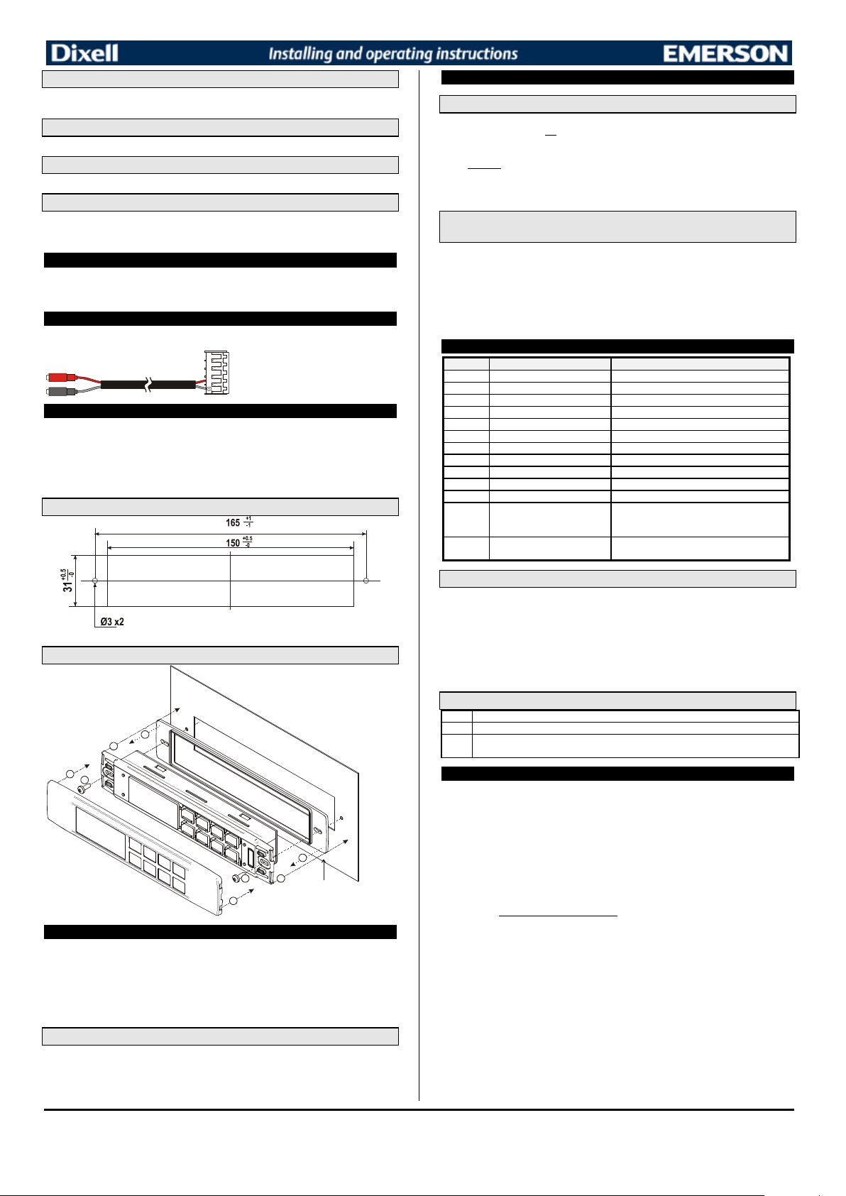
8.7 ENERGY SAVING (i1F or i2F = ES)
To connect the X-REP to the instrument the
Message
Cause
Outputs
“P1”
Room probe failure
Compressor output acc. to par. “Con” and “COF”
“P2”
Second probe failure
Defrost end is timed
“P3”
Third probe failure
Outputs unchanged
“HA”
Maximum temperature alarm
Outputs unchanged.
“LA”
Minimum temperature alarm
Outputs unchanged.
"HA2"
Condenser high temperature
It depends on the “Ac2” parameter
"LA2"
Condenser low temperature
It depends on the “bLL” parameter
“dA”
Door open
Loads according to the “odC” parameter
“EA”
External alarm
Output unchanged.
“CA”
Serious external alarm (i1F=bAL)
All outputs OFF.
“CA”
Pressure switch alarm (i1F=PAL)
All outputs OFF
“rtc”
Real time clock alarm
Alarm output ON; Other outputs unchanged;
has to be set
rtF
Real time clock board failure
Alarm output ON; Other outputs unchanged;
Defrosts according to par. “IdF” Contact the service
Pon
Keyboard unlocked.
PoF
Keyboard locked
noP
In programming mode: none parameter is present in Pr1
On the display or in dP2, dP3, dP4: the selected probe is nor enabled
The Energy Saving function allows to change the set point value as the result of the SET+ HES
(parameter) sum. This function is enabled until the digital input is activated.
8.8 HOLIDAY DEFROST (i1F or i2F = HDF) –ONLY FOR MODELS WITH RTC
This function enabled the holiday defrost setting.
8.9 ON OFF FUNCTION (i1F or i2F = onF)
To switch the controller on and off.
8.10 DIGITAL INPUTS POLARITY
The digital input polarity depends on the “i1P” and “i2P” parameters.
i1P or i2P =CL: the input is activated by closing the contact.
i1P or i2P=OP: the input is activated by opening the contact
9. TTL SERIAL LINE – FOR MONITORING SYSTEMS
The TTL serial line, available through the HOT KEY connector, allows by means of the external
TTL/RS485 converter, XJ485-CX, to connect the instrument to a monitoring system ModBUS-RTU
compatible such as the X-WEB500/3000/300.
10. X-REP OUTPUT – OPTIONAL
As optional, an X-REP can be connected to the instrument, trough the HOY KEY connector. The XREP output EXCLUDES the serial connection.
following connectors must be used CAB51F(1m), CAB-52F(2m), CAB-55F(5m),
11. INSTALLATION AND MOUNTING
The controller shall be mounted on vertical panel, in a 150x31 mm hole, and fixed using two screws ∅
3 x 2mm (only for XW20LR).
XW20LR: to obtain an IP65 protection grade use the front panel rubber gasket (mod. RG-L). The
temperature range allowed for correct operation is 0 - 60 °C. Avoid places subject to strong vibrations,
corrosive gases, excessive dirt or humidity. The same recommendations apply to probes. Let the air
circulate by the cooling holes.
13. HOW TO USE THE HOT KEY
13.1 HOW TO PROGRAM A HOT KEY FROM THE INSTRUMENT (UPLOAD)
1. Program one controller with the front keypad.
2. When the controller is ON, insert the “Hot key” and push o
followed a by flashing “End”
3. Push “SET” key and the End will stop flashing.
4. Turn OFF the instrument remove the “Hot Key”, then turn it ON again.
NOTE: the “Err” message is displayed for failed programming. In this case push again o
want to restart the upload again or remove the “Hot key” to abort the operation.
key; the "uPL" message appears
key if you
13.2 HOW TO PROGRAM AN INSTRUMENT USING A HOT KEY
(DOWNLOAD)
1. Turn OFF the instrument.
2. Insert a programmed “Hot Key” into the 5 PIN receptacle and then turn the Controller ON.
3. Automatically the parameter list of the “Hot Key” is downloaded into the Controller memory,
the “doL” message is blinking followed a by flashing “End”.
4. After 10 seconds the instrument will restart working with the new parameters.
5. Remove the “Hot Key”..
NOTE the message “Err” is displayed for failed programming. In this case turn the unit off and then on
if you want to restart the download again or remove the “Hot key” to abort the operation.
14. ALARM SIGNALS
11.1 CUT OUT
Defrosts according to par. “IdF” Set real time clock
14.1 ALARM RECOVERY
Probe alarms P1”, “P2” and “P4” start some seconds after the fault in the related probe; they
automatically stop some seconds after the probe restarts normal operation. Check connections before
replacing the probe.
XW20LRH: the holes are not required
11.2 STEEL FINISHING MOUNTING
Temperature alarms “HA”, “LA” “HA2” and “LA2” automatically stop as soon as the temperature
returns to normal values.
Alarms “EA” and “CA” (with i1F=bAL) recover as soon as the digital input is disabled.
Alarm “CA” (with i1F=PAL) recovers only by switching off and on the instrument.
Real time clock alarm rtC, it stops as soon as the correct hour and day are set.
Real time clock alarm rtF, the clock board has to be replaced. Contact the service.
14.2 OTHER MESSAGES
1
2
4
3
1
23
RG-LX gascke
4
(optional)
12. ELECTRICAL CONNECTIONS
The instruments are provided with screw terminal block to connect cables with a cross section up to
2
2,5 mm
for the digital and analogue inputs. Relays and power supply have a Faston connection
(6,3mm). Heat-resistant cables have to be used. Before connecting cables make sure the power
supply complies with the instrument’s requirements. Separate the probe cables from the power supply
cables, from the outputs and the power connections. Do not exceed the maximum current allowed on
each relay, in case of heavier loads use a suitable external relay.
N.B. Maximum current allowed for all the loads is 20A.
12.1 PROBE CONNECTION
The probes shall be mounted with the bulb upwards to prevent damages due to casual liquid
infiltration. It is recommended to place the thermostat probe away from air streams to correctly
measure the average room temperature. Place the defrost termination probe among the evaporator
fins in the coldest place, where most ice is formed, far from heaters or from the warmest place during
defrost, to prevent premature defrost termination.
1592027520 XW20LR XW20LRH RTC GB r2.0 18.03.2015 XW20LR – XW20LRH 4/5
15. TECHNICAL DATA
Housing: self extinguishing ABS.
Case: facia 38x185 mm; depth 40mm
Mounting : panel mounting in a 150x31 mm panel cut-out.
Only for XW20LR two screws.
Protection: IP20; Frontal protection: IP65 with frontal gasket mod RG-L or RG-LX.
Connections: Screw terminal block
Power supply: 230Vac or. 110Vac ± 10%, 50/60Hz.
Power absorption: 7VA max.
Display: 3 digits, red LED, 14,2 mm high.
Inputs: Up to 3 NTC or PTC probes.
Digital inputs: free voltage
Relay outputs: Total current on loads MAX. 20A
compressor: relay SPST 20(8) A, 250Vac
light: relay SPST 8A, 250Vac
Other output : buzzer (optional)
Serial output : TTL standard; Communication protocol: Modbus - RTU
Data storing: on the non-volatile memory (EEPROM).
Internal clock back-up: 24 hours (only for model with RTC)
Kind of action: 1B; Pollution grade: normal; Software class: A.;
Over voltage Category: II
Operating temperature: 0÷60 °C; Storage temperature: -30÷85 °C.
Relative humidity: 20÷85% (no condensing)
Measuring and regulation range: NTC probe: -40÷110°C (-40÷230°F);
Resolution: 0,1 °C or 1 °F (selectable); Accuracy (ambient temp. 25°C): ±0,7 °C ±1 digit
PTC probe: -50÷150°C (-58÷302°F)
∅ 3 x 2mm, distance between the holes 165mm
2
≤ 2,5 mm
heat-resistant wiring and 6,3mm Faston
77
Page 78
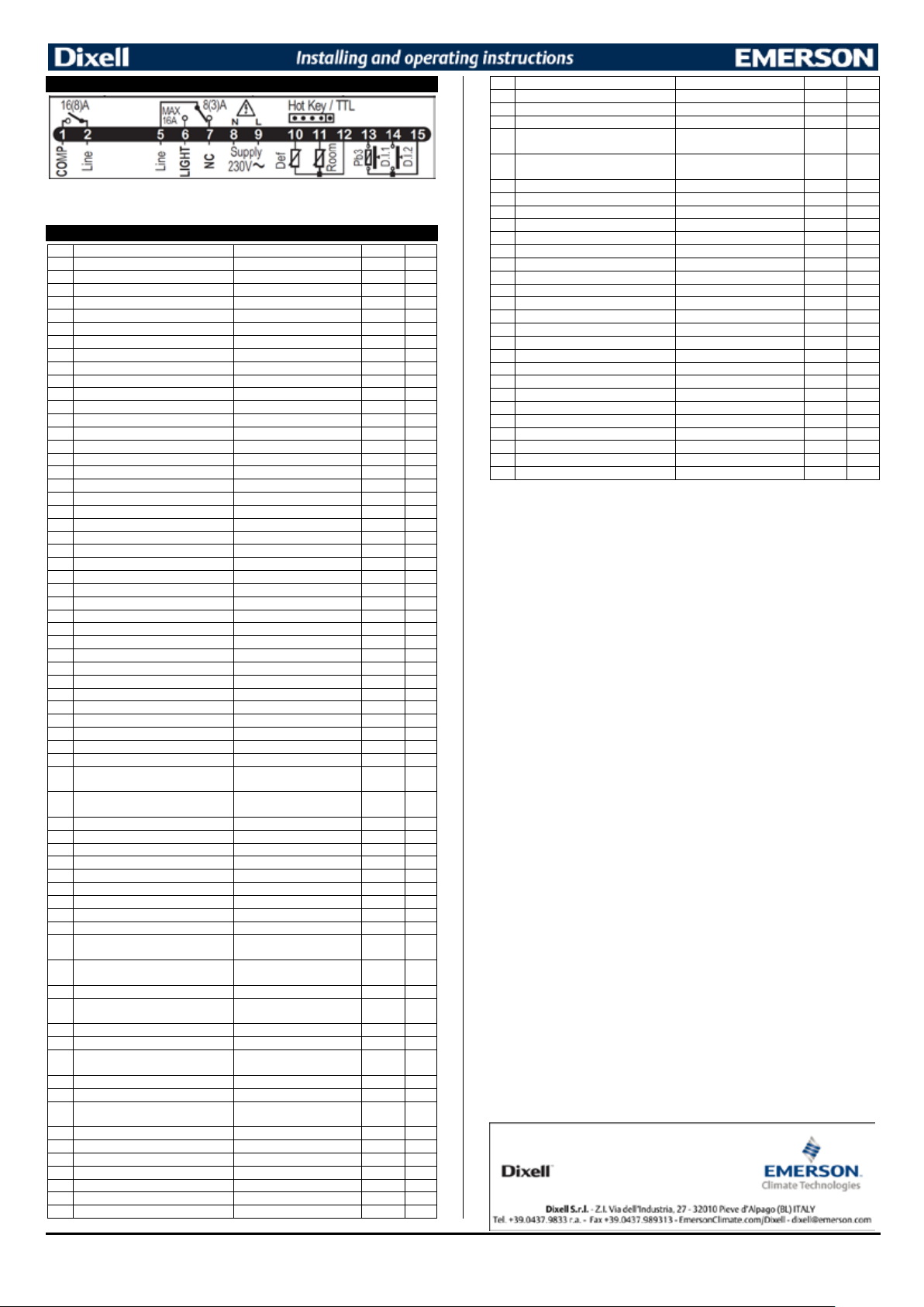
16. CONNECTIONS
Label
Name
Range
Value
Level
Set
Set point
LS - US
3.0
- - -
rtc*
Real time clock menu
-
Pr1
Hy
Differential
(0,1°C ÷ 25,5°C)
Pr1
LS
Minimum set point
(-55,0°C ÷ SET)
-50.0
Pr2
US
Maximum set point
(SET ÷ 150,0°C)
110
Pr2
Ot
P1 probe calibration
(-12,0°C ÷ 12,0°C)
Pr1
P2P
P2 probe presence
n - Y
Pr1
OE
P2 probe calibration
(-12,0°C ÷ 12,0°C)
0.0
Pr2
P3P
P3 probe presence
n - Y
n
Pr2
O3
P3 probe calibration
(-12,0°C ÷ 12,0°C)
0
Pr2
odS
Outputs delay at start up
0 ÷ 255 (min.)
0
Pr2
AC
Anti-short cycle delay
0 ÷ 50 (min.)
1
Pr1
Ac1
Second compressor start delay
0 ÷ 255 (sec.)
5
Pr2
rtr
P1-P2 percentage for regulation
0 ÷ 100 (100=P1 , 0=P2)
100
Pr2
CCt
Continuous cycle duration
0 ÷ 24H0(144)
0.0
Pr2
CCS
Set point for continuous cycle
(-55.0°C ÷ 150,0°C)
3.0
Pr2
COn
Compressor ON time with faulty probe
0 ÷ 255 (min.)
15
Pr2
COF
Compressor OFF time with faulty probe
0 ÷ 255 (min.)
30
Pr2
CH
Kind of action
cL, Ht
cL
Pr1
CF
Temperature measurement unit
°C - °F
°C
Pr2
rES
Resolution
dE – in
dE
Pr1
Lod
Probe displayed
P1 - P2 - P3 - P4 - SEt – dtr
P1
Pr2
rEd2X-REP display
P1 - P2 - P3 - P4 - SEt – dtr
P1
Pr2
dLy
Display temperature delay
0 ÷ 20.0min (ris. 10 sec.)
0.0
Pr2
dtr
P1-P2 percentage for display
1 ÷ 99
50
Pr2
EdF*
Kind of interval for defrost
rtc÷in
in
Pr2
dFP
Probe selection for defrost termination
nP - P1 - P2 – P3 - P4
nP
Pr2
dtE
Defrost termination temperature
(-55.0°C ÷ 50.0°C)
3,0
Pr1
IdF
Interval between defrost cycles
0 ÷ 120 (h)
8
Pr1
MdF
(Maximum) length for defrost
0 ÷ 255 (min.)
Pr1
dFd
Displaying during defrost
rt - it - SEt – dEF
it
Pr2
dAd
MAX display delay after defrost
0 ÷ 255 (min.)
30
Pr2
ACH
Kind of action for auxiliary relay
CL – Ht
cL
Pr2
SAA
Set Point for auxiliary relay
(-55.0°C ÷ 150,0°C)
0,0
Pr2
SHy
Differential for auxiliary relay
(0,1°C ÷ 25,5°C)
2,0
Pr2
ArP
Probe selection for auxiliary relay
nP - P1 - P2 - P3 – P4
nP
Pr2
Sdd
Auxiliary relay operating during defrost
n – Y
n
Pr2
ALP
Alarm probe selection
nP - P1 - P2 - P3 – P4
P1
Pr2
ALc
Temperat. alarms configuration
rE – Ab
Ab
Pr2
ALU
MAXIMUM temperature alarm
ALc=rE: 0.0÷ 50.0°C
ALc=Ab: ALL÷150°C
ALL
Minimum temperature alarm
ALc = rE: 0.0÷50.0°C; ALc=Ab: -
55°C÷ALU
AFH
Differential for temperat. alarm recovery
(0,1°C ÷ 25,5°C)
2,0
Pr2
ALd
Temperature alarm delay
0 ÷ 255 (min.)
15
Pr2
dAO
Delay of temperature alarm at start up
0 ÷ 24.0 h ris. 10min
1,3
Pr2
AP2
Probe for temperat. alarm of condenser
nP - P1 - P2 - P3 – P4
nP
Pr2
AL2
Condenser for low temperat. alarm
(-55.0°C ÷ 150,0°C)
-40
Pr2
AU2
Condenser for high temperat. alarm
(-55.0°C ÷ 150,0°C)
110
Pr2
AH2
Differ. for condenser temp. alar. recovery
(0,1°C ÷ 25,5°C)
5
Pr2
Ad2
Condenser temperature alarm delay
0 ÷ 255 (min.)
15
Pr2
dA2
Delay of cond. temper. alarm at start up
0 ÷ 24H0(144)
1,3
Pr2
bLL
Compr. off for condenser low temperature
alarm
n – Y
AC2
Compr. off for condenser high
temperature alarm
n – Y
tbA
Alarm relay disabling
n – Y
y
Pr2
oA1
Second relay configuration
dEF - FAn - ALr - LiG - AUS OnF - db - CP2 - dF2 – HES
AoP
Alarm relay polarity
OP – CL
cL
Pr2
i1P
Digital input polarity
OP – CL
cL
Pr1
i1F
Digital input 1 configuration
EAL - bAL - PAL - dor - dEF -
AUS - Htr - FAn - ES-HdF – onF
did
Digital input alarm delay
0 ÷ 255 (min.)
15
Pr1
i2P
Digital input polarity
OP – CL
cL
Pr2
i2F
Digital input configuration
EAL - bAL - PAL - dor - dEF -
AUS - Htr - FAn - ES-HdF – onF
d2d
Digital input alarm delay
0 ÷ 255 (min.)
5
Pr2
Nps
Number of activation of pressure switch
0 ÷ 15
15
Pr2
odc
Compress status when open door
no - FAn - CPr - F-C
F-c
Pr2
rrd
Regulation restart with door open alarm
n - Y
y
Pr2
HES
Differential for Energy Saving
(-30°C ÷ 30°C)
0
Pr2
Hur*
Current hour
Read only
-
rtc
Min*
Current minute
Read only
-
rtc
Label
Name
Range
Value
Level
dAY*
Current day
Read only
-
rtc
Hd1*
First weekly holiday
Sun ÷ SAt – nu
nu
rtc
Hd2*
Second weekly holiday
Sun ÷ SAt – nu
nu
rtc
ILE*
Energy Saving cycle start during
workdays
0 ÷ 23h5
0
rtc
dLE*
Energy Saving cycle length during
workdays
0 ÷ 24h0
0
rtc
ISE*
Energy Saving cycle start on holidays
0 ÷ 23h5
0
rtc
dSE*
Energy Saving cycle length on holidays
0 ÷ 24h0
0
rtc
Ld1*
1stworkdays defrost start
0 ÷ 23H5;- nu
6.0
rtc
Ld2*
2ndworkdays defrost start
0 ÷ 23H5;- nu
13.0
rtc
Ld3*
3rdworkdays defrost start
0 ÷ 23H5;- nu
21.0
rtc
Ld4*
4thworkdays defrost start
0 ÷ 23H5;- nu
0.0
rtc
Ld5*
5thworkdays defrost start
0 ÷ 23H5;- nu
0.0
rtc
Ld6*
6thworkdays defrost start
0 ÷ 23H5;- nu
0.0
rtc
Sd1*
1stholiday defrost start
0 ÷ 23H5;- nu
6.0
rtc
Sd2*
2ndholiday defrost start
0 ÷ 23H5;- nu
13.0
rtc
Sd3*
3rdholiday defrost start
0 ÷ 23H5;- nu
21.0
rtc
Sd4*
4thholiday defrost start
0 ÷ 23H5;- nu
0.0
rtc
Sd5*
5thholiday defrost start
0 ÷ 23H5;- nu
0.0
rtc
Sd6*
6thholiday defrost start
0 ÷ 23H5;- nu
0.0
rtc
Adr
Serial address
1 ÷ 247
1
Pr2
PbC
Kind of probe
PtC - ntC
ntc
Pr2
onF
on/off key enabling
nu - OFF – ES
oFF
Pr2
dP1
Room probe display
Probe value
-
Pr2
dP2
Evaporator probe display
Probe value
-
Pr2
dP3
Third probe display
Probe value
-
Pr2
rSE
Real set point
Read only
-
Pr2
rEL
Software release
Read only
1.8
Pr2
Ptb
Map code
Read only
Pr2
Models at 120Vac or 24Vac: connect to terminals 8-9.
NOTE: on models with X-REP option, connect the X-REP to the HOT KEY receptacle
17. DEFAULT SETTING VALUES
3.0
3.0
y
2 Only for model with X-REP output
* Only for model with real time clock
30
110,0 Pr1
-50,0 Pr1
n Pr2
n Pr2
Lig Pr2
dor Pr1
1592027520 XW20LR XW20LRH RTC GB r2.0 18.03.2015 XW20LR – XW20LRH 5/5
78
EAL Pr2
Page 79
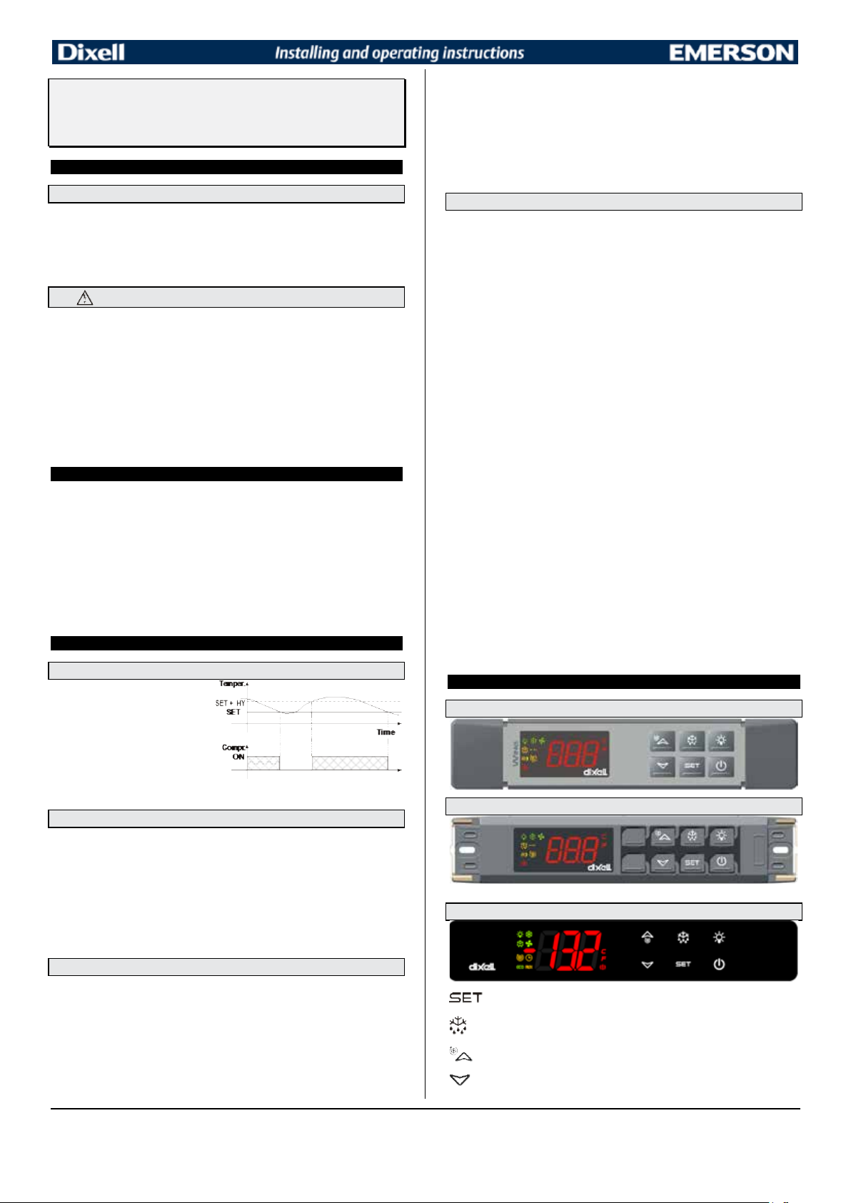
Digital controller with defrost, fans and auxiliary relay
The regulation is performed according to
again.
XW60LR –XW60LRH
1. GENERAL WARNING
1.1 PLEASE READ BEFORE USING THIS MANUAL
• This manual is part of the product and should be kept near the instrument for easy and quick
reference.
• The instrument shall not be used for purposes different from those described hereunder. It cannot be
used as a safety device.
• Check the application limits before proceeding.
• Dixell Srl reserves the right to change the composition of its products, even without notice, ensuring
the same and unchanged functionality.
1.2
• Check the supply voltage is correct before connecting the instrument.
• Do not expose to water or moisture: use the controller only within the operating limits avoiding sudden
• Warning: disconnect all electrical connections before any kind of maintenance.
• Fit the probe where it is not accessible by the End User. The instrument must not be opened.
• In case of failure or faulty operation send the instrument back to the distributor or to “Dixell S.r.l.” (see
• Consider the maximum current which can be applied to each relay (see Technical Data).
• Ensure that the wires for probes, loads and the power supply are separated and far enough from each
• In case of applications in industrial environments, the use of mains filters (our mod. FT1) in parallel
• Dixell Srl reserves the right to change the composition of its products, even without notice, ensuring
2. GENERAL DESCRIPTION
Models XW60LR, XW60LRH , format 38x185mm, are microprocessor based controller, suitable for
applications on medium or low temperature ventilated refrigerating units. It has 4 relay outputs to
control compressor, fan and defrost, which can be either electrical or reverse cycle (hot gas) It could
be provided with a Real Time Clock which allows programming of up to 6 daily defrost cycles, divided
into holidays and workdays. A “Day and Night” function with two different set points is fitted for energy
saving. It is also provided with up to three NTC or PTC probe inputs, the first one for temperature
control, the second one, to be located onto the evaporator, to control the defrost termination
temperature and to managed the fan. Third probe can operates as digital input.
The HOT KEY output allows to connect the unit, by means of the external module XJ485-CX, to a
network line ModBUS-RTU compatible such as the dIXEL monitoring units of X-WEB family. It
allows to program the controller by means the HOT KEY programming keyboard.
The instrument is fully configurable through special parameters that can be easily programmed
through the keyboard.
3. CONTROLLING LOADS
3.1 COMPRESSOR
the temperature measured by the
thermostat probe with a positive
differential from the set point: if the
temperature increases and reaches set
point plus differential the compressor is
started and then turned off when the
temperature reaches the set point value
In case of fault in the thermostat probe the start and stop of the compressor are timed through
parameters “COn” and “COF”.
3.2 DEFROST
Two defrost modes are available through the “tdF” parameter: defrost through electrical heater (tdF =
EL) and hot gas defrost (tdF = in).
The defrost interval depends on the presence of the RTC (optional). If the RTC is present is controlled
by means of parameter “EdF”:
- with EdF=in the defrost is made every “IdF” time – standard way for controller without RTC.
- with EdF = “rtc”, the defrost is made in real time depending on the hours set in the parameters
Other parameters are used to control defrost cycles: its maximum length (MdF) and two defrost
modes: timed or controlled by the evaporator’s probe (P2P).
At the end of defrost dripping time is started, its length is set in the Fdt parameter. With Fdt =0 the
dripping time is disabled.
3.3 CONTROL OF EVAPORATOR FANS
The fan control mode is selected by means of the “FnC” parameter:
FnC = C_n: fans will switch ON and OFF with the compressor and not run during defrost;
FnC = o_n fans will run even if the compressor is off, and not run during defrost;
After defrost, there is a timed fan delay allowing for drip time, set by means of the “Fnd” parameter.
FnC = C_Y fans will switch ON and OFF with the compressor and run during defrost;
FnC = o_Y fans will run continuously also during defrost
An additional parameter “FSt” provides the setting of temperature, detected by the evaporator probe,
above which the fans are always OFF. This is used to make sure circulation of air only if his
temperature is lower than set in “FSt”.
1592027550 XW60LR - XW60LRH RTC GB r2.0 18.03.2015 XW60LR – XW60LRH 1/6
SAFETY PRECAUTIONS
temperature changes with high atmospheric humidity to prevent formation of condensation
address) with a detailed description of the fault.
other, without crossing or intertwining.
with inductive loads could be useful.
the same and unchanged functionality.
Ld1..Ld6 on workdays and in Sd1…Sd6 in holidays;
management
3.3.1 Forced activation of fans
This function managed by the Fct parameter is designed to avoid short cycles of fans, that could
happen when the controller is switched on or after a defrost, when the room air warms the evaporator.
Functioning: if the difference of temperature between the evaporator and the room probes is more
than the value of the Fct parameter, the fans are switched on. With Fct=0 the function is disabled.
3.3.2 Cyclical activation of the fans with compressor off.
When Fnc = c-n or c-Y (fans in parallel to the compressor), by means of the Fon and FoF parameters
the fans can carry out on and off cycles even if the compressor is switched off. When the compressor
is stopped the fans go on working for the Fon time. With Fon =0 the fans remain always off, when the
compressor is off.
3.4 AUXILIARY RELAY CONFIGURATION - TERM.3-5, PAR. OA3
The functioning of the auxiliary relay (terminals. 3-5) can be set by the oA3 parameter, according to
the kind of application. In the following paragraph the possible setting:
3.4.1 Light relay - oA3= Lig
With oA3 = Lig, the 3-5 relay is set as light. It is activated by key or when i1F = dor.
3.4.2 Alarm relay – oA3= AUS
There are 2 possibilities:
a. Activation via digital input (oA3= AUS, i1F or i2F = AUS)
With oA3 = AUS and i2F or i1F = AUS the relay 3-5 is activated via digital input and remains ON until
the digital input is activated or is silenced by pressing any key.
b. Auxiliary thermostat (es. anti-sweat heaters)
Parameters involved:
- ACH Type of regulation: heating/cooling;
- SAA Set point auxiliary relay
- SHy Differential for auxiliary relay
- ArP Probe for auxiliary relay
- Sdd Auxiliary output off during defrost
By means of these 5 parameters the functioning of the auxiliary relay can be set.
NOTE: Set oA3=AUS and ArP= nP (no probe for auxiliary output).
In this case the relay 3-5 can be activated only by digital input with i1F or i2F = AUS.
3.4.3 On/off relay – oA3 = onF
In this case the relay is activated when the controller is turned on and de-activated when the controller
is in stand-by mode.
3.4.4 Neutral zone regulation
With oA3 = db the relay 3-5 can control a heater element to perform a neutral zone action.
oA3 cut in = SET-HY
oA3 cut out = SET
3.4.5 Alarm relay
With oA3 = ALr the relay 3-5 operates as alarm relay. It is activated every time an alarm happens. Its
status depends on the tbA parameter:
With “tbA = y”, the relay is silenced by pressing any key.
With “tbA = n”, the alarm relay remains on until the alarm condition recovers.
3.4.6 Night blind management during energy saving cycles
With oA3 = HES, the relay 3-5 operates to manage the night blind: the relay is energised when the
energy saving cycle is activated, by digital input, frontal button or RTC (optional).
4. FRONT PANEL COMMANDS
4.1 XW60LR - STANDARD FRONTAL PANEL
4.2 XW60LR - STEEL FINISHING
4.3 XW60LRH
: To display target set point; in programming mode it selects a parameter or confirm an
operation.
(DEF) To start a manual defrost
(UP): To see the max. stored temperature; in programming mode it browses the parameter
codes or increases the displayed value.
(DOWN) To see the min stored temperature; in programming mode it browses the parameter
codes or decreases the displayed value.
79
Page 80
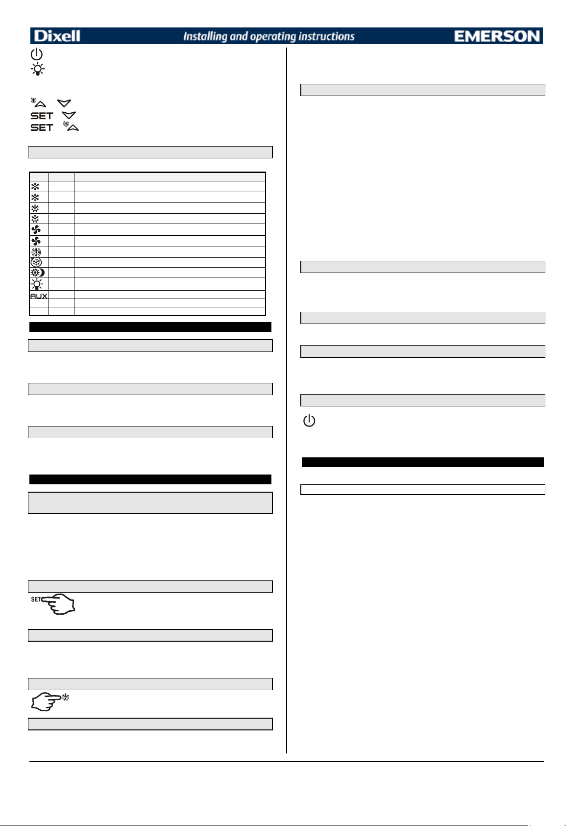
To switch the instrument off, if onF = oFF.
LED
MODE
FUNCTION
ON
Compressor enabled
Flashing
Anti-short cycle delay enabled
ON
Defrost enabled
Flashing
Drip time in progress
ON
Fans enabled
Flashing
Fans delay after defrost in progress.
ON
An alarm is occurring
ON
Continuous cycle is running
ON
Energy saving enabled
ON
Light on
ON
Auxiliary relay on
°C
ON
Measurement unit
°C
Flashing
Programming phase
1. Push and immediately release the SET key: the display will show the Set
2. Push and immediately release the SET key or wait for 5 seconds to
Push the DEF key for more than 2 seconds and a manual defrost will start.
With “onF = oFF”, pushing the ON/OFF key, the instrument is switched off. The “OFF”
To switch the light, if oA3 = Lig.
KEY COMBINATIONS:
+
To lock & unlock the keyboard.
+ To enter in programming mode.
+
4.4 USE OF LEDS
Each LED function is described in the following table.
5. MAX & MIN TEMPERATURE MEMORIZATION
5.1 HOW TO SEE THE MIN TEMPERATURE
1. Press and release the n
2. The “Lo” message will be displayed followed by the minimum temperature recorded.
3. By pressing the n
5.2 HOW TO SEE THE MAX TEMPERATURE
1. Press and release the o
2. The “Hi” message will be displayed followed by the maximum temperature recorded.
3. By pressing the o
5.3 HOW TO RESET THE MAX AND MIN TEMPERATURE RECORDED
1. Hold press the SET key for more than 3s, while the max. or min temperature is displayed. (rSt
message will be displayed)
2. To confirm the operation the “rSt” message starts blinking and the normal temperature will be
displayed.
6. MAIN FUNCTIONS
6.1 TO SET THE CURRENT TIME AND DAY (ONLY FOR INSTRUMENTS
WITH RTC)
When the instrument is switched on, it’s necessary to program the time and day.
1. Enter the Pr1 programming menu, by pushing the SET + n
2. The rtc parameter is displayed. Push the SET key to enter the real time clock menu.
3. The Hur (hour) parameter is displayed.
4. Push the SET and set current hour by the UP and Down keys, then push SET to confirm
the value..
5. Repeat the same operations on the Min (minutes) and dAy (day) parameters.
To exit: Push SET+UP keys or wait for 15 sec without pushing any keys.
6.2 HOW TO SEE THE SET POINT
display the probe value again.
6.3 HOW TO CHANGE THE SET POINT
1. Push the SET key for more than 2 seconds to change the Set point value;
2. The value of the set point will be displayed and the “°C” LED starts blinking;
3. To change the Set value push the o
4. To memorise the new set point value push the SET key again or wait 10s.
6.4 HOW TO START A MANUAL DEFROST
6.5 HOW TO CHANGE A PARAMETER VALUE
To change the parameter’s value operate as follows:
1. Enter the Programming mode by pressing the Set + n
2. Select the required parameter. Press the “SET” key to display its value
To return to the room temperature display.
key.
key again or by waiting 5s the normal display will be restored.
key.
key again or by waiting 5s the normal display will be restored.
keys for 3s.
point value;
or n
arrows within 10s.
keys for 3s (the “°C” LED starts blinking).
3. Use “UP” or “DOWN” to change its value.
4. Press “SET” to store the new value and move to the following parameter.
To exit: Press SET + UP or wait 15s without pressing a key.
NOTE: the set value is stored even when the procedure is exited by waiting the time-out to expire.
6.6 THE HIDDEN MENU
The hidden menu Includes all the parameters of the instrument.
6.6.1 HOW TO ENTER THE HIDDEN MENU
1. Enter the Programming mode by pressing the Set + n
blinking).
2. Released the keys, then push again the Set+n
displayed immediately followed from the HY parameter.
NOW YOU ARE IN THE HIDDEN MENU.
3. Select the required parameter.
4. Press the “SET” key to display its value
or n
5. Use o
6. Press “SET” to store the new value and move to the following parameter.
To exit: Press SET + o
NOTE1: if none parameter is present in Pr1, after 3s the “noP” message is displayed. Keep the keys
pushed till the Pr2 message is displayed.
NOTE2: the set value is stored even when the procedure is exited by waiting the time-out to expire.
6.6.2 HOW TO MOVE A PARAMETER FROM THE HIDDEN MENU TO THE
FIRST LEVEL AND VICEVERSA.
Each parameter present in the HIDDEN MENU can be removed or put into “THE FIRST LEVEL” (user
level) by pressing “SET + n
In HIDDEN MENU when a parameter is present in First Level the decimal point is on.
to change its value.
or wait 15s without pressing a key.
”.
keys for 3s (the “°C” or “°F” LED starts
keys for more than 7s. The Pr2 label will be
6.7 HOW TO LOCK THE KEYBOARD
1. Keep pressed for more than 3 s the UP + DOWN keys.
2. The “POF” message will be displayed and the keyboard will be locked. At this point it will be
possible only to see the set point or the MAX o Min temperature stored
3. If a key is pressed more than 3s the “POF” message will be displayed.
6.8 TO UNLOCK THE KEYBOARD
Keep pressed together for more than 3s the o and n
displayed.
keys, till the “Pon” message will be
6.9 THE CONTINUOUS CYCLE
When defrost is not in progress, it can be activated by holding the “o
seconds. The compressor operates to maintain the “ccS” set point for the time set through the “CCt”
parameter. The cycle can be terminated before the end of the set time using the same activation key
“
” for 3 seconds.
o
” key pressed for about 3
6.10 THE ON/OFF FUNCTION
message is displayed. In this configuration, the regulation is disabled.
To switch the instrument on, push again the ON/OFF key.
WARNING: Loads connected to the normally closed contacts of the relays are always supplied
and under voltage, even if the instrument is in stand by mode.
7. PARAMETERS
rtc Real time clock menu (only for controller with RTC): to set the time and date and defrost start
time.
REGULATION
Hy Differential: (0,1 ÷ 25,5°C / 1÷255 °F) Intervention differential for set point. Compressor Cut IN is
Set Point + differential (Hy). Compressor Cut OUT is when the temperature reaches the set
point.
LS Minimum set point: (- 50°C÷SET/-58°F÷SET): Sets the minimum value for the set point.
US Maximum set point: (SET÷110°C/ SET÷230°F). Set the maximum value for set point.
Ot Thermostat probe calibration: (-12.0÷12.0°C; -120÷120°F) allows to adjust possible offset of
the thermostat probe.
P2P Evaporator probe presence: n= not present: the defrost stops by time; y= present: the defrost
stops by temperature.
OE Evaporator probe calibration: (-12.0÷12.0°C; -120÷120°F). allows to adjust possible offset of
the evaporator probe.
P3P Third probe presence (P3): n= not present:, the terminals 13-14 operate as digital input.; y=
present:, the terminals 13-14 operate as third probe.
O3 Third probe calibration (P3): (-12.0÷12.0°C; -120÷120°F). allows to adjust possible offset of the
third probe.
OdS Outputs activation delay at start up: (0÷255min) This function is enabled at the initial start up
of the instrument and inhibits any output activation for the period of time set in the parameter.
AC Anti-short cycle delay: (0÷50 min) minimum interval between the compressor stop and the
following restart.
rtr Percentage of the second and first probe for regulation (0÷100; 100 = P1, 0 = P2 ): it allows
to set the regulation according to the percentage of the first and second probe, as for the
following formula (rtr(P1-P2)/100 + P2).
CCt Compressor ON time during continuous cycle: (0.0÷24.0h; res. 10min) Allows to set the
length of the continuous cycle: compressor stays on without interruption for the CCt time. Can be
used, for instance, when the room is filled with new products.
CCS Set point for continuous cycle: (-50÷150°C) it sets the set point used during the continuous
cycle.
COn Compressor ON time with faulty probe: (0÷255 min) time during which the compressor is
active in case of faulty thermostat probe. With COn=0 compressor is always OFF.
COF Compressor OFF time with faulty probe: (0÷255 min) time during which the compressor is
OFF in case of faulty thermostat probe. With COF=0 compressor is always active.
1592027550 XW60LR - XW60LRH RTC GB r2.0 18.03.2015 XW60LR – XW60LRH 2/6
80
Page 81
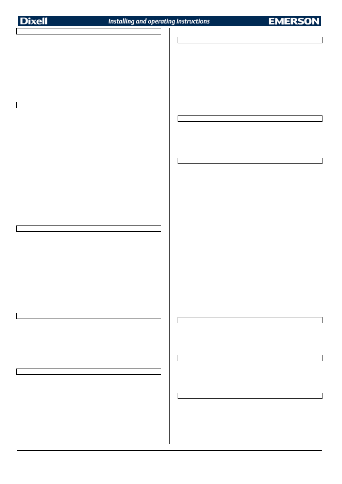
DISPLAY
CF Temperature measurement unit: °C=Celsius; °F=Fahrenheit. WARNING: When the
measurement unit is changed the SET point and the values of the parameters Hy, LS, US, Ot,
ALU and ALL have to be checked and modified if necessary).
rES Resolution (for °C): (in = 1°C; dE = 0.1 °C) allows decimal point display.
Lod Instrument display: (P1; P2, P3, P4, SET, dtr): it selects which probe is displayed by the
instrument: P1 = Thermostat probe; P2 = Evaporator probe; P3 = Third probe(only for model with
this option enabled); P4 = NOT SET IT, SET = set point; dtr = percentage of visualization.
rEd X- REP display (optional): (P1; P2, P3, P4, SET, dtr): it selects which probe is displayed by X-
REP: P1 = Thermostat probe; P2 = Evaporator probe; P3 = Third probe(only for model with this
option enabled); P4 = NOT SET IT, SET = set point; dtr = percentage of visualization.
dLy Display delay: (0 ÷20.0m; resul. 10s) when the temperature increases, the display is updated of
1 °C/1°F after this time.
dtr Percentage of the second and first probe for visualization when Lod = dtr (0÷100; 100 =
P1, 0 = P2 ): if Lod = dtr it allows to set the visualization according to the percentage of the first
and second probe, as for the following formula (dtr(P1-P2)/100 + P2).
DEFROST
EdF Defrost mode (only for controller with RTC):
rtc = Real Time Clock mode. Defrost time follows Ld1÷Ld6 parameters on workdays and
Sd1÷Sd6 on holidays.
in = interval mode. The defrost starts when the time “Idf” is expired.
tdF Defrost type: EL = electrical heater; in = hot gas
dFP Probe selection for defrost termination: nP = no probe; P1 =thermostat probe; P2 =
evaporator probe; P3 =configurable probe; P4 = NOT SET IT.
dtE Defrost termination temperature: (-50÷50 °C/ -58÷122°F) sets the temperature measured by
the evaporator probe, which causes the end of defrost.
IdF Interval between defrost cycles: (0÷120h) Determines the time interval between the beginning
of two defrost cycles.
MdF (Maximum) length for defrost: (0÷255min) When P2P = n, (not evaporator probe: timed
defrost) it sets the defrost duration, when P2P = y (defrost end based on temperature) it sets the
maximum length for defrost.
dSd Start defrost delay: ( 0÷59min) This is useful when different defrost start times are necessary to
avoid overloading the plant.
dFd Temperature displayed during defrost: (rt = real temperature; it = temperature at defrost start;
SEt = set point; dEF = “dEF” label)
dAd MAX display delay after defrost: (0÷120min). Sets the maximum time between the end of
defrost and the restarting of the real room temperature display.
Fdt Drip time: (0÷120 min) time interval between reaching defrost termination temperature and the
restoring of the control’s normal operation. This time allows the evaporator to eliminate water
drops that might have formed due to defrost.
dPo First defrost after start-up: (y = immediately; n = after the IdF time)
dAF Defrost delay after continuous cycle: (0÷23.5h) time interval between the end of the fast
freezing cycle and the following defrost related to it.
FANS
FnC Fans operating mode: C-n= runs with the compressor, OFF during defrost;
o-n = continuous mode, OFF during defrost;
C-Y = runs with the compressor, ON during defrost;
o-Y = continuous mode, ON during defrost;
Fnd Fans delay after defrost: (0÷255min) Interval between end of defrost and evaporator fans start.
Fct Temperature differential avoiding short cycles of fans (0÷59°C; Fct=0 function disabled). If
the difference of temperature between the evaporator and the room probes is more than the
value of the Fct parameter, the fans are switched on.
FSt Fans stop temperature: (-50÷50°C/122°F) setting of temperature, detected by evaporator
probe, above which fans are always OFF.
Fon Fan ON time: (0÷15 min) with Fnc = C_n or C_y, (fan activated in parallel with compressor). it
sets the evaporator fan ON cycling time when the compressor is off. With Fon =0 and FoF ≠ 0
the fan are always off, with Fon=0 and FoF =0 the fan are always off.
FoF Fan OFF time: (0÷15 min) with Fnc = C_n or C_y, (fan activated in parallel with compressor). it
sets the evaporator fan off cycling time when the compressor is off. With Fon =0 and FoF ≠ 0 the
fan are always off, with Fon=0 and FoF =0 the fan are always off.
FAP Probe selection for fan management: nP = no probe; P1 =thermostat probe; P2 = evaporator
probe; P3 =configurable probe; P4 = NOT SET IT.
AUXILIARY RELAY CONFIGURATION (terms. 3-5) – oA3 = AUS
ACH Kind of regulation for auxiliary relay: Ht = heating; CL = cooling
SAA Set Point for auxiliary relay: (-50,0÷110,0°C; -58÷230°F) it defines the room temperature set
point to switch auxiliary relay.
SHy Differential for auxiliary output: (0,1 ÷ 25,5°C / 1÷255 °F) Intervention differential for auxiliary
output set point.
With ACH = cL AUX Cut in is SAA + SHy; . AUX Cut out is SAA
With ACH = Ht AUX Cut in is SAA - SHy; . AUX Cut out is SAA
ArP Probe selection for auxiliary: nP = no probe, the auxiliary relay is switched only by button; P1
= Probe 1; P2 = Probe 2; P3 = Probe 3; P4 = NOT SET IT.
Sdd Auxiliary relay off during defrost: n = the auxiliary relay 3-5 operates during defrost.
y = the auxiliary relay 3-5 is switched off during defrost.
ALARMS
ALP Probe selection for alarm: nP = no probe, the temperature alarms are disabled; P1 = Probe 1;
P2 = Probe 2; P3 = Probe 3; P4 = NOT SET IT.
ALC Temperature alarms configuration: (Ab; rE)
Ab= absolute temperature: alarm temperature is given by the ALL or ALU values. rE =
temperature alarms are referred to the set point. Temperature alarm is enabled when the
temperature exceeds the “SET+ALU” or “SET-ALL” values.
ALU MAXIMUM temperature alarm: (SET÷110°C; SET÷230°F) when this temperature is reached
the alarm is enabled, after the “ALd” delay time.
ALL Minimum temperature alarm: (-50.0 ÷ SET °C; -58÷230°F when this temperature is reached
the alarm is enabled, after the “ALd” delay time.
AFH Differential for temperature alarm/ fan recovery: (0,1÷25,5°C; 1÷45°F) Intervention
differential for recovery of temperature alarm. It’s also used for the restart of the fan when the
FSt temperature is reached
ALd Temperature alarm delay: (0÷255 min) time interval between the detection of an alarm
condition and alarm signalling.
dAO Exclusion of temperature alarm at start-up: (from 0.0 min to 23.5h) time interval between the
detection of the temperature alarm condition after instrument power on and alarm signalling.
CONDENSER TEMPERATURE ALARM
AP2 Probe selection for temperature alarm of condenser: nP = no probe; P1 =thermostat probe;
P2 = evaporator probe; P3 =configurable probe; P4 = NOT SET IT.
AL2 Low temperature alarm of condenser: (-55÷150°C) when this temperature is reached the LA2
alarm is signalled, possibly after the Ad2 delay.
Au2 High temperature alarm of condenser: (-55÷150°C) when this temperature is reached the HA2
alarm is signalled, possibly after the Ad2 delay.
AH2 Differential for temperature condenser alarm recovery: (0,1÷25,5°C; 1÷45°F)
Ad2 Condenser temperature alarm delay: (0÷255 min) time interval between the detection of the
condenser alarm condition and alarm signalling.
dA2 Condenser temperature alarm exclusion at start up: (from 0.0 min to 23.5h, res. 10min)
bLL Compressor off with low temperature alarm of condenser: n = no: compressor keeps on
working; Y = yes, compressor is switched off till the alarm is present, in any case regulation
restarts after AC time at minimum.
AC2 Compressor off with high temperature alarm of condenser: n = no: compressor keeps on
working; Y = yes, compressor is switched off till the alarm is present, in any case regulation
restarts after AC time at minimum.
AUXILIARY RELAY
tbA Alarm relay silencing (with oA3 =ALr):
n= silencing disabled: alarm relay stays on till alarm condition lasts,
y =silencing enabled: alarm relay is switched OFF by pressing a key during an alarm
oA3 Fourth relay configuration (3-5): dEF, FAn: do not select it!. ALr: alarm; Lig: light; AuS:
Auxiliary relay; onF: always on with instrument on; db= neutral zone; cP2 = second compressor;
dF2: do not select it!;. HES:. night blind.
AoP Alarm relay polarity: it set if the alarm relay is open or closed when an alarm happens. CL=
terminals 1-4 closed during an alarm; oP = terminals 1-4 open during an alarm
DIGITAL INPUTS
i1P Digital input 1 polarity (13-14): oP: the digital input is activated by opening the contact; CL: the
digital input is activated by closing the contact.
i1F Digital input 1 configuration (13-14): EAL= external alarm: “EA” message is displayed; bAL=
serious alarm “CA” message is displayed. PAL= pressure switch alarm, “CA” message is
displayed; dor= door switch function; dEF= activation of a defrost cycle; AUS=not enabled; Htr=
kind of action inversion (cooling – heating); FAn= not set it; ES= Energy saving; HdF = Holiday
defrost (enable only with RTC); onF = to switch the controller off.
did (0÷255 min) with i1F= EAL or i1F = bAL digital input alarm delay (13-14): delay between the
detection of the external alarm condition and its signalling.
with i1F= dor: door open signalling delay
with i1F= PAL: time for pressure switch function: time interval to calculate the number of the
pressure switch activation.
nd
i2P 2
digital input polarity (13-19): oP: the digital input is activated by opening the contact; CL:
the digital input is activated by closing the contact.
nd
i2F 2
digital input configuration (13-19): EAL= external alarm: “EA” message is displayed; bAL=
serious alarm “CA” message is displayed. PAL= pressure switch alarm, “CA” message is
displayed; dor= door switch function; dEF= activation of a defrost cycle; AUS=not enabled; Htr=
kind of action inversion (cooling – heating); FAn= not set it; ES= Energy saving; HdF = Holiday
defrost (enable only with RTC); onF = to switch the controller off.
d2d (0÷255 min) with i2F= EAL or i2F= bAL 2
the detection of the external alarm condition and its signalling.
with i2F= dor: door open signalling delay
with i2F= PAL: time for pressure switch function: time interval to calculate the number of the
pressure switch activation.
nPS Pressure switch number: (0
interval, before signalling the alarm event (I2F= PAL).
If the nPS activation in the did time is reached, switch off and on the instrument to restart
normal regulation.
odc Compressor and fan status when open door: no = normal; Fan = Fan OFF; CPr =
Compressor OFF; F_C = Compressor and fan OFF.
rrd Outputs restart after doA alarm: no= outputs not affected by the doA alarm; yES = outputs
restart with the doA alarm.
HES Temperature increase during the Energy Saving cycle:
(-30,0°C
÷30,0°C) it sets the increasing value of the set point during the Energy Saving cycle.
÷15) Number of activation of the pressure switch, during the “did”
nd
digital input alarm delay (13-19): delay between
TO SET CURRENT TIME AND WEEKLY HOLIDAYS (ONLY FOR MODELS WITH RTC)
Hur Current hour (0 ÷ 23 h)
Min Current minute (0 ÷ 59min)
dAY Current day (Sun ÷ SAt)
Hd1 First weekly holiday (Sun ÷ nu) Set the first day of the week which follows the holiday times.
Hd2 Second weekly holiday (Sun ÷ nu) Set the second day of the week which follows the holiday
times.
N.B. Hd1,Hd2 can be set also as “nu” value (Not Used).
TO SET ENERGY SAVING TIMES (ONLY FOR MODELS WITH RTC)
ILE Energy Saving cycle start during workdays: (0 ÷ 23h 50 min.) During the Energy Saving
cycle the set point is increased by the value in HES so that the operation set point is SET +
HES.
dLE Energy Saving cycle length during workdays: (0 ÷ 24h 00 min.) Sets the duration of the
Energy Saving cycle on workdays.
ISE Energy Saving cycle start on holidays. (0 ÷ 23h 50 min.)
dSE Energy Saving cycle length on holidays (0 ÷ 24h 00 min.)
TO SET DEFROST TIMES (ONLY FOR MODELS WITH RTC)
Ld1÷Ld6 Workday defrost start (0 ÷ 23h 50 min.) These parameters set the beginning of the 6
programmable defrost cycles during workdays. Ex. When Ld2 = 12.4 the second defrost starts at
12.40 during workdays.
Sd1÷Sd6 Holiday defrost start (0 ÷ 23h 50 min.) These parameters set the beginning of the 6
programmable defrost cycles on holidays. Ex. When Sd2 = 3.4 the second defrost starts at 3.40
on holidays.
N.B. :To disable a defrost cycle set it to “nu”(not used). Ex. If Ld6=nu ; the sixth defrost
cycle is disabled
1592027550 XW60LR - XW60LRH RTC GB r2.0 18.03.2015 XW60LR – XW60LRH 3/6
81
Page 82
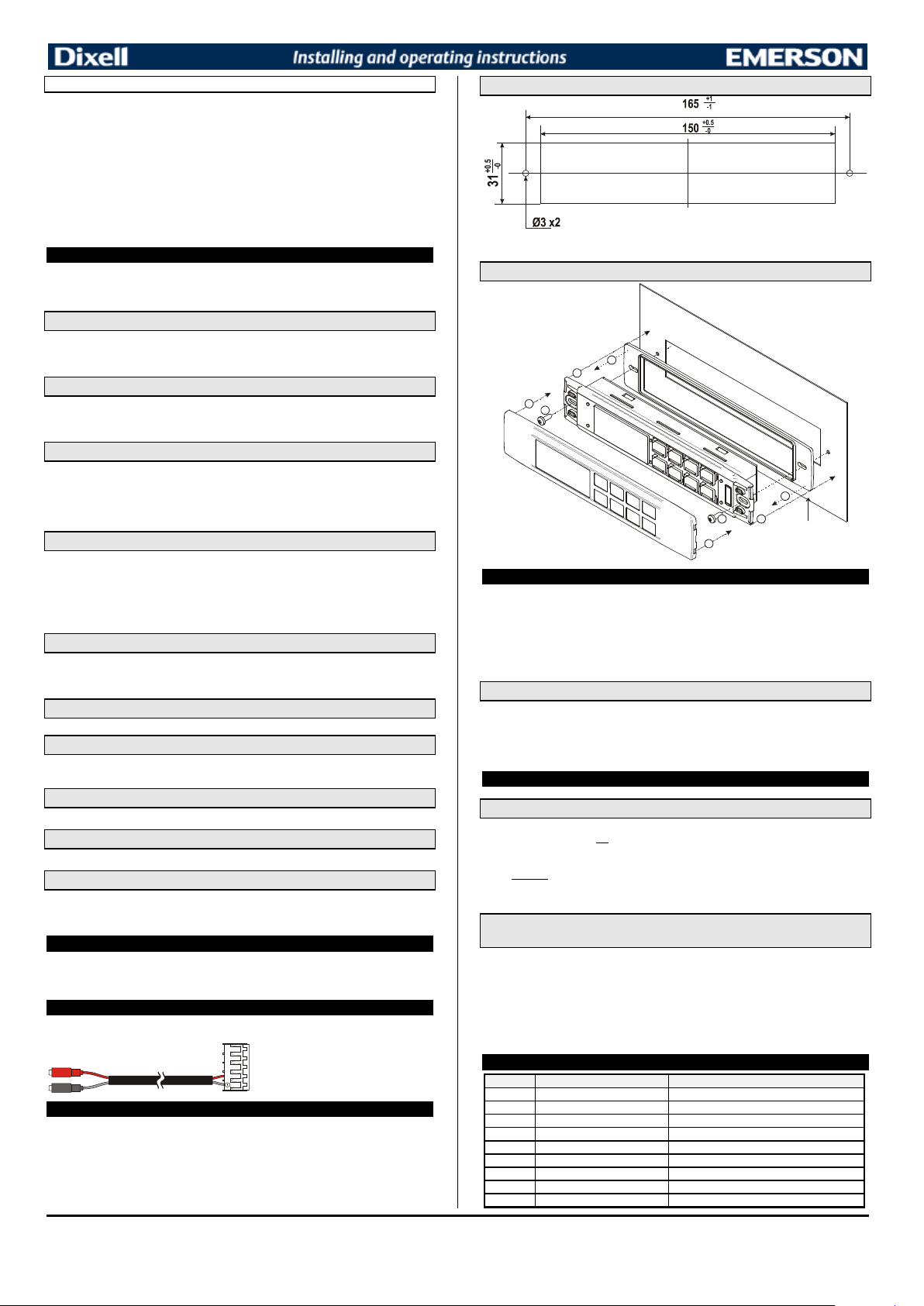
OTHER
To connect the X-REP to the instrument the
Message
Cause
Outputs
“P1”
Room probe failure
Compressor output acc. to par. “Con” and “COF”
“P2”
Second probe failure
Defrost end is timed
“P3”
Third probe failure
Outputs unchanged
“HA”
Maximum temperature alarm
Outputs unchanged.
“LA”
Minimum temperature alarm
Outputs unchanged.
"HA2"
Condenser high temperature
It depends on the “Ac2” parameter
"LA2"
Condenser low temperature
It depends on the “bLL” parameter
“dA”
Door open
Compressor and fans restarts
“EA”
External alarm
Output unchanged.
Adr Serial address (1÷244): Identifies the instrument address when connected to a ModBUS
compatible monitoring system.
PbC Type of probe: it allows to set the kind of probe used by the instrument: PbC = PBC probe, ntc
= NTC probe.
onF on/off key enabling: nu = disabled; oFF = enabled; ES = not set it.
dP1 Thermostat probe display
dP2 Evaporator probe display
dP3 Third probe display- optional.
rSE Real set point: it shows the set point used during the energy saving cycle or during the
continuous cycle.
rEL Software release for internal use.
Ptb Parameter table code: readable only.
8. DIGITAL INPUT
The first digital input is enabled with P3P = n.
With P3P = n and i1F = i2F the second digital input is disabled
The free voltage digital inputs are programmable by the “i1F” and i2F parameters.
8.1 GENERIC ALARM (i1F or i2F = EAL)
As soon as the digital input is activated the unit will wait for “did” time delay before signalling the
“EAL” alarm message. The outputs status don’t change. The alarm stops just after the digital input is
de-activated.
8.2 SERIOUS ALARM MODE (i1F or i2F = bAL)
When the digital input is activated, the unit will wait for “did” delay before signalling the “CA” alarm
message. The relay outputs are switched OFF. The alarm will stop as soon as the digital input is deactivated.
8.3 PRESSURE SWITCH (i1F or i2F = PAL)
If during the interval time set by “did” parameter, the pressure switch has reached the number of
activation of the “nPS” parameter, the “CA” pressure alarm message will be displayed. The
compressor and the regulation are stopped. When the digital input is ON the compressor is always
OFF. If the nPS activation in the did time is reached, switch off and on the instrument to restart
normal regulation.
8.4 DOOR SWITCH INPUT (i1F or i2F = dor)
It signals the door status and the corresponding relay output status through the “odc” parameter: no =
normal (any change); Fan = Fan OFF; CPr = Compressor OFF; F_C = Compressor and fan OFF.
Since the door is opened, after the delay time set through parameter “did”, the door alarm is enabled,
the display shows the message “dA” and the regulation restarts is rtr = yES. The alarm stops as
soon as the external digital input is disabled again. With the door open, the high and low temperature
alarms are disabled.
8.5 START DEFROST (i1F or i2F = dEF)
It starts a defrost if there are the right conditions. After the defrost is finished, the normal regulation will
restart only if the digital input is disabled otherwise the instrument will wait until the “MdF” safety time
is expired.
8.6 SWITCH THE AUXILIARY RELAY (i1F or i2F = AUS)
With oA3 = AUS the digital input switched the status of the auxiliary relay
8.7 ENERGY SAVING (i1F or i2F = ES)
The Energy Saving function allows to change the set point value as the result of the SET+ HES
(parameter) sum. This function is enabled until the digital input is activated.
8.8 HOLIDAY DEFROST (i1F or i2F = HDF) –ONLY FOR MODELS WITH RTC
This function enabled the holiday defrost setting.
8.9 ON OFF FUNCTION (i1F or i2F = onF)
To switch the controller on and off.
8.10 DIGITAL INPUTS POLARITY
The digital input polarity depends on the “i1P” parameter.
i1P or i2P =CL: the input is activated by closing the contact.
i1P or i2P=OP: the input is activated by opening the contact
9. TTL SERIAL LINE – FOR MONITORING SYSTEMS
The TTL serial line, available through the HOT KEY connector, allows by means of the external
TTL/RS485 converter, XJ485-CX, to connect the instrument to a monitoring system ModBUS-RTU
compatible such as the X-WEB500/3000/300.
10. X-REP OUTPUT – OPTIONAL
As optional, an X-REP can be connected to the instrument, trough the HOY KEY connector. The XREP output EXCLUDES the serial connection.
following connectors must be used CAB51F(1m), CAB-52F(2m), CAB-55F(5m),
11.1 CUT OUT
XW60LRH: the holes are not required
11.2 STEEL FINISHING MOUNTING
1
2
4
3
1
2
3
4
RG-LX gascke
(optional)
12. ELECTRICAL CONNECTIONS
The instruments are provided with screw terminal block to connect cables with a cross section up to
2
2,5 mm
for the digital and analogue inputs. Relays and power supply have a Faston connection
(6,3mm). Heat-resistant cables have to be used. Before connecting cables make sure the power
supply complies with the instrument’s requirements. Separate the probe cables from the power supply
cables, from the outputs and the power connections. Do not exceed the maximum current allowed on
each relay, in case of heavier loads use a suitable external relay.
N.B. Maximum current allowed for all the loads is 20A.
12.1 PROBE CONNECTION
The probes shall be mounted with the bulb upwards to prevent damages due to casual liquid
infiltration. It is recommended to place the thermostat probe away from air streams to correctly
measure the average room temperature. Place the defrost termination probe among the evaporator
fins in the coldest place, where most ice is formed, far from heaters or from the warmest place during
defrost, to prevent premature defrost termination.
13. HOW TO USE THE HOT KEY
13.1 HOW TO PROGRAM A HOT KEY FROM THE INSTRUMENT (UPLOAD)
1. Program one controller with the front keypad.
2. When the controller is ON, insert the “Hot key” and push o
followed a by flashing “End”
3. Push “SET” key and the End will stop flashing.
4. Turn OFF the instrument remove the “Hot Key”, then turn it ON again.
NOTE: the “Err” message is displayed for failed programming. In this case push again o
want to restart the upload again or remove the “Hot key” to abort the operation.
key; the "uPL" message appears
key if you
13.2 HOW TO PROGRAM AN INSTRUMENT USING A HOT KEY
(DOWNLOAD)
1. Turn OFF the instrument.
2. Insert a programmed “Hot Key” into the 5 PIN receptacle and then turn the Controller ON.
3. Automatically the parameter list of the “Hot Key” is downloaded into the Controller memory,
the “doL” message is blinking followed a by flashing “End”.
4. After 10 seconds the instrument will restart working with the new parameters.
5. Remove the “Hot Key”..
NOTE the message “Err” is displayed for failed programming. In this case turn the unit off and then on
if you want to restart the download again or remove the “Hot key” to abort the operation.
14. ALARM SIGNALS
11. INSTALLATION AND MOUNTING
The controller shall be mounted on vertical panel, in a 150x31 mm hole, and fixed using two screws ∅
3 x 2mm (only for XW60LR).
XW60LR: to obtain an IP65 protection grade use the front panel rubber gasket (mod. RG-L). The
temperature range allowed for correct operation is 0 - 60 °C. Avoid places subject to strong vibrations,
corrosive gases, excessive dirt or humidity. The same recommendations apply to probes. Let the air
circulate by the cooling holes.
1592027550 XW60LR - XW60LRH RTC GB r2.0 18.03.2015 XW60LR – XW60LRH 4/6
82
Page 83
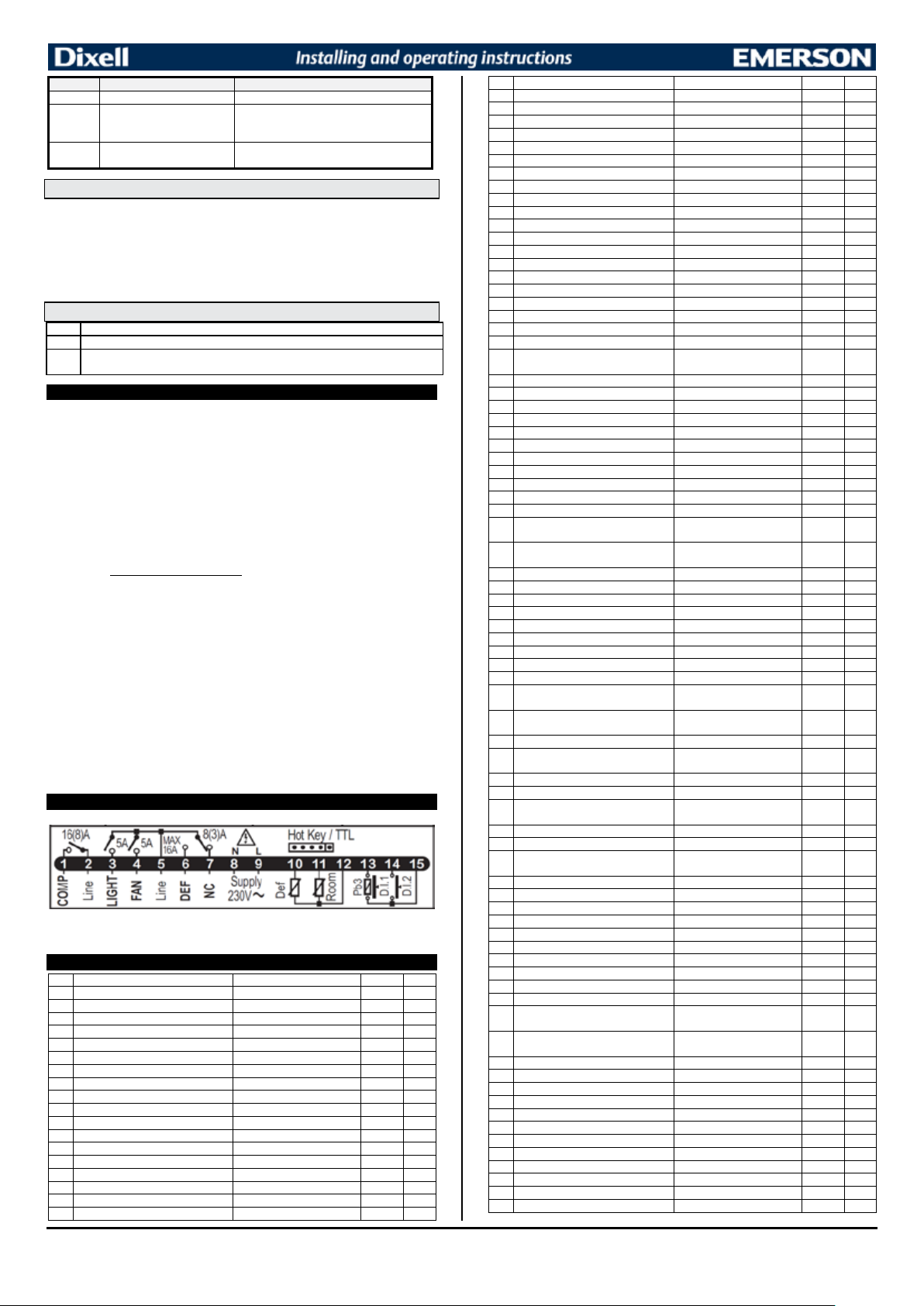
Message
Cause
Outputs
“CA”
Serious external alarm (i1F=bAL)
All outputs OFF.
“rtc”
Real time clock alarm
Alarm output ON; Other outputs unchanged;
Defrosts according to par. “IdF” Set real time clock
has to be set
rtF
Real time clock board failure
Alarm output ON; Other outputs unchanged;
Defrosts according to par. “IdF” Contact the service
Pon
Keyboard unlocked.
PoF
Keyboard locked
noP
In programming mode: none parameter is present in Pr1
On the display or in dP2, dP3, dP4: the selected probe is nor enabled
Label
Name
Range
°C/°F
Level
Set
Set point
LS - US
-5.0
- - -
rtc*
Real time clock menu
-
Pr1
Hy
Differential
(0,1°C ÷ 25,5°C)
2.0
Pr1
LS
Minimum set point
(-55,0°C ÷ SET)
-50.0
Pr2
US
Maximum set point
(SET ÷ 150,0°C)
110
Pr2
Ot
P1 probe calibration
(-12,0°C ÷ 12,0°C)
0.0
Pr1
P2P
P2 probe presence
n - Y
Y
Pr1
OE
P2 probe calibration
(-12,0°C ÷ 12,0°C)
0.0
Pr2
P3P
P3 probe presence
n - Y
n
Pr2
O3
P3 probe calibration
(-12,0°C ÷ 12,0°C)
0
Pr2
OdS
Outputs delay at start up
0 ÷ 255 (min.)
0
Pr2
AC
Anti-short cycle delay
0 ÷ 50 (min.)
1
Pr1
AC1
Second compressor start delay
0 ÷ 255 (sec.)
5
Pr2
rtr
P1-P2 percentage for regulation
0 ÷ 100 (100=P1 , 0=P2)
100
Pr2
CCt
Continuous cycle duration
0 ÷ 24H0(144)
0.0
Pr2
CCS
Set point for continuous cycle
(-55.0°C ÷ 150,0°C)
-5
Pr2
COn
Compressor ON time with faulty probe
0 ÷ 255 (min.)
15
Pr2
COF
Compressor OFF time with faulty probe
0 ÷ 255 (min.)
30
Pr2
Label
Name
Range
°C/°F
Level
CF
Temperature measurement unit
°C - °F
°C
Pr2
rES
Resolution
dE – in
dE
Pr1
Lod
Probe displayed
P1 - P2 - P3 - P4 - SEt – dtr
P1
Pr2
rEd2X-REP display
P1 - P2 - P3 - P4 - SEt – dtr
P1
Pr2
dLy
Display temperature delay
0 ÷ 20.0min (ris. 10 sec.)
0.0
Pr2
dtr
P1-P2 percentage for display
1 ÷ 99
50
Pr2
EdF*
Kind of interval for defrost
rtc÷in
in
Pr2
tdF
Defrost type
EL – in
EL
Pr1
dFP
Probe selection for defrost termination
nP - P1 - P2 – P3 - P4
P2
Pr2
dtE
Defrost termination temperature
(-55.0°C ÷ 50.0°C)
8.0
Pr1
IdF
Interval between defrost cycles
0 ÷ 120 (ore)
6
Pr1
MdF
(Maximum) length for defrost
0 ÷ 255 (min.)
30
Pr1
dSd
Start defrost delay
0 ÷ 255 (min.)
0
Pr2
dFd
Displaying during defrost
rt - it - SEt – dEF
it
Pr2
dAd
MAX display delay after defrost
0 ÷ 255 (min.)
30
Pr2
Fdt
Draining time
0 ÷ 255 (min.)
0
Pr2
dPo
First defrost after start-up
n – Y
n
Pr2
dAF
Defrost delay after fast freezing
0 ÷ 24.0h; ris. 10min
0.0
Pr2
Fnc
Fan operating mode
C_n - O_n - C_Y – O_Y
o-n
Pr1
Fnd
Fan delay after defrost
0 ÷ 255 (min.)
10
Pr1
Fct
Differential of temperature for forced
activation of fans
(0°C ÷ 50°C)
FSt
Fan stop temperature
(-55.0°C ÷ 50.0°C)
2
Pr1
Fon
Fan on time with compressor off
0÷15 (min.)
0
Pr2
FoF
Fan off time with compressor off
0÷15 (min.)
0
Pr2
FAP
Probe selection for fan management
nP - P1 - P2 - P3 – P4
P2
Pr2
ACH
Kind of action for auxiliary relay
CL – Ht
cL
Pr2
SAA
Set Point for auxiliary relay
(-55.0°C ÷ 150,0°C)
0,0
Pr2
SHy
Differential for auxiliary relay
(0,1°C ÷ 25,5°C)
2,0
Pr2
ArP
Probe selection for auxiliary relay
nP - P1 - P2 - P3 – P4
nP
Pr2
Sdd
Auxiliary relay operating during defrost
n – Y
n
Pr2
ALP
Alarm probe selection
nP - P1 - P2 - P3 – P4
P1
Pr2
ALc
Temperat. alarms configuration
rE – Ab
Ab
Pr2
ALU
MAXIMUM temperature alarm
ALc=rE: 0.0÷ 50.0°C
ALc=Ab: ALL÷150°C
ALL
Minimum temperature alarm
ALc = rE: 0.0÷50.0°C; ALc=Ab: -
55°C÷ALU
AFH
Differential for temperat. alarm recovery
(0,1°C ÷ 25,5°C)
2,0
Pr2
ALd
Temperature alarm delay
0 ÷ 255 (min.)
15
Pr2
dAO
Delay of temperature alarm at start up
0 ÷ 24.0 h ris. 10min
1,3
Pr2
AP2
Probe for temperat. alarm of condenser
nP - P1 - P2 - P3 – P4
P4
Pr2
AL2
Condenser for low temperat. alarm
(-55.0°C ÷ 150,0°C)
-40
Pr2
AU2
Condenser for high temperat. alarm
(-55.0°C ÷ 150,0°C)
110
Pr2
AH2
Differ. for condenser temp. alar. recovery
(0,1°C ÷ 25,5°C)
5
Pr2
Ad2
Condenser temperature alarm delay
0 ÷ 255 (min.)
15
Pr2
dA2
Delay of cond. temper. alarm at start up
0 ÷ 24H0(144)
1,3
Pr2
bLL
Compr. off for condenser low temperature
alarm
n – Y
AC2
Compr. off for condenser high
temperature alarm
n – Y
tbA
Alarm relay disabling
n – Y
y
Pr2
oA3
Third relay configuration
dEF - FAn - ALr - LiG - AUS OnF - db - CP2 - dF2 – HES
AoP
Alarm relay polarity
OP – CL
cL
Pr2
i1P
Digital input polarity
OP – CL
cL
Pr1
i1F
Digital input 1 configuration
EAL - bAL - PAL - dor - dEF -
AUS - Htr - FAn - ES-HdF – onF
did
Digital input alarm delay
0 ÷ 255 (min.)
15
Pr1
i2P
Digital input 2 polarity
OP – CL
cL
Pr2
i2F
Digital input 2 configuration
EAL - bAL - PAL - dor - dEF -
AUS - Htr - FAn - ES-HdF – onF
d2d
Digital input alarm delay
0 ÷ 255 (min.)
5
Pr2
nPS
Number of activation of pressure switch
0 ÷ 15
15
Pr2
odc
Compress and fan status when open door
no - FAn - CPr - F-C
F-c
Pr2
rrd
Regulation restart with door open alarm
n - Y
y
Pr2
HES
Differential for Energy Saving
(-30°C ÷ 30°C)
0
Pr2
Hur*
Current hour
Read only
-
Pr1
Min*
Current minute
Read only
-
Pr1
dAY*
Current day
Read only
-
Pr1
Hd1*
First weekly holiday
Sun ÷ SAt – nu
nu
Pr1
Hd2*
Second weekly holiday
Sun ÷ SAt – nu
nu
Pr1
ILE*
Energy Saving cycle start during
workdays
0 ÷ 23h5
dLE*
Energy Saving cycle length during
workdays
0 ÷ 24h0
ISE*
Energy Saving cycle start on holidays
0 ÷ 23h5
0.0
Pr1
dSE*
Energy Saving cycle length on holidays
0 ÷ 24h0
0
Pr1
Ld1*
1stworkdays defrost start
0 ÷ 23H5;- nu
nu
Pr1
Ld2*
2ndworkdays defrost start
0 ÷ 23H5;- nu
nu
Pr1
Ld3*
3rdworkdays defrost start
0 ÷ 23H5;- nu
nu
Pr1
Ld4*
4thworkdays defrost start
0 ÷ 23H5;- nu
nu
Pr1
Ld5*
5thworkdays defrost start
0 ÷ 23H5;- nu
nu
Pr1
Ld6*
6thworkdays defrost start
0 ÷ 23H5;- nu
nu
Pr1
Sd1*
1stholiday defrost start
0 ÷ 23H5;- nu
nu
Pr1
Sd2*
2ndholiday defrost start
0 ÷ 23H5;- nu
nu
Pr1
Sd3*
3rdholiday defrost start
0 ÷ 23H5;- nu
nu
Pr1
Sd4*
4thholiday defrost start
0 ÷ 23H5;- nu
nu
Pr1
14.1 ALARM RECOVERY
Probe alarms P1”, “P2”, “P3” start some seconds after the fault in the related probe; they automatically
stop some seconds after the probe restarts normal operation. Check connections before replacing the
probe.
Temperature alarms “HA”, “LA” “HA2” and “LA2” automatically stop as soon as the temperature
returns to normal values.
Alarms “EA” and “CA” (with i1F=bAL) recover as soon as the digital input is disabled.
Real time clock alarm rtC, it stops as soon as the correct hour and day are set.
Real time clock alarm rtF, the clock board has to be replaced. Contact the service.
14.2 OTHER MESSAGES
15. TECHNICAL DATA
Housing: self extinguishing ABS.
Case: facia 38x185 mm; depth 40mm
Mounting : panel mounting in a 150x31 mm panel cut-out with
Protection: IP20;
Frontal protection: IP65 Only for XW60LR with frontal gasket mod RG-L or RG-LX.
Connections: Screw terminal block ≤1 mm
block
Power supply: 230Vac or. 110Vac ± 10%, 50/60Hz.
Power absorption: 7VA max.
Display: 3 digits, red LED, 14,2 mm high.
Inputs: Up to 4 NTC or PTC probes.
Digital inputs: free of voltage
Relay outputs: Total current on loads MAX. 20A
Other output : buzzer (optional)
Serial output : TTL as alternate to X-REP output
X-REP output : optional as alternate to TTL serial output
Communication protocol: Modbus - RTU
Data storing: on the non-volatile memory (EEPROM).
Internal clock back-up: 24 hours (only for model with RTC)
Kind of action: 1B; Pollution grade: normal; Software class: A.;
Over voltage Category: II
Operating temperature: 0÷60 °C; Storage temperature: -30÷85 °C.
Relative humidity: 20÷85% (no condensing)
Measuring and regulation range: NTC probe: -40÷110°C (-40÷230°F);
Resolution: 0,1 °C or 1 °F (selectable); Accuracy (ambient temp. 25°C): ±0,7 °C ±1 digit
Only for XW60LR: two screws.
2
2
≤ 2,5 mm
heat-resistant wiring for low voltage (110 or 230Vac).
compressor: relay SPST 20(8) A, 250Vac
light: relay SPST 5A, 250Vac
fans: relay SPST 5 A, 250Vac
defrost: relay SPST 8(3) A, 250Vac
PTC probe: -50÷150°C (-58÷302°F)
heat-resistant wiring for very low voltage, Screw terminal
∅3x2mm, distance between holes 165mm
16. CONNECTIONS
10 Pr2
110,0 Pr1
-50,0 Pr1
n Pr2
n Pr2
Lig Pr2
dor Pr1
Supply: 120Vac: connect to terminals 8-9.
NOTE: on models with X-REP option, connect the X-REP to the HOT KEY receptacle
17. DEFAULT SETTING VALUES
1592027550 XW60LR - XW60LRH RTC GB r2.0 18.03.2015 XW60LR – XW60LRH 5/6
EAL Pr2
0.0 Pr1
0 Pr1
83
Page 84
Label
Name
Range
°C/°F
Level
Sd5*
5thholiday defrost start
0 ÷ 23H5;- nu
nu
Pr1
Sd6*
6thholiday defrost start
0 ÷ 23H5;- nu
nu
Pr1
Adr
Serial address
1 ÷ 247
1
Pr2
PbC
Kind of probe
PtC - ntC
ntc
Pr2
onF
on/off key enabling
nu - OFF – ES
oFF
Pr2
dP1
Room probe display
Probe value
-
Pr2
dP2
Evaporator probe display
Probe value
-
Pr2
dP3
Third probe display
Probe value
-
Pr2
rSE
Real set
Read only
-
Pr2
rEL
Software release
Read only
1.8
Pr2
Ptb
Map code
Read only
Pr2
2 Only for model with X-REP output
* Only for model with real time clock
1592027550 XW60LR - XW60LRH RTC GB r2.0 18.03.2015 XW60LR – XW60LRH 6/6
84
Page 85
EPREL DATA
Model: CK7210 CK7310 CK7410 CF7210 CF7310 CF7410
Model type: Storage Storage Storage Storage Storage Storage
Use: Cooling Cooling Cooling Freezing Freezing Freezing
Type: Counter Cooler Counter Cooler Counter Cooler Counter Freezer Counter Freezer Counter Freezer
Light-/Heavy-duty: Heavy-duty Heavy-duty Heavy-duty Heavy-duty Heavy-duty Heavy-duty
Refrigerant: R600a R600a R600a R290 R290 R290
Refrigerant charge: (g.) 95 95 95 90 90 90
GWP: 3 3 3 3 3 3
AEC: 723 894 1445 2537 3197 3745
EEI: 31,2 33,1 48,1 70,9 71,5 72,6
Net. Volume Cooling: 205 358 476 / / /
Net. Volume Freezing: / / / 205 358 476
Model: BK210 BK310 UC5210 UC5310 UC5410 SK6210 SK6310 SK6410
Model type: Storage Storage Storage Storage Storage Storage Storage Storage
Use: Cooling Cooling Cooling Cooling Cooling Cooling Cooling Cooling
Type: Counter Cooler Counter Cooler Counter Cooler Counter Cooler Counter Cooler Counter Cooler Counter Cooler Counter Cooler
Light-/Heavy-duty: Heavy-duty Heavy-duty Heavy-duty Heavy-duty Heavy-duty Heavy-duty Heavy-duty Heavy-duty
Refrigerant: R600a R600a R600a R600a R600a R600a R600a R600a
Refrigerant charge: (g.) 95 95 85 85 95 95 95 95
GWP: 3 3 3 3 3 3 3 3
AEC: 708 1332 785 916 978 715 821 1398
EEI: 28 45,5 37,1 40,1 39,8 32,3 32,5 49,8
Net. Volume Cooling: 290 444 127 194 262 166 289 398
Net. Volume Freezing: / / / / / / / /
Model: SS7200 SS7300 SS8200 SS8300 PT1200 PT1300 PT1310
Model type: Saladette Saladette Saladette Saladette Storage Storage Storage
Use: Cooling Cooling Cooling Cooling Cooling Cooling Cooling
Type: Saladette Saladette Saladette Saladette Counter Cooler Counter Cooler Counter Cooler
Light-/Heavy-duty: Heavy-duty Heavy-duty Heavy-duty Heavy-duty Heavy-duty Heavy-duty Heavy-duty
Refrigerant: R600a R600a R600a R600a R600a R600a R600a
Refrigerant charge: (g.) 95 95 95 95 95 95 95
GWP: 3 3 3 3 3 3 3
AEC: 986 1022 1022 1168 847 1332 880
EEI: / / / / 33,5 45,5 34,8
Net. Volume Cooling: / / / / 290 444 290
Net. Volume Freezing: / / / / / / /
Tefcold A/S
Industrivej 25
DK-8800 Denmark
www.tefcold.com
CE-Declarations: www.tefcold.com
85
 Loading...