

Page 1
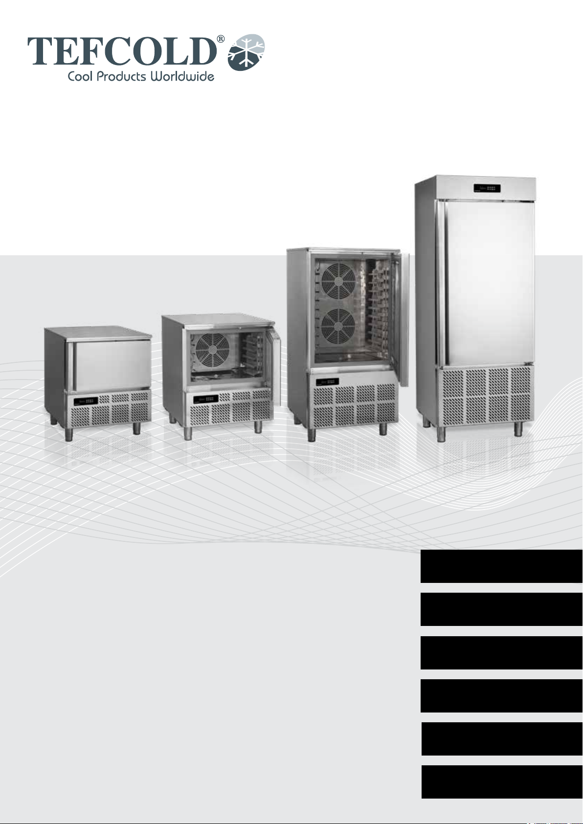
BLAST CHILLER/FREEZER
User Manual
EN
FR
IT
ES
PT
SL
3
13
25
37
49
61
Page 2

2
Page 3

CONTENTS
1.
2.
General information
Important safety instructions .................................................................................. 4
Unpacking and installation ..................................................................................... 4
Electrical connection .............................................................................................. 5
Start-up of the cabinet ........................................................................................... 5
Capacity ................................................................................................................. 5
Recommendations for use ..................................................................................... 5
Blast chilling cycle ................................................................................................. 6
Shock freezing cycle .............................................................................................. 6
Cleaning and maintenance .................................................................................... 6
Service ................................................................................................................... 7
Disposal ................................................................................................................. 7
Quick guide
3.
Daily quick guide ................................................................................................... 9
Thermostat XB570L / XB590L
Technical manual ................................................................................................. 73
3
Page 4
IMPORTANT SAFETY INSTRUCTIONS
1. To obtain full use of the cabinet, we recommend reading this instruction manual.
2. It is the user’s responsibility to operate the appliance in accordance with the instructions given.
3. Contact your dealer immediately in case of any malfunctions.
4. Place the cabinet in a dry and ventilated place.
5. Keep the cabinet away from strongly heat-emitting sources and do not expose it to direct sunlight.
6. Always keep in mind that all electrical devices are sources of potential danger.
7. Do not store inammable material such as thinner, gasoline etc. in the cabinet.
8. We declare that no asbestos nor any CFC are used in the construction.
9. The oil in the compressor does not contain PCB
ONLY FOR APPLIANCES WITH REFRIGERANT R290/R600a!
This appliance contains a ammable refrigerant, so make sure of good ventilation
around the appliance. Do not use mechanical devices when defrosting, this can cause
leakage of the cooling system. Do not use electrical appliances inside the refrigerated
storage compartment.
Any repair of the appliance should be carried out by a skilled technician (EN 60335-289: 2010).
UNPACKING AND INSTALLATION
Remove the wooden pallet and the packing. External surfaces are supplied with a protection foil,
which must be removed before installation.
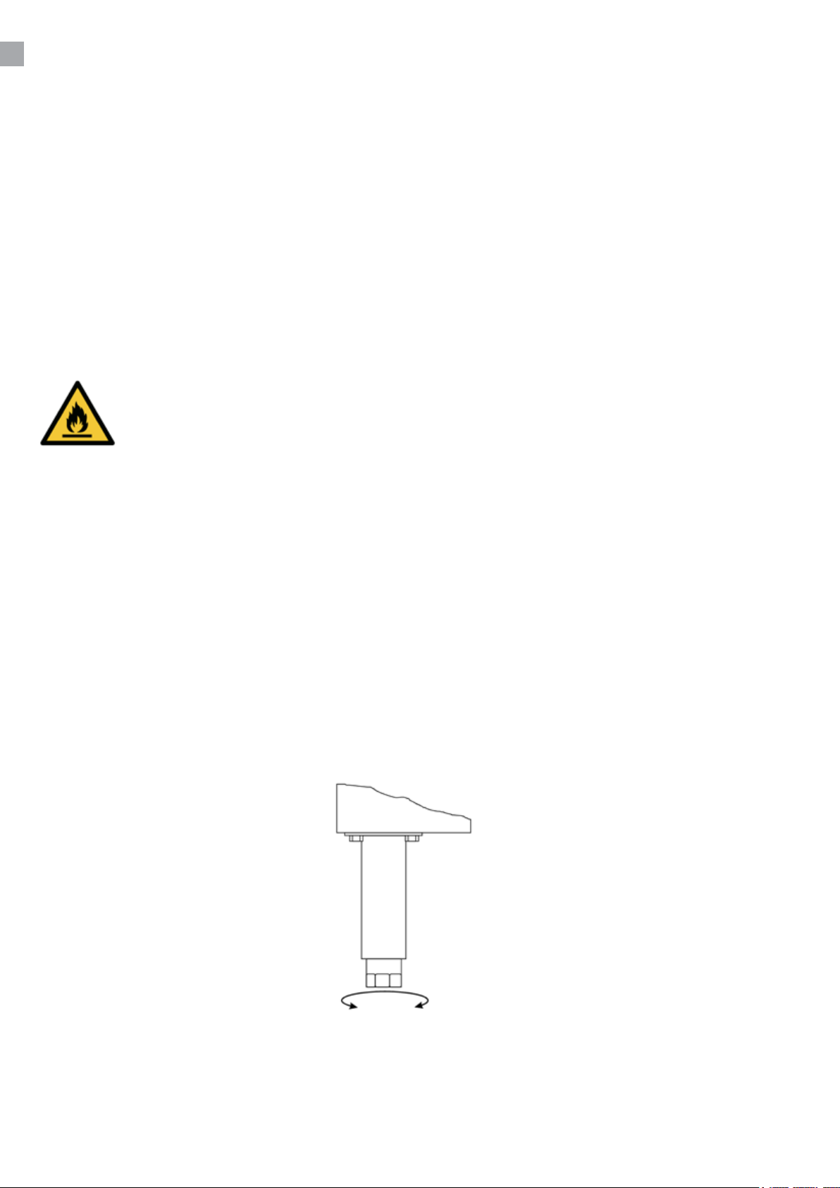
To ensure correct function it is important that the cabinet is level. If the cabinet is supplied with legs,
these can be adjusted.
Important !
1. Do not block the ventilation holes.
2. Make sure that there is at least 15 cm. free space between the cabinet and the wall.
4
Page 5

ELECTRICAL CONNECTION
BLC3, BLC5 and BLC10 cabinets operates on 230 V/50 Hz.
BLC14 operates on 3x400 V/50 Hz.
Make sure that the cabinet is connected to a separate electrical group to avoid overload.
The wall socket should be easily accessible.
All earthing requirements stipulated by the local electricity authorities must be observed. The cabinet
plug and wall socket should then give correct earthing. If in doubt, contact your local supplier or
authorized electrician.
The main electrical connections must be done by skilled electricians.
START-UP OF THE CABINET
Before use, we recommend that the cabinet is cleaned, see the section on maintenance and
cleaning.
Important !
If the cabinet has been horizontally placed during transport, please wait 2 hours before starting up
the cabinet.
CAPACITY
BLC3 BLAST CHILLER/FREEZER
Model suitable to contain 3 trays with blast chilling capacity of 12kg and 8 kg in shock freezing.
BLC5 BLAST CHILLER/FREEZER
Model suitable to contain 5 trays with blast chilling capacity of 18kg and 14kg in shock freezing.
BLC10 BLAST CHILLER/FREEZER
Model suitable to contain 10 trays with blast chilling capacity of 40kg and 28 kg in shock freezing.
BLC14 BLAST CHILLER/FREEZER
Model suitable to contain 14 trays with blast chilling capacity of 55kg and 38kg in shock freezing.
5
Page 6
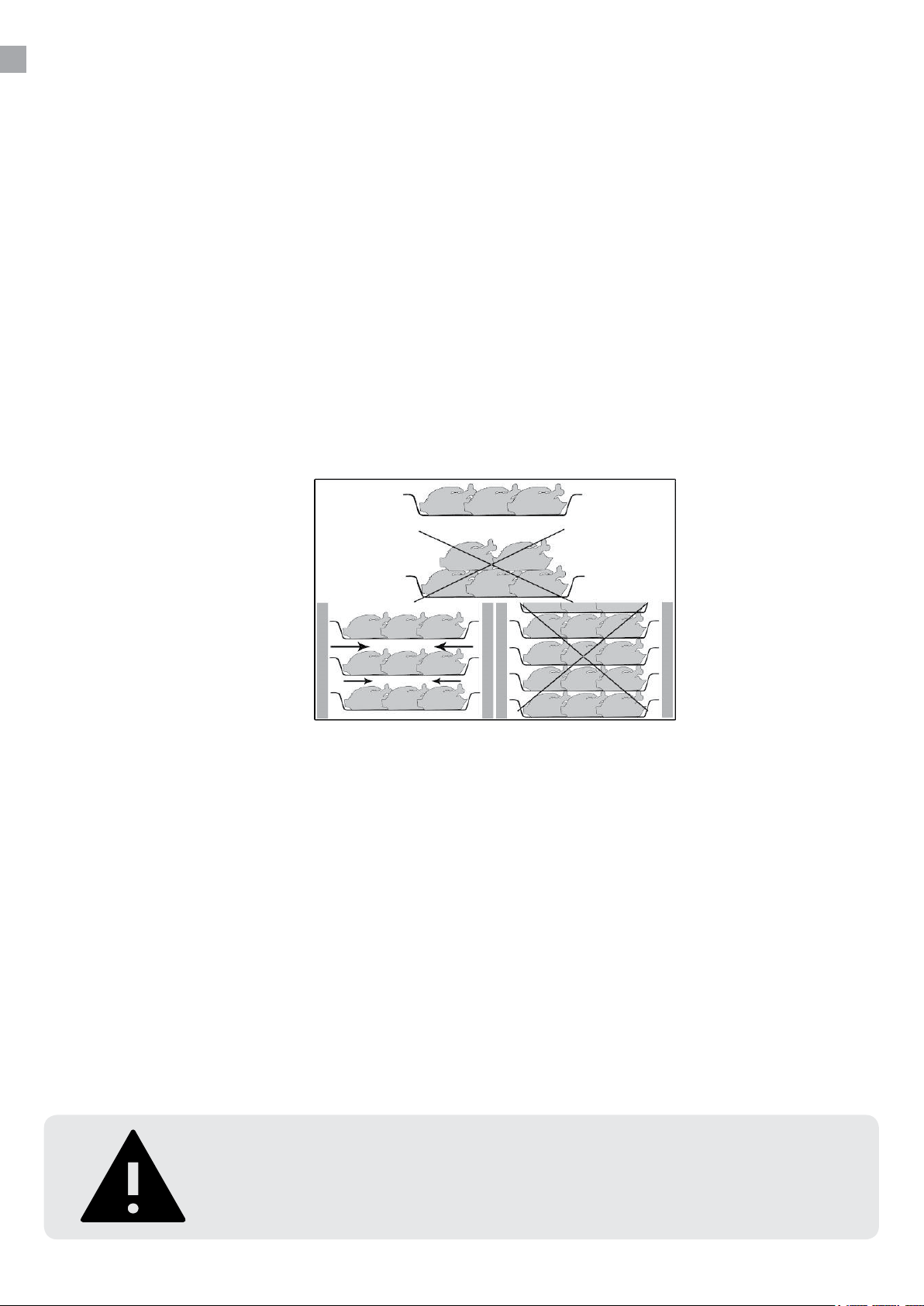
RECOMMENDATIONS FOR USE
If the appliance remains inactive for a long period, proceed as follows
1. Use the automatic isolating switch to deactivate connection to the main electrical line.
2. Clean the appliance and surrounding areas thoroughly.
3. Spread a thin layer of cooking oil onto the stainless steel surfaces
4. Carry out all maintenance operations
5. Leave the door ajar to prevent the formation of mould and / or unpleasant odour.
Do not insert foodstus that are above the temperature of 90 °C.
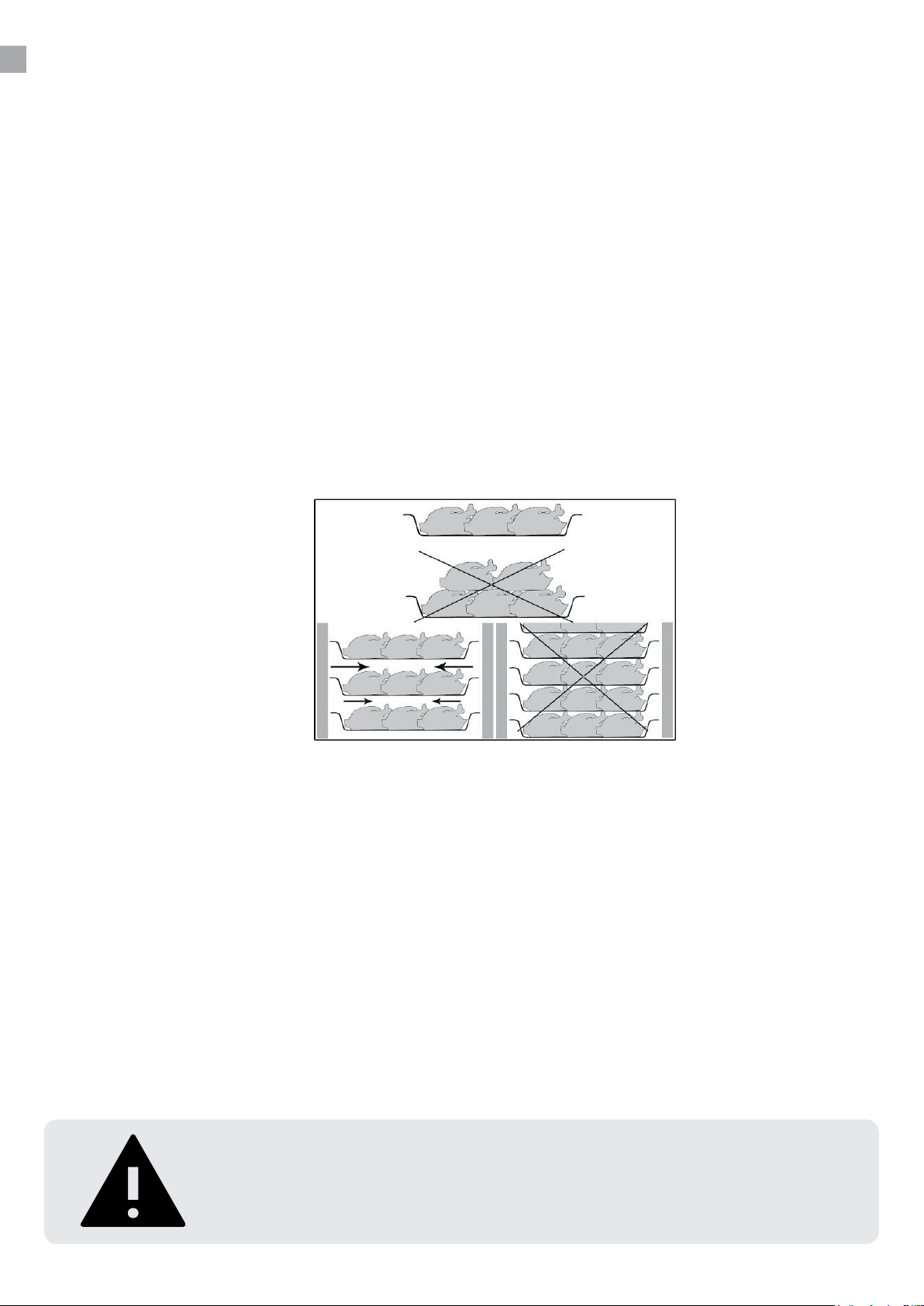
Do not stack the materials to be preserved in contact with the internal walls so blocking the circulation
of air.
There must be a sucient space between the trays used in order to guarantee a sucient ow of
cold air on the entire product.
Never obstruct the inlet of the evaporator fans.
Products that are more dicult to chill because of their size should be placed in the centre.
Limit the number of times and the duration of time the door are opened.
After blast chilling/shock freezing the product, it can be stored in a preservation cabinet after having
been duly protected .A tag should be applied describing the contents of the product, blast chilling/
shock freezing date and expiry date. When the product has been blast chilled it must be preserved at
a constant temperature of +2 °C while if it has been shock frozen it must be preserved at a constant
temperature of -20 °C.
The chiller should be used for storage for short periods only.
To prevent bacterial contamination or contamination of any other biological
nature, the needle probe must be disinfected after use.
6
Page 7

BLAST CHILLING CYCLE
With this operating modality the chiller keeps the temperature of the refrigerating compartment close
to zero during the entire chilling process in order to ensure a gradual drop in the temperature of the
product to +3 °C.In this way, ice crystals do not form on the surface of the product .This blast chilling
method should be used preferably for products that are not packed and whose physical/organoleptic
characteristics could be damaged by the formation of supercial ice (e.g. sh)
SHOCK FREEZING CYCLE
With this blast chilling modality the blast chiller maintains the temperature at a negative value below
-18 °C which is the end temperature of shock freezing .For shock freezing to be successful and fast,
food should be in small pieces, especially if it has a high fat content. The largest pieces should be
placed in central trays .If it takes longer than standard time to shock freeze and the sizes cannot
be reduced, decrease the quantity and precool the chiller compartment by starting an empty shock
freezing cycle before shock freezing the product.
CLEANING AND MAINTENANCE
Switch o the electrical connection at the socket.
The cabinet must be periodically cleaned. Clean the external and internal surfaces of the cabinet with
a light soap solution and subsequently wipe dry. External surfaces can be maintained using steel oil.
Do not spray the appliance with direct jets of water or using high pressure appliances.
Do not use iron wool. brushes or scrapers to clean the stainless steel as ferrous particles could be
deposited which ,on oxidizing, could lead to rust.
To remove hardened residues, use wooden or plastic spatulas or abrasive rubber pads.
Clean the condenser
Clean the condenser periodically.
As the ns of the condenser are very sharp, always wear protective gloves for the next phases.
Use protective masks and glasses in the presence of dust.
Whenever the condenser has a deposit of dust in correspondence with the ns, this can be
removed using a suction device or with a brush applied, using a vertical movement along the
direction of the ns.
No other instruments must be used, which may deform the ns and therefore the eciency of the
appliance.
7
Page 8

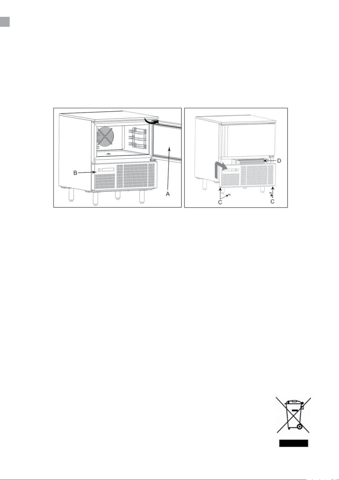
To clean, proceed as follows:
1. Open the door (A) of the appliances.
2. Remove the lower panel(B) from the technical compartment: to do this, remove the screw
fasteners(C)
3. It is now possible to clean the nned part of the condenser (D) using suitable tools and
protection devices.
4. After cleaning, close the control panel and x it with the screws removed beforehand.
SERVICE
The cooling system is a hermetically sealed system and does not require supervision, only cleaning.
If the cabinet fails to cool, check if the reason is a power cut.
If you cannot locate the reason to the failure of the cabinet, please contact your supplier. Please
inform model and serial number of the cabinet. You can nd this information on the rating label which
is placed inside the cabinet in the top right hand side.
DISPOSAL
Disposal of the cabinet must take place in an environmentally correct way. Please note existing
regulation on disposal. There may be special requirements and conditions which must be observed.
8
Page 9
QUICK GUIDE
For the daily use
9
Page 10
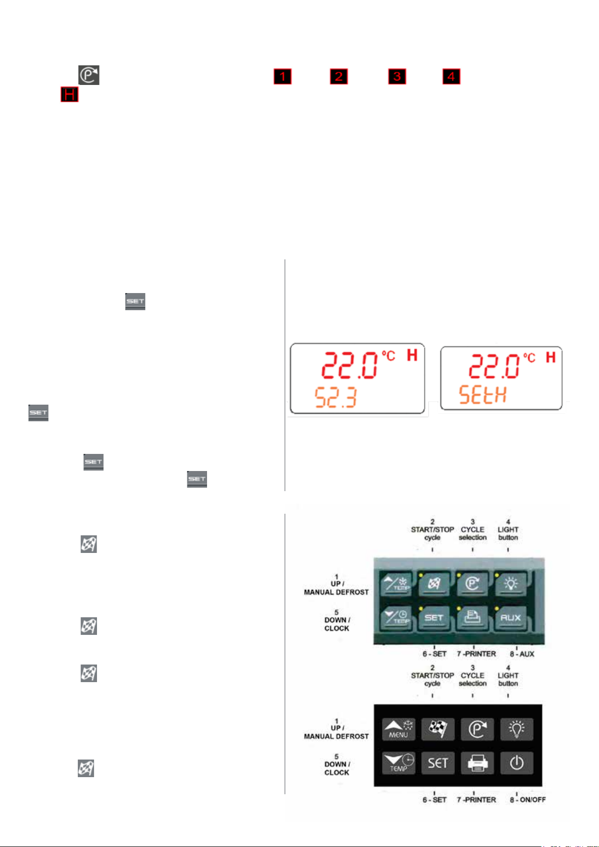
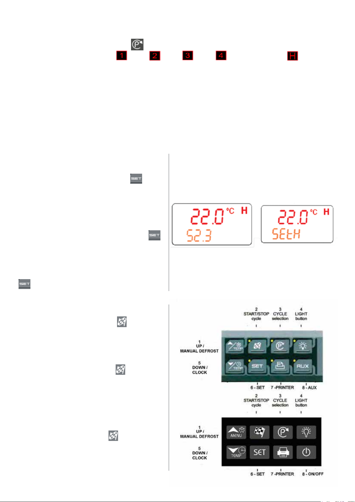
How to select a cycle
Push the to move among the cycles CY1 , CY2 , CY3 , CY4 and the holding
cycle .
The 5 programs have the default values shown in the diagrams next page.
CY1: Fast chilling and conservation. (Hard + soft chilling and holding)
1.
CY2: Chilling and fast freezing. (Hard + soft chilling, freezing and holding)
2.
CY3: Fast freezing. (Fast freezing and holding)
3.
CY4: Fast freezing with alarm and stop. (Only fast freezing)
4.
H: Hold mode function. (Hard chill or freezing)
5.
dEF: For starting a manual defrost.
6.
How to display the holding SET point.
While the Holding cycle is running (H-icon
lighted), push the key.
The Holding set point is displayed on the
upper display and the SETH labels is
displayed on the bottom display.
How to modify the holding SET point.
While the SETH is displayed, hold the
key pressed until the SETH label starts
ashing.
Use the arrow keys to modify the value and
press the key to conrm.
To conrm and exit, push the key again.
How to start a cycle.
Push the key and the selected cycle starts.
The yellow display is switched on.
Compressor is delayed by 3 min.
How to pause a cycle.
Push the key and the compressor and fan
will stop.
Stb will ash in the display during the pause.
Push the key to restart the cycle from the
point of interruption.
In any case the cycle automatically restarts
after the PAU time. (See manual)
How to stop a cycle.
Hold the key pressed untill the yellow
display switch o and the cycle is stopped.
10
Page 11

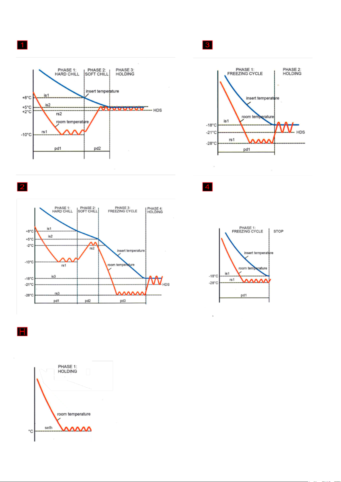
CY1: Hard chill + soft chill + holding
CY2: Hard chill + soft chill + freezing + holding CY4: Freezing cycle then stop
CY3: Freezing cycle + holding
H: Holding mode
11
Page 12

Blast Chillers
+70 °C to +3 °C
The blast chilling cycle reduce the product temperature from
+70 °C to +3 °C in 90 minuttes.
Bacterial generation is accelerating in the gap between +60 °C
and +10 °C, therefore it is essential to cool the product as fast
as possible.
Furthermore vitamins, taste and odour are preserved.
Should then be stored in normally chiller at +2 °C.
Blast Freezers
+70 °C to -18 °C
Bacterials destroyed
Bacterial acceleration
The blast freezing cycle reduce the product temperature from
+70 °C to -18 °C in 240 minuttes.
The fast reduction of the product temperature increases the
lifetime of the product.
Furthermore the quality is preserved without major loss of
weight, liquid and taste.
Should then be stored in normally freezer at -20 °C.
Bacterials in general
Chill Freeze
Bacterial reduction/
stop
rfj_191013
© TEFCOLD A/S 2019
Page 13
REFROIDISSEURS /
CONGÉLATEURS RAPIDES
Manuel d’utilisation
FR
IT
ES
PT
SL
13
25
37
49
61
Page 14

14
Page 15

SOMMAIRE
1.
2.
Informations générales
Consignes de sécurité importantes ..................................................................... 16
Déballage et installation ...................................................................................... 16
Raccordement électrique ..................................................................................... 17
Démarrage du congélateur .................................................................................. 17
Capacité .............................................................................................................. 17
Consignes d’utilisation ......................................................................................... 18
Cycle de refroidissement rapide .......................................................................... 19
Cycle de congélation rapide ................................................................................ 19
Nettoyage et maintenance ................................................................................... 19
Entretien .............................................................................................................. 20
Mise au rebut ....................................................................................................... 20
Guide rapide
3.
Guide rapide quotidien ........................................................................................ 21
Thermostat XB570L / XB590L
Manuel technique ................................................................................................ 73
15
Page 16

CONSIGNES DE SÉCURITÉ IMPORTANTES
1. Pour tirer le meilleur parti du congélateur, nous vous recommandons de lire de manuel d’utilisation.
2. L’utilisateur est responsable d’utiliser l’appareil conformément aux instructions données.
3. Contactez votre revendeur immédiatement en cas de dysfonctionnements.
4. Placez le congélateur dans un endroit sec et ventilé.
5. Conservez le congélateur à l’abri de sources de chaleur importante et ne l’exposez pas à la
lumière directe du soleil.
6. N’oubliez jamais que tous les appareils électriques sont des sources de danger potentiel.
7. Ne stockez pas de matériaux inammables tels que du diluant, de l’essence, etc. dans le
congélateur.
8. Nous déclarons n’avoir pas utilisé d’amiante ou de CFC lors de la construction.
9. L’huile dans le compresseur ne contient pas de PCB.
POUR LES ARMOIRES AVEC RÉFRIGÉRANT R290/R600a!
Ce refroissseur contient un réfrigérant inammable; assurez un endroit bien ventilé
autour de l’armoire. N’utilisez pas des outils mécaniques pour le dégivrage; cela peut
causer des fuites dans le système de refroidissement interne. N’utilisez pas des outils
électrique á l’intérieur de l’armoire.
Chaque réparation de ce réfroidisseur doit être eectué par un réparateur professionel.
(EN 60335-2-89: 2010)
DÉBALLAGE ET INSTALLATION
Retirez la palette en bois et l’emballage. Les surfaces externes sont recouvertes d’un lm de
protection que vous devez retirer avant l’installation.
Pour garantir un bon fonctionnement, il est important que le core soit horizontal. Si le core est doté
de pieds, vous pouvez les régler.
Important !
1. Ne bloquez pas les trous de ventilation.
2. Assurez-vous qu’il y a un espace d’au moins 15 cm entre le core et le mur.
16
Page 17

RACCORDEMENT ÉLECTRIQUE
Les cores BLC3-BLC5 et BLC10 fonctionnent avec 230 V/50 Hz.
Le BLC14 fonctionne avec 3x400 V/50 Hz.
Assurez-vous que le core est connecté à un groupe électrique distinct pour éviter les surcharges.
La prise murale doit être facile d’accès.
Toutes les exigences de mise à la terre stipulées par les autorités locales doivent être respectées. La
prise du congélateur et la prise murale doivent alors fournir la mise à la terre appropriée. En cas de
doute, contactez votre fournisseur local ou électricien autorisé.
Les principaux raccordements électriques doivent être eectués par un électricien professionnel.
DÉMARRAGE DU CONGÉLATEUR
Avant l’utilisation, nous vous recommandons de nettoyer le congélateur (voir la section sur la
maintenance et le nettoyage).
Important !
Si le congélateur a été placé horizontalement pendant le transport, attendez 2 heures avant de le
mettre en marche.
CAPACITÉ
REFROIDISSEURS/CONGÉLATEURS RAPIDES BLC3
Ce modèle peut contenir 3 plateaux avec une capacité de refroidissement rapide de 12 kg et de
congélation rapide de 8 kg.
REFROIDISSEURS/CONGÉLATEURS RAPIDES BLC5
Ce modèle peut contenir 5 plateaux avec une capacité de refroidissement rapide de 18kg et de
congélation rapide de 14kg.
REFROIDISSEURS/CONGÉLATEURS RAPIDES BLC10
Ce modèle peut contenir 10 plateaux avec une capacité de refroidissement rapide de 40kg et de
congélation rapide de 28 kg.
REFROIDISSEURS/CONGÉLATEURS RAPIDES BLC14
Ce modèle peut contenir 14 plateaux avec une capacité de refroidissement rapide de 55kg et de
congélation rapide de 38kg.
17
Page 18
CONSIGNES D’UTILISATION
Si l’appareil reste inactif pendant une période prolongée, procédez de la manière suivante
1. Utilisez le sectionneur automatique pour désactiver la connexion à l’alimentation électrique
principale.
2. Nettoyez bien l’appareil et les zones environnantes.
3. Étalez une ne couche d’huile de cuisine sur les surfaces en acier inoxydable
4. Réalisez toutes les opérations de maintenance
5. Laissez la porte entrebâillée pour empêcher la formation de moisissure et/ou les mauvaises
odeurs.
N’insérez pas d’aliments dont la température est supérieure à 90 °C.
N’empilez pas les éléments à préserver en contact avec les parois internes, ce qui risquerait de
bloquer la circulation de l’air.
Il doit y avoir un espace susant entre les plateaux utilisés an de garantir un débit susant d’air
froid sur tout le produit.
Ne bouchez jamais l’entrée des ventilateurs d’évaporateurs.
Les produits plus diciles à refroidir en raison de leur taille doivent être placés au centre.
Limitez le nombre et la durée d’ouverture de la porte.
Après un refroidissement/une congélation rapides du produit, vous pouvez le stocker dans un core
de préservation après l’avoir correctement protégé. Nous vous conseillons d’appliquer une étiquette
décrivant le contenu du produit, la date de refroidissement/congélation rapide et la date d’expiration.
Une fois le produit refroidi rapidement, préservez-le à une température constante de +2°C alors que
s’il il a été congelé rapidement, préservez-le à une température constante de -20°C. Le refroidisseur
doit être utilisé pour un stockage de courte durée uniquement.
Pour empêcher la contamination bactérienne ou toute autre contamination
de nature biologique, la sonde à aiguille doit être désinfectée après
utilisation.
18
Page 19

CYCLE DE REFROIDISSEMENT RAPIDE
Avec ce mode de fonctionnement, le refroidisseur maintient la température du compartiment de
réfrigération proche de zéro pendant tout le processus de refroidissement an de garantir une baisse
progressive de la température du produit jusqu’à +3°C. Ainsi, aucun cristal de glace ne se forme à
la surface du produit. Cette méthode de refroidissement rapide doit être utilisée de préférence pour
les produits non emballés et dont les caractéristiques physiques/organoleptiques pourraient être
aectées par la formation de glace supercielle (par ex. le poisson)
CYCLE DE CONGÉLATION RAPIDE
Avec ce mode de refroidissement rapide, le refroidisseur rapide maintient la température à une
valeur négative inférieure à -18°C ce qui correspond à la température nale de la congélation rapide.
Pour que la congélation rapide soit réussie et rapide, les aliments doivent être en petits morceaux,
en particulier si sa teneur en graisse est élevée. Les plus gros morceaux doivent être placés sur
les plateaux centraux. S’il faut plus de temps que le temps habituel pour la congélation rapide et
que la taille des morceaux ne peut être réduite, réduisez la quantité et refroidissez préalablement
le compartiment du refroidisseur en démarrant un cycle de congélation rapide à vide avant la
congélation rapide du produit.
NETTOYAGE ET MAINTENANCE
Coupez le raccordement électrique au niveau de la prise.
Le congélateur doit être nettoyé régulièrement. Nettoyez les surfaces externes et internes du
congélateur à l’aide d’une solution savonneuse douce puis séchez. Les surfaces externes peuvent
être entretenues à l’aide d’huile pour l’acier.
Ne pulvérisez pas l’appareil avec des jets d’eau directs ou à l’aide d’appareils haute pression.
N’utilisez pas de laine de fer, de brosses ou de racloirs pour nettoyer l’acier étant donné que des
particules ferreuses risquent de se déposer et, lors de leur oxydation, de former de la rouille.
Pour éliminer les résidus secs, utilisez des spatules en bois ou en plastique ou des tampons abrasifs
en caoutchouc.
Nettoyage du condensateur
Nettoyez le condensateur régulièrement
Comme les ailettes du condensateur sont très tranchantes, portez toujours des gants de protection
pour réaliser les étapes suivantes. Utilisez des masques et des lunettes de protection s’il y a de la
poussière
Lorsque le condensateur présente un dépôt de poussière correspondant aux ailettes, vous pouvez
l’éliminer à l’aide d’un appareil d’aspiration ou avec une brosse, en exerçant un mouvement vertical
dans le sens des ailettes.
N’utilisez aucun autre instrument susceptible de déformer les ailettes et, par conséquent, d’aecter
l’ecacité de l’appareil.
19
Page 20
Pour le nettoyage, procédez comme suit :
1. Ouvrez la porte (A) des appareils.
2. Retirez le panneau inférieur (B) du compartiment technique : pour cela, retirez les vis (C)
3. Vous pouvez maintenant nettoyer les ailettes du condensateur (D) à l’aide des outils et des
dispositifs de protection adaptés.
4. Une fois le nettoyage terminé, fermez le panneau de commande et xez-le à l’aide des vis que
vous avez retirées.
ENTRETIEN
Le système de refroidissement est un système fermé hermétiquement qui ne nécessite pas d’être
surveillé, mais uniquement d’être nettoyé.
Si le congélateur ne refroidit pas, vériez si la raison est une panne de courant.
Si vous ne pouvez pas détecter la raison de la défaillance du congélateur, veuillez contacter votre
fournisseur. Veuillez indiquer le modèle et le numéro de série du congélateur. Vous pourrez trouver
ces informations sur l’étiquette de cote énergétique placée à l’intérieur du congélateur en haut à
droite.
MISE AU REBUT
La mise au rebut du congélateur doit être eectuée dans le respect de l’environnement. Veuillez
consulter la réglementation existante sur la mise au rebut. Il peut y avoir des exigences et conditions
spéciales à respecter.
20
Page 21

GUIDE RAPIDE
Guide rapide quotidien
21
Page 22
SÉLECTIONNER UN CYCLE
Appuyer en séquence sur la touche pour sélectionner un cycle, lors de chaque pression
l’écran ache la sélection CY1 , CY2 , CY3 , CY4 , cycle de maintien .
Les 5 programmes ont les valeurs par défaut montrées dans les diagrammes page suivante.
CY1: Refroidissement rapide et début de la phase de conservation.
1.
CY2: Refroidissement rapide, surgélation rapide et début de la phase de conservation.
2.
CY3: Surgélation rapide et début de la phase de conservation.
3.
CY4: Congélation rapide avec alarme et arrêt.
4.
H: Fin du cycle de congélation et début de la phase de conservation (sélectionnable).
5.
dEF: S’assurer qu’aucun cycle ne soit actif ou que la conservation est en cours.
6.
Acheur les valeurs réglage.
Lorsqu’un maintien est sélectionné, l’icône H
allumée, en appuyant sur la touche
La valeur suivante est achée:
SETH = valeur du thermostat de la cellule en
phase de maintien.
Modication.
Avant 5 secondes, appuyer sur la touche
pendant 2 secondes, et l’inscription achée
clignotent.
Modier la valeur avec les touches èche.
Conrmer et quitter : appuyer à nouveau sur
Démarrer un cycle.
Appuyer et relâcher le bouton .
La LED jaune correspondante s’allume.
Le compresseur est retardé de 3 min.
Arrêt manuel.
Appuyer et relâcher le bouton .
la LED jaune clignote.
Le redémarrage s’eectue en appuyant sur la
touche ou automatiquement après la durée de
pause PAU.
Arrêt dénitif.
Maintenir appuyé le bouton .
La LED jaune s’éteint.
22
Page 23
CY1: Refroidissement rapide
et début de la phase de conservation
CY3: Surgélation rapide et début
de la phase de conservation
CY2: Refroidissement rapide, surgélation rapide
et début de la phase de conservation
H: Fin du cycle de congélation et début de la
phase de conservation
CY4: Congélation rapide avec
alarme et arrêt
23
Page 24
Refroidisseurs rapides
+70 °C to +3 °C
Le cycle de refroidissement rapide réduit la température du
produit de +70 °C à +3 °C en 90 minutes.
La génération bactérienne s’accélère dans l’intervalle entre
+60 °C et +10 °C ; il est donc essentiel de refroidir le produit le
plus rapidement possible.
De cette manière, les vitamines, le goût et l’odeur sont
préservés.
Après, il faut stocker les produits alimentaires dans un
refroidisseur normal à +2 °C.
Congélateurs rapides
+70 °C to -18 °C
Bactéries détruites
Accélération bactérienne
Le cycle de congélation rapide réduit la température du produit
de +70 °C à -18 °C en 240 minutes.
La réduction rapide de la température du produit augmente la
durée de vie du produit. De plus, la qualité est préservée sans
perte importante de poids, de liquide ou de goût.
Après, il faut stocker les produits alimentaires dans un
congélateur normal à -20 °C.
Bactéries en général
Refroidissement Congélateur
Réduction / arrêt bactérien
rfj_191013
© TEFCOLD A/S 2019
Page 25
ABBATTITORI/CONGELATORI
Manuale d’uso
IT
ES
PT
SL
25
37
49
61
Page 26

26
Page 27

SOMMARIO
1.
2.
Informazioni generali
Istruzioni di sicurezza .......................................................................................... 28
Disimballaggio e installazione ............................................................................. 28
Collegamenti elettrici ........................................................................................... 29
Avviamento .......................................................................................................... 29
Capacità .............................................................................................................. 29
Raccomandazioni per l’uso ................................................................................. 30
Ciclo di abbattimento ........................................................................................... 31
Ciclo di congelamento rapido .............................................................................. 31
Pulizia e manutenzione ....................................................................................... 31
Servizio assistenza .............................................................................................. 32
Smaltimento ......................................................................................................... 32
Guida rapida
3.
Guida pratica quotidiana ...................................................................................... 33
Termostato XB570L / XB590L
Libretto di istruzioni .............................................................................................. 73
27
Page 28
ISTRUZIONI DI SICUREZZA
1. Per un corretto funzionamento dell’armadio frigo consigliamo di leggere attentamente questo
manuale di istruzioni.
2. È responsabilità dell’utente utilizzare il dispositivo in conformità alle istruzioni date.
3. In caso di guasto contattare immediatamente il proprio rivenditore.
4. Posizionare l’armadio in un luogo asciutto e ventilato.
5. Tenere l’armadio frigo lontano da fonti di calore intenso e non esporlo direttamente alla luce del
sole.
6. Ricordare sempre che tutti i dispositivi elettrici sono potenziali fonti di pericolo.
7. Non conservare materiale inammabile come solventi, benzina, ecc. all’interno dell’armadio.
8. Si dichiara che durante la costruzione non sono stati utilizzati CFC o amianto.
9. L’olio nel compressore non contiene PCB.
SOLO PER APPARECCHI CON REFRIGERANTE R290/R600a!
Questo apparecchio contiene un refrigerante inammabile: assicurarsi che vi sia una
buona ventilazione intorno all’apparecchio. Non utilizzare dispositivi meccanici in fase
di scongelamento per evitare perdite del sistema di rareddamento. Non utilizzare
dispositivi elettrici all’interno del vano di conservazione refrigerato.
Qualsiasi riparazione dell’apparecchio deve essere svolta da un tecnico qualicato
(EN 60335-2-89: 2010).
DISIMBALLAGGIO E INSTALLAZIONE
Rimuovere il pallet in legno e l’imballaggio. Le superci esterne sono ricoperte da una pellicola di
protezione che deve essere rimossa prima dell’installazione.
Per garantire il corretto funzionamento è importante che l’armadio frigo si trovi in piano. L’armadio
frigo è dotato di piedini regolabili.
Importante !
1. Non ostruire i fori di ventilazione.
2. Vericare che tra l’armadio frigo e il muro vi sia uno spazio libero di almeno 15 cm.
28
Page 29

COLLEGAMENTI ELETTRICI
Gli armadi BLC3, BLC5 e BLC10 funzionano a 230 V/50 Hz.
L’armadio BLC14 funziona a 3x400 V/50 Hz.
Per evitare il sovraccarico, accertarsi che l’armadio sia collegato a un gruppo elettrico separato.
La presa a muro deve essere facilmente accessibile.
È necessario osservare tutti i requisiti di messa a terra previsti dall’ente locale per l’energia elettrica.
La spina e la presa a muro dell’armadio dovrebbero essere correttamente collegate a terra. In caso di
dubbi contattare il fornitore locale o un elettricista autorizzato.
I collegamenti elettrici principali devono essere eseguiti da elettricisti qualicati.
AVVIAMENTO
Prima dell’uso controllare che l’armadio sia pulito; consultare in merito la sezione relativa a
manutenzione e pulizia.
Importante !
Se l’armadio frigo è stato trasportato in posizione orizzontale attendere 2 ore prima dell’attivazione.
CAPACITÀ
ABBATTITORE/CONGELATORE BLC3
Il modello può contenere 3 vassoi con una capacità di abbattimento di 12 kg e 8 kg in caso di
congelamento rapido.
ABBATTITORE/CONGELATORE BLC5
Il modello può contenere 5 vassoi con una capacità di abbattimento di 18 kg e 14 kg in caso di
congelamento rapido.
ABBATTITORE/CONGELATORE BLC10
Il modello può contenere 10 vassoi con una capacità di abbattimento di 40 kg e 28 kg in caso di
congelamento rapido.
ABBATTITORE/CONGELATORE BLC14
Il modello può contenere 14 vassoi con una capacità di abbattimento di 55 kg e 38 kg in caso di
congelamento rapido.
29
Page 30

RACCOMANDAZIONI PER L’USO
Se l’apparecchio rimane inattivo per un periodo di tempo prolungato, procedere come segue.
1. Usare l’interruttore automatico di isolamento per disattivare il collegamento con la linea elettrica.
2. Pulire accuratamente l’apparecchio e le zone circostanti.
3. Applicare un sottile strato di olio da cucina sulle superci in acciaio inossidabile.
4. Eseguire tutte le operazioni di manutenzione.
5. Lasciare lo sportello socchiuso per prevenire la formazione di mua e/o odori sgradevoli.
Non riporre nell’armadio alimenti con una temperatura superiore a 90 °C.
Non appoggiare gli alimenti da conservare a contatto con le pareti interne bloccando così la
circolazione dell’aria.
Accertarsi che la distanza tra i vassoi sia tale da garantire un suciente usso di aria fredda su tutto
il prodotto.
Non ostruire l’ingresso delle ventole dell’evaporatore.
I prodotti più dicili da refrigerare per dimensioni devono essere posizionati al centro.
Limitare il numero di volte e la durata del tempo di apertura degli sportelli.
Una volta sottoposto ad abbattimento di temperatura/congelamento rapido, il prodotto può essere
conservato un armadio di conservazione. A tale scopo, esso dovrà essere debitamente protetto e
munito di etichetta indicante il contenuto, la data di abbattimento/congelamento rapido e la data di
scadenza. Dopo l’abbattimento di temperatura, il prodotto deve essere conservato a una temperatura
costante di +2°C in caso di congelamento rapido il prodotto dovrà essere conservato a una
temperatura costante di -20°C.
L’abbattitore deve essere utilizzato per la conservazione solo per brevi periodi.
Per evitare contaminazioni di natura batterica o altra natura biologica,
sterilizzare la sonda ad ago dopo l’uso.
30
Page 31

CICLO DI ABBATTIMENTO
In questa modalità operativa, l’abbattitore mantiene la temperatura dello scomparto di refrigerazione
prossima allo zero durante l’intero processo di abbattimento, assicurando così una diminuzione
graduale della temperatura del prodotto no a +3°C. In questo modo, si evita la formazione di cristalli
di ghiaccio sulla supercie del prodotto. Questo metodo di abbattimento della temperatura è da
preferirsi nel caso di prodotti non confezionati e le cui caratteristiche sico-organolettiche potrebbero
risultare compromesse dalla formazione di ghiaccio superciale (ad es. pesce)
CICLO DI CONGELAMENTO RAPIDO
In questa modalità operativa, l’abbattitore mantiene la temperatura a un valore negativo inferiore
a -18°C ovvero la temperatura nale per il congelamento rapido. Per eettuare un congelamento
rapido in maniera rapida ed ecace, il cibo deve essere inserito in piccole pezzature, specialmente
se ha un contenuto di grassi elevato. Posizionare i pezzi di dimensioni maggiori nei vassoi centrali.
Se il congelamento rapido richiede più tempo della norma e non è possibile ridurre la pezzatura
del cibo, diminuire la quantità e prerareddare lo scomparto di abbattimento avviando un ciclo di
congelamento rapido a vuoto prima di eettuare quello con il prodotto.
PULIZIA E MANUTENZIONE
Scollegare l’apparecchio dalla presa.
Il dispositivo deve essere pulito periodicamente. Pulire le superci interne ed esterne dell’armadio
con una soluzione detergente delicata e asciugare. È possibile eseguire una manutenzione delle
superci esterne in acciaio utilizzando appositi oli.
Non utilizzare getti diretti di acqua sull’apparecchio né pulitori ad alta pressione.
Non usare lana metallica né spazzole o raschiatori in ferro per pulire le parti in acciaio inossidabile
poiché le particelle ferrose che si depositano potrebbero, ossidando, causare la formazione di
ruggine.
Per rimuovere residui incrostati, usare una spatola di legno o plastica oppure una spugna in gomma
abrasiva.
Pulizia del condensatore
Pulire il condensatore periodicamente
Essendo le alette del condensatore molto alate, durante le fasi seguenti indossare sempre guanti
protettivi. In presenza di polvere, usare maschere e occhiali protettivi.
Qualora il condensatore presenti depositi di polvere in corrispondenza delle alette, rimuoverli
utilizzando un dispositivo di aspirazione o una spazzola compiendo un movimento verticale lungo
la direzione delle alette stesse.
Non utilizzare nessun altro strumento che potrebbe deformare le alette e compromettere
l’ecienza dell’apparecchio.
31
Page 32

Per la pulizia procedere come segue:
1. Aprire lo sportello (A) dell’apparecchio.
2. Rimuovere il pannello inferiore (B) dallo scomparto tecnico, a tale scopo rimuovere i le viti di
ssaggio (C).
3. Servendosi di idonei strumenti e dispositivi di protezione, è ora è possibile pulire la parte alettata
del condensatore (D).
4. Terminate le operazioni di pulizia, chiudere il quadro di comando e ssarlo con le viti
precedentemente rimosse.
SERVIZIO ASSISTENZA
Il sistema di rareddamento è un sistema chiuso ermeticamente e non richiede supervisione, è
suciente la pulizia.
Se l’armadio frigo non si raredda, controllare che non si tratti di un’interruzione di corrente.
Se non è possibile stabilire la causa del guasto, contattare il fornitore. Indicare il modello e il numero
di serie del dispositivo. Queste informazioni sono riportate sulla targhetta che si trova all’interno
dell’armadio frigo, in alto a destra.
SMALTIMENTO
L’armadio frigo deve essere smaltito in modo ambientalmente corretto. Attenersi ai regolamenti sullo
smaltimento esistenti. Potrebbero esserci condizioni e requisiti speciali da osservare.
32
Page 33

GUIDA RAPIDA
Guida pratica quotidiana
3333
Page 34

SELEZIONARE UN CICLO
Premere in sequenza il tasto per selezionare un ciclo, ad ogni pressione il display visualizza
la selezion CY1 , CY2 , CY3 , CY4 , ciclo di mantenimento .
I programmi di 5 hanno i valori di default indicati nei diagrammi pagina seguente.
CY1: Ciclo di abbattimento e conservazione a temp. positiva.
1.
CY2: Ciclo di abbattimento e surgelamento con conservazione.
2.
CY3: Ciclo di surgelamento rapido e conservazione.
3.
CY4: Ciclo di surgelamento rapido senza conservazione.
4.
H: Ciclo di mantenimento
5.
dEF: Inoltrata una richiesta di sbrinamento.
6.
Visualizzare i set de regolazione.
Quando è selezionato un mantenimento, icona
H accesa, premendo il tasto si visualizza:
- SEtH = set termostato cella in mantenimento.
Modica.
Entro 5 secondi premere il tasto set per 2
secondi, lampeggia il led del tasto e la
scritta a display.
Modicare il valore con i tasti freccia.
Conferma e uscita, premere ancora .
Avviare un ciclo.
Premere e rilasciare il pulsante .
Il corrispondente led giallo si illumina.
Compressore è ritardato di 3 minuti.
Fermata manuale.
Premere e rilasciare il pulsante , il led
giallo lampeggia. La ripartenza viene data
ripremendo il tasto o in automatico dopo il
tempo PAU.
Fermata denitiva.
Tenere premuto il pulsante , il led giallo si
spegne.
34
Page 35

CY1: Abbattimento + rareddamento controllato
+ conservazione
CY3: Surgelamento rapido +
conservazione
CY2: Abbattimento + rareddamento controllato
+ surgelamento rapido + conservazione
H: Ciclo di mantenimento
CY4: Surgelamento rapido senza
conservazione
35
Page 36

Abbattitori
+70 °C to +3 °C
Il ciclo di abbattimento a ridurre la temperatura del prodotto da
+70 °C al +3 °C a 90 minuti.
Generazione batterica sta accelerando nello spazio tra +60 °C
e +10 °C, quindi è indispensabile per rareddare il prodotto il
più velocemente possibile.
Inoltre le vitamine, il gusto e l’odore
Dovrebbe poi essere conservati in refrigeratore normalmente a + 2 °C.
Congelatori
+70 °C to -18 °C
Bacterials distrutti
Accelerazione batterica
Il ciclo di surgelazione a ridurre la temperatura del prodotto da
+70 °C a -18 °C a 240 minuti.
La rapida riduzione della temperatura del prodotto aumenta la
durata del prodotto.
Inoltre, la qualità viene conservato senza grave perdita di peso,
liquidi e gusto.
Dovrebbe poi essere conservato in congelatore normalmente a -20 °C.
Bacterials in generale
Abbattitori Congelatori
Riduzione batterica/stop
rfj_191013
© TEFCOLD A/S 2019
Page 37

ABATIDORES/CONGELADORES
Manual del usuario
ES 37
PT
SL
49
61
Page 38

38
Page 39

CONTENIDO
1.
2.
Información general
Instrucciones de seguridad importantes .............................................................. 40
Desembalaje e instalación ................................................................................... 40
Conexión eléctrica ............................................................................................... 41
Puesta en marcha de la unidad ........................................................................... 41
Capacidad ........................................................................................................... 41
Recomendaciones de uso ................................................................................... 42
Ciclo de abatimiento ............................................................................................ 43
Ciclo de congelación de choque .......................................................................... 43
Limpieza y mantenimiento ................................................................................... 43
En caso de avería ................................................................................................ 44
Eliminación .......................................................................................................... 44
Guía rápida
3.
Guía rápida diaria ................................................................................................. 45
Termostato XB570L / XB590L
Manual técnico ..................................................................................................... 73
39
Page 40

INSTRUCCIONES DE SEGURIDAD
IMPORTANTES
1. Para obtener el máximo rendimiento del armario, recomendamos la lectura de este manual de
instrucciones.
2. Es responsabilidad del usuario utilizar el electrodoméstico de acuerdo con las instrucciones
facilitadas.
3. Póngase en contacto inmediatamente con su concesionario en caso de cualquier anomalía.
4. Coloque el armario en un lugar seco y ventilado.
5. Mantenga el armario alejado de fuentes de mucho calor y no lo exponga a la luz solar directa.
6. Tenga siempre en cuenta que todos los dispositivos eléctricos pueden ser el origen de peligros
potenciales.
7. No almacene materiales inamables como disolvente, gasolina, etc., en el armario.
8. Declaramos que no se ha usado amianto ni CFC en su construcción.
9. El aceite del compresor no contiene PCB.
¡SOLO PARA LOS MODELOS QUE INCORPOREN REFRIGERANTE R290/R600a!
Este electrodoméstico contiene un refrigerante inamable. Por lo tanto, asegúrese de
disponer de una buena ventilación a su alrededor. No utilice dispositivos mecánicos
para descongelar el electrodoméstico, ya que podría causar fugas en el sistema
de refrigeración.No utilice aparatos eléctricos en el interior del compartimento de
almacenamiento refrigerado.
Deje cualquier reparación del electrodoméstico en manos de un técnico cualicado
(EN 60335-2-89: 2010).
DESEMBALAJE E INSTALACIÓN
Retire el palet de madera y el embalaje. Las supercies exteriores llevan una lámina de protección
que se debe retirar antes de la instalación.
Para asegurar un correcto funcionamiento es importante que el armario esté nivelado. Si el armario
se suministra con patas, se pueden ajustar.
¡Importante!
1. No bloquee los oricios de ventilación.
2. Asegúrese de dejar al menos 15 cm de espacio libre entre el armario y la pared.
40
Page 41

CONEXIÓN ELÉCTRICA
Los armarios BLC3-BLC5 y BLC10 funcionan con 230 V/50 Hz.
BLC14 funciona con 3x400 V/50 Hz.
Asegúrese de que el armario esté conectado a un grupo eléctrico aparte para evitar sobrecargas.
La toma eléctrica de la pared debe ser fácilmente accesible.
Se deben cumplir todos los requisitos de conexión a tierra estipulados por las empresas de
suministro eléctrico de su país. El enchufe del armario y la toma de la pared deben tener una
conexión a tierra correcta. En caso de duda, póngase en contacto con su proveedor local o un
electricista homologado.
Las conexiones eléctricas del suministro principal las deben efectuar electricistas con experiencia.
PUESTA EN MARCHA DE LA UNIDAD
Antes del uso, recomendamos limpiar el armario; remítase a la sección sobre mantenimiento y
limpieza.
¡Importante!
Si el armario se ha colocado horizontalmente durante el transporte, espere 2 horas antes de
ponerlo en marcha.
CAPACIDAD
ABATIDOR / CONGELADOR BLC3
Modelo adecuado para contener 3 bandejas con capacidad de abatimiento de 12 kg y 8 kg en
congelación de choque.
ABATIDOR / CONGELADOR BLC5
Modelo adecuado para contener 5 bandejas con capacidad de abatimiento de 18kg y 14kg en
congelación de choque.
ABATIDOR / CONGELADOR BLC10
Modelo adecuado para contener 10 bandejas con capacidad de abatimiento de 40kg y 28 kg en
congelación de choque.
ABATIDOR / CONGELADOR BLC14
Modelo adecuado para contener 14 bandejas con capacidad de abatimiento de 55kg y 38kg en
congelación de choque.
41
Page 42

RECOMENDACIONES DE USO
Si el equipo va a estar inactivo durante mucho tiempo, proceda del siguiente modo
1. Use el seccionador para desactivar la conexión con la red eléctrica.
2. Limpie a fondo el equipo y el área circundante.
3. Aplique una na capa de aceite de cocina sobre las supercies de acero inoxidable.
4. Realice todas las operaciones de mantenimiento
5. Deje la puerta entreabierta para evitar la formación de moho y/o de olores desagradables.
No introduzca alimentos a temperaturas por encima de 90 °C.
No apile los materiales que desea conservar en contacto con las paredes internas de forma que
bloqueen la circulación de aire.
Debe haber suciente espacio entre las bandejas, a n de garantizar un ujo suciente de aire frío
por todo el producto.
Nunca obstruya la entrada de los ventiladores de evaporación.
Los productos más difíciles de enfriar por su tamaño se deben colocar en el centro.
Limite el número de veces y el tiempo de apertura de la puerta.
Después de abatir/congelar el producto, se puede guardar en un armario de conservación una
vez protegido debidamente. Es conveniente colocar una etiqueta que describa el contenido del
producto, la fecha de abatimiento/congelación y la de caducidad. Si el producto se ha abatido, debe
conservarse a una temperatura constante de +2 °C, mientras que, si se ha congelado por choque,
debe conservarse a una temperatura constante de -20 °C.
El abatidor solo se debe usar para periodos cortos de conservación.
Para evitar la contaminación bacteriana o biológica de otro tipo, la sonda
de aguja se debe desinfectar después de cada uso.
42
Page 43

CICLO DE ABATIMIENTO
Con esta modalidad de funcionamiento, el abatidor mantienen la temperatura del compartimento
refrigerador cerca de cero durante todo el proceso de abatimiento para garantizar un descenso
gradual de la temperatura del producto hasta +3 °C.De este modo, no se forman cristales de
hielo en la supercie del producto. El método de abatimiento se debe usar, preferentemente, para
productos no envasados y cuyas características físicas/organolépticas pueden degradarse debido a
la formación de hielo supercial (p. ej., pescado)
CICLO DE CONGELACIÓN DE CHOQUE
Con esta modalidad de abatimiento, el abatidor mantiene la temperatura en un valor negativo
inferior a -18 °C que es la temperatura nal de la congelación de choque. Para que la congelación
de choque se produzca rápidamente y con éxito, la comida debe estar en piezas pequeñas,
especialmente si tiene un alto contenido en grasa. Las piezas más grandes se deben situar en las
bandejas centrales. Si la congelación de choque tarda más tiempo del estándar y no se pueden
reducir los tamaños, reduzca la cantidad y enfríe previamente el compartimento del abatidor
iniciando un ciclo de congelación de choque antes de congelar el producto.
LIMPIEZA Y MANTENIMIENTO
Desenchufe el equipo por la toma de corriente.
El armario se debe limpiar periódicamente. Limpie las supercies externas e internas del armario con
una solución jabonosa ligera y séquelas después con un trapo. Las supercies externas se pueden
mantener usando aceite de máquina.
No pulverice agua directamente sobre el aparato ni use aparatos de alta presión.
No use lana de acero, cepillos ni rascadores para limpiar el acero inoxidable, porque podrían
depositarse partículas ferrosas que podrían oxidarse.
Para eliminar los residuos persistentes, use espátulas de madera o plástico o esponjas de goma
abrasivas.
Limpie el condensador
Limpie el condensador periódicamente
Las láminas del condensador están muy aladas: lleve siempre guantes protectores para las
siguientes fases. Use máscara y gafas protectoras en presencia de polvo.
Siempre que el condensador tenga un depósito de polvo en la zona de las láminas, puede
eliminarlo usando un dispositivo aspirador o un cepillo aplicado en movimientos verticales a lo
largo de la dirección de las aletas.
No use ningún otro instrumento porque podría deformar las láminas y, por tanto, afectar a la
eciencia del equipo.
43
Page 44

Para limpiar, proceda como sigue:
1. Abra la puerta (A) del equipo.
2. Retire el panel inferior (B) del compartimento técnico: para ello, quite los tornillos de sujeción (C)
3. Ahora puede limpiar la parte laminada del condensador (D) usando herramientas y dispositivos
de protección adecuados.
4. Después de limpiar, cierre el panel de control y fíjelo con los tornillos que retiró previamente.
EN CASO DE AVERÍA
El sistema de refrigeración es un sistema sellado herméticamente que no requiere supervisión, solo
limpieza.
Si el armario no enfría, compruebe si el motivo es un corte de suministro eléctrico.
Si no puede encontrar el motivo de la avería del armario, póngase en contacto con su proveedor.
Indique el modelo y el número de serie del armario. Puede encontrar dicha información en la etiqueta
de características situada en el interior del armario, en el lado superior derecho.
ELIMINACIÓN
El armario se debe eliminar de forma respetuosa con el medio ambiente. Tenga en cuenta la
normativa existente en cuanto a residuos. Es posible que haya requisitos y condiciones especiales
que deban cumplirse.
44
Page 45

GUÍA RÁPIDA
Guía rápida diaria
45
Page 46

SELECCIONAR UN CICLO
Pulse la tecla para seleccionar el ciclo deseado CY1 , CY2 , CY3 , CY4 ,
ciclo de mantenimiento .
Los 5 programas tienen los valores por defecto mostrados en los diagramas de la página
siguiente.
CY1: Enfriamiento rápido y conservación a temp. positiva.
1.
CY2: Enfriamiento rápido y congelación con conservación.
2.
CY3: Congelación rápida y conservación.
3.
CY4: Congelación rápida sin conservación.
4.
H: El ciclo de mantenimiento.
5.
dEF: Activará una descongelación.
6.
Ver la temperatura de mantenimiento.
Si un ciclo de enfriamiento rápido prevé el
mantenimiento, pulse y suelte la tecla ,
y se mostrará su valor HdS, durante 5
segundos.
Para modicar la temperatura de
mantenimiento.
Pulse la tecla durante 5 s hasta que el
parámetro HdS parpadea, use las echas para
modicar el valor.
Para conrmar: pulse la tecla .
Habilitar un ciclo.
Pulse y suelte la tecla .
El led correspondiente amarillo se enciende.
El compresor se retrasa 3 min.
Paro manual.
Pulse y suelte la tecla , el led amarillo
parpadea. El arranque empieza de nuevo
pulsando la misma tecla o automáticamente
tras el tiempo PAU.
Paro denitovo.
Pulse la tecla , el led amarillo se apaga.
46
Page 47

CY1: Fuerte enfriamiento + enfriamiento suave +
mantenimiento
CY3: Ciclo de congelación +
mantenimiento
CY2: Fuerte enfriamiento + enfriamiento suave
+ ciclo de congelación + mantenimiento
H: El ciclo de mantenimiento
CY4: Finalizacion del ciclo
enfriamiento fuerte e inicio
del modo espera
47
Page 48

Abatidores
+70 °C to +3 °C
El ciclo de enfriamiento reduce la temperatura del producto de
+70 °C a +3 °C en 90 minutos.
La generación bacteriana se acelera en el intervalo entre
+60 °C and +10 °C, por lo que es esencial enfriar el producto lo
más rápido posible.
Además se conservan vitaminas, sabor y olor.
Deberá almacenarse en un enfriador normal a +2 °C.
Congeladore
+70 °C to -18 °C
Bacterianos destruidos
Aceleración bacteriana
El ciclo de congelación reduce la temperatura del producto de
+70 °C a -18 °C en 240 minutos.
La rápida reducción de la temperatura del producto aumenta la
vida útil del producto.
Además, la calidad se conserva sin grandes pérdidas de peso,
líquido y sabor.
Deberá almacenarse en un congelador normal a -20 °C.
Bacterianos en general
Abatidores Congeladore
Reducción/parada bacteriana
rfj_191013
© TEFCOLD A/S 2019
Page 49

ABATEDORES DE
TEMPERATURA /
CONGELADORES
Manual do utilizador
PT
SL
49
61
Page 50

50
Page 51

CONTEÚDO
1.
2.
Informação geral
Instruções importantes de segurança .................................................................. 52
Desembalar e instalação ...................................................................................... 52
Ligações Eléctricas .............................................................................................. 53
Arranque da arca .................................................................................................. 53
Capacidade ......................................................................................................... 53
Recomendações de utilização ............................................................................. 54
Ciclo de abatimento de temperatura .................................................................... 55
Ciclo de congelação rápida .................................................................................. 55
Limpeza e manutenção ........................................................................................ 55
Assistência Técnica ............................................................................................. 56
Eliminação ............................................................................................................ 56
Guia rápido
3.
Guia rápido diário ................................................................................................. 57
Termóstato XB570L / XB590L
Manual técnico ..................................................................................................... 73
51
Page 52

INSTRUÇÕES IMPORTANTES DE
SEGURANÇA
1. Para se obter uma utilização plena desta arca vertical, recomendamos-lhe que leia este manual
de instruções.
2. A utilização do aparelho de acordo com as instruções fornecidas é da inteira responsabilidade do
utilizador.
3. Contacte imediatamente o distribuidor em caso de avarias.
4. Coloque a máquina num local seco e ventilado.
5. Mantenha o aparelho afastado de fontes de calor intenso e não o exponha a luz solar directa.
6. Tenha sempre presente que qualquer dispositivo eléctrico é uma fonte de perigo potencial.
7. Não armazene na arca quaisquer materiais inamáveis, como diluente, gasolina, etc.
8. Declara-se que não foi usado amianto ou CFC na construção deste aparelho.
9. O óleo no compressor não contém PCB.
APENAS PARA EQUIPAMENTOS COM REFRIGERANTE R290/R600a!
Este equipamento contém um agente refrigerante inamável. Por isso, certique-se
de que existe boa ventilação em torno do mesmo. Não utilize dispositivos mecânicos
quando descongelar, pois pode provocar fugas no sistema de refrigeração. Não utilize
equipamentos eléctricos no interior do compartimento de arrumação refrigerado.
Todos trabalhos de reparação no aparelho devem ser realizados por um técnico
qualicado (EN 60335-2-89: 2010).
DESEMBALAJE E INSTALACIÓN
Retire a palete de madeira e a embalagem. As superfícies externas encontram-se revestidas com
uma película de protecção que deverá ser removida antes da instalação.
Para garantir o correcto funcionamento da arca, é importante que esta esteja nivelada. Se a arca
tiver pés, estes podem ser ajustados.
Importante!
1. Não obstruir os orifícios de ventilação.
2. Certique-se de que existem pelo 15 cm de espaço entre a arca e a parede.
52
Page 53

LIGAÇÕES ELÉCTRICAS
As arcas BLC3-BLC5 e BLC10 funcionam a 230 V/50 Hz.
A BLC14 funciona a 3x400 V/50 Hz.
Certique-se de que a arca está ligada a um grupo elétrico separado de modo a evitar sobrecarga.
A tomada de parede deverá estar facilmente acessível.
Todas as ligações à terra estipuladas pelas autoridades eléctricas locais deverão ser observadas.
A cha da arca e a tomada de parede deverão fornecer a ligação à terra adequada. Se houver
qualquer dúvida, contacte o distribuidor local ou um electricista qualicado.
ARRANQUE DA ARCA
Antes de utilizá-la, recomendamos que a arca seja limpa; consulte a secção sobre manutenção e
limpeza.
Importante!
Se a arca tiver sido colocada na horizontal durante o transporte, aguarde duas horas até ligá-la.
CAPACIDADE
ABATEDOR DE TEMPERATURA/CONGELADOR BLC3
Modelo adequado para conter 3 tabuleiros com capacidade de abatimento de temperatura de 12 kg
e 8 kg em congelação rápida.
ABATEDOR DE TEMPERATURA/CONGELADOR BLC5
Modelo adequado para conter 5 tabuleiros com capacidade de abatimento de temperatura de 18 kg
e 14 kg em congelação rápida.
ABATEDOR DE TEMPERATURA/CONGELADOR BLC10
Modelo adequado para conter 10 tabuleiros com capacidade de abatimento de temperatura de 40 kg
e 28 kg em congelação rápida.
ABATEDOR DE TEMPERATURA/CONGELADOR BLC14
Modelo adequado para conter 14 tabuleiros com capacidade de abatimento de temperatura de 55 kg
e 38 kg em congelação rápida.
53
Page 54

RECOMENDAÇÕES DE UTILIZAÇÃO
Se o dispositivo permanecer inactivo durante um longo período, proceda do seguinte modo
1. Utilize o interruptor de isolamento automático para desactivar a ligação à linha eléctrica principal.
2. Limpe bem o dispositivo e as áreas adjacentes.
3. Espalhe uma na camada de óleo de cozinha sobre as superfícies em aço inoxidável
4. Realize todas as operações de manutenção
5. Deixe a porta aberta para evitar a formação de bolor e/ou odores desagradáveis.
Não insira alimentos que se encontrem a uma temperatura superior a 90 °C.
Não empilhe os materiais a conservar em contacto com as paredes internas de modo a não bloquear
a circulação de ar.
Deve existir um espaço suciente entre os tabuleiros utilizados de modo a garantir um caudal
suciente de ar frio em todo o produto.
Nunca obstrua a entrada das ventoinhas do evaporador.
Os produtos que sejam mais difíceis de refrigerar devido ao seu tamanho devem ser posicionados
ao centro.
Limite o número de vezes e a duração do tempo que a porta estiver aberta.
Depois de abatimento da temperatura/congelação rápida do produto, este pode ser conservado
numa arca de conservação depois de ter sido devidamente protegido. Deve aplicar-se uma etiqueta
com uma descrição do conteúdo do produto, a data do abatimento de temperatura/congelação
rápida e a data de validade. Quando o produto tiver sido sujeito a abatimento de temperatura, deve
ser conservado a uma temperatura constante de +2 °C enquanto que se tiver sido submetido a
congelação rápida, deve ser conservado a uma temperatura constante de -20 °C.
O abatedor de temperatura deve ser utilizado para conservação apenas por curtos períodos.
Para impedir a contaminação bacteriana ou a contaminação de qualquer
outra natureza biológica, a sonda de agulha deve ser desinfectada após a
utilização.
54
Page 55

CICLO DE ABATIMENTO DE TEMPERATURA
Com esta modalidade de operação, o abatedor de temperatura mantém a temperatura do
compartimento de refrigeração perto de zero durante todo o processo de congelação de modo a
garantir uma descida gradual da temperatura do produto até +3 °C.Deste modo, não se formam
cristais de gelo na superfície do produto. Este método de refrigeração rápida deve ser utilizado de
preferência para produtos que não são embalados e cujas características físicas/organolépticas
podem ser danicadas pela formação de gelo na superfície (p. ex., peixe)
CICLO DE CONGELAÇÃO RÁPIDA
Com esta modalidade de refrigeração, o abatedor de temperatura mantém a temperatura a um valor
negativo inferior a -18 °C que é a temperatura nal da refrigeração rápida. Para que a refrigeração
rápida seja bem sucedida e rápida, os alimentos devem apresentar-se em pequenos pedaços,
especialmente se tiverem elevado teor de gordura. Os pedaços maiores, devem ser colocados em
tabuleiros centrais. Se demorar mais tempo do que o tempo padrão para congelação rápida e não
for possível reduzir os tamanhos, diminua a quantidade e pré-refrigere o compartimento do abatedor
de temperatura iniciando um ciclo de refrigeração rápida em vazio antes de proceder à refrigeração
do produto.
LIMPEZA E MANUTENÇÃO
Desligue a ligação eléctrica da tomada de parede.
A arca deve ser limpa periodicamente. Limpe as superfícies interna e externa da arca com
uma solução ligeiramente ensaboada e seque de seguida. As superfícies externas poderão ser
conservadas com um óleo de máquina.
Não aplique jactos de água directamente sobre o dispositivo nem utilize dispositivos de alta pressão.
Não utilize palha de aço, escovas ou raspadores para limpar o aço inoxidável devido ao risco de
depósito das partículas ferrosas que, ao oxidarem, podem provocar ferrugem.
Para remover os resíduos endurecidos, utilize espátulas de madeira ou de plástico, ou peças de
raspagem abrasivas.
Limpeza do condensador
Limpe o condensador regularmente
Visto que as aletas do condensador são muito aadas, use sempre luvas de protecção para a
fases seguintes. Na presença de poeiras, utilize máscaras e óculos de protecção
Sempre que o condensador tiver depósitos de poeiras nas aletas, é possível removê-los com um
aspirador ou uma escova aplicando um movimento vertical ao longo da direcção das aletas.
Não se devem utilizar quaisquer outros instrumentos, pois podem deformar as aletas e, por
conseguinte, diminuir a eciência do dispositivo.
55
Page 56

Para limpar, proceda do seguinte modo:
1. Abra a porta (A) dos dispositivos.
2. Remova o painel inferior (B) do compartimento técnico: para tal, remova os xadores de
parafuso (C)
3. Será agora possível limpar a parte das aletas do condensador (D) utilizando ferramentas
adequadas e dispositivos de protecção.
4. Depois de limpar, feche o painel de controlo e xe-o com os parafusos previamente removidos.
ASSISTÊNCIA TÉCNICA
O sistema de arrefecimento é hermeticamente selado e não requer supervisão; apenas limpeza.
Se a arca não arrefecer, verique se isso se deve a uma falta de electricidade.
Se não conseguir diagnosticar a causa da falha da arca, contacte o distribuidor. Informe o modelo
e o número de série da arca. Poderá encontrar esta informação na etiqueta de características
localizada na parte de dentro da arca, do lado superior direito.
ELIMINAÇÃO
A eliminação da arca deverá efectuar-se de modo ambientalmente correcto. Aquando da eliminação,
tenha em consideração a legislação existente. Poderá haver requisitos e condições especiais a
serem observados.
56
Page 57

GUIA RÁPIDO
Guia rápido diário
57
Page 58

COMO SELECCIONAR UM CICLO
Prima e liberte a tecla até o ciclo desejado ser seleccionado CY1 , CY2 , CY3 ,
CY4 função de modo de retenção
5 programas têm valores padrão apresentados nos diagramas na próxima página.
CY1: Para refrigeração rápida e conservação de alimentos.
1.
CY2: Para refrigeração e congelação rápida de alimentos.
2.
CY3: Para congelação rápida directa.
3.
CY4: Para congelação rápida directa, sem conservação.
4.
H: Função de modo de retenção.
5.
dEF: Para iniciar descongelação manual.
6.
Visualizar o ponto de denição da fase de
retenção.
Prima e liberte a tecla , o ponto de
retenção do ciclo seleccionado é visualizado
durante 5 segundos.
Modicar o ponto de denição da fase de
retenção.
Enquanto o ponto de denição é visualizado,
mantenha a tecla premida até a etiqueta
HdS car intermitente. Utilize as teclas UP
(Cima) e DOWN (Baixo) para modicar o
valor.
Para conrmar: Prima a tecla para
conrmar o valor e sair.
Como iniciar um ciclo.
Prima e liberte o botão .
Il O LED amarelo correspondente é activado.
O compressor é retardada 3 min.
Como parar temporariamente o ciclo.
Prima e liberte a tecla , o compressor
e a ventoinha serão parados durante o
período PAU (ver lista de parâmetros) e será
visualizada a mensagem “Stb” intermitente.
Para reiniciar o ciclo, prima e liberte a tecla
o ciclo reiniciará a partir de algum ponto
em que tenha sido interrompido. Em qualquer
caso, o ciclo reinicia automaticamente após o
período PAU.
Como parar um ciclo.
Mantenha o botão até o LED amarelo
apagar.
58
Page 59

CY1: Refrigeração forte + fraca + retenção
CY3: Refrigeração forte +
congelação
CY2: Refrigeração forte + fraca + congelamento
+ retenção
H: Função de modo de retenção
CY4: Para congelação rápida
directa, sem conservação
59
Page 60

Abatedores
+70 °C to +3 °C
O ciclo de arrefecimento reduz a temperatura do produto de
70 °C a + 3 °C em 90 minutos.
Geração bacteriana é acelerado no intervalo entre
60 °C e 10 °C, de modo que é essencial para arrefecer o produto
tão rapidamente quanto possível.
Além de vitaminas, paladar e olfato são preservados.
Deve ser armazenada num refrigerador normal a 2 °C.
Congeladores
+70 °C to -18 °C
Bacteriana destruída
Aceleração bacteriana
O ciclo de congelação reduz a temperatura do produto de
70 °C a -18 °C em 240 minutos.
A redução rápida da temperatura do produto aumenta a vida
útil do produto.
Além disso, a qualidade é preservada, sem grande perda de
peso, líquido e sabor.
Deve ser armazenada num congelador normais a -20 °C.
Bacterianos en general
Abatedores Congeladores
Redução/parar bacteriana
rfj_191013
© TEFCOLD A/S 2019
Page 61

HLADILNIK/ZAMRZOVALNIKA
ZA HITRO
HLAJENJE/ZAMRZOVANJE
Navodila za uporabo
SL 61
Page 62

62
Page 63

VSEBINA
1.
2.
Splošne informacije
Pomembna varnostna navodila ........................................................................... 64
Odstranjevanje embalaže in namestitev .............................................................. 64
Električna priključitev .......................................................................................... 65
Zagon omare ...................................................................................................... 65
Zmogljivost .......................................................................................................... 65
Priporočila za uporabo ........................................................................................ 66
Cikel hitrega hlajenja .......................................................................................... 67
Cikel hitrega zamrzovanja ................................................................................... 67
Čiščenje in vzdrževanje ...................................................................................... 67
Servis ................................................................................................................... 68
Odlaganje ............................................................................................................. 68
Hitri vodnik
3.
Dnevni hitri vodnik .............................................................................................. 69
Termostat XB570L/XB590L
Tehnični priročniki ............................................................................................... 73
63
Page 64

POMEMBNA VARNOSTNA NAVODILA
1. Da bi lahko v popolnosti izkoristili omaro, priporočamo, da preberete ta navodila za uporabo.
2. Uporabnik je odgovoren za uporabo naprave v skladu z navodili.
3. V primeru kakršnih koli okvar se nemudoma obrnite na svojega trgovca.
4. Omaro postavite na suho in prezračevano mesto.
5. Omara naj se nahaja stran od virov močne vročine, prav tako pa je ne izpostavljajte
neposredni sončni svetlobi.
6. Nikoli ne pozabite, da so električne naprave viri potencialne nevarnosti.
7. V omari ne hranite vnetljivega materiala, kot so razredčilo, bencin itd.
8. Izjavljamo, da konstrukcija ne vsebuje azbesta in plinov CFC.
9. Olje v kompresorju ne vsebuje polikloriranih bifenilov.
LE ZA NAPRAVE S HLADILNO TEKOČINO R600a!
Ta naprava vsebuje vnetljivo hladilno tekočino, zato v okolici naprave zagotovite dobro
prezračevanje.
Pri odtaljevanju ne uporabljajte mehanskih naprav, saj lahko povzročijo puščanje
hladilnega sistema.
Znotraj hlajenega predela za shranjevanje ne uporabljajte električnih naprav.
Vsa popravila naprave mora izvesti usposobljen tehnik (EN 60335-2-89: 2010)
ODSTRANJEVANJE EMBALAŽE IN NAMESTITEV
Odstranite leseno paleto in embalažo. Zunanje površine so zaščitene z zaščitno folijo, ki jo je treba
pred namestitvijo odstraniti.
Pomembno je, da zagotovite, da omara stoji uravnano, da zagotovite ustrezno delovanje. Če ime
omara priložene noge, jih je mogoče prilagoditi.
Pomembno!
1. Ne blokirajte odprtin za prezračevanje.
2. Poskrbite, da je med omaro in steno vsaj 15 cm prostora.
64
Page 65

ELEKTRIČNA PRIKLJUČITEV
Omare BLC3, BLC5 in BLC10 delujejo pri 230 V/50 Hz.
Omara BLC14 deluje pri 3 x 400 V/50 Hz.
Da se izognete preobremenitvi, poskrbite, da je omara priključena na ločeno električno skupino.
Stenska vtičnica mora biti zlahka dosegljiva.
Upoštevati je treba vse zahteve glede ozemljitve, določene s strani lokalnih električnih organov. Vtič
omare in stenska vtičnica morata imeti ustrezno ozemljitev. Če ste v dvomih, se obrnite na lokalnega
dobavitelja oziroma pooblaščenega električarja.
Glavne električne priključitve morajo opraviti usposobljeni električarji.
ZAGON OMARE
Pred uporabo priporočamo, da očistite omaro, glejte poglavje o vzdrževanju in čiščenju.
Pomembno!
Če je bila omara med prevozom v vodoravnem položaju, pred vklopom počakajte dve uri.
ZMOGLJIVOST
HLADILNIK/ZAMRZOVALNIK ZA HITRO HLAJENJE/ZAMRZOVANJE BLC3
Model, v katerega je mogoče dati tri pladnje, z zmogljivostjo hitrega hlajenja v višini 12 kg in
zmogljivostjo hitrega zamrzovanja v višini 8 kg.
HLADILNIK/ZAMRZOVALNIK ZA HITRO HLAJENJE/ZAMRZOVANJE BLC5
Model, v katerega je mogoče dati pet pladnjev, z zmogljivostjo hitrega hlajenja v višini 18 kg in
zmogljivostjo hitrega zamrzovanja v višini 14 kg.
HLADILNIK/ZAMRZOVALNIK ZA HITRO HLAJENJE/ZAMRZOVANJE BLC10
Model, v katerega je mogoče dati deset pladnjev, z zmogljivostjo hitrega hlajenja v višini 40 kg in
zmogljivostjo hitrega zamrzovanja v višini 28 kg.
HLADILNIK/ZAMRZOVALNIK ZA HITRO HLAJENJE/ZAMRZOVANJE BLC14
Model, v katerega je mogoče dati štirinajst pladnjev, z zmogljivostjo hitrega hlajenja v višini 55 kg
in zmogljivostjo hitrega zamrzovanja v višini 38 kg.
65
Page 66

PRIPOROČILA ZA UPORABO
Če naprava dlje časa ostane neaktivna, naredite naslednje:
1. Za deaktivacijo povezave do glavnega električnega voda uporabite samodejno ločilno stikalo.
2. Temeljito očistite napravo in okoliška območja.
3. Površine iz nerjavnega jekla premažite s tankim slojem jedilnega olja.
4. Opravite vsa vzdrževalna dela.
5. Vrata pustite priprta, da preprečite nastajanje plesni in/ali neprijetnega vonja.
V omaro ne dajajte živil, ki imajo temperaturo, višjo od 90 °C.
Živil, ki jih želite shraniti, ne zložite tako, da bi bila v stiku z notranjimi stenami omare in bi tako
preprečila kroženje zraka.
Med uporabljenimi pladnji mora biti dovolj prostora, da zagotovite zadosten pretok hladnega zraka po
celotnem izdelku.
Nikoli ne ovirajte dovoda ventilatorja uparjalnika.
Živila, ki jih je zaradi njihove velikosti težje ohladiti, dajte na sredino.
Omejite število in trajanje obdobij, ko so vrata odprta.
Ko živilo na hitro ohladite/zamrznete, ga je mogoče shraniti v omari za konzerviranje, potem ko ste ga
primerno zaščitili. Na paket namestite oznako z opisom vsebine paketa, datumom hitrega ohlajanja/
zamrzovanja in rok uporabe. Ko je izdelek na hitro ohlajen, ga morate hraniti pri stalni temperaturi +2
°C, če pa ste ga na hitro zamrznili, ga morate hraniti pri stalni temperaturi –20 °C.
Hladilnik uporabljajte le za shranjevanje za krajša obdobja.
O abatedor de temperatura deve ser utilizado para conservação apenas por curtos períodos.
Da preprečite okužbo z bakterijami oziroma okužbo kakršne koli druge
biološke narave, morate po uporabi razkužiti igelno sondo.
66
Page 67

CIKEL HITREGA HLAJENJA
V tem načinu delovanja hladilnik med celotnim procesom hlajenja ohranja temperaturo hladilnega
predala blizu ničle, da zagotovi postopen padec temperature živila na +3 °C. Na ta način se na
površini živila ne tvorijo ledeni kristali. To metoda hitrega hlajenja prednostno uporabljajte za živila,
ki niso pakirana, in katerih zične/organoleptične lastnosti bi se lahko poškodovale zaradi tvorjenja
površinskega ledu (npr. ribe).
CIKEL HITREGA ZAMRZOVANJA
V tem načinu hitrega ohlajanja hitri zamrzovalnik ohranja temperaturo pri negativni vrednosti pod
–18 °C, kar je končna temperatura hitrega zamrzovanja. Da bi bilo hitro zamrzovanje uspešno in
hitro, mora biti hrana narezana na majhne koščke, zlasti če ima visoko vsebnost maščobe. Največje
kose položite na osrednje pladnje. Če hitro zamrzovanje traja dlje od standardnega časa hitrega
zamrzovanja in velikosti ni mogoče zmanjšati, zmanjšajte količino in predal za ohlajanje predhodno
ohladite, tako da zaženete cikel hitrega zamrzovanja brez živil, šele nato hitro zamrznite živila. de
temperatura iniciando um ciclo de refrigeração rápida em vazio antes de proceder à refrigeração do
produto.
ČIŠČENJE IN VZDRŽEVANJE
Električni priključek izklopite iz vtičnice.
Omaro redno čistite. Zunanje in notranje površine omare očistite z blago milnico in jih nato obrišite do
suhega. Zunanje površine lahko vzdržujete s pomočjo olja v jekleni posodi.
Naprave ne pršite z neposrednimi curki vode oziroma ne uporabljajte visokotlačnih naprav.
Za čiščenje nerjavnega jekla ne uporabljajte železne volne, krtač oziroma strgal, saj lahko za sabo
puščajo železove delce, ki lahko po oksidaciji povzročijo rjavenje.
Trdne ostanke odstranite s pomočjo lesene ali plastične lopatice oziroma abrazivnih gumijastih
blazinic.
.
Čiščenje kondenzatorja
Kondenzator redno čistite.
Ker so rebra kondenzatorja zelo ostra, pri naslednjih fazah vedno uporabljajte rokavice. Kadar je
prisoten prah, uporabljajte zaščitne maske in očala.
Kadar koli se na rebrih kondenzatorja pojavi prah, slednjega lahko odstranite s pomočjo sesalne
naprave oziroma s pomočjo priložene krtače, pri tem pa uporabljajte navpične gibe v smeri reber.
Ne uporabljajte nobenih drugih instrumentov, ki bi lahko deformirali rebra in posledično učinkovitost
naprave.
67
Page 68

Pri čiščenju upoštevajte naslednji postopek:
1. Odprite vrata (A) naprave.
2. Iz tehničnega predala odstranite spodnjo ploščo (B). To naredite tako, da odstranite pritrdilne
elemente vijaka (C).
3. Sedaj lahko s pomočjo ustreznega orodja in zaščitnih naprav očistite rebrasti del
kondenzatorja (D).
4. Po čiščenju zaprite nadzorno ploščo ter jo pritrdite s pomočjo prej odstranjenih vijakov.
SERVIS
Hladilni sistem je hermetično zaprt sistem, ki ne zahteva nadzora, ampak le čiščenje.
Če omara ne hladi več, preverite, ali je razlog v izpadu napajanja.
Če ne morete določiti razloga za okvaro omare, se obrnite na svojega dobavitelja. Sporočite mu
model in serijsko številko omare. Ta podatka lahko najdete na napisni tablici, ki se nahaja na zgornji
desni strani v omari.
ODLAGANJE
Omaro morate odložiti na okolju prijazen način. Prosimo, da upoštevate obstoječe predpise glede
odlaganja. Obstajajo lahko posebne zahteve in pogoji, ki jih je treba upoštevati.
68
Page 69

HITRI VODNIK
Za dnevno uporabo
69
Page 70

IZBIRA CIKLA
Pritisnite za premikanje med cikli CY1 , CY2 , CY3 , CY4 in zadrževalnim
ciklom .
Pet programov ima privzete vrednosti prikazane v diagramih na naslednji strani.
CY1: Hitro ohlajevanje in konzerviranje (intenzivno in neintenzivno ohlajevanje ter zadrževanje)
1.
CY2: ohlajanje in hitro zamrzovanje (intenzivno in neintenzivno ohlajevanje,
2.
zamrzovanje in zadrževanje)
CY3: Hitro zamrzovanje (hitro zamrzovanje in zadrževanje)
3.
CY4: Hitro zamrzovanje z alarmom in zaustavitvijo (samo hitro zamrzovanje)
4.
H: Funkcija načina zadrževanja (intenzivno ohlajanje ali zamrzovanje)
5.
dEF: Za zagon ročnega odtajevanja.
6.
Način prikaza NASTAVITVENE točke
zadrževanja .
Kadar potek cikel zadrževanja (sveti ikona H),
pritisnite tipko . Na zgornjem zaslonu je
prikazana nastavitvena točka zadrževanja, na
dnu zaslona pa je prikazana oznaka SETH.
Način spreminjanja NASTAVITVENE točke
zadrževanja .
Medtem ko je prikazana oznaka SETH,
pritisnite in pridržite tipko , dokler oznaka
SETH ne začne utripati.
Vrednost spremenite s pomočjo puščičnih tipk
in pritisnite tipko za potrditev.
Za potrditev in izhod ponovno pritisnite tipko
Zagon cikla.
Pritisnite tipko in izbrani cikel se zažene.
Vklopi se rumeni prikaz. Kompresor začne
delovati po treh minutah.
Prekinitev cikla.
Pritisnite tipko in kompresor ter ventilator
se bosta zaustavila.
Med premorom bo na zaslonu utripal napis
Stb. Pritisnite tipko za ponovni zagon cikla
od točke prekinitve.
V vsakem primeru se cikel samodejno
ponovno zažene po času premora PAU (glejte
priročnik).
Ustavitev cikla.
Pritisnite in pridržite tipko , dokler rumeni
zaslon ne ugasne in se cikel ustavi.
70
Page 71

CY1: Intenzivno zamrzovanje + neintenzivno CY3: Cikel zamrzovanja +
zadrževanje
CY2: Intenzivno + neintenzivno ohlajevanje +
zamrzovanje + zadrževanje
H: Način zadrževanja
CY4: Cikel zamrzovanja, nato
ustavitev
71
Page 72

Hladilniki za hitro ohlajevanje
+70 °C to +3 °C
Cikel hitrega ohlajanja zniža temperaturo živila s +70 °C na +3 °C
v 90 minutah.
Tvorjenje bakterij pospešeno poteka pri temperaturah od +60 °C
do +10 °C, zato je pomembno, da živilo ohladite čim hitreje.
Poleg tega se pri takšnem ohlajanju ohranijo tudi vitamini, okus in
vonj
Živila nato hranite v običajnem hladilniku pri +2 °C.
mrzovalniki za hitro zamrzovanje
+70 °C to -18 °C
Uničene bakterije
Pospešeno nastajanje
Cikel hitrega zamrzovanja zniža temperaturo živila s
+70 °C na –18 °C v 240 minutah.
Hitro znižanje temperature živila podaljša njegovo življenjsko
dobo.
Poleg tega se kakovost ohrani brez večjih izgub teže, tekočine
in okusa.
Živila nato hranite v običajnem zamrzovalniku pri -20 °C.
Bakterije na splošno
Ohlajanje Zamrzovanje
Zmanjšanje/ustavitev nastajanja
rfj_191013
© TEFCOLD A/S 2019
Page 73

1592006207 XB570L GB r1.1 26.08.2015
XB570L
2 /20
XB590L(XB570L)
Page 74

1592006207 XB570L GB r1.1 26.08.2015
XB570L
3 /20
CONTENTS
1. PLEASE READ BEFORE USING THIS MANUAL ........................................................................................2
2. SAFETY PRECAUTIONS ..............................................................................................................................2
3. GENERAL FEATURES .................................................................................................................................2
4. MOUNTING & INSTALLATION .....................................................................................................................3
5. ELECTRICAL CONNECTIONS .....................................................................................................................3
6. CONNECTIONS ............................................................................................................................................3
7. FRONTAL PANEL .........................................................................................................................................3
8. QUICK START ...............................................................................................................................................4
9. HOW TO SELECT A CYCLE.........................................................................................................................8
10. PARAMETERS ..............................................................................................................................................9
11. HOW A CYCLE IS DONE. .......................................................................................................................... 12
12. INSTALLATION AND MOUNTING ............................................................................................................. 14
13. XB07PR - PRINTER (OPTIONAL) ............................................................................................................. 15
14. ELECTRICAL CONNECTIONS .................................................................................................................. 16
15. TTL SERIAL LINE ....................................................................................................................................... 17
16. USE OF THE PROGRAMMING “HOT KEY “ ............................................................................................. 17
17. ALARM SIGNALS ....................................................................................................................................... 17
18. TECHNICAL DATA ..................................................................................................................................... 18
19. STANDARD VALUE OF THE CYCLES. .................................................................................................... 18
20. STANDARD VALUES OF THE PARAMETERS. ....................................................................................... 19
1. PLEASE READ BEFORE USING THIS MANUAL
•
This manual is part of the product and should be kept near the instrument for easy and quick reference.
•
The instrument shall not be used for purposes different from those described hereunder. It cannot be
used as a safety device.
•
Check the application limits before proceeding.
•
Dixell Srl reserves the right to change the composition of its products, even without notice, ensuring the
same and unchanged functionality.
2. SAFETY PRECAUTIONS
•
Check the supply voltage is correct before connecting the instrument.
•
Do not expose to water or moisture: use the controller only within the operating limits avoiding sudden
temperature changes with high atmospheric humidity to prevent formation of condensation
•
Warning: disconnect all electrical connections before any kind of maintenance.
•
Fit the probe where it is not accessible by the End User. The instrument must not be opened.
•
In case of failure or faulty operati on send the inst rument back to t h e distributor or to “Dixell S.r.l.” (see
address) with a detailed description of the fault.
•
Consider the maximum current which can be applied to each relay (see T echnical Data).
•
Ensure that the wires for probes, loads and the power supply are separated and far enough from each
other, without crossing or intertwining.
•
In case of applications in industrial environments, the use of mains filters (our mod. FT1) in parallel with
inductive loads could be useful.
3. GENERAL FEATURES
The series XB has been created for fast chilling or freezing goods according to international food safety
standards.
There are FOUR types of cycles:
•
The CYCLES: Cy1, Cy2, Cy3, Cy4 are pre -set according to the most common cycles used in food -
safety applications; the user can select one of them according to his own requirements and modify it as
he wants.
•
Any cycle can be manually terminated before the normal.
•
Any cycle can use the insert probes (up to 3), they measures the internal te mperat ure of the product.
•
During t he Cycle there a re no defrosts and the fans are always on, a defrost cycle can be done before
any freezing cycle.
•
The cycle is divided up to 3 phases completely configurable by the user.
Page 75

1592006207 XB570L GB r1.1 26.08.2015
XB570L
4 /20
•
5.1 PROBES CONNECTION
Door
Common
Room
Insert
1
HOT
KEY
1 2 3 4 5 6 7
8
16A 8A 8A 8A 16A
250V
~
250V
~
250V
~
250V
~
250V
~
20A 250V
16FLA(96LRA)
MAX
20A
25 26 27 28 29 30 31
9 10
Def
Light
11 12 13 14
N Line
Comp
115V
~
17 18 19 20 21
Remote
Display
PRINTER
Alarm
Fan
RS 485
Insert
3
Each instrument is provided with an output for remote display XR REP, which shows the temperature of
cabinets or goods.
•
The XB570L controller is provided with internal real time clock and can be connected to the XB07PR
printer. This means that a report, which includes all the main features of cycle, can be printed: start and
end of the cycle, length of the cycle, logging of the temperature of the cabinet and goods.
4. MOUNTING & INSTALLATION
Model XB570L is a controller for panel mounting: the cut out dimensions are 150x31 mm and it has to be
fixed with screws. The ambient operating temperature rang e is from 0.0 to 60 °C. Avoi d locati ons subj ect to
heavy vibration, corrosive gases or excessive dirt. The same warnings have to be applied to the probes.
Ensure enought ventilation around the instrument.
5. ELECTRICAL CONNECTIONS
The instruments are provided with a screw terminal block to connect cables with a cross section up to
2
for probes and digital input.
2.5mm
Spade on 6.3 mm heat-resistant wiring for supply and loads. Before connecting cables make sure the power
supply complies with the instrument’s requirements. Separate the input connection cables from the power
supply cables, from the outputs and the power connections. Do not exceed the maximum current allowed
on each relay, in case of heavier loads, a suitable external relay has to be used.
The probes shall be mounted with the bulb upwards to prevent damages due to casual liquid infiltration. It is
recommended to place the thermostat probe away from air streams to correctly measure the average room
temperature. Place the defrost termination probe among the evaporator fins in the coldest place, where most
ice is formed, far from heaters and from the warmest place during defrost, to prevent premature defrost
termination.
6. CONNECTIONS
Inp.
Def
Conf.
oA2 oA1
7. FRONTAL PANEL
Supply
oA3
2
Insert
Page 76

1592006207 XB570L GB r1.1 26.08.2015
XB570L
5 /20
8.2 KEYBOARD IN STAND-BY
(3) key till the
(2). Il The correspondent yellow LED is
HOW TO TEMPORARILY STOP THE
The compressor and the fan will be
stopped for the PAU time (see
parameters list) and the flashing
key, the cycle will restart
In any case the cycle automatically
: hold pushed
button (2) till the
8.1 DISPLAY
8. QUICK START
The upper display shows the temperature of the room probe.
The lower display shows the temperature of the inserts probe or the count down timer. To pass to the one
insert probe to the another one use the DOWN key.
DISPLAY
Temperature.
Timer or insert probe
Alarm and status icons.
If an icon or LED is on, the correspondent
function is enabled.
If an icon or LED is flashi ng, the
correspondent function is delayed.
HOW TO SELECT A CYCLE:
Push and release the
desired cycle is selected.
HOW TO START A CYCLE: Push and
release the START/STOP
switched on..
RUNNING CYCLE.
1.
Press and release the key.
2.
message “Stb” will be displayed.
3.
To restart the cycle press and release
the
from the s om e point at which it was
interrupted.
4.
restarts after the PAU time.
HOW TO STOP A CYCLE
the START/STOP
yellow LED will be switched off.
button
Page 77

1592006207 XB570L GB r1.1 26.08.2015
XB570L
6 /20
HOW TO SET THE TIME (RTC)
SET
and
push and
key (6), the
holding set point of the
selected cycle is displayed for
while the set
d pushed
the SET key till the HdS label
start flashing. Use the UP and
DOWN key to modifiy the
In this example the
holding set point of the
key (6) for several
seconds till the first parameter (CyS)
Use the UP and DOWN keys to
ameter pus h the SET
Hold pushed the DOWN key (5) till the
Min label is displayed.
Use the UP and DOWN KEY to browse
the parameters.
-
TO MODIFY: push the
button and then the UP
DOWN keys.
-
TO CONFIRM: push the SET
button.
TO EXIT THE RTC MENU: push both
SET+UP keys or wait for 5 sec.
HOW DISPLAY / MODIFY THE SET
POINT OF THE HOLDING PHASE
-
TO DISPLAY:
release the SET
5 sec.
-
TO MODIFY:
point is displayed hol
UP key: browse the
menu:
-
Min= minutes
-
Hou= hours
-
daY= day
-
Mon= month
-
YEA= year
-
tiM= US/EUROPE time
cycle 1 is modified.
TO CONFIRM: push the SET key to
confirm the value and exit.
HOW MODIFY A CYCLE:
1.
2.
3.
4.
5.
value..
Push the
is displayed.
browse the parameters.
To modify a par
key and use the arrow keys.
Confirm the new value by pushing the
SET key.
The new value is recorded even if the
programming is exited by time out.
In this ex ample
the set point of
the holding
cycle is
modified.
Page 78

1592006207 XB570L GB r1.1 26.08.2015
XB570L
7 /20
8.3 KEYBOARD WHEN A CYCLE 1,2,3,4 IS RUNNING
DISPLAY TEMPERATURES:
key, the probes iP1,
down timer are
THE
HOW TO MODIFY THE ROOM SET
While rSI or iSI are displayed hold
pushed the SET key till the rSi or iSi
label starti flashing and LED near the
Use the arrow key to modify the value
8.4 KEYBOARD WHEN THE HOLDING CYCLE IS RUNNING (H)
HOW TO DISPLAY THE HOLDING
While the holding cycle is running, (H
e
holding set point is displayed on the
label
HOW TO MODIFY THE ROOM SET
While SETH is displayed hold pushed
the SET key till the SETH label starts
flashing and LED near the SET key is
Use the arrow key to modify the value
: push again
the SET key
The upper display shows the
temperature of the thermostat probe
The bottom display shows the
tempera t ure of a insert probe (if
enabled) or the count down timer.
By pushing DOWN
iP2, iP3 and the countdisplayed in sequence.
PHASE DISPLAY: pushing the UP key
the running phase is displayed.
HOW TO DISPLAY
REGULATION SET POINTS
By pushing the SET key the following
information are displayed in sequenze:
-
rSI = Room set point
-
iSI = Stop phase set point, referred to
the inse rt probe
-
Back to th e room temperature.
POINT
SET key is turned on.
and the SET key to confirm it.
(REGULATION) SET POINT
icon lighted), push the SET key and th
UPPER display while the SETH
on the bottom display
POINT
turned on..
and the SET key to confirm it.
TO CONFIRM AND EXIT
PH1= phase 1
PH2= phase 2
PH3= phase 3
Page 79

1592006207 XB570L GB r1.1 26.08.2015
XB570L
8 /20
8.5 OTHER KEYS
LIGHT (4):
push the LIGHT (4) key to
(8) key to
key when the keyboard is connected to
the controller, to enable or disable the
Push the PRINTER (7) key for few
seconds to enter the printer
displayed, use the
ARROW keys to browse the
SET
key and then the ARROW
8.6 HOW TO START A MANUAL DEFROST.
+
+
To enter the programming mode when the controller is in stand“Pr1” (user level) by pressing SET+DOWN.
+
8.7 OTHER FUNCTIONS OF KEYBOARD
switch the light on and off. The status of
the light is monitored by the yellow LED
upper the key.
ON/OFF (8): push the OnF
switch the thermostat on and off.
PRINTER (7): push the PRINTER
printer.
PRINTER CONFIGURATION MENU
configuration menu.
The itP, label is
parameters:
-
To modify: push the
keys.
-
To confirm: push the SET
key.
To exit the Printer menu: push both
SET+UP keys or wait for 5 sec.
Assure that none cycle is active or the hold mode is running.
1. Keep UP key pressed a few seconds.
NOTE: the defrost will not be done if the temperature detected by the evaporator probe is higher than EdF
(stop defrost temper ature) param eter.
To lock & unlock the keyboard Pon/PoF
UP key: browse the menu:
-
itP=time pri nting interval.
-
PbP=data to print.
-
PAr=enabled the printing of the
parameter map.
-
CyC=enabled the printing of
cycle parameters.
-
PtH=enabled the printing during
the holding phase.
-
PrS=level Pr1 o Pr2.
-
Pnu=number of printing.
DOWN ke y back to th e previous
label.
by
Each parameter present in the Pr2 can be removed or put into
To return to the previous menu.
Page 80

1592006207 XB570L GB r1.1 26.08.2015
XB570L
9 /20
LED
MODE
ACTION
ON
Anti-short cycle delay enabled
ON
Fan enabled
Activation delay active
ON
Defrost active
1, 2, 3, 4, H
ON
Freezing cycle 1, 2, 3, 4 o r hold mode activ e
1, 2, 3, 4, H
Flashing
Instrument temporarily stop
ON
Alarm signalling
AUX , AUX2
ON
Aux or Aux2 enabled
1. Cy1: for fast chilling and conservation of foods (hard +soft chill).
2. Cy2: for chilling and fast freezing of foods (hard +soft + freezing cycle).
3. Cy3: for direct fast freezing (only fast freezing cycle)
4. Cy4: for fast freezing avoiding ice skin (hard chill + freezing cycle)
5. HLd: hold mode function
6. dEF: for starting a manual defrost
8.8 MEANING OF THE LEDS
9.1 HOW TO MODIFY A CYCLE
A series of light points on the front pan els is used to monitor the loads controlled by the instrument. Each
LED funct ion is described in the foll owi ng table.
Compressor enabled
Flashing
Programming Phase (flashing with LED )
9. HOW TO SELECT A CYCLE
1.
Push the to move among the cycles C1, C2, C3, C4 and the holding cycle. The related symbol on
the display will be lighted and the cycle will be selected.
NOTE: to pass from a cy cle to another one simply push the
mode.
HOLD PHASE: To select H symbol pushing the
Cycles are pre-set with the following values:
2.
Now the cycle is memorised and can be activated.
1.
2.
3.
4.
5.
6.
7.
TO exit: wait for 30 sec or push both SET+UP kyes.
Flashing
Flashing Drip time active
Verify that none cycl e is running. If one cycle is running stop it by pushing the key for 3 sec.
Push the to move among the cycles C1, C2, C3, C4 and the holding cycle. The related symbol
on the display will be lighted and the cycle will be selected
Hold push the key for several seconds till the display will show the first parameter of the
selected cycle (cyS) with its value.
Use the UP and DOW N keys to browse the parameters.
To modify a parameter push the SET key and use the arrow keys.
Confirm the new value by pushing the SET key.
The new value is recorded even if the programming is exited by time out.
Programming Phase (flashing with LED )
key when the controller is in stand –by
.
Page 81

1592006207 XB570L GB r1.1 26.08.2015
XB570L
10
REGULATION
DIGITAL INPUTS
10. PARAMETERS
Hy Intervention differentia l f or set point : (0.1 to 12.0 res . 0.1°C or 1°F) al ways positive. C ompressor cut-
IN is SET+HY. Compressor cut-OUT is when the temperature reaches the set point.
AC Anti-short cycle delay: (0 to 30 min) minimum interval between the compressor stop and the following
restart.
PAU Time of stand by: (0 to 60 min) after this time the controller restart the cycle.
PFt Maximum acceptable dura tion of power failure: (0 to 250 min) if power failure duration is less than
PFt, the cycle restarts from the same point at which it was stopped otherwise the cycle restarts from the
beginning of the current phase.
Con Compressor ON time with faulty probe: (0 to 255 min) time during which the compressor is active in
case of faulty thermostat probe. With COn=0 compressor is always OFF.
CoF Compressor OFF time with faulty probe: (0 to 255 min) time during which the compressor is off in
case of faulty thermostat probe. With CoF=0 compressor is always active.
PROBES
rPOThermostat probe calibra ti on: (-12.0 to 12.0, res. 0.1°C or 1°F).
EPP Evaporator probe presence (no t present in the XB 350C): (no / YES) no: not present (tim ed defrost);
YES: present (end defrost).
EPO Evaporator probe calibration (not present in the XB350C): (-12.0 to 12 .0, res. 0.1° C o r 1°F).
i1P Insert probe 1 presence: (no / YES) no: not present; YES: present.
i1o Insert probe 1 calibration: (-12.0 to 12.0, res. 0.1°C or 1°F).
i2P Insert probe 2 presence: (no / YES) no: not present; YES: present.
i2o Insert probe 2 calibration: (-12.0 t o 12.0, res. 0.1 °C or 1°F).
i3P Insert probe 3 presence: (no / YES) no: not present; YES: present.
i3o Insert probe 3 calibration: (-12.0 to 12.0, res . 0.1°C or 1°F).
rEM End cycle probe selection: (iPt; rP) it sets which probe stops teh the cycle, thermostat probe or insert
probe:
iPt=insert probe;
rPt=thermostat probe.
NOTE: with rEM = rPt when the cycles are done by temperature, the rSi values are used as stop
of the cycle.
DISPLAY AND MEASUREMENT UNIT
CF Temperature measurement unit: °C=Celsius; °F=Fahrenheit.
rES Resolution (for °C): in=integer; de=with decimal point.
Lod Upper display visualization: select which probe isshown by the upper display:
rP=Thermostat probe
EP=Evaporator probe
rEd Remote display, X-REP, visualizat ion: select which probe is displayed by the X-REP:
rP=Thermostat probe; EP=Evaporator probe; tiM=cycle count down; i1P=insert probe 1; i2P=insert
probe 2; i3P=insert probe 3.
d1P Door switch input polarity (25-26): (OP; CL) select if the digital input is activated by opening or closing
the contact. OP= opening; CL=closing.
odC Compressor and fan status when open door:
no=normal;
FAn=Fan OFF;
CPr=Compressor(s) OFF;
F_C=Compressor(s) and fan OFF.
doA Open door alarm delay: (0 to 254min, 255=nu) delay between the detection of the open door condition
and its alarm signalling: the flashing message “dA” is displayed. If doA=nu the door alarm will be not
signalled.
dLc Stop count down of the running cycle with door open: Y=count down is stopped with door opening;
n=count down goes on with door open.
Page 82

1592006207 XB570L GB r1.1 26.08.2015
XB570L
11
rrd Regulation restart with door open alar m: Y=count down and regualtion restart when door open alarm
Holding
2CH =C1
C1 on
2CH =C2
C2 on
2CH =1C2
C1 on; C2 On
AUXILIARY RELAY MANAGEMENT
is signalled; n=compressor and fans stay according to the odC parameter when door open alarm is
signalled.
d2F Second digital input configuration (26-27): (EAL; bAL) EAL=external alarm; bAL=serious alarm,
regulation is stopped.;
d2P: Configurable digital input pola rity (26-27): (OP; CL) selec t if the digit al input is activated by opening
or closing th e contact. OP=opening; CL=closing.
did Time delay for digital input alarm : (0 to 255 min) if d2F=EAL or bAL (external alarms), did parameter
defines the time delay between the detection and the successive signalling of the alarm.
AUXILIARY RELAY CONFIGURATION
oA1 First auxiliary relay confi guration (7-8):
ALL=alarm; Lig=light; AuS=second thermostat; tMr=auxiliary relay enabled by keyboard;
C2=second compressor: it is always switched on during the Cycles while depends on the 2CH
parameter during the holding phase.
oA2 First auxiliary relay confi guration (1-2):
ALL=alarm; Lig=light; AuS=second thermostat; tMr=auxiliary relay enabled by keyboard;
C2=second compressor it is always switched on during the Cycles while depends on the 2CH
parameter during the holding phase.
oA3 First auxiliary relay confi guration (9-10)
ALL=alarm; Lig=light; AuS=second thermostat; tMr=auxiliary relay enabled by keyboard;
C2=second compressor: it is always switched on during the Cycles while depends on the 2CH
parameter during the holding phase.
SECOND RELAY MANAGEMENT
2CH Compressors setting during the hol ding phase (used only if one OAi =C2):
The second compressor is always switched on during the phases, during the holding depends on this
parameter.
The 2CH sets which compressor is used during the holding phase.
Second compressor operates on SET+OAS. (SET is the value loaded during the holding phase of each
cycle). It starts oAt min after the first compressor.
The following table shows how it works:
OAt Second compressor switching on delay: (0 to 255 min) time delay between the switching on of the
first and second compressor.
OAS Set point for second compressor (-50 to 5 0, res.1°C or 1°F) this set poi nt is a differe ntial add to the
set point of the first compressor.
ES:
OAS=0 the set poin t of the second com pressor s the sam e set point of the f irst compressor.
OAS=5 the set point of the s econd compres s or is SET (of fir s t compressor) + 5;
OAS=-5 the set point of the second compressor is SET (of first compressor) – 5.
OAH Differential for second compre s s or: (-12 .0 to 12.0, res.0.1°C or 1°F, always≠0) second compressor
cut IN is SETH+OAS+OAH. Second compressor cut out is when the temperature SETH+OAS.
OAi Probe selection for the second compres s or: rP=thermostat probe; EP=evaporator probe; tiM=cycle
count down; i1P=insert probe 1; i2P=in ser t probe 2; i3P=insert probe 3.
OSt AUX output timer: (0 to 255 min) time in which the AUX output stays ON. It is used when oA1 or oA2
or oA3=tMr. With oAt=0 the AUX relay is switched on and off only manually.
OSS Set point for AUX output, used when oA1 or oA2 or oA3=AUS: (-50 to 50, res.1°C or 1°F).
OSH Differential for AUX output: (-12.0 to 12.0, res. 0.1°C or 1°F, always≠0) intervention differential for the
set point of the AUX outp ut , with OAH<0 the action is for heating, with OAH>0 it is for cooling.
COOLING (OSH>0): AUX output cut IN is OSS+OAH. Second compressor cut out is when the
temperature SETH+OAS.
Page 83

1592006207 XB570L GB r1.1 26.08.2015
XB570L
12
HEATING (OSH<0): second compressor cut IN is OSS-OAH. Second compressor cut out is when the
CYCLE LOG
temperature OSS.
OSi Probe selection for the second compr essor: rP=thermostat probe; EP=evaporator probe; tiM=cycle
count down; i1P=insert probe 1; i2P=in ser t probe 2; i3P=insert probe 3.
DEFROST
tdF Defrost type (not present in the XB350C): rE= electrical heater; in=hot gas.
idF Interval between defrost cycles: (0.1 to 24h00min, res. 10 min) determines the time interval between
the beginnings of two defrost cycles.
dtE Defrost termination temperature: (-50 to 50; res. 1°C or 1°F) sets the temperature measured by the
evaporator probe, which terminates the defrost. Used only if EPP=YES.
MdF Maximum length for defrost: (0 to 255 min) when EPP=no (timed defrost) it sets the defrost duration,
when EPP=YES (defrost termination based on temperature) it sets the maximum length for defrost. If
MdF=0 the def rost is disabled.
dFd Temperature displa yed during defrost: (rt; it; SEt; dEF) rt=real temperature; it=temperature at t he
start of defrost; SEt=set po i nt; dEF=“dEF” message.
Fdt Drip time: (0 to 60 min) time intervals between reaching defrost termination temperature and the
restoring of the controllers' normal operation. This time allows the evaporator to eliminate water drops
that migh t ha ve formed durin g def rost.
dAd Defrost display time out: (0 to 120 mi n) sets the m aximum tim e between the end of defrost and
the restarting of the real room temperature display.
FANS
FnC Fans operating mode during the holding phase :
o-n=continuous mode, OFF during def rost;
C1n=runs in parallel with the first compressor, OFF during defrost;
C2n=runs in parallel with the second compressor, OFF during defrost;
Cn=runs in parallel with compressors, OFF during defrost;
o-Y=continuous mode, on during defrost;
C1y=runs in parallel with the first compressor, on during defrost;
C2y=runs in parallel with the second compressor, on during defrost;
Cy=runs in parallel with compressors, on during defrost;
FSt Fan stop temperature: (-50 to 50, res. 1°C or 1°F) it used only if the EPP=YES. If the temperature,
detected by the evaporator probe is above FSt fans are stopped. It serves to avoid blowing warm air in
the room.
AFH Differential for the st op tempera ture and for the al arm: (0.1 to 25.0°C, res. 0.1°C or 1°F) fans carry
on working when the temperature reaches the FSt-AFH value, the temperature alarm recovers when the
temperature is AFH degrees below the alarm set.
Fnd Fan delay after defrost: (0 to 255 min) the time intervals between ends of defrost and evaporator fans
start.
TEMPERATURE ALARMS
ALU MAXIMUM temperature alarm (i t i s us ed onl y duri ng the hol di ng phase ): (1.0 to 50.0, res. 0.1°C or
1°F) when the SET+ALU temperature is reached the alarm is enabled, (possibly after the ALd delay
time).
ALL Minimum tem perature alarm (it is used only during the hol ding phase): (1. 0 to 5 0.0, res . 0.1° C or
1°F) when the SET-ALL temperature is reached the alarm is enabled, (possibly after the ALd delay
time).
ALd Temperature alarm de lay (it is used only during the hol ding phase): (0 to 255 min) time interval
between the detection of an alarm condition and alarm signalling.
EdA Temperature alarm delay at the end of a defrost ( it is used only duri ng the holdi ng phase): ( 0 to
255 min) time interval between the detection of the temperature alarm condition at the end of defrost
and alarm signalling.
tbA Silencing alarm relay: Y=silencing buzzer and alarm relay; n=only buzzer silencing.
tCy Duration of the last cycle (read only).
tP1 Duration of first phase of the last cycle (read only).
tP2 Duration of second phase of the last cycle (read only).
tP3 Duration of third phase of the last cycle (read only).
Page 84

1592006207 XB570L GB r1.1 26.08.2015
XB570L
13
OTHER
11.1 CONFIGURABLE CYCLE PARAMETERS
11.2 HOW TO USE THE INSERT PROBES
Adr Address for RS485: 1 to 247.
bUt Buzzer activation at the end of the cycle : (0 to 60 sec; with 0 the buzzer is on till any key will be
pushed).
tPb Kind of probe: it sets the kind of probe used. ntC=NTC, PtC=PTC.
rEL Release code (read only).
Ptb Parameter code (read only).
11. HOW A CYCLE IS DONE.
1.
Every programmable cycle Cy1, Cy2, Cy3 or Cy4 can be divided into up to 3 phas es usually called:
• hard chill
• soft chill
• freezing cycle
2.
For each phase there are 3 parameters:
iS1 (iS2, iS3): set point related to the insert probes that stops the current phase.
rS1 (rS2, rS3): set point of the room te mper ature for each phase.
Pd1 (Pd2, Pd3): the maximum duration time for each phase.
Hds: set point of the hold phase at the end of the whole cycle.
There are also 3 parameters: CYS to decide the kinf of cycle, by temperature or by time, and other two
related to the defrost. These are dbC (defrost before cycle) and dbH (defrost before holding, at the end of
the cycle).
CYS Cycle setting: tEP=by temperature. The cycle is done according to the rEM parameter. tiM=timed
cycle, b ased on the Pd1, Pd2, Pd3 paramet ers.
dbc Defrost before the cycle: n; Y.
iS1 Insert Probe Set point: (-50 to 50, res. 1°C or 1°F) when the temperature measured by the three insert
probes reaches this value the first phase is ended.
rS1 Room probe Set point for the first phase: (-50 to 50, res. 1°C or 1°F) it prevents temperature from
reaching a too low v alue during the hard cycle.
Pd1 Maximum time for first phase: OFF to 4h00min, res. 10 m in.
iS2 Insert probe set point: (-50 to 50, res. 1°C or 1°F) when the temperature measured by the three insert
probes reaches this value the second phase is ended.
rS2 Room probe Set point: (-50 to 50, res. 1°C or 1°F) for the second phase: it prevents temperature from
reaching a too low value during the second phase.
Pd2 Maximum time for second phase: OFF to 4h00min, re s . 10 min.
iS3 Insert Probe Set point: (-50 to 50, res. 1°C or 1°F) to stop the third (and last) phase: when the
temperature measured by the three insert probes reaches this value the third phase is ended.
rS3 Room probe Set point: (-50 to 50, res. 1°C or 1°F) for the third (and last) phase: it prevents
temperature from reaching a too low value during the third (and last) phase.
Pd3 Maximum time for the third phase: OFF to 4h00min, res. 10 min.
dbH Defrost before the hold phase: n; Y.
HdS Set point of the holding phase: (-50 to 50, res. 1°C or 1°F) with “OFF” the hold phase is disabled.
IMPORTANT NOTE: If the duration time of a phase is set at the OFF value, the corresponding phase is
disabled. For example, if Pd3=OFF the third phase of the cycle is not active.
By means the insert probe, the internal temperature of products can be checked. This measure is used to
end the various phase of the cycle. A special internal function detect if the inset probe is not used, in this
case the cycle is made by time.
Page 85

1592006207 XB570L GB r1.1 26.08.2015
XB570L
14
Temper.
°C
FIRST PHASE:
HARD CHILL
2 PHASE
SOFT CHILL
3 PHASE
FREEZING CYCLE
20
iS2
rS2
-10
Time
-15
iS3
-20
-25
rS3
-30
11.3 EXAMPLE OF A BLAST CHILLER CYCLE
The following drawing explains how a Blast Chiller cycle can be done.
15
iS1
10
5
0
rS1
-5
Insert probe
11.3.1
First phase: “Hard chill”.
It is normally used to fast chill hot foods. E.g. from 80°C / 170°F to 20°C / 70°F
During “Hard Chill”, both compressor and fan are always on until the rS1 temperature is reached. At this
point compressor is turned on end off so as to keep the temperature of the room at the rS1 value. “Hard
Chill” ends when the temperature measured by the 3 insert probes re ach the iS1 value.
11.3.2
Second phase: “Soft chill”.
The Soft Chill starts when the Hard Chill ends. It is used to prevent thin layer of ice from forming on the
product. The Soft Chill lasts until the temperature measured by the 3 insert probes reach the set point
iS2 (usually 4 or 5°C).
During Soft Chill the temperature of the room is regulated by the ambient probe with the set point rS2
(normally at 0 or 1 °C / 32 or 34°F). When the box temperature reaches the rS2 value c ompresso r is
turned on end off so as to ke ep the temperature of the box at this value.
11.3.3
Third phase: “Freezing cycle”.
Freezing Cycle: used to fast freeze foods.
The Freezing Cycle starts when the Soft Chill ends. During the “Freezing Cycle” both compressor and
fan are always on until the rS3 temperature is reached. At this point compressor and fans are turned on
end off so as to keep the temperature of the room at the rS3 value (normally some degrees below iS3).
Freezing Cycle ends when the temperature measured by the 3 insert probes reach the iS3 value
(normally -18°C / 0°F), in any case it ends when the maximum time Pd1 + Pd2 + Pd3 has expired.
11.3.4
End of the Blast Chill cycle and starting of the Hold Mode.
When one of the three insert probes reaches the iS3 value the values End followed by the i1P or i2P or
i3P are shown on the display.
Cycle ends when all the probes have reached the iS3 value. A signal is generated: buzzer and alarm
relay is turned ON, the display shows the message “End” alternating with the room temperature.
The alarm automatically stops after the “but” time or by pressing any keys.
At the end of the cycle the controller can start the “Hold mode” keeping the room temperature at the
value set in HdS parameter.
If HdS = OFF, the machine is turned OFF.
NOTE1: with dbH = yES a defrost is done before the holding phase.
Room Probe
Page 86

1592006207 XB570L GB r1.1 26.08.2015
XB570L
15
NOTE2: If the end cycle temperature iS3 is not reac hed in the maxim um time Pd1+Pd2+Pd3 the instrument
12.1 CUT OUT
165
+1
150
-0
+0.5
Ø3 x2
31
12.2 MOUNTING
keep on working, but the alarm message “OCF” is given .
12. INSTALLATION AND MOUNTING
Instruments XB570L shall be mounted on vertical panel, in a 150x31 mm hole, and fixed using two screws ∅
3 x 2mm. To obtain an IP65 protection grade use the front panel rubber gasket (mod. RG-L). The
temperature range allowed for correct operation is 0 to 60°C. Avoid places subject to strong vibrations,
corros iv e gas es , exc es s iv e d irt or h um id it y. Th e s am e rec om m end at i ons ap p ly to pro b es. L et t he a i r c irc u late
by the cooling holes.
-1
-0
+0.5
Page 87

1592006207 XB570L GB r1.1 26.08.2015
XB570L
16
13.1 PRINTER DIMENSIONS
13. XB07PR - PRINTER (OPTIONAL)
The XB570L is designed to work with the XB07PR.
The XB07PR kit is composed by:
1.
Printer
2.
Power adapter
3.
Connecting cables
Page 88

1592006207 XB570L GB r1.1 26.08.2015
XB570L
17
SCREW FIXING
PANEL CUT OUT
13.2 PRINTER MOUNTING
13.3 CONNECTION TO THE XB570L – XB07PR
14.1 PROBE CONNECTIONS
14. ELECTRICAL CONNECTIONS
The instruments are provided with screw terminal block to connect cables with a cross section up to 2.5mm
for the digital and analogue inputs. Relays and power supply have a Faston connection (6.3mm). Heatresistant cables have to be used. Before connecting cables make sure the power supply complies with the
instrument’s requirements. Separate the probe cables from the power supply cables, from the outputs and
the power connections. Do not exceed the maximum current allowed on each relay, in case of heavier loads
use a suitable external relay.
N.B. Maximum current allowed for all the l oa ds is 20A.
The probes shall be mounted with the bulb upwards to prevent damages due to casual liquid infiltration. It is
recommended to place the thermostat probe away from air streams to correctly measure the average room
temperature.
2
Page 89

1592006207 XB570L GB r1.1 26.08.2015
XB570L
18
Mess.
Cause
Outputs
EE
Data or memory failur e
Alarm output ON. Other outputs unchanged
rPF
Thermostat Probe failure
Alarm output ON. Compressor output accord ing to parameters Con and CoF
EPF
Evaporator Probe failure
Alarm output ON. Defrost termination is timed. N o temperature control on fans.
i1P i2P i3P
Insert probe 1, 2, 3, failure
Alarm output ON. Other outputs unchanged. The cycle is made by time
rtC
Real Time Clock data lost
Alarm output ON. Other outputs unchanged.
rtF
Alarm output ON. Other outputs unchanged. Th e date and the duration of the
cycle are not available.
HA
Maximum temperat ure alar m
Alarm output ON. Other outputs unchanged.
LA
Minimum temper at ure alarm
Alarm output ON. Other outputs unchanged.
FF
Fast freezing int er r upted by
short power failur e
Alarm output ON. The freezing cycle restart fr om t he same point at which was
interrupted.
PFA
Fast freezing int er r upted by long
power failure
OCF
Max duration of the cycle is
expired
Alarm output ON. Other outputs unchanged. In any case the cycle ends when th e
final temperature is reached
EA
External alarm
Alarm output ON. Other outputs unchanged.
CA
Serious external alarm
Alarm output ON. Other outputs OFF.
dA
Door open alarm
Alarm output ON. Other outputs unchanged.
16.1 DOWNLOAD (FROM THE “HOT KEY” TO THE INSTRUMENT)
16.2 UPLOAD (FROM THE INSTRUMENT TO THE “HOT KEY”)
15. TTL SER IAL LINE
The TTL connector allows, by means of the external module TTL/RS485, to connect the unit to a network
line ModBUS-RTU compatible as the Dixell monitoring system.
The same TTL connector is used to upload and download the parameter list of the “HOT KEY”.
16. USE OF THE PROGRAMMING “HOT KEY “
The Wing un its can UPLOAD or DOWNLOAD the parameter list f rom its own E2 internal memor y to t he “Hot
Key” and vice-versa.
1.
Turn OFF the instrument by means of the ON/OFF key, remove the TTL serial cable if present , insert
the “Hot Key” and then turn the Wing ON.
2.
Automatically the parameter list of the “Hot Key” is downloaded into the Wing memory, the “DoL”
message is blinking. After 10 seconds the instrument will restart working with the new parameters.
3.
Turn OFF th e instrument , remove the “Hot Key”, plug in the TTL serial cable and then turn it ON
again.
At the end of the data transfer phase the instrument displays the following messages:
-
End for right programming. The instrument starts regularly with the new programming.
-
Err for failed programming. In this case turn the unit off and then on if you want to restart the
download again or remove the “Hot key” t o abort the operation.
1.
Turn OFF the instrument by means of the ON/OFF key and re mo ve the TTL serial cable if presen t ; then
turn it ON again.
2.
When the un it is ON, insert t he “Hot Key” and push the UP key; the “UPL” message will appear.
3.
Push SET key to start the UPLOAD; the “UPL” message will start blinking.
4.
Turn OFF th e instrument , remove the “Hot Key”, plug in the TTL serial cable and then turn it ON
again.
At the end of the data transfer phase the instrument displays the following messages:
-
End for right programming. The instrument starts regularly with the new programming.
-
Err for failed programming. In this case turn the unit off and then on if you want to restart the
download again or remove the “Hot key” t o abort the operation.
17. ALARM SIGNALS
Real Time Clock failure
Alarm output ON. The freezing cycle restart fr om t he current phase.
Page 90
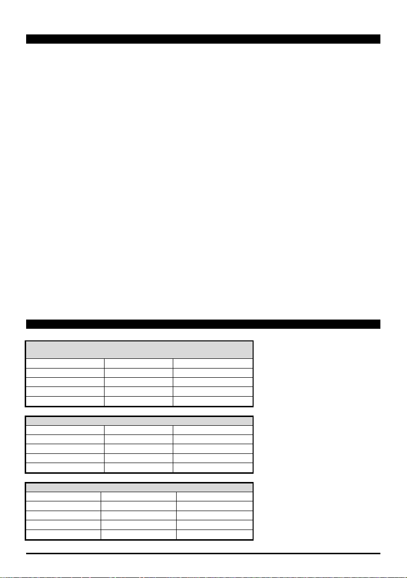
1592006207 XB570L GB r1.1 26.08.2015
XB570L
19
Cy1: for fast chilling and conservati on of foods at posi ti v e
temperature
CyS = tEP
iS2 = 5°C (41°F)
Pd3 = OFF
dbC = no
rS2 =-2°C (28°F)
dbH = yes
iS1 = 20°C (68°F)
Pd2 = 2.0 h
HdS = 3°C (37°F)
rS1= -10°C (14°F)
iS3 = 3°C (37°F)
Pd1 = 2.0 h
rS3=-2°C (28°F)
Cy2: for chilling and fast freezing of foods with holding
CyS = tEP
iS2 = 5°C (41°F)
Pd3 = 2.0 h
dbC = no
rS2= -2°C (28°F)
dbH = YES
iS1 = 10°C (50°F)
Pd2 = 2.0 h
HdS =-18°C (0°F)
rS1 = -10°C (14°F)
iS3=-18°C (0°F)
Pd1 = 2.0 h
rS3=-30°C (-22°F)
Cy3: direct fast freezing with holding
CyS = tEP
iS2=-18°C (0°F)
Pd3 = OFF
dbC = no
rS2=-30°C(-22°F)
dbH = yes
iS1 = -18°C (0°F)
Pd2 =OFF
HdS = -18°C (0°F)
rS1=-30°C (-22°F)
iS3 =-18°C (0°F)
Pd1 = 4.0
rS3=-30°C (-22°F)
18. TECHNICAL DATA
Housing: self extinguishing ABS
Case: frontal 185x38 mm; depth 70mm
Mounting: panel mounting in a 150x31mm panel cut-out
Frontal protection: IP65
Connections: screw terminal block ≤ 2.5mm
2
wiring
Power supply: 230Vac, ±10% Power absorption: 5VA max Display: dual display Inputs: 5 PTC or NTC probes Relay outputs:
Compressor: relay SPST 20(8)A or 8(3) A, 250Vac
Defrost: rela y 8(3)A, 250Vac
Fans: relay SPST 8(3)A, 250Vac
Light: relay SPST 16(6)A, 250Vac
Aux1: relay SPST 8(3)A, 250Vac
Aux2: relay SPST 16(6)A, 250Vac
Serial output: RS232 serial output for XB07PR printer connection
Serial output: TTL serial outp ut for monitoring system (MODBUS-RTU) protocol
Data storing: on the non-volatile memory (EEPROM)
Data storage: non-volatile memory (EEPROM)
Kinf of action: 1B
Pollution degree: normal
Software class: A
Operating temperature: 0 to 60°C (32 to 140°F)
Storage temperature: -30 to 85°C (-22 to 185°F)
Relative humidity: 20 to 85% (no condensing)
Measuring range: -55 to 50°C (-67 to 122°F)
NTC probe: -40 to 110°C (-40 to 230°F)
PTC probe: -50 to 150°C (-55 to 302°F)
Resolution: 0.1 °C or 1°F (selectable).
Accuracy of the controller at 25°C: ±0.3°C ±1digit
19. STANDARD VALUE OF THE CYCLES.
Page 91

1592006207 XB570L GB r1.1 26.08.2015
XB570L
20
Cy4: direct fast freezing without holding
CyS = tEP
iS2=-18°C (0°F)
Pd3 = OFF
dbC = no
rS2=-30°C (-22°F)
dbH = no
iS1 =-18°C (0°F)
Pd2 =OFF
HdS = OFF
rS1=-30°C (-22°F)
iS3=-18°C (0°F)
Pd1 = 4.0
rS3=-30°C (-22°F)
Page 92

1592006207 XB570L GB r1.1 26.08.2015
XB570L
21
20. STANDARD VALUES OF THE PARAMETERS.
Label
Value
Level
Description
Range
SEt 3 - - -
Set point
-50.0 to 50.0° C
Pr2
- - -
Pr1
not used
-
Hy
2.0
Pr1
Compressor hysteresis
0.1 to 12.0°C
AC 1 Pr2
Compressor restart delay
0 to 30 min
PAU 0 Pr2
Time of stand by
0 to 60 min
PFt
15
Pr2
Maximum accept a bl e dur ation of power failure
0 to 250 min
Con
15
Pr2
Compressor O N time with faulty probe
0 to 250 min
COF
10
Pr2
Compressor O FF time with faulty probe
0 to 250 min
rPo
0.0
Pr2
Thermostat probe calibration
-12.0 to 12.0° C
EPP
YES
Pr2
Evaporator probe presence
n; Y
EPo
0.0
Pr2
Evaporator probe calibration
-12.0 to 12.0° C
i1P
YES
Pr2
Insert probe 1 presence
n; Y
i1o
0.0
Pr2
Insert probe 1 calibration
-12.0 to 12.0° C
i2P n Pr2
Insert probe 2 presence
n; Y
i2o 0 Pr2
Insert probe 2 calibration
-12.0 to 12.0°C
i3P n Pr2
Insert probe 3 presence
n; Y
i3o 0 Pr2
Insert probe 3 calibration
-12.0 to 12.0° C
rEM
iPt
Pr2
Probe selection to stop chilling c ycle
iPt; rPt
CF
°C
Pr2
Temperatur e measurement unit
°C; °F
rES
dE
Pr2
Resolution (for °C):
in; dE
Lod
rP
Pr2
Upper display vi ew
rP;EP
rEd
rP
Pr2
View for rep
rP; EP; tiM; i1P; i2P; i3P
d1P
cL
Pr2
Door switch input polarity
OP; CL
odC
F-C
Pr2
Loads locked by door switch
no; FAn; CP; F-C
doA 5 Pr2
Open door al arm delay
da 0 a 254 min, 255=nu
dLc Y Pr2
Cycle block with open port
n; Y
rrd Y Pr2
Regulation restart after door open alarm
n; Y
d2F
EAL
Pr2
Second digital input function
EAL; bAL, ACy
d2P
cL
Pr2
Digital inp ut polarity
OP; CL
did 5 Pr2
Time delay for digital input alarm
0 to 255min
oA1
tMr
Pr2
Configuration of first auxiliary relay
ALL; Lig; AUS; C2; tMr
oA2
ALL
Pr2
Configurati on of second auxiliar y relay
ALL; Lig; AUS; C2; tMr
oA3
Lig
Pr2
Configurati on of third auxiliary relay
ALL; Lig; AUS; C2; tMr
2CH
C1
Pr2
Compressor setting during the holding
C1; C2; 1C2
OAt 3 Pr2
Second compressor switching on d elay
0 to 255 min
OAS
0.1
Pr2
Set point for s econd compressor
-50.0 to 50.0° C
OAH
2.0
Pr2
Differential for second compressor
-12.0 to 12.0° C
OAi
rP
Pr2
Probe selection for second compressor
rP; EP; i1P; i2P; i3P
OSt 0 Pr2
Auxiliary output timer
0 to 255 min
OSS
0.0
Pr2
Output set point delta
-50.0 to 50.0° C
OSH
2.0
Pr2
Differential for auxiliary output
-12.0 to 12.0° C
OSi
rP
Pr2
Probe selection for auxiliary out put
rP; EP; i1P; i2P; i3P
tdF
rE
Pr2
Defrost type
rE; in
idF
06:00
Pr2
Interval bet ween defrost cycles
0.1 to 24h00min
dtE 8 Pr2
Defrost termination temperature
-50.0 to 50.0° C
MdF
20
Pr2
Maximum length for defrost
0 to 255 min
dFd
rt
Pr2
Temperatur e displayed during def rost
rt; it; SET; dEF
Fdt 0 Pr2
Drip time
0 to 60 min
dAd
20
Pr2
Temperatur e display time after defrost
0 to 120 min
o-n; C1n; C2n; Cn; o-Y; C1Y;
C2Y; Cy
FnC c_n Pr2 Fan operating mod e during hold
Page 93

1592006207 XB570L GB r1.1 26.08.2015
XB570L
22
Label
Value
Level
Description
Range
FSt
30
Pr2
Fan stop tem pe rature
-50.0 to 50.0° C
AFH
2.0
Pr2
Differential for the stop temperature and for the alarm
0.1 to 25.0°C
Fnd 2 Pr2
Fan delay after defrost
0 to 255 min
ALU
30
Pr2
Maximum temper at ur e alar m
1.0 to 50.0°C
ALL
30
Pr2
Minimum temper at ur e alar m
1.0 to 50.0°C
ALd
15
Pr2
Temperatur e alar m del ay
0 to 255 min
EdA
30
Pr2
Alarm delay after defrost
0 to 255 min
tBA Y Pr2
Silencing alarm rel ay
n; Y
tCy
- - -
Pr1
Duration of l ast cycle
read only
tP1
- - -
Pr1
Duration of f irst phase
read only
tP2
- - -
Pr1
Duration of second phase
read only
tP3
- - -
Pr1
Duration of t hird phase
read only
Adr 1 Pr2
Indirizzo s eriale
0 to 247
bUt 2 Pr2
Buzzer activation at the end of the cycle
0 to 60 sec
tPb
ntC
Pr2
Type of probe
ntC; PtC
Atc
150
Pr2
Absolute high con d enser te mp erature threshold alarm
+50 to +150°C
btc
10
Pr2
Absolute low condenser temperature threshold alarm
+10 to +80°C
dAc 0 Pr2
Condenser alarm delay
1 to 250 sec (0=nu)
HyA
5.0
Pr2
Differential for condenser alarm (high and low)
0.1 to 12.0°C
bAc n Pr2
Machine shutdown with Atc alarm active
n; Y
bLc n Pr2
Machine shutdown with btc alarm active
n; Y
EPC
EP
Pr2
Evaporator probe configuration
EP, Co
i1c
i1
Pr2
Configurati on insertion probe 1:
i1, Co
i2c
i2
Pr2
Configurati on insertion probe 2:
i2, Co
i3c
i3
Pr2
Configurati on insertion probe 3:
i3, Co
b2
Cy1
Pr2
Configurati on key 2
nu, SSt, Cy1
b3
Cy2
Pr2
Configurati on key 3
nu, SCy, Cy2
b4
Aus
Pr2
Configurati on key 4
nu, Lig, AuS, OnF, dEf, Prn
b7
Hrd
Pr2
Configurati on key 7
nu, Prn, Hrd, Cy3
b8
OnF
Pr2
Configurati on key 8
nu, AuS, OnF, Lig, dEf
CCH
OFF
Pr2
Heating com pressor carter
Only-OFF, ALL
CCt 0 Pr2
Compressor carter heating activation time
0 to 250 min (0=nu)
dCy
SC
Pr2
Start cycle by digital input d2F
SC, Cy1, Cy2, Cy3, Cy4
Ptb
---
Pr2
Parameters original map
read only
rEL
3.1
Pr2
Firmware release
read only
dP2
- - -
Pr2
Evaporator threshold value (if configured)
read only
dP3
- - -
Pr2
Condenser t hreshold value (if configured)
read only
Page 94

1593006207 XB570L FR r1.0 26.08.2015
XB570L
2/24
XB590L(XB570L)
Page 95

1593006207 XB570L FR r1.0 26.08.2015
XB570L
3/24
1.1 LIRE CETTE NOTICE AVANT L'UTILISATION
1.2 PRÉCAUTIONS DE SÉCURITÉ
SOMMAIRE
1.
AVERTISSEMENTS GÉNÉRAUX 2
2.
DESCRIPTION GÉNÉRALE 3
3.
INSTALLATION ET MONTAGE 3
4.
SCHÉMA ÉLECTRIQUE 4
5.
PANNEAU AVANT 4
6.
GUIDE RAPIDE 4
7.
CYCLES DE REFROIDISSEMENT RAPIDE (1-4) 8
8.
DÉGIVRAGE 11
9.
GESTION DE L'HORLOGE 12
10.
PROGRAMMATION DES PARAMÈTRES 13
11.
PARAMÈTRES 14
12.
GESTION DE L'IMPRIMANTE 16
13.
BRANCHEMENTS ÉLECTRIQUES 19
14.
LIGNE SÉRIE 19
15.
CLÉ DE PROGRAMMATION 19
16.
SIGNALISATION DES ALARMES 20
17.
DONNÉES TECHNIQUES 21
18.
VALEURS DES PARAMÈTRES 22
1. AVERTISSEMENTS GÉNÉRAUX
• Cette notice fait partie intégrante du produit et doit être conservée avec l'appareil pour une consultation
rapide et facile.
• Le régulateur ne doit pas être utilisé avec des fonctions diverses de celles décrites ci-après, en particulier
il ne peut pas être utilisé com m e un disposit if de sécurité.
• Avant de procéder, vérifier les limites d'application.
• Dixe ll Srl se réserve le droit de varier la composition de ses pr oduits, sans le communique r au client, to ut
en garantissant toutefois le fonctionnement identique et inchangé des produits.
• Vér ifier le bon voltage avant le raccordement de l'appareil.
• Ne pas exposer l'unité à l'eau ou à l'humidité : utiliser le régulateur uniquement dans les limites de
fonctionnement prévues en évitant des échanges soudains de température unis à une humidité
atmosphérique élevée pour éviter la formation de condensation.
• Attention : avant de commencer toute maintenance, désactiver les branchements électriques de
l'instrument.
• L'i n strument ne do it jamais êtr e ouvert.
• En cas de dysfonctionnement ou de panne, réexpédier l'instrument au revendeur ou à la société « Dixell
S.r.l. » (voir l'adresse) avec une description précise de la panne.
• Tenir compte du courant maximum que l'on peut appliquer à chaque relais (voir Données Techniques).
• Positionner la sonde de manière qu'elle ne puisse pas être atteinte par l'utilisateur final.
• Faire en sorte que les câbles des sondes, de l'alimentation du régulateur, de l'alimentation des charges
soient séparés et suffisamment éloignés entre eux, sans se croiser et sans former de spirales.
• En cas d'applications dans des environnements industriels très critiques, il peut être utile d'adopter des
filtres de réseau (notre mod. FT1) en parallèle des charges inductives.
Page 96

1593006207 XB570L FR r1.0 26.08.2015
XB570L
4/24
3.1 MONTAGE
1
2
4
3
1 3 2
4
RG-LX gascke
(optional)
2. DESCRIPTION GÉNÉRALE
La série XB a été créée pour la congélation ou la surgélation des aliments en conformité avec les normes
internationales de sécurité. L'instrument dispose des fonctions suivantes :
• 4 cycles configurés en fonction des cycles de refroidissement rapide les plus communément utilisés ;
l'utilisateur peut modifier les paramètres internes pour améliorer à son gré le rendement de la machine.
• Chaque cycle peut être arrêté manuellement.
• Chaque cycle peut utiliser la sonde à piquer à introduire dans l'aliment.
• Durant un cycle, aucun refroid issement rapide n' est effectué pendant que les v entilateurs sont encore
allumés. Le dégivrage peut être effectué avant, après le refroidissement rapide ou pendant la
conservation (Holding).
• Chaque cycle peut être subdivisé en 3 phases avec des paramètres individuels.
• Il est possible d'utiliser la sortie de répétition du signal pour brancher un afficheur déporté.
• Le régulateur dispose d'une sortie pour l'imprimante modèle Dixell XB05PR. La régulation est effectuée
au moyen d'une horloge inter ne qui cal cule le temps.
3. INSTALLATION ET MONTAGE
Le montage du XB570L s'effectue sur panneau vertical, dans un trou de 150 x 31 mm, et fixé à l'aide de 2 vis
de ∅ 3 x 2 mm à une distance de 165 mm. Afin d'obtenir une protection frontale IP65, utiliser le caoutchouc
de protection frontale mod. RG-L (en option).
La plage de tem pérature admi se pour un bon fonct ionnement est c omprise entre 0 et 60 °C. Éviter les li eux
soumis à de fortes vibrations, aux gaz corrosifs, à une saleté ou à une humidité excessive. Les mêmes
indications valent également pour les sondes. Permettre l'aération de la zone située à proximité des fentes de
refroidissement.
Page 97

1593006207 XB570L FR r1.0 26.08.2015
XB570L
5/24
3.2 GABARIT DE PERÇAGE
6.1 AFFICHEUR
165
+1
150
+0.5
-0
Ø3 x2
31
-1
-0
+0.5
4. SCHÉMA ÉLECTRIQUE
Les sondes à piquer 2 et 3 (17-18-19) sont d ésactivées en usine.
Les sorties relais 9-10 (oA3)=lumière, 7-8 (oA1)=Aux, 1-2(oA2)=alarme sont configurées de cette manière en
usine.
Le microrupteur porte doit être branché aux contacts 25-26.
5. PANNEAU AVANT
6. GUIDE RAPIDE
Chaque icône allumée indique une charge
ou un état d'activation.
Une icône clignotante indique une
temporisation d'activation de paramètre
ou d'entrée digitale.
Grand : température de l'air.
Petit : timer ou sonde à piquer
Icônes d'état.
Page 98

1593006207 XB570L FR r1.0 26.08.2015
XB570L
6/24
chaque pression l'écran affiche la
: appuyer et
. La LED jaune correspondante
automatiquement après la durée de
pour accéder au menu horloge et
configurer la valeur au moyen des
attendre 5 s.
CONFIGURER LA TEMPÉRATURE DE
Si un cycle de refroidissement rapide
de consigne de maintien) sera alors
Valeur du point de
6.2 CLAVIER EN STAND-BY
SÉLECTIONNER UN CYCLE :
Appuyer en séquence sur la touche (3)
pour sélectionner un cycle, lors de
sélection 1, 2, 3, 4, H (cycle de maintien)
DÉMARRER UN CYCLE
relâcher le bouton (2) START/STOP
s'allume.
ARRÊT MANUEL : appuyer et relâcher le
bouton (2) START/STOP , la LED
jaune clignote. Le redémarrage s'effectue
en appuyant sur la touche ou
pause PAU.
ARRÊT DÉFINITIF : maintenir appuyé le
bouton (2) START/STOP , la LED
jaune s'éteint.
ONFIGURER L'HORLOGE (RTC)
Maintenir appuyée la touche DOWN (5)
config urer la date et l 'heure.
Utilis er les fl èches pour se d éplace r entre
les paramètres.
-
Pour modifier : appuyer sur SET, p uis
flèches.
-
Pour confirmer : appuyer sur SET.
-
Pour quitter le menu : appuyer
simultanément sur les t ouches flèche ou
MAINTIEN À LA FIN DU CYCLE
prévoit le maintien, appuyer puis relâcher
la touche SET (6), et sa valeur HdS (point
Utiliser les flèc he s pour
afficher les éléments :
-
Min= minutes
-
Hou= heure
-
daY= jour
-
Mon= mois
-
YEA= année
-
tiM= horaire US/EU
(Europe)
affichée pendant 5 secondes.
Pour modifier HdS : pendant les 5
secondes, maintenir appuyée la touche
SET jusqu'au clignotement de HdS,
utiliser les flèches pour modifier la valeur.
Pour confirmer : appuyer à nouveau sur
la touche SET.
consigne de maintien qui
démarrera à la fin du
cycle 1.
Page 99

1593006207 XB570L FR r1.0 26.08.2015
XB570L
6/24
AFFICHEUR DES TEMPÉRATURES :
les sondes iP2 et iP3 sont affichées en
séquence, si activées, puis la durée
maximale qui reste pou r terminer le cy cle.
en appuyant une fois sur la flèche EN
HAUT (1), l'état de la phase en cours
dant 5 secondes. Si une
Si les phases sont
activées :
PH1= phase 1 du cycle 1
PH2= phase 2 du cycle 1
PH3= phase 3 du cycle 1
appuyée la touche SET (6) jusqu'au
Ensuite, utiliser les touches flèche et
appuyer à nouveau sur la touche SET
CHER LES VALEURS DE
Lorsqu'un maintien est sélectionné,
l'icône H allumée, en appuyant sur la
(6), la valeur suivante est
= valeur du thermostat de la
: avant 5 secondes,
ppuyer sur la touche SET pendant 2
secondes, la LED de la touche (6) et
: appuyer à
6.3 LE CLAVIER DURANT LE FONCTIONNEMENT D'UN CYCLE
6.4 UTILISATION DU CLAVIER AVEC LE CYCLE DE MAINTIEN (H)
Après avoir démarré un cycle de refroidissement rapide, l'instrument répond avec cette interface.
Afficheur supérieur : sonde d'ambiance.
Afficheur inférieur : sonde à piquer (si
activée) ou le compte à rebours du temps
maximal.
CHANGEMENT DE L'AFFICHAGE : en
appuyant sur la touche flèche EN BAS (5),
AFFICHAGE DE LA PHASE EN COURS :
s'affichera pen
phase n'es t pas activée, elle n e sera pas
affichée.
CONTRÔLER LES VALEURS DE
RÉGLAGE
En appuyant sur la touche SET en
séquence :
1)
rSI = valeur du thermostat.
2)
iSI = valeur de fin de phase pour la
sonde à piquer.
3)
retour à l'affichage normal.
MODIFIER LES VALEURS DE RÉGLAGE
Lorsque rSI ou iSI sont affichés, maintenir
clignotement de la LED jaune de la touche
et l'inscription sur l'afficheur.
pour confirmer.
Le démarrage du cycle de maintien s'effectuer en sélectionnan t H et en appuy ant sur la touche START.
AFFI
RÉGLAGE
touche SET
affichée :
- SEtH
cellule en phase de maintien.
MODIFICATION
a
l'inscription affichée clignotent.
Modifie r la vale ur avec l es touc hes flèc he
(1 et 6).
CONFIRMER et QUITTER
nouveau sur SET.
Page 100

1593006207 XB570L FR r1.0 26.08.2015
XB570L
7/24
LUMIÈRE (4): en l'appuyant et la
lumière. La LED jaune de la touche
on lance l'impression à des intervalles
selon la configuration.
Appuyer sur la touche (7) pendant
quelques secondes pour accéder au
Pour sélectionner : flèche EN HAUT ou
: appuyer
ou attendre 5 secondes.
Les touches flèche défilent les
+
+
Accès à la programmation en stand-by.
droite.
+
6.5 AUTRES TOUCHES
6.6 TOUCHES COMBINÉES
relâcha nt, on active o u désactive l e relais
indique l'état du relais.
AUX (8): ): en appuyant et relâchant la
touche A UX, on active/dés active le relais
auxiliaire (si configuré)
IMPRIMANTE/H (7) : en appuyant sur la
touche, s i ell e est reli ée à un e impr ima nte,
CONFIGURATION DE L'IMPRIMANTE
menu imprimante, l'inscription itP est
affichée.
EN BAS
Pour modifier : appuyer sur SET, puis
sur les touches flèche.
Pour confirmer : appuyer sur SET.
Pour quitter le menu
simultanément sur SE T + flèche EN HAUT
La combinaison verrouille (PoF) ou déverrouille (Pon) le clavier.
Depuis le nivea u « Pr2 », i l est pos sibl e d'aff iche r ou de cac her e n « Pr1 » un
paramètre. La présence de ce dernier est indiquée par un petit point à sa
En phase de programmation, retour au menu précédent.
inscriptions suivantes :
-
itP= interva lle d'impression.
-
PbP= date d'impression.
-
PAr= impression des
paramètres.
-
Cyc= impression des
paramèt res des cycles.
-
PtH= impression pendant le
maintien.
-
PrS= paramètres du niveau
Pr1 ou Pr2.
-
Pnu= nombre d'impressions.
 Loading...