

Page 1
Blast Chillers/Freezers
BLC3, BLC5, BLC10, BLC14
Users manual UK 1
0
Page 2

1
Page 3

CONTENT
ENGLISH
1.REGULATIONS AND GENERAL INSTRUCTIONS .................................................................................. 1
1.1 General information ................................................................................................................................... 1
1.2 Replacement of Parts ................................................................................................................................ 1
1.3 Description of the Applianc e ..................................................................................................................... 1
1.4 Features Plate............................................................................................................................................. 2
2. SAFETY.................................................................................................................................................... 3
3.RECOMMENDATIONS FO R USE ............................................................................................................ 4
Prolonged Inactivity .......................................................................................................................................... 4
Blast chilling Cycle ............................................................................................................................................ 5
Shock freezing Cycle ........................................................................................................................................ 5
4.CLEANI NG AND MAINTENAN CE ............................................................................................................ 6
4.1 Recommendations for Cleaning and Mainten ance ............................................................................... 6
4.2 Routine Maintenan ce ................................................................................................................................. 6
4.3 Extraordinary maintenance ....................................................................................................................... 6
5.TROUBLE SHOOTING ............................................................................................................................. 8
6. INSTALLATION ........................................................................................................................................ 9
6.1 Packing And Unpacking ............................................................................................................................ 9
6.2 Installation ................................................................................................................................................... 9
6.3 Electric Power Supply Connection ........................................................................................................ 10
6.4 Inspection .................................................................................................................................................. 10
7.DISPOAL OF THE APPLIANCE ............................................................................................................. 11
8.REFRIGERANT RECHNICAL CARD ..................................................................................................... 11
XB570L BLAST CHI LL& FR EEE ZE R CONT RO LL ER ............................................................................. 12
9. General Features ................................................................................................................................... 12
10. Mounting & Instal lation ......................................................................................................................... 12
1 1. Electrical Connections .......................................................................................................................... 12
11.1 PROBES CONNECTION ...................................................................................................................... 13
12. Connections ......................................................................................................................................... 13
13. Frontal panel......................................................................................................................................... 13
14. QUICK START ...................................................................................................................................... 13
14.1 DISPLAY .................................................................................................................................................. 13
14.2 KEYBOARD IN STAND-BY .................................................................................................................. 14
14.3 KEYBOARD WHEN A CYCLE 1,2,3,4 IS RUNNING ....................................................................... 15
14.4 KEYBOARD WHEN THE HOLDING CYCLE IS RUNNING ( H) ..................................................... 16
14.5 OTHER KEYS......................................................................................................................................... 16
14.6 HOW TO START A MANUAL DEFROST .......................................................................................... 17
14.7 OTHER FUNCTIONS OF KEYBOARD .............................................................................................. 17
14.8 MEANING OF THE LEDS’ .................................................................................................................... 17
15. How To Select A Cycle ......................................................................................................................... 18
15.1 HOW TO MODIFY A CYCLE ............................................................................................................... 18
16. Parameters ........................................................................................................................................... 18
PROBES .......................................................................................................................................................... 19
1
Page 4

DISPLAY AND MEASUREMENT UNIT ...................................................................................................... 19
DIGITAL INPUTS ............................................................................................................................................ 19
AUXILIARY RELAY CONFIGURATION ...................................................................................................... 20
SECOND REL AY MANAGEMENT ............................................................................................................... 20
AUXILIARY RELAY MANAGEMENT ........................................................................................................... 21
DEFROST ........................................................................................................................................................ 21
FANS ................................................................................................................................................................ 21
TEMPERATU RE ALARMS............................................................................................................................ 22
CYCLE LOG .................................................................................................................................................... 22
OTHER ............................................................................................................................................................. 22
17. How A Cycle Is Done ........................................................................................................................... 22
17.1 CONFIG URABLE CYCLE PARAMETERS ........................................................................................ 23
17.2 HOW TO USE THE INSERT PROBES .............................................................................................. 23
17.3 EXAMPL E OF A B L AST CHILLER CYCLE. ...................................................................................... 23
18. Installation and mounti ng ..................................................................................................................... 25
18.1 CUT OUT ................................................................................................................................................. 25
18.2 MOUNTING............................................................................................................................................. 25
19. XB07PR - Printer (opti onal) ................................................................................................................. 26
19.1 PRINTER DIMENSIONS ...................................................................................................................... 26
19.2 PRINTER MOUNTING .......................................................................................................................... 26
19.3 CONNECTION TO THE XB570L – XB07PR ..................................................................................... 27
20. Electrical connection s .......................................................................................................................... 27
20.1 PROBE CONNECTIONS ...................................................................................................................... 27
21. TTL Serial line ...................................................................................................................................... 27
22. Use of the programmi ng “ HOT KEY” ................................................................................................... 27
22.1 DOWNLOAD (FROM THE “HOT KEY” TO THE INSTRUMENT) .................................................. 27
22.2 UPLOAD (FROM THE INSTRUMENT TO THE “HOT KEY”) .......................................................... 28
23. ALARM SIGNALS ................................................................................................................................ 28
24. Technical data ...................................................................................................................................... 29
25. Standard Value of the cycles ............................................................................................................... 29
26. Standard Values of the parameters ..................................................................................................... 30
2
Page 5

1.REGULATIONS AND GENERAL INSTRUCTIONS
1.1 General information
This manual has been designed by the manufacturer to provide the necessary inf ormation to those who
are authorized to interact with the appliance.
The persons receiving the inf ormation must read it caref ul ly and apply it strictly.
Reading the information contained in this document will allow the user to prevent risks to personal health
and safety.
Keep this manual for the entire operating life of the equipment in a place which is well-known and easily
accessible, so that it is always available when its consultation beco me s necessary.
Particular symbols have been used to highlight some parts of the text that are very important or to
indicate some important specifications. Their meanings are given below:
Indicates important information regarding safety. Behave appropriately so as not to risk the health
and safety of persons or cause damage.
Indicates particularly important t echnical information that must not be ignored
1.2 Repl ac em ent of Parts
Activate all envisioned safety devices b ef or e car r ying out any replacement intervention.
In particular, deactivate the electrical power supply using the differential isolating switch.
All responsibility is declined for injury to persons or damage to com ponents deriving from the use of
non-original spare parts and interventions which could modify the safety requisites,without authorization
of the manufacturer .
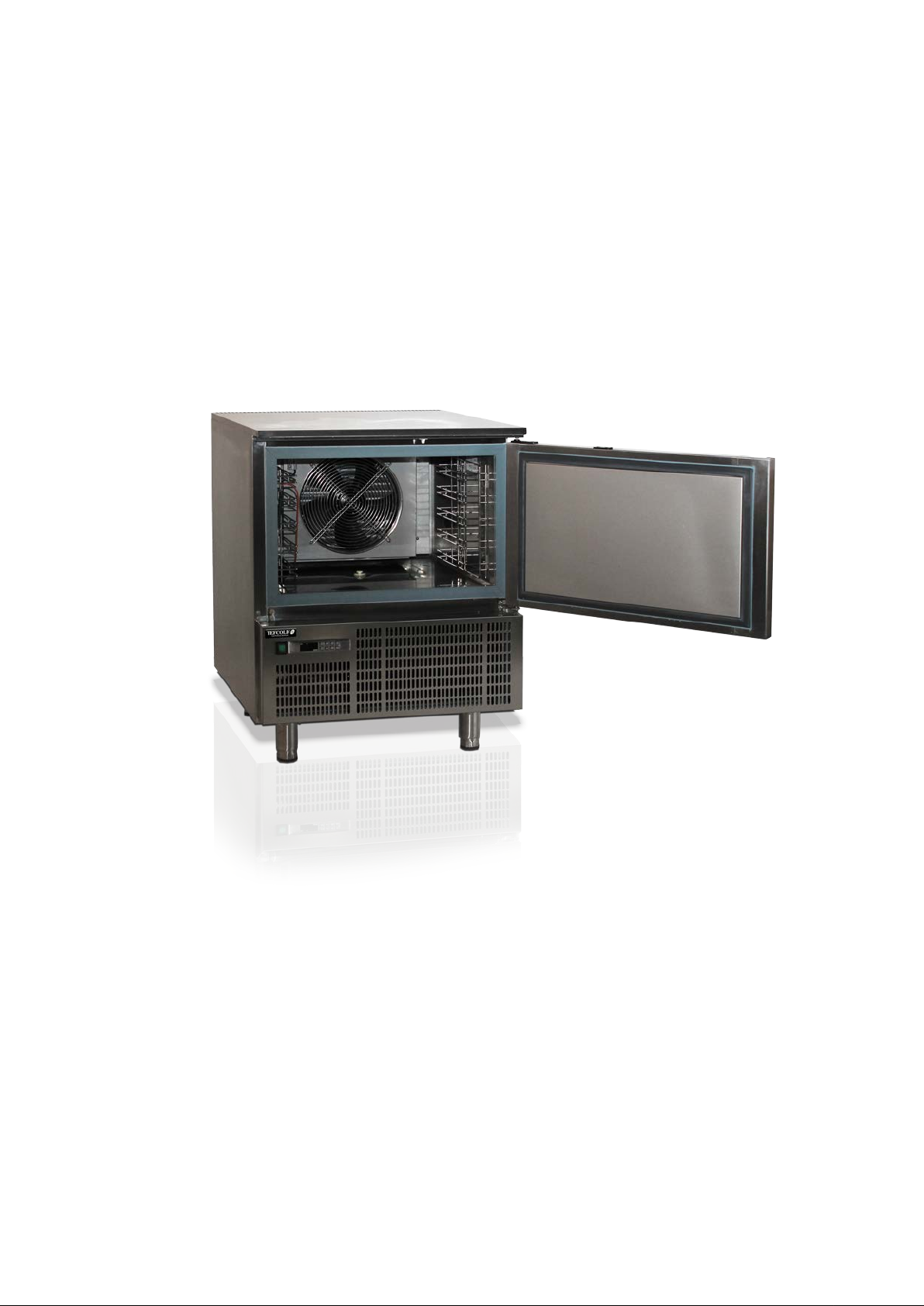
1.3 Descript ion of the Appliance
The Blast chiller & freezer, from now on defined as applian ce, has been designed and built t o c ool and/or
freeze foodstuffs in t he professional catering ambit.
1) Condensation area: it is pos itioned in the lower part and is characterized by t he pr es ence of the
condensing unit.
2) Electric area: it is positioned in the lower part of the appliance and contains the control and power
supply components as well as electric wiring.
3) Evaporation area: it is situated inside the refrigerated compartment in the rear and is characterized
by the evaporating unit.
4) Storage area: it is situated inside the re frig er ated compartment and is destined for the cooling and/or
freezing of foodstuffs.
1
Page 6
3-4
1
2
A
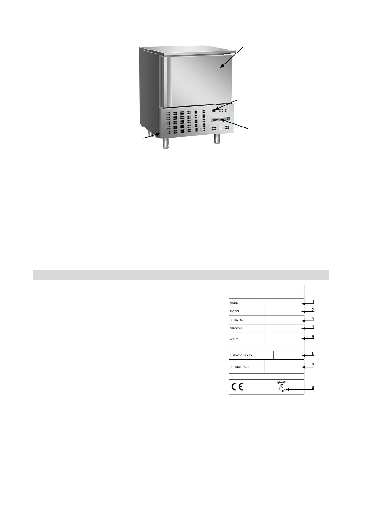
The lower part is also distinguished by a control panel (A) that allows access t o t he electric parts; there is
a vertically-opening door in the front, which closes the refrigerated comp ar tment hermetically .
Depending on requirements, the appliance is produced in several ver sions.
BLC3 BLAST CHILLER/FREEZER
Model suitable to contain 3 trays with blast chilling capacity of 12kg and 8 kg in shock freezing.
BLC5 BLAST CHILLER/FREEZER
Model suitable to contain 5 trays with blast chilling capacity of 18k g and 14kg in shock freezing.
BLC10 BLAST CHILLER/FREEZER
Model suitable to contain 10 trays with blast chilling capacity of 40kg and 28 kg in shoc k freezing.
BLC14 BLAST CHILLER/FREEZER
Model suitable to contain 14 trays with blast chilling capacity of 55kg and 38kg in shock fre ezing.
1.4 Features Plate
The identification plate shown is applied directly onto
the appliance. It st at es t he reference and all indications
indispensable for workin g in safety.
(1) Appliance code
(2) Description of the Appliance
(3) Serial number
(4) Power supply voltage and frequ enc y
(5) Electrical absorption
(6) Climatic class
(7) Type and Amount of refrigerant gas
(8) WEEE symbol
2
Page 7

2. SAFETY
It is recommended to carefully read the instructions and warnings contained in this manual before
using the appliance. The informat io n c ontained in the manual is fundamental for the safety of use and for
machine maintenance.
Keep this manual carefull y so that it can be Consulted when necessary.
The electric plant has been designed in compliance with the IEC EN 60335-2-89 and EN 60335-1
standard.
Specific adhesives highlight the presence of mains voltage in the proximity of areas(however
protected)with risks of an electrical nature.
Before the connection, ensure the presence of an omni polar switch with minimum contacts opening
equal to 3 mm in the mains pow er supply upst ream from the applianc e (requested for appliances supplied
without plug to connect to the fi xed plant).
In the design and construction phase, the manufacturer has paid particular attention to the aspects that
can cause risks to safety and health of persons that interact with the appliance.
Carefully read the instructions stated in the manual supplied and those applied directly to the machine,
and particularly r espec t t hose r egarding Safety.
Don’t tamper or eliminate the installed safety devices. Failure to comply with this requisite can Lead to
serious risks for personal health and safety.
It is recommended to simulate some test manoeuvers in order to identify the controls, in particular those
relative to switch-on and sw it ch-off and their main functions.
The appliance is only destined for the use for which it has been designed; any other use must be
considered improper.
The manufacturer declines all liability for any damage to objects or injury to persons owing to
improper or incorrect use.
All maintenance interventions that require precise technical skill or particular ability must be
performed exclusively by qualified staff.
When using the appliance, never obstruct the air inlet when the appliance is on,so as not to
compromise its per formance and safety.
Never stretch the power cabl e.
In order to guarantee hy giene and pr ot ect t he food stuffs from contaminatio n, t he e lements that come into
direct or indirect contact with the foodstuffs must be cleaned very well along with the surrounding
areas .These operations must only be performed using detergents that can be used with foodstuffs,
3
Page 8

avoiding inflammable products or those that contain substa nces that are harmful to personal health.
In the case of prolonged inactivity, as well as disconnecting all the supply lines, it is necessary to
accurately clean all inter nal and external par ts of the appliance.
3.RECOMMENDATIONS FOR USE
Prolonged Inact ivity
If the appliance remains inactive for a long period, proceed as follows
1. Use the automatic isolating switch to deactivate connection to the main electrical line.
2. Clean the appliance and surrounding areas thoroughly.
3. Spread a thin layer of cooking oi l onto t he stainless steel surfaces
4. Carry out all maintenance operations
5. Leave the doors ajar to prevent the formation of mould and /or unpleasant odour.
Recommendations for normal use
In order to ensure correct use of the appliance, it is good practice to apply the following
recommendations:
Do not obstruct the zone in front of the condensing unit in order to favour heat disposal from the
condenser to a maximum.
Always keep the front of the con denser clean.
Do not insert foodstuffs t hat ar e we ll abov e the t e m perature of 65 ℃. As well as initially overloading the
machine it can make protections intervene that prolong temperature descent times. If possible , a brief
external period is useful to lower the temperature t o ac ceptable values.
Check the planarity of the app lia nce r est surface.
Do not stack the materials to be preserved in contact with the internal walls .so blocking the
circulation of air , which gu arantees un iformity of the interna l temperatur e of the refrigerate d compar tment .
There must be a suffici ent sp ace b etw een the ba sin s and t ray s used in ord er to guarant ee a sufficient
flow of cold air on the entire pr oduct. Therefore avoid the following positions of trays and/or basins stated
below.
Never obstruct the inlet of t he evaporator fans.
Products that are more difficult to chill because of their composition and size shoul d be placed in the
centre.
Limit the number of times and the duration of time the doors are opened.
Blast chilling data r efer to stand ard product s ( low fat cont ent )with a th icknes s below 5 0 mm: ther efore
avoid overlaying products or the insertion of pieces with a much higher thickness, This would ,in fact,
lead to an extension of blast chilling times .Always distribute the product well on the trays or basins or in
the case of thick pieces decrease the amount to blast chill.
4
Page 9

After blast chilling/shock freezing the product, it can be stored in a preservation cabinet after having
℃
℃
been duly protected .A tag should be applied describing the contents of the product, blast chilling/shock
freezing date and exp iry d at e. When the pr oduct has been bl ast ch ille d it must be pr es erv ed at a c onstant
+2
temperature of
-20
。
,while if it has been shock frozen it must be preserv ed at a const ant t emperat ure of
The chiller should be used for st or age for short periods only.
T o preve nt bacterial co ntaminati on or contami nation of any other bi ological na ture,
the needle probe must be disinfected af ter use.
To extract the product that has undergone blast chilling or shock freezing ,always wear gloves to
protect the hands ,as “bur ns” m ay occur form the cold.
Blast chilling Cycle
With this operating modality the chiller keeps the temperature of the refrigerating compartment close to
zero during the entire chill i ng pr ocess in
order to ensure a gradual drop in the temperature of the product to +3℃。In this way ,ice crystals do not
form on the surface of the product .This blast chilling method should be used preferably for products that
are not packed and whose physical/organoleptic characteristics could be damaged by the formation of
superficial ice (e.g. fish)
Shock freezing Cycle
With this blast chilling modality the blast chiller maintains the temperature at a negative value below
-18℃,which is the end te mperatur e of shoc k freez ing .For shoc k freezing t o be succes sful and fast, food
should be in small pieces, especiall y if it has a high fat content. The largest pieces should be placed in
central trays .If it takes longer than standard time to shock freeze and the sizes cannot be reduced,
decrease the quantity and precool the chiller compartment by starting an empty shock freezing cycle
before shock freezing the pr oduct.
5
Page 10

4.CLEANING AND MAINTENANCE
4.1 Recommendations fo r Cleaning and Maintenance
Activate all envisioned safet y dev ices before car ry ing out any mainte nan ce int erv entions, I n par ticu lar,
deactivate the electrica l power supply using the automatic isolating switch.
4.2 Routine Maintenance
Routine maintenance consists of dai ly cleaning of all the parts which can into contact with foodstuffs and
the periodic maintenance of the burners, nozzles and draining pipes.
Correct maintenance allows the user to maximize performance levels and operating life and constantly
maintain safety r equirements.
Do not spray the applianc e w ith dir ect j ets of water or using high pressure appliances.
Do not use iron wool. brushes or scrapers to clean the stainless steel as ferrous particles could be
deposited which ,on oxidiz ing, could lead to rust.
To remove hardened residues, use wooden or plastic spatulas or abrasive rubber pads.
During long periods of inactivity , spread a protective layer on all stainless steel surfaces by wiping them
with a cloth soaked in Vaseline oil and airing the roo ms p er iodically .
Do not use products which contain substances which are harmful and dangerous for personal health
(solvents. petrol et c)
At the end of the day it is advisable to clean:
the cooling compartment
the appliance
4.3 Extraordinary maintenance
Have the following operati ons c arr ied out periodically by specialized staff:
Check the perfect sealing of the door gaskets and replace them if necessary.
Check that the electric connections have not loosened.
Check the efficiency of the heating element resistance.
Check functioning of the board and probes.
Check the efficiency of the electrical system.
Clean the evaporator.
Clean the condenser.
Cleaning the evaporator
Clean the evaporator periodically.
6
Page 11
As the fins of the evaporator are very sharp. always wear protectiv e gloves for the next phases .Only
a brush must be used for cleaning :do not use jets of liquid or sharp instruments.
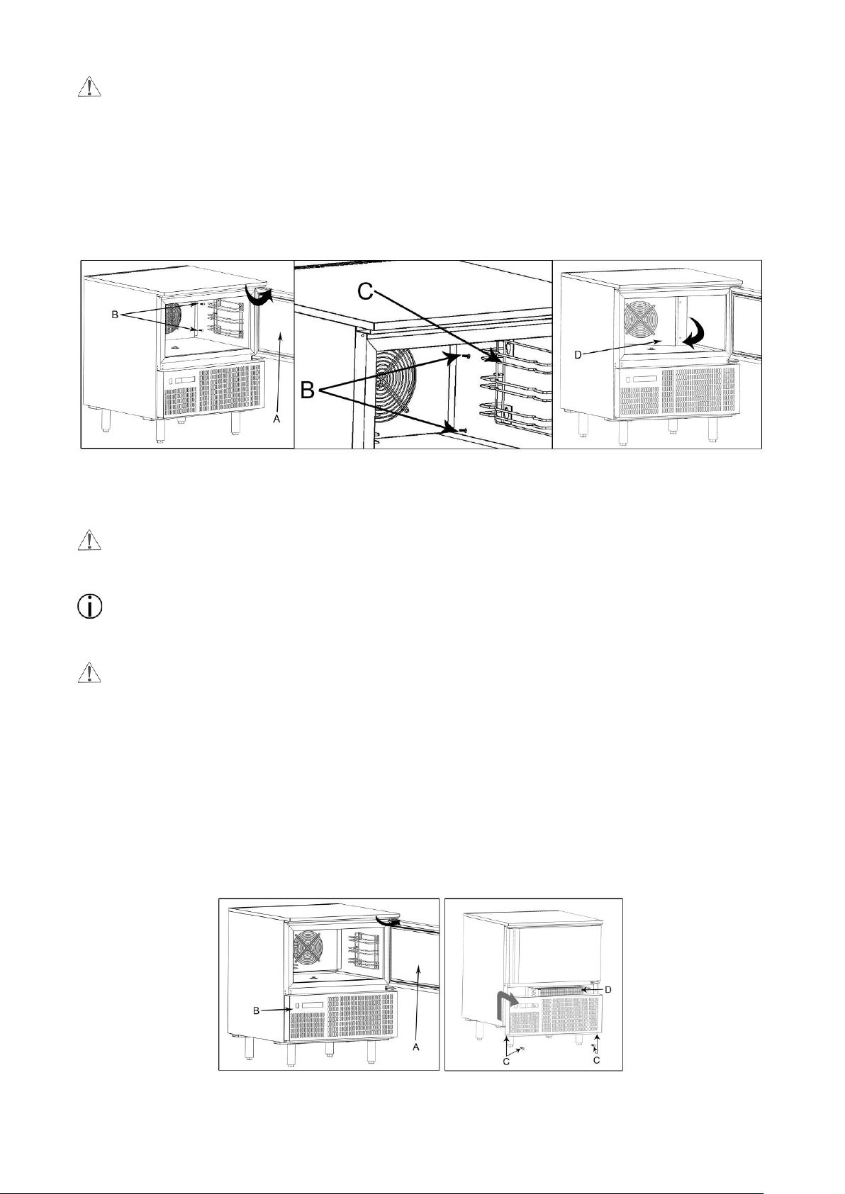
To access the evaporator procee d as f ollows:
1. Open the do or ( A) of the appliance.
2. Loosen the t w o sc r ew s ( B)on the right of the deflector.
3. Remov e t he r unner s(C)
4. Turn the deflector(D) to the left.
Clean the condenser
Clean the condenser periodically
As the fins of the condenser are very sharp, always wear protective gloves for the next phases. Use
protective masks and glas ses in the presence of dust
Whenever the condenser has a deposi t of dust in correspondence with the fins, this can be removed
using a suction device or with a brush applied, using a vertical movement along the direction of the fins.
No other instruments must be used, which may deform the fins and therefore the efficiency of the
appliance.
To clean, proceed as follows:
1. Open the door (A) of the appliances.
2. Remove the lower panel(B) from the technical compartment: to do this, remove the screw
fasteners(C)
3. It is now possible to clean the finned part of the condenser (D) using suitable tools and protecti on
devices.
4. After cleaning, close the control panel an d f ix it with the screws removed beforehand.
7
Page 12

5.TROUBLE SHOOTING
centre
centre
centre
The information shown below aims to help with the identification and correction of any anomalies and
malfunctions which could occur duri ng use. So me of these pr oblems can be re solved by the user. For the
others, precise skill is req uir ed and they must therefore only be carried out by qualified staff.
Problem
The refrigerator unit does not
start
The refrigerator unit funct i ons
continuously, cooling
insufficiently
Causes Solutions
Check the power supply cabl e
No voltage
Check the correct connect ion o f
Other causes
contact the after-sales centre
Room too hot Air the environment
Dirty condenser Clean the condenser
Insufficient door sealing Check the gaskets
Insufficient quantity of
refrigerant gas
Check fuses
the appliance
If the problem persists,
Contact the after -sales
The refrigerator unit does not
stop
Presence of ice inside the
evaporator
Appliance noise Persistent vibrations
Condenser fan at a standstill
Evaporator fan standstill
Probe faulty
Circuit board fault
Contact the after -sales
Contact the after -sales
centre
Contact the after -sales
centre
Contact the after -sales
Carry out a defrosting cy cl e
possibly with the door open
If the problem persists,
contact the after-sales centre
Check there is no contact
between the appliance and
other objects inside or outside
8
Page 13

6. INSTALLATION
6.1 Packing And Unpacking
Handle and install the appliance respecting the information provided by the manufacturer, shown directly
on the packaging, on t he appliance and in this man ual.
The lifting and transportation system of the packaged product envisions the use of a fork -lift truck or a
pallet stacker. W hen using these, particular attention must be paid to balancing the weight in order to
prevent the risk of overtur nin g( avoid excessive tilting!).
ATTENTION: When inserting the lifting device, pay attention to the power supply cable and the
position of the feet.
The packaging is m ade of cardboard and the pallet of plywood. A series of symbols is printed on the
cardboard packagin g which highl ights, i n accordanc e with internat ional st anda rds, the prov isions to w hich
the appliances are subjected during loading, unloading, transport and storage.
On delivery, check that the packaging is intact and has not undergone any damage during tr ansportation.
The transportation company must be notified of any damage immedi at ely.
The appliance must be unpacked as soon as possib le to chec k that it is int act and unda maged. Do not cut
the cardboard with sharp tools so as not to damage to the steel panels underneath.
Pull the cardboard pa ckaging upwards.
After having unp acked the appliance, check that the features correspond to those requested in the or der ;
Contact the dealer imm ediately if there are any anomalies.
Packaging elements (nylon bags, polystyrene foam, staples…) must not be left within reach of
children.
Remove the protective PV C fil m from the internal and external walls, avoiding the use of metal tools.
6.2 Installation
All the installation phases must be considered, from the moment of creation of t he general plan.
The installation area must be equipped with all power supply and production residue drainage
connections and must be suitably lit and respect current laws regarding hygiene and sanitary
requirements.
The performance of the appliance is guaranteed with a room temperature of 32℃. A higher
9
Page 14

temperature can compromise its performance and, in more serious cases, cause the appliance’s
protections to start up.
Therefore, consider t he m ost cr itical r oo m cond itio ns t hat can be rea che d in t h at posit ion be fore ma king a
choice.
Level the appliance by act ing on the individual feet.
This appliance can only be instal led and operate in rooms which are permanently ventilated, in order
to guarantee correct operation.
Connect and leave for a certain peri od of time (at least 2 hours) before checking functioning. During
transport it is probable that the compressor lubricant oil has entered the refrigerant circuit blocking the
capillary: as a consequence the appliance will function for a certain peri od of time without producing cold
until the oil has returned to the compressor.
ATTENTION: the appliance requires the mini m um functioning spaces, as shown in the attachments.
The defrosting water and the water that forms at the bottom of the refrigerating compartment during
operation or during periodical internal cleaning must be drained through a prearranged hose with a
minimum diameter 3/4 connected to the hose at the bottom of the chiller.
A drai n t r ap should also be guaranteed. The drain must be in comp lia nce with S tandards in force.
6.3 Electric P ower Supply Connection
Connection must be carried out by authorized and qualified staff, respecting the current laws regarding
the subject and using app r opr iate prescribed material.
Before connecting the appliance to the electric mains, check that the voltage and the frequency
correspond to the dat a stated on the registration plate applied in the rear of t he appliance.
Before connection, ensure the presence of a relevant differential switch with adequate power in the
mains power supply, upstream from the appliance, i n order to protect the appliance from overloads or
short circuits
6.4 Inspection
The appliance is delivered in conditions such that it can be st ar ted-up by the user.
This functionality is guaranteed by passing the tests (electric inspection-functional inspection,
appearance inspection) and relative certification through the specific att achments.
At least the following should be checked after installation:
Check the electric connec tions.
Check the functionality and efficiency of drains.
Check that there are no to ols or mater ials lef t in the app liance th at could jeo pa rdize it s funct ionality or
even damage the machine.
Have the appliance perfor m at least one complete chill blasting/shock freezing cycle.
10
Page 15

7.DISPOAL OF THE APPLIANCE
This appliance is marked in compliance with the 2002/96/EC European Directive. WASTE
ELECTRICAL AND ELECTRIC EQUIPMENT (WEEE).
By assuring that this product is dis posed of correctly , the user contributes to preventing the potentia l
negative consequences on the environment and health.
The
product must not be treated as domestic waste but must be taken to suitable collection points for the
recycling of electric and el ect r onic appliances.
Dispose of it following local regulations regard ing waste disposal.
For further information regarding the treatment, recovery and recycling of this product, contact the
relevant local office, the domest ic w aste coll ection serv ice or the shop w here the product was pur chas ed.
symbol found on the product or on the accompanying documentation indicates that this
8.REFRIGERANT RECHNICAL CARD
The refrigerant used in the machine is R404a fluid. Below find the components of the fluid:
PENTAFLUOROETANE (HFC R125)44%
ETHANE 1, 1, 1-TRIFLUORO (HFC R143A)52%
ETHANE 1, 1, 1, 2 TERAFLUORO (HFC R134A)4%
IDENTIFICATION OF DANGERS
The rapid evaporation of the liquid can cause freezing. The inhalation of high concentrations of vapour
can cause irregular heartbeat, short term narcotic effects (including vertigo , headache and mental
confusion), fainting and d eat h.
Effects to the eyes: Freezing or cold bur ns caused by contact with the liquid.
Effects on the skin: Freezing or cold bur ns caused by contact with the liquid.
Effects of ingestion. Ingest ion is n ot considered a means of exposure.
FIRST AID
Eyes: In the case of contact, wash the eye well using a l arge amount of water for at least 15 minutes.
Consult a doctor.
Effects on the skin: Wash with water for at least 15 minutes after excessive contact. If necessary, cure
freezing by gently warming the area in question. Consult a doctor in the case of irritation.
Ingestion: Ingestion is not considered a means if exposure.
Inhalation: If large concentrations are inhaled, go into the open air, Keep the person calm. If the
person cannot breath, perform artificial respiration. If respiration is difficult, apply oxygen.
Consult a doctor.
11
Page 16

XB570L
BLAST CHILL&FREEEZER CONTROLLER
9. General Features
The series XB has been creat ed f or fast chilling or freezing goods a ccor ding to international food safety
standards.
There are FOUR types of cy cles:
The CYCLES: Cy1, Cy2, Cy3, Cy4 are pre-set according to the m ost common cycles used in food -
safety applications; the user can select one of them according to his own requirement s and modify
it as he wants.
Any cycle can be manually terminated before the normal.
Any cycle can use the insert probe, it measures the internal temperature of the product.
During the Cycle there are no defrosts and the fans are always on, a defrost cycle can be done
before any freezing cycle.
The cycle is divided up to 3 phases c ompletely configurable by the user.
Each instrument is provided with an output for remote display XR REP, which s how s t he
temperature of cabinet s or goods.
The XB570L controller is provided with internal real time clock and can be connected t o t he
XB07PR printer. This means that a report, which includes all the main features of cycle, can be
printed: start and end of the cycle, length of t he cycle , loggi ng of the te mperatur e of the c abinet an d
goods.
10. Mounting & Installation
Model XB570L is a contro l ler panel mounted, hole dims 150x31 mm, and fixed wit h t he scr ew s . The
ambient operating temperature range is 0÷60°C. Avoid locations subject to heavy vibration, corrosive
gases or excessive dirt. T he same applies to the probes. E nsur e ventilation around the instrument.
11. Electrical Connections
The instruments are provided with a screw terminal block to connect cables with a cr oss s ect i on up to
2,5mm² for probes and digital input.
Spade on 6,3mm heat-res istant wiring for supply and loads. Before connecting cabl es make sure the
power supply co mplies wit h the instrume nt’s requir ement s. Separat e the input connectio n cables fro m the
power.
supply cables, from the outputs and the power connections. Do not excee d the maximum current
allowed on each relay, in case of heavier loads use a suitable external relay.
12
Page 17

11.1 PROBES CONNECTION
The probes shall be moun t ed with t he bulb upwar ds t o prev ent da mages d ue t o casu al liqu id infi ltrat ion. I t
is recommended to place the thermostat probe away from air streams to corr ectly measure the average
room temperature. Place the defrost termin at io n pr obe among the evaporator fins in the coldest place,
where most ice is formed, far from heaters and fro m the w ar me st place during defrost, to prevent
premature defrost ter m ination.
12. Connections
13. Frontal panel
14. QUICK START
14.1 DISPLA Y
The upper display shows the t emp er at ur e of the room probe.
The lower display shows the temperature of the inserts probe or the co unt down timer. To pass to the
one insert probe to the an ot her one use the DOWN key.
DISPLAY
Temperature.
Timer or insert probe
Alarm and status icons.
If an icon or LED is on, the correspondent
Function is enabled.
If an icon or LED is flashing, the correspondent
function is delayed.
13
Page 18

14.2 KEYBOARD IN STAND-BY
HOW TO SELECT A CYCLE:
Push and release the (3) key till the desired
cycle is selected.
HOW TO START A CYCLE: Push and release
the START/ST OP
button (2). Il The
correspondent yellow L E D is switched on..
HOW TO TEMPORARI LY STOP THE
RUNNING CYCLE.
1. Press and release the
key.
2. The compressor and the fan wi l l be stopped
for the PAU time (see par am et er s list) and
the flashing message “Stb” will be displayed.
3. To restart the cycle press and release the
key, the cycle will restart from the some
point at which it was interrupt ed.
4. In any case the cycle autom at ically restarts
after the PAU time.
HOW TO STO P A CYCLE: hold pushed the
START/STOP
button (2) till the yellow LED
will be switched off.
HOW TO SET THE TI ME (RT C)
Hold pushed the DOWN key (5) till the Min
label is displayed.
Use the UP and DOWN KEY to browse the
parameters.
TO MODIFY: push the SET button and then
the UP and DOWN keys.
TO CONFIRM : push the SET button.
TO EXIT THE RTC MENU: Push together
SET + UP keys or wait 5 sec.
1. HOW DISPLAY / MODIFY THE SET
POINT OF THE HOLDING PHASE
TO DISPLAY: Push and release the SET key In this exemplum the
(6), the holding set point of the selected cycle holding set point of the
is displayed for 5 sed.. cycle 1 is modified.
TO MODIFY: while the set point is displayed
hold pushed the SET key till the HdS label start
flashing. Use the UP and DOWN key to modify
the value. TO CONFIRM: push the SET key to
confirm the value and exit.
14
Page 19

HOW MODIFY A CYCLE:
1. Push the key (6) for several seconds
till the first parameter (CyS) is displayed.
2. Use the UP and DOWN keys to browse the
parameters.
3. To modify a parameter push the SET key
and use the arrow keys.
5. Confirm the new value by pushing the
SET key.
6. The new value is recorded even if the
programming is exited by t im e out.
14.3 KEYBOARD WHEN A CYCLE 1,2,3,4 IS RUNNING
DISPLAY TEMPERATURES:
The upper display shows the temperature of
the thermostat probe The bottom display
shows the temperature of a insert probe (if
enabled) or the count down t imer .
By pushing the DOWN key the probes iP1, iP2,
iP3 and the count down timer are displayed in
sequence.
PHASE DISP LAY: pushing the UP key the
running phase is displayed.
HOW TO DISPLAY THE REGULATION
SET POINTS
By pushing the SET key the follow i ng
information are displayed in sequence:
- rSI = Room set point
- iSI = Stop phase set point, referred to the
insert probe
- Back to the room temperat ur e.
HOW TO MODIFY THE ROOM SET
POINT
While rSI or iSI are displayed hold pushed the
SET key till the rSi or iSi label start flashing
and LED near the SET key is turned on..
Use the arrow key to modify the value and the
SET key to confirm it.
15
Page 20

14.4 KEYBOARD WHEN THE HOLDING CYCLE IS RUNNING (H)
HOW TO DISPLA Y THE HOL DI NG
(REGULATION) SET POINT
While the holding cycle is running, (H icon
lighted), push the SET key and the holding set
point is displayed on the UPPER display while
the SETH label on the bottom display
HOW TO MODIFY THE ROOM SET
POINT
While SETH is displayed hold pushed the SET
key till the SETH label star t s flashing and LED
near the SET key is turne d on. .
Use the arrow key to modify the value and the
SET key to confirm it.
TO CONFIRM AND EXIT: push again the SET
key
14.5 OTHER KEYS
LIGHT (4): push the LIGHT (4) key to switch
the light on and off. The status of the light is
monitored by the yellow LED upper the key.
AUX (8): push the AUX (8) key to switch the
auxiliary on and off. The s t at us of the auxiliary
relay is monitored by the yellow LED upper
the key.
PRINTER / H (7) : push t he PRINTER key when
the keyboard is connected to the controller, to
enabled/ disable the printer.
PRINTER CONFIGURATION MENU
Push the PRINTER (7) key for few seconds to
enter the printer configur at ion menu.
The itP, label is displayed, use the ARROW
keys to browse the parameters
To modify: push the SET key and t hen the
ARROW keys.
To confirm: push t he SET key
To exit the Printer menu: Push together
SET + UP keys or wait 5 sec
16
Page 21

14.6 HOW TO START A MANUAL DEFROST
put into “Pr1” (user level) by pressing “SET + ▼”.
LED
MODE
ACTION
- Anti-short cycle delay enabled
- Activation delay active
H
H
Assure that none cycle is act iv e or the hold mode is running.
1. Hold press the UP key fro few seconds.
NOTE: The defrost will not be done if the te mp er at ure detected by the evaporator probe is higher than
EdF (stop defrost temperature) par ameter.
14.7 OTHER FUNCTIONS OF KEYBOARD
+
To lock & unlock the keyboar d P on/PoF
To enter the programming mod e when the controller is
+
in stand-by
Each parameter present in the Pr2 c an be removed or
To return to the previous menu.
+
14.8 MEANING OF THE LEDS’
A series of light points on the front panels is used to monitor the loads controlled by the instr ument. Each
LED function is described in the following table.
ON
Flashing
- Compressor enabled
- Programming Phase (f lashing with LED
)
①②③④
①②③④
AUX –AUX2 ON
ON
Flashing
ON
Flashing
ON
Flashing
ON
- Fans enabled
- Programming Phase (f la s hin g with LED )
- Defrost active
- Drip time ac tive
- Freezing cycle 1, 2, 3, 4 or hold mode active
- Instrument temporarily stop
- Alarm signalling
- Aux or Aux2 enabled
17
Page 22

15. How To Select A Cycle
1. Push the to move among the cycles C1, C2, C3, C4 and the holding cycle. The related symbol on
the display will be lighted and t he cycle will be selected.
NOTE: to pass from a cycle to another one simply push t he
mode.
HOLD PHASE: To select H symbol pushing the
Cycles are pre-set with the fo llowing values:
1. Cy1: for fast chilling and conservation of foods ( har d + soft c hill).
2. Cy2: for chilling and fast freezing avoiding ice skin (hard + soft + freezing cycle).
3. Cy3: for fast freezing (fast freezing + freezing cycle)
4. Cy4: for direct fast fr eezing (only fast freezing cycle)
5. HLd: hold mode function
6. dEF: for starting a manual defrost
2. Now the cycle is memorized and can be activated.
15.1 HOW TO MODIFY A CYCLE
1. Verify that none cycle is r unnin g. If one cycle is running stop it by pushing the key for 3s.
2. Push the
to move among the cycles C1, C2, C3, C4 and the holding cycle. The relate d symbol on
.
key when the controller is in sta nd–by
the display will be lighted and t he cycle will be selected
3. Hold push the
cycle (CyS) with its value.
4. Use the UP and DOWN keys to browse the parameters.
5. To modify a parameter push the SET key and use the arrow keys.
6. Confirm the new value by pushing the SET key.
7. The new value is recorded even if the programming is exited by time out.
TO exit: wait 30s or push the SET+UP keys.
key for several seconds till the display will show t he f irs t parameter of the selected
16. Parameters
Hy Intervention differential for set point: (0,1 ÷ 12,0 /0,1°C/1°F), always pos itiv e. Co mpress or cut I N is
Set Point Plus Differential (Hy). Compressor cut OUT is when the temperature r eaches the set point.
AC Anti-short cycle delay: (0÷30 min) min imum int erv al between t he c ompre ssor s top an d the following
restart.
PAU Time of stand by: (0 ÷ 60min) after this time the controller restart t he cyc le.
PFt Maximum acceptable durat io n of power f ailur e: (0 ÷ 250 min) if power failure duration is less than
PFt, the cycle restarts from the same point at which it was stopped otherwise the cycle restar ts from
18
Page 23

the beginning of the current phas e.
Con Compressor ON time with faulty probe: (0÷ 2 55 m in) t ime during which the compressor is active
in case of faulty thermo st at probe. With COn=0 compressor is always OFF
COF Compressor OFF time with faul ty probe: (0÷255 min) time during which the compressor is off in
case of faulty thermostat probe. With COF=0 compressor is a lw ays active
PROBES
rPO Thermostat probe calibration (-12,0 ÷ 12,0; res. 0,1 °C / 1°F)
EPP Evaporator probe p r esence (not present in the XB350C): (no / YES) no: not present (timed
defrost); YES: pr esent (end defrost )
EPO Evaporator probe calibration (not prese nt in the XB350C): (-12,0 ÷ 12,0; res. 0,1 °C / 1°F)
i1P Insert probe 1 presence (no / YES) no: not present; YES: present.
i1o Insert probe 1 calibrat i on (-12,0 ÷ 12,0; res. 0,1 °C /1°F)
i2P Insert probe 2 presence (no / YES) no: not present; YES: present.
i2o Insert probe 2 calibration (-12,0 ÷ 12,0; res. 0,1 °C /1°F)
i3P Insert probe 3 presence (no / YES) no: not present; YES: present.
i3o Insert probe 3 calibrat i on (-12,0 ÷ 12,0; res. 0,1 °C /1°F)
rEM End cycle probe selecti on. ( iPt, rP). It sets which probe stops teh the cycle, thermostat probe or
insert probe.
iPt = insert probe;
rPt =thermostat probe
NOTE, with rEM = rPt wh en t he cycles are done by temperature, the rSi values are used as
stop of the cycle.
DISPLAY AND MEASUREMENT UNIT
CF Temperature measurement unit: ° C =Celsius; °F =Fahrenh eit
rES Resolution (for °C): in: integer; de: with decimal point
Lod Upper display visualization: select which pro be is shown by the upper display:
rP = Thermostat probe
EP = Evaporator probe
rEd Remote dis play, X-REP, visualization: select which probe is displayed by the X-REP:
rP = Thermostat probe; EP = Evaporator probe; tiM: cycle count down; i1P = insert pr obe 1; i2P =
insert probe 2; i3P = insert pr obe 3.
DIGITAL INPUT S
d1P: Door switch input pol ari ty (25-26): (OP÷CL)selec t if the digital input is activ at ed by opening or
closing the contact. OP= open ing; CL=closing
odc Compress or a nd fan status when open door:
no = normal;
Fan = Fan OFF;
CPr = Compressor(s) OFF;
F_C = Compressor(s) and fan OFF.
doA Open door alar m delay:(0÷254min,nu) delay between the det ection of the open door condition and
its
19
Page 24

alarm signalling: the flashi ng m essage “dA” is displayed. If doA=nu the door alarm will be not
Holding
signalled.
dLc Stop count do wn of the r unning cy cl e with door op en y = count down is stopped w ith door openi;
n= count down goes on with door open;
rrd Regulation restart with door open alarm: y = count down and regualtion restart w hen door open
alarm is signalled.; n = compressor and fans stay according to the odc parameter when door open
alarm is signalled.
d2F(EAL, bAL,) Second digital input configurati on ( 2 6 -27): EAL: external alarm; bAL: serious alarm,
regulation is stopped.;
d2P: Configurable digital input polarity ( 2 6 -27): (OP÷CL)select if the digital input is activated by
opening or closing the con t act. OP= opening; CL=closing
did Time delay for digital input alarm:(0÷255 min.) If d2F=EAL or bAL (external alarms), “did”
parameter defines the t i m e del ay between the detection and the successive signalling o f the alarm.
AUXILIARY RELAY CONFIGURATION
oA1 First auxiliary r el ay configuration (7-8):
ALL: alarm; Lig: light; AuS: Second thermostat; tMr: auxiliary r elay enabled by keyboard
C2: Second compressor: it always is switched on during the Cycles, during the holding depends on
the 2CH parameter
oA2 First auxiliary r el ay configuration (1-2):
ALL: alarm; Lig: light; AuS: Second thermostat; tMr: auxiliary r elay enabled by keyboard
C2: Second compressor: it always is switched on during the Cycles, during the holding depends on
the 2CH parameter
oA3 First auxiliary r el ay configuration (9-10)
ALL: alarm; Lig: light; AuS: Second thermostat; tMr: auxiliary relay enabled by keyboard
C2: Second compressor: it always is switched on during the Cycles, during the holding depends on
the2CH parameter
SECOND RELAY MANAGEMENT
2CH Compressors set t ing during the holding phase : (used only if one OAi =C2)
The second compressor is alway s switched on durin g the phase s, duri ng the h olding de pends on this
parameter.
The 2CH sets which comp r essor is used during the holding phase.
Second compressor oper at es on set + OAS. (whit set= set loaded during the holding phase of each
cycle). It starts oAt min. after the first compressor
The following table shows how it works:
2CH =C1 C1 on;
2CH =C2 C2 on
2CH =1C2 C1 on; C2 On
OAt Second compressor switching on delay: (0÷255 min) time de lay between the switching on of the
first and second compressor.
OAS Set point for se cond compressor (-50÷50; ris.1 ° C/ 1° F) This set point is a differential add to the
set point of the first compressor .
20
Page 25

ES. OAS=0 the set point of t he second compressor s the same set point of the first compr essor.
OAS=5 the set point of the second compressor is SET (of first c ompressor) + 5;
OAS=-5 the set point of the second compress or is S ET (of first compressor) - 5;
OAH Differential for second compr essor: (-12.0÷12,0; ris.0,1°C/1°F, alway s ¹ 0) second compressor
cut IN is SETH+OAS+OAH. Second compressor c ut out is when the temperature SETH+OAS.
OAi Probe selection for the second compressor: rP =Thermostat probe; EP = Evaporator probe; tiM:
cycle count down; i1P = insert pr obe 1; i2P = ins er t probe 2; i3P = insert probe 3.
AUXILIARY RELAY MANAGEMENT
OSt AUX output timer: (0÷255 min) time in which the AUX out put stays ON. It is used when oA1 or oA2
or oA3 = tMr. With oAt = 0 the AUX r el ay is switched on and off only manually.
OSS Set point for AUX output, used when oA 1 or oA2 or oA3 = AUS (-50÷50; ris.1 °C/ 1°F)
OSH Differential for AUX output: (-12.0÷12,0; ris.0,1°C/1°F, always ¹0) Intervention differential for the
set point of the AUX output, with OAH<0 the action is for heating, w ith OAH>0 it is for cooling.
COOLING, OSH >0: AUX output cut IN is OSS+OAH. Second compressor cut out is when the
temperature SETH+OAS.
HEATING, OSH <0: second compressor cut IN is OSS-O AH. Second compressor cut out is w hen the
temperature OSS
OSi Probe selec t ion for the second compressor: rP =Thermostat pr obe; EP = Evaporator probe; tiM:
cycle count down; i1P = insert pr obe 1; i2P = ins er t probe 2; i3P = insert probe 3.
DEFROST
tdF Defrost type (not present in the XB350C): (rE= electrical heater; in = hot gas).
IdF Interval between def r ost cycles: (0.1÷ 24.0; res. 10 min) Determines the time interval between the
beginning of two defrost c ycles. (with 0.0 the defrost is disabled)
dtE Defrost termination temperature: (-50÷50 °C/°F) Sets the temperatur e m easured by the evaporator
probe, which terminates the defrost. Used only if EPP =YES
MdF Maximum length for defrost: (0÷255 min) When EPP = no (timed defrost) it sets the defrost
duration, when EPP = YES (defrost termination based on temperature) it sets t he ma x i m um length
for defrost.
dFd Temperatur e displayed during defrost: (rt , it, SEt, dEF) rt: real temperature; it: temperat ur e at
the start of defrost; SEt: set point; dEF: “dEF” message
Fdt Drip time: (0 ÷ 60 min) Time interval between reaching defrost termination temperature and the
restoring of the controllers ' normal operation. This time allows the evaporator to eli m inate water
drops that might have for me d during defrost.
dAd Defrost dis pl a y time out: (0÷120 min) Sets the maximum time between the end of defrost and
the restarting of the real roo m temperature display.
FANS
FnC Fans operat i ng mode during the holding phase:
o-n = continuous mode, O FF during defrost;
C1n= runs in parallel with the first compressor, OFF during defrost;
C2n= runs in parallel with the second com pr essor, OFF during defrost;
21
Page 26

Cn= runs in parallel with compressors, OFF during defrost;
o-Y = continuous mode, on dur ing defrost;
C1y= runs in parallel with t he first compressor, on during defrost;
C2y= runs in parallel with the second compressor, on during defrost;
Cy= runs in parallel with compressors, on during defrost;
FSt Fan stop temperature: (-50÷50°C/°F; res. 1°C/1° F).It used o nly if the E PP = yES. If the tem peratur e.
detected by the evaporato r pr obe is above FSt fans are stopped. It serves to avoid blowing warm air
in the room.
AFH Differential for the stop temperature and for the alarm (0.1 ÷ 25.0 °C; ris.0.1°C/1°F) Fans carry
on working when the temperature reaches th e FSt-AFH value, the temperature alarm rec overs when
the temperature is AFH degrees bel ow the alarm set.
Fnd Fan delay after defrost: (0 ÷ 255 min) The time int erval between end o f defrost and ev aporator fa ns
start.
TEMPERATURE ALARMS
ALU MAXIMUM temperature alarm (it is used only during t he holding phase): (1 ÷ 50 °C/°F) When
the “SET+ALU” temperatu r e is reached the alarm is enabled, (possibly after the “ALd” de lay t ime).
ALL Minimum tem per at ure al arm (i t i s used only during the holding phase): (1÷ 50°C/1° F) When the
“SET-ALL” temperature is reached the al arm is enabled, (possibly after t he “ ALd” delay time).
ALd Temperature alarm delay (it is used only dur ing the holding phase): (0÷255 m in) t i me interval
between the detection of an al arm condition and alarm signalling.
EdA Temperature alarm delay at the end of defro st (it is used only during the holdi ng phase): (0 ÷
255 min) Time interval betw een the detect ion of the temper ature alar m condit ion at the end of defro st
and alarm signalling.
tbA Silencing alarm relay: (Yes= silencing buzzer and alar m rel ay, no= only buzzer silencing).
CYCLE LOG
tCy duration of the last cycle (readable only);
tP1 duration of first phase of the la s t cycle (readable only);
tP2 duration of second phase of the last cycle (readabl e only ) ;
tP3 duration of third phase of the last cycle (readable only);
OTHER
Adr Address for RS485: (1 ÷247)
bUt Buzzer activation at t he end of the cycle (0÷60s; w ith 0 t he buzzer is on till a key is pushed)
tPb Kind of probe: it sets the kind of probe used:
ntc = NTC o Ptc = PTC.
rEL Release code (reada ble onl y)
Ptb Parameter code (readable only)
17. How A Cycle Is Done
1. Every programmable cycle Cy1, Cy2, Cy3 or Cy 4 can be divided into up to 3 phases usua l ly called:
• hard chill
22
Page 27

• soft chill
• freezing cycle
2. For each phase there are 3 par ameters.
iS1, (iS 2, iS 3): Set point related to the insert pr obes that stops the current phase.
rS1, (rS2, rS3): set point of the room temperature for each phase.
Pd1, (Pd2, Pd3): the maximum durat ion time for eac h phase.
Hds : set point of the hold phase at the end of the whol e cycle.
There are also 3 parameters:
first one concerning the cycle way of doing the cy cle: by t emperature or by t ime, t he other two ar e related
to the defrost. These are dbC = defrost before cycl e, dbH = defrost before holding (at the end of the
cycle).
17.1 CONFIGURABLE CYCLE PARAMETERS
cyS Cycle setting: tEP = by temperature. the cycle is done according to the rEM parameter; tiM: timed
cycle, based on the Pd1, Pd2, Pd3 parameters.
dbc (yes/no) Defro st before the cycle
iS1 (-50÷50°C;1°C/1°F) Inser t Probe Set point: when the temperature m easured by the three insert
probes reaches this valu e the first phase is ended.
rS1(-50÷50°C; 1°C/1°F) R oom probe S et point for t he first phase: it prev ents te mperatur e from rea ching a
too low value during the hard cycle.
Pd1 (OFF÷4.0h;10 min)Maximum time for first phase
iS2 (-50÷50°C; 1°C/1°F) Insert probe set point when the temperature measured by t he t hr ee insert
probes reaches this valu e the second phase is ended.
rS2 (-50÷50°C; 1°C/1°F) Room probe Set point for the second phase: it prevents temperature from
reaching a too low value dur ing the second phase.
Pd2 OFF÷4.0h; res. 10 min Maximum time for second phase.
iS3 (-50÷50°C; 1°C/1°F) Insert Probe Set point to stop the third (and last ) phase: when the temperature
measured by the three insert pr obes r eaches this value the third phase is ended.
rS3 (-50÷50°C; 1°C/1°F) Room probe Set point for the third (and last) phas e: it prevents temperature
from reaching a too low value during the third (and last ) phas e.
Pd3 (OFF÷4.0h; 10 min) Maximum time for the third phase.
dbH (yes / no) def rost before the hold phase
HdS (-50÷50 - OFF; 1 °C / 1°F) Set point of the holding phase. With “OFF” the hold phase is dis abled.
IMPORTA NT NO TE: If the duration time of a ph as e is set at the OFF value, the corresponding phase is
disabled. E.g. If Pd3= 0FF the third phas e of the cycle is not active.
17.2 HOW TO USE THE INSERT PROBES
By means the insert probe , t he interna l temperature of products can be checked. This measur e is us ed t o
end the various phase of the cycle. A special internal function detect if the inset pr obe is not used, in this
case the cycle is made by time
17.3 EXAMPLE OF A BLAST CHILLER CYCLE.
The following drawing explains how a Blast Chiller cycle can be done.
23
Page 28

17.3.1 First phase: “Hard chill”.
It is normally used to fast chill h ot foods. E.g. from 80°C / 170°F to 20°C / 70°F
During “Hard Chill”, both compressor and fan are always on unt il the rS1 temperature is r eached. At
this point compressor i s tu rned o n end off s o as to k eep the t em peratur e o f th e roo m at t he rS1 value.
“Hard Chill” ends when th e t emp er ature measured by the 3 insert probes reach the iS1 value.
17.3.2 Second phase: “Soft chill”.
The Soft Chill starts when the Hard Chill ends. I t is used t o pr event thin layer of ice from forming on
the product. The Soft Chill lasts unti l the temperature measured by the 3 insert probes reach t he set
point iS2 (usually 4 or 5°C).
During Soft Chill the temp erature of the ro om is regu lated by t he ambient prob e with the set point rS2
(normally at 0 or 1 °C / 32 or 34°F). When the box temperature r eaches the rS2 value compressor is
turned on end off so as to keep the te mp er at ur e of the box at this value.
17.3.3 Third phase: “Fre ezi ng cycle”.
Freezing Cycle: used to fast freeze foods.
The Freezing Cycle starts when the Soft Chill ends. During the “Freezing Cycle” bot h compressor
and fan are always on until the rS3 t emperature is reached. At t his point compressor and fans ar e
turned on end o ff so as t o keep th e temp erature of t he roo m at the rS3 value (normally some degrees
below iS3).
Freezing Cycle ends when the temperature measured by the 3 insert probes reach the iS3 value
(normally -18°C / 0°F), in any case it ends when the maximum time Pd1 + Pd2 + Pd3 has expired.
17.3.4 End of the Bl as t Chill cycle and starting of the Hold Mode.
When one of the three inser t pr obes r eaches the iS3 value the values End followed by t he i1 P or i2P
or i3P are shown on the display.
Cycle ends when all the probes h av e reache d the iS 3 value. A signa l is gener at ed: buz z er and alarm
relay is turned ON, the display s how s t he message “End” alternating with the room temperature.
The alarm automatically stops after the “but” time or by pressing any keys.
At the end of the cycle the controller can start the “Hold mode” keeping the room temper at ur e at t he
value set in HdS parameter.
If HdS = OFF, the machine is turned OFF.
NOTE1: with dbH = yES a defrost is done before the holding phase.
NOTE2: If the end cycle temperature iS3 is not reached in the maximum time Pd1+Pd2+Pd3 the
24
Page 29

instrument keep on working, but the alarm mes sage “OCF” is given.
18. Installation and mounting
Instruments XB570L shall be mounted on vertical panel, in a 150x31 mm hole, and fixed using two
screws ø 3 x 2mm. To obtain an IP65 pr ot ection grade use the front panel rubber gasket (mo d. RG-L).
The temperatur e rang e allowed for correc t operat ion is 0 - 60 °C. Avoid places subject to str ong vibrat ions,
corrosive gases, excess iv e dir t or humidity. The same reco m me ndations apply to probes. Let the air
circulate by the cooling holes.
18.1 CUT OUT
18.2 MOUNTING
25
Page 30

19. XB07PR - Printer (optional)
The XB570L is designed t o w or k with t he XB07PR.
The XB07PR kit is compos ed by:
1. Printer
2. Power adapter
3. Connecting cables
19.1 PRINTER DIMENSIONS
19.2 PRINTER MOUNTING
SCREW FIXING PANEL CUT OUT
26
Page 31

19.3 CONNECTION TO THE XB570L – XB07PR
20. Electrical connections
The instruments are provided with screw terminal block to connect cables with a c ros s sect ion up to 2,5
mm2 for the digital and analo gue i nput s . Relays and power supply have a Fast on connection (6,3mm).
Heat resistant cables have to be used. Before connecting cables make sure the power supply complies
with the instrument’s requirements. Separate the probe cables from the power supply cables, from the
outputs and the power connec t i ons. Do not exceed the maximum current allowed on eac h r elay, in case
of heavier loads use a suitabl e ex t er nal relay.
N.B. Maximum current allowed for al l t he loa ds is 20A.
20.1 PROBE CONNECTIONS
The probes shall be moun t ed with t he bulb upwar ds t o prev ent da mages d ue t o casu al liqu id infi ltration. I t
is recommended to place the thermostat probe away from air streams to corr ectly measure the average
room temperature.
21. TTL Serial line
The TTL connector allows, by means of the ext ernal modu le TTL/ RS 485, to connec t the unit to a netw or k
line ModBUS-RTU compatible as the DIXEL monitoring syste m X J500 (Version 3.0).
The same TTL connector i s used to upload and download the parameter list of the “ HOT KEY“.
22. Use of the programming “HOT KEY”
The Wing units can UPLOAD or DOWNLOAD the parameter list from its own E2 inter nal memory to the
“Hot Key” and vice-versa.
22.1 DOWNLOAD (FROM THE “HOT KEY” TO THE INSTRUMENT)
1. Turn OFF the instrument by means of the ON/OFF key, remove the TTL seria l cable if pres ent, insert
the “Hot Key” and then turn the Wing ON.
27
Page 32

2. Automatically the parameter list of the “Hot Key” is downloaded into the Wing memory, the “DoL”
Mess
Cause
Outputs
“EE”
Alarm output ON; Compressor output according to
temperature control on fa ns.
Alarm output ON; Other outputs unchanged; The cycle is
“rtC”
Real Time Clock data lost
Alarm output ON; Other outputs unchanged;
Alarm output ON; Other outputs unchanged; The date and
“HA”
“LA”
Fast freezing interrupte d by
Alarm output ON; The freezing cycle restart from the same
long power failure
Alarm output ON; The freezing cycle restart from the
current phase.
Max duration of the cycle is
“EA”
External alarm
Alarm output ON; Other outputs unchanged.
“CA”
Serious external alar m
Alarm output ON; Other outputs OFF.
“dA”
Door open alarm
Alarm output ON; Other outputs unchanged.
message is blinking. After 10 seconds the instrument will restart working wit h t he new par ameters.
3. Turn OFF the instrument remove the “Hot Key”, plug in the T TL serial cable, then turn it ON ag ain .
At the end of the data transfer ph ase t he instrument displays the following messages:
“end “ for right progra m ming. The instrument starts regularly with the new programm ing.
“err” for failed programming. In this case turn the unit off and then on if you want to restart the dow nlo ad
again or remove the “Hot key” to abort the operation.
22.2 UPLOAD (FROM THE INSTRUMENT TO THE “HOT KEY”)
1. Turn OFF the instrument by means of the ON/OFF key and re m ove the TTL serial cable if present;
then turn it ON again.
2. When the Wing unit is ON, insert the “Hot key” and push o key; the "uPL" message appears.
3. Push “SET” key to start the UPLOAD; the “uPL” message is blinking.
4. Turn OFF the instrument remove the “Hot Key”, plug in the T TL serial cable, then turn it ON ag ain .
At the end of the data transfer ph ase t he instrument displays the following messages:
“end “ for right progra m ming.
“err” for failed programming. In this case push “SET” key if you want to restart the program m in g again or
remove the not programm ed “ H ot key”.
23. ALARM SIGNALS
Data or memory failure Alarm output ON; Other output s unchanged
“rPF”
“EPF”
“i1P”
“i2P”
“i3P”
“rtF”
“FF”
“PFA”
Thermostat Probe failure
Evaporator Probe failure
Insert probe 1, 2, 3, failure
Real Time Clock failure
Maximum temperature al arm Alarm output ON; Other outputs unchanged
Minimum temperature alarm Alarm output ON; Other outputs unchanged.
shortpower failure
Fast freezing interrupte d by
parameters “COn” and “C OF”
Alarm output ON; Defrost t er m ination is timed; No
made by time
the duration of the cycle a r e not available.
point at which was interrupted.
“OCF”
expired
Alarm output ON; Other outputs unchanged. In any case
the cycle ends when the fi nal temperature is reached
28
Page 33

24. Technical data
CyS =
iS2 =
Pd3
dbC =
rS2
dbH
iS1 = 8°C
Pd2 = 3.0 h
HdS = 2°C
rS1= -10°C
iS3 = 5°C
Pd1 = 2.0 h
rS3=+2°C
CyS =
iS2
Pd3
dbC = no
rS2
iS1
Pd2
rS1
iS3
Pd1 = 2.0 h
rS3=-28°C
Housing: self extinguishing ABS.
Case: frontal 185x38 mm; depth 70mm;
Mounting: panel mounting in a 15 0x 31mm panel cut-out
Frontal protection: IP65
Connections: Screw terminal block £ 2,5mm² wiring.
Power supply: 230Vac, ±10%
Power absorption: 5VA max.
Display: dual display
Inputs: 5 PTC or NTC probes
Relay outputs:
compressor: relay SPST 20(8)A or 8(3) A, 250 Vac
defrost:: relay 8(3)A, 250Vac
fans: relay SPST 8(3)A, 250Vac
Light : relay SPST 16(6)A, 250Vac
Aux1 : relay SPST 8(3)A, 250Vac
Aux2 : relay SPST 16(6)A , 250Vac
Serial output: RS232 serial output for X B07PR printer connection
Serial output: T TL serial output for monitoring system (MODBUS-RTU) protocol
Data storing: on the non-volatile memory (EEPROM).
Operating temperature: 0÷60 °C.
Storage temperature: -30÷85 °C.
Relative humidity: 20÷85% (no condensing)
Measuring range: -55÷50 °C
Resolution: 0,1 °C or 1 °F (selectable).
Accuracy of the controller at 25° C : ±0, 3 °C ±1 digit
25. Standard Value of the cycles
Cy1: for fast chilling and conservation of foods at positive temperature
tEP
not
Cy2: for chilling and fast freezing of fo ods with holding
tEP
= 10°C
= -10°C
5°C
=+2°C
= 5°C
= -2°C
= 3.0 h
=-18°C
29
= OFF
= yes
= 4.0 h
dbH = YES
HdS =-21°C
Page 34

Cy3: direct fast freezing with holding
CyS =
iS2
Pd3
dbC =
rS2
iS1
Pd2
rS1
iS3
Pd1
rS3
CyS = tEP
iS2=-18°C
Pd3 = OFF
dbC = not
rS2=-28°C
dbH = no
iS1 =-18°C
Pd2 =OFF
HdS = OFF
rS1
iS3
Pd1
rS3
Lab
Description
Values
Level
Set
Hy
AC
PAU
PFt
Con
COF
Compressor OFF time wit h fau lty probe
10
Pr2
rPO
Thermostat probe calibration
0.0
Pr2
EPP
Evaporator probe presence
YES
Pr2
EPO
Evaporator probe calibration
0.0
Pr2
i1P
Insert probe 1 presence
YES
Pr2
i1o
i2P
i2o
i3P
i3o
rEM
CF
Temperature measureme nt unit
°C
Pr2
rES
Resolution (for °C):
in
Pr2
Lod
Local display
rP
Pr2
rEd
d1P
Odc
dOA
dLc
rrd
d2F
Second digital input funct ion
EAL
Pr2
tEP
no
= -18°C
=-30°C
= 4.0
Cy4: direct fast freezing without holding
=-30°C
= 4.0
=-18°C
=-28°C
=OFF
=-18°C
=-28°C
=-18°C
=-28°C
26. Standard Values of the parameters
Set point 3 - - differential 4.0 Pr1
Anti-short cycle delay 2 Pr2
Time of stand by 20 Pr2
Maximum acceptable dur at ion of power failure 15 Pr2
Compressor ON time with fau lt y probe 10 Pr2
= 4
dbH = yes
HdS = -21°C
Insert probe 1 calibration 0.0 Pr2
Insert probe 2 presence n Pr2
Insert probe 2 calibration 0 Pr2
Insert probe 3 presence n Pr2
Insert probe 3 calibration 0 Pr2
Probe selection to stop chil ling c ycle iPt Pr2
Remote display rP Pr2
Door switch polarity cL Pr2
Open door control F-C Pr2
Open door alarm delay 5 Pr2
Stop count down of running cycle y Pr2
Regulation restart after door open alarm Y Pr2
30
Page 35

Lab
Description
Values
Level
d2P
Second digital input polar i ty cL Pr2
did
oA1
oA2
oA3
2CH
OAt
Second compressor switching on delay
3
Pr2
OAS
Set point for second compr essor
0
Pr2
OAH
Differential for second compressor
2.0
Pr2
OAi
Probe selection for second compressor
rP
Pr2
OSt
OSS
OSH
OSi
tdF
IdF
dtE
Defrost termination temperature
6
Pr2
MdF
Maximum length for defrost
20
Pr2
dFd
Temperature displayed during defrost
set
Pr2
Fdt
Drip time
2
Pr2
dAd
Defrost display time out
20
Pr2
FnC
FSt
AFH
Fnd
ALU
ALL
Minimum temperature alarm
30
Pr2
ALd
Temperature alarm delay
15
Pr2
EdA
Alarm delay after defrost
30
Pr2
tbA
Silencing alarm relay
YES
Pr2
tCy
tP1
tP2
tP3
Adr
bUt
tPb
Type of probe
ntc
Pr2
rEL
Release code (readable only)
2.0
Pr2
Ptb
Parameter code (readable only)
1
Pr2
Time delay for digital input alarm 5 Pr2
First configurable relay function tMr Pr2
Second configurable re lay function ALL Pr2
Third configurable relay function Lig Pr2
Compressor setting during the holding C1 Pr2
Auxiliary output timer 0 Pr2
Set point for auxiliary output 0 Pr2
Differential for auxiliary output 2.0 Pr2
Probe selection for auxiliary output rP Pr2
Defrost type in Pr2
Interval between defrost cycles 6.0 Pr2
Fan operating mode o_n Pr2
Fan stop temperature 15 Pr2
Differential for the stop temp er at ur e and for the alarm 10 Pr2
Fan delay after defrost 2 Pr2
MAXIMUM temperature alarm 30 Pr2
Duration of last cycle - - - Pr1
Duration of first phase of the last cycle - - - Pr1
Duration of second phase of the last cycle - - - Pr1
Duration of third phase of t he last c ycle - - - Pr1
Address for RS485: 1 Pr2
Buzzer activation at the end of the cycle 30 Pr2
31
Page 36

32
 Loading...