

Page 1

UK Manual de Instruções
Arcaboa Super ARV125E Instruction Manual
V2020_04
pure freezers, pure quality
Page 2

Instructions Manual - Contents
Warning for appliances with cooling agent R290
General Warnings / Wood storage and packaging
1. Instructions for Installation and Use
1.1 Installation of appliance
1.2 Operating Temperature
2. Use
2.1 Introduction of Frozen product
2.2 Electrical Connection
2.2.1 Connection of LED lighting via extra cable
2.2.2 Data cable
3. Installation and Commissioning
4. Control Panel
4.1 Appliance with mechanical thermostat
4.2 Appliance with DIXELL electronic temperature control
4.2.1 Definition of Keys
4.2.2 Temperature Setting
4.2.3 Change of Unit of Measure
4.2.4 Real Time Clock Setting
4.2.5 Alarm Information
4.2.6 Change of operating temperature range
4.3 Electronic Temperature Controller, DANFOSS model
4.3.1 Definition of Keys
4.3.2 Change of Temperature Values
4.3.3 Change of Temperature Unit
4.3.4 Change of operating temperature range
4.3.5 Internal reset of controller / Factory Settings
4.3.6 Real Time Clock Setting
4.3.7 Alarm Information
5. Defrosting
5.1 Real Time Clock Programmed Automatic Defrosting
5.1.1 Defrosting with DANFOSS AK-CC 210 A Controller
5.1.2 Defrosting with DIXELL XR 77 CX Controller
5.2 Appliances without Defrosting
6. Maintenance / Cleaning
6.1 Exterior Cleaning
6.2 Interior Cleaning
6.2.1 Appliances with Semi-Automatic Defrosting
6.2.2 Appliances with Automatic Defrosting
6.2.2.1 Vertical Cabinet (mod. ARV 2.5DE)
6.3 Cleaning of the Plastic Lid frame
6.4 Cleaning of the Condenser
6.5 Cleaning of Glass
6.5.1 Exterior cleaning
6.5.2 Interior Cleaning
6.6 Replacement of Led Lighting
6.7 Replacing the Led Transformer
7. Packaging of the Product
7.1 Interior
7.1.1 Appliances without Defrosting
7.1.2 Appliances with Automatic Defrosting
7.2 Exterior
7.3 ARV 2.5 Vertical Cabinet Fixing Bracket
7.3.1 Attachment Structure
7.3.2 Transport and Raising the Appliance Into Position
7.3.3 Attachment of the Appliance's Support
7.3.4 Attachment of the Structure to the Wall
8. Regulations and Standardisation
1
2/3
4
4
4
4
4/5
5
5
6
6
6
6
6/7
7
7
7
7
7
8
8
8
8
8
8
8
8/9
9
9
9
9
10
10
10
10
10
10/11
11
12
12
12/13
13
13
13
13
14
14
14
14
14
14/15
15
15
15
15/16
16
16
V2020_04
Page 3
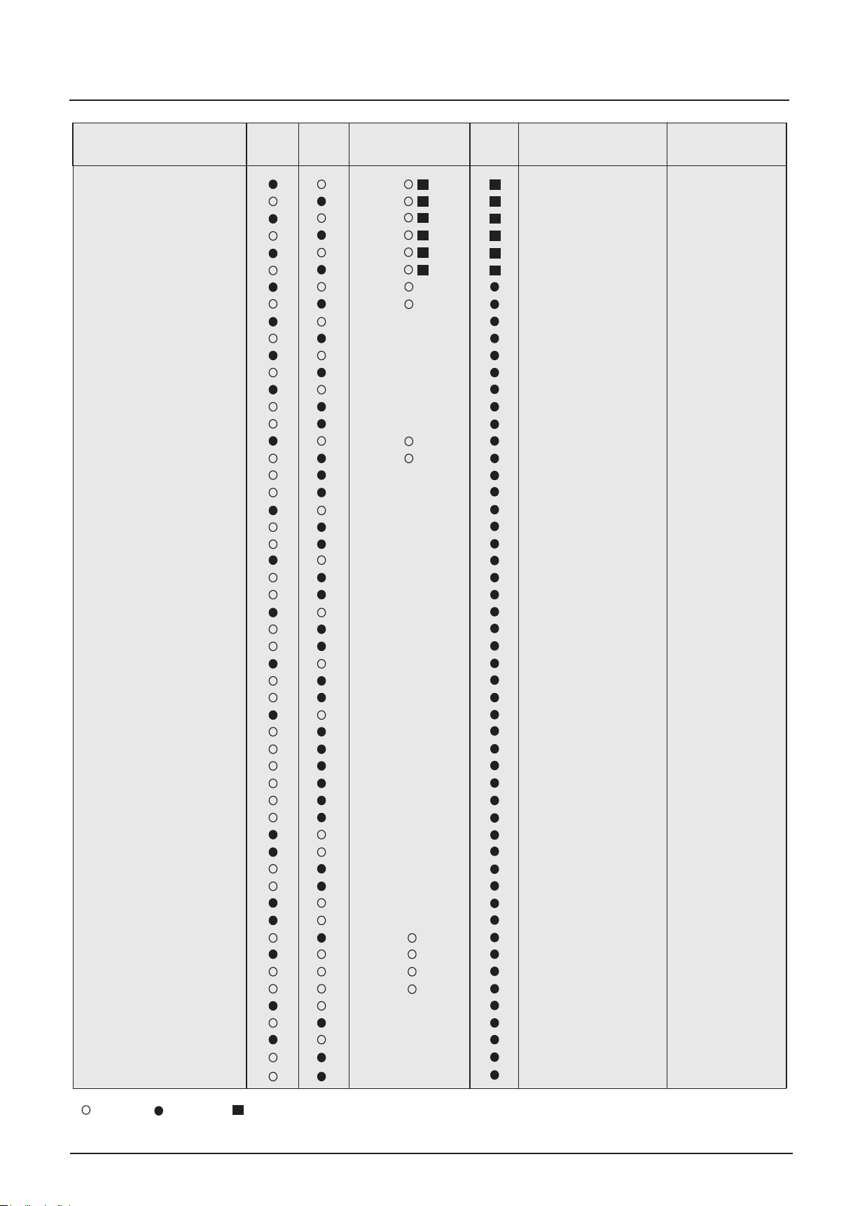
Instructions Manual
« S U P E R M A R K E T »
Co m merc i al Use Freezer
750 CHV/V
750 CHV/V R
900 CHV/V
900 CHV/V R
1100 CHV/V
1100 CHV/VR
SUPER
SUPER R
SUPER D
SUPER D R
SUPER DE
SUPER D RE
SUPER DPN
SUPER DPN R
SUPER DPNR E
PANORAMICA 2
PANORAMICA 2 R
PANORAMICA 2D R
PANORAMICA 2 D RE
PANORAMICA 2 DPN
PANORAMICA 2 DPN R
PANORAMICA DPN RE
SUPER TOPO D
SUPER TOPO D R
SUPER TOPO D RE
SUPER TOPO DPN
SUPER TOPO DPN R
SUPER TOPO DPN RE
PANORAMICA TOPO
PANORAMICA TOPO DR
PANORAMICA TOPO D RE
PANORAMICA TOPO DPN
PANORAMICA TOPO DPN R
PANORAMICA TOPO DPN RE
DUPLA D R
DUPLA DRE
DUPLA DPN R
DUPLA DPN RE
CEP 2 D
CEP 2 DPN
CEP 2 D R
CEP 2 DPN R
CEP 1.5 D
CEP 1.5 DPN
CEP 2
CEP 2 R
CEP 1.5
CEP 1.5 R
CEP TOPO D
CEP TOPO D R
CEP TOPO DPN
CEP TOPO DPN R
ARV 2.5 DE
R134 a R290
DEFROSTING LED DIMENSIONS (mm)
semi-automac
semi-automac
automac
automac
semi-automac
semi-automac
automac
semi-automac
automac
semi-automac
semi-automac
automac
semi-automac
semi-automac
automac
semi-automac
semi-automac
automac
semi-automac
semi-automac
automac
semi-automac
semi-automac
automac
semi-automac
automac
semi-automac
automac
semi-automac
semi-automac
semi-automac
semi-automac
semi-automac
semi-automac
semi-automac
semi-automac
semi-automac
semi-automac
automac
OPERATION
Freezing
Freezing
Freezing
Freezing
Freezing
Freezing
Freezing
Freezing
Freezing
Freezing
Freezing
Freezing
Freezing/Cooling
Freezing/Cooling
Freezing/Cooling
Freezing
Freezing
Freezing
Freezing
Freezing/Cooling
Freezing/Cooling
Freezing/Cooling
Freezing
Freezing
Freezing
Freezing/Cooling
Freezing/Cooling
Freezing/Cooling
Freezing/Cooling
Freezing
Freezing
Freezing/Cooling
Freezing/Cooling
Freezing/Cooling
Freezing
Freezing
Freezing/Cooling
Freezing/Cooling
Freezing
Freezing/Cooling
Freezing
Freezing/Cooling
Freezing
Freezing/Cooling
Freezing
Freezing
Freezing
Freezing
Freezing
Freezing
Freezing/Cooling
Freezing/Cooling
Freezing
1550 x 960 x 780
1550 x 960 x 780
2050 x 960 x 780
2050 x 960 x 780
2050 x 960 x 780
2500 x 960 x 780
SUPER 1.5:
1520 x 920x 790
SUPER 2:
2020 x 920 x 790
SUPER 2.5:
2500 x 920 x 790
2020 x 920 x 830
2020 x 920 x 830
2020 x 920 x 830
2020 x 920 x 830
2020 x 920 x 830
2020 x 920 x 830
2020 x 920 x 830
2020 x 920 x 830
2020 x 920 x 830
1990 x 920 x 790
1990 x 920 x 790
1990 x 920 x 790
1990 x 920 x 790
1990 x 920 x 790
1990 x 920 x 790
1965 x 920 x 830
1965 x 920 x 830
1965 x 920 x 830
1965 x 920 x 830
1965 x 920 x 830
1965 x 920 x 830
2150 x 1465 x 930
2150 x 1465 x 930
2150 x 1465 x 930
2150 x 1465 x 930
2000 x 880 x 940
2000 x 880 x 940
2000 x 880 x 940
2000 x 880 x 940
1500 x 880 x 940
1500 x 880 x 940
1500 x 880 x 940
2000 x 880 x 940
1500 x 880 x 940
1500 x 880 x 940
1770 x 840 x 900
1770 x 840 x 900
1770 x 840 x 900
1770 x 840 x 900
2505 x 1005 x 670
V2020_04
No
Yes Optional
Page 4
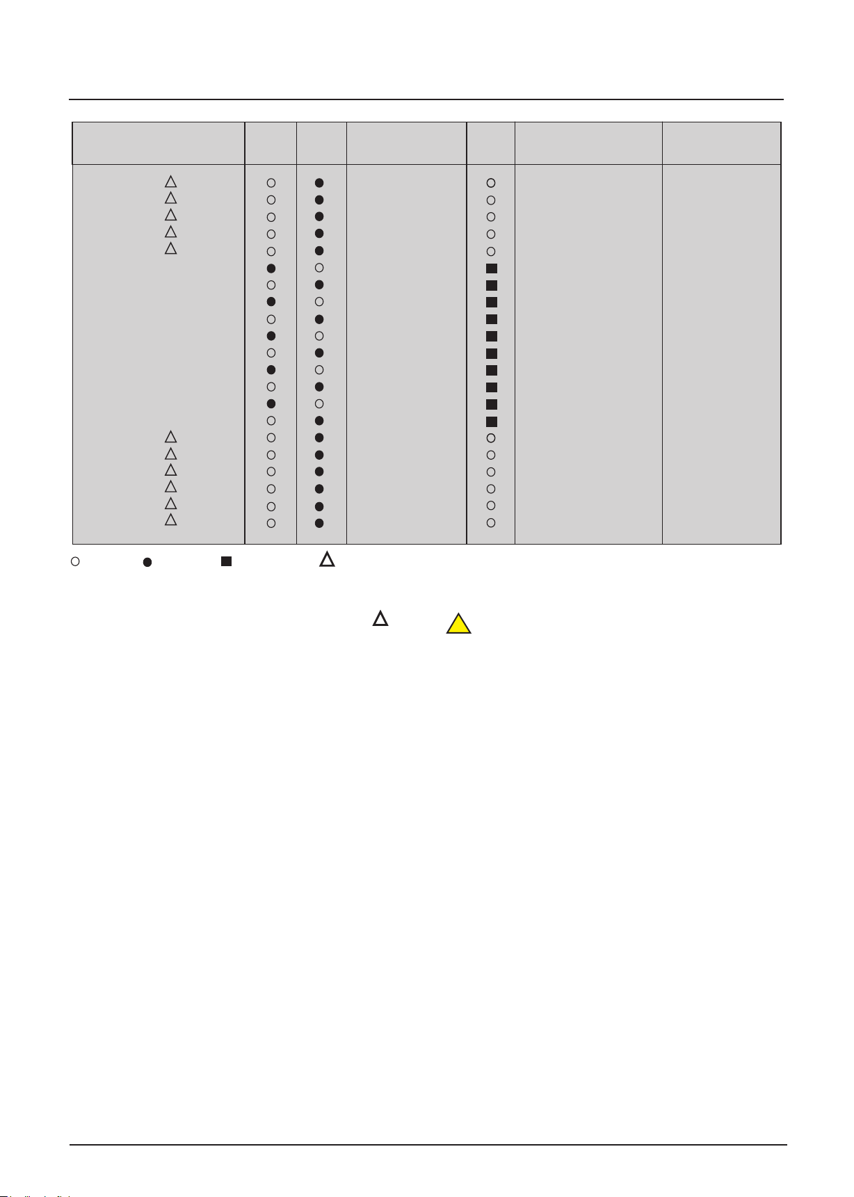
Instructions Manual
«HORECA»
Commercial/Home Use
210 CHV R
320 CHV R
430 CHV R
550 CHV R
700 CHV R
210 CHV/V
210 CHV/V R
320 CHV/V
320 CHV/ V R
430 CHV/V
430 CHV/V R
550 CHV/V
550 CHV/V R
700 CHV/V
700 CHV/V R
320 CHV/TC R
430 CHV/TC R
550 CHV/TC R
ALFA 1100 R
ALFA 1400 R
ALFA 1800 R
R134 a R290
TYPE OF LIDS
Liing Opaque
Liing Opaque
Liing Opaque
Liing Opaque
Liing Opaque
Sliding - Glass
Sliding - Glass
Sliding - Glass
Sliding - Glass
Sliding - Glass
Sliding - Glass
Sliding - Glass
Sliding - Glass
Sliding - Glass
Sliding - Glass
Sliding - Opaque
Sliding - Opaque
Sliding - Opaque
Sliding - Opaque
Sliding - Opaque
Sliding - Opaque
LED DIMENSIONS (mm)
OPERATION
Freezing
Freezing
Freezing
Freezing
Freezing
Freezing
Freezing
Freezing
Freezing
Freezing
Freezing
Freezing
Freezing
Freezing
Freezing
Freezing
Freezing
Freezing
Cooling
Cooling
Cooling
800 x 600 x 870
1110 x 600 x 870
1410 x 600 x 870
1810 x 600 x 870
1910 x 700 x 870
800 x 600 x 820
800 x 600 x 820
1110 x 600 x 820
1110 x 600 x 820
1410 x 600 x 820
1410 x 600 x 820
1810 x 600 x 820
1810 x 600 x 820
1910 x 700 x 820
1910 x 700 x 820
1110 x 600 x 820
1410 x 600 x 820
1810 x 600 x 820
1110 x 600 x 820
1410 x 600 x 820
1810 x 600 x 820
Não
Sim Opcional
Home Use
The appliances marked with the symbol in
the table above are considered under the
specific household appliances standard. These
appliances must be used in household and
similar applicaons, such as:
- Kitchen areas reserved for staff of shops,
workshops and other professional
environments.
- Coages and for use by the clients of hotels,
motels, holiday homes and other residenal
and typical household environments.
- Hotel room type environments.
- catering and other similar applicaons,
except retail.
WARNING! These appliances can be used
!
by children from 8 years of age or older and
by people with reduced physical, sensory or
mental abilies, or lack of experience and
knowledge if they are supervised or have
received instrucons on how to use the
devices in a safe way, and they understand
the risks involved.
- children must not play with the appliance.
- children aged from 3 to 8 years can charge
and disconnect the chilling appliance.
V2020_04
Page 5
Instructions Manual
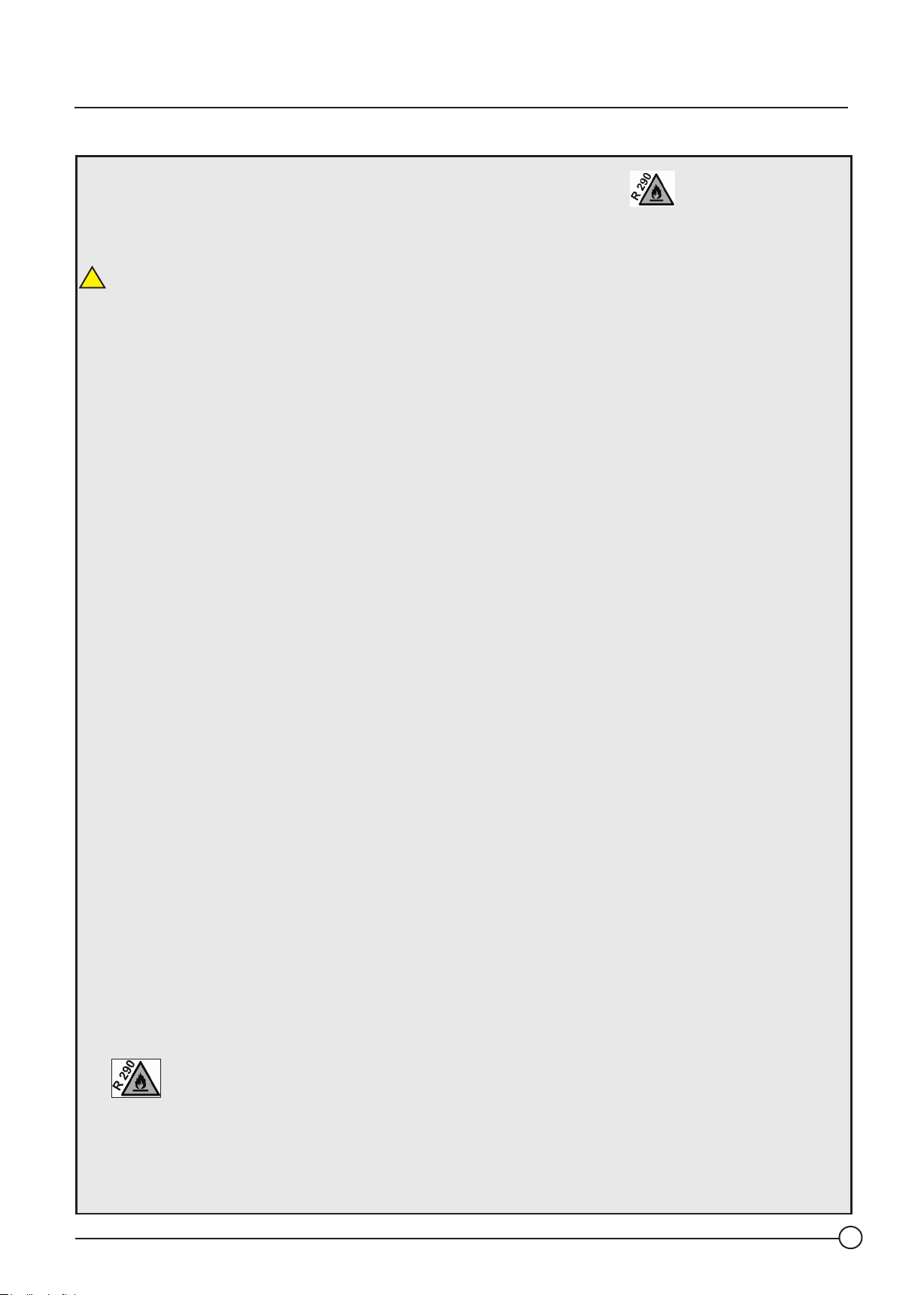
Warnings for appliances with cooling agent R290 General Warnings
IMPORTANT!
Appliances with the «R» designaon on the model, and the symbol on the data plate,
means that the cooling gas used in the cooling system is PROPANE - R290 and highly
inflammable.
!
ATTENTION! Electrical and/or cooling system installaon may only be carried out by duly
qualified people. In the event of failure to meet this condion, the manufacturer will not be
held liable for any problems caused, as well as any right to claim under the warranty.
The cooling fluid R290 (CH3CH2CH3) (propane) is classified in accordance with standard EN3781, in the group of inflammable and explosive refrigerants, with a GWP=3 (Global Warming
Potenal) and ODP=0 (Ozone Depleon Potenal).
R290 is a natural gas and harmless to the environment, however it always requires some
precauons due to its inflammability:
1- Your freezer owes, in part, its proper funconing to the forced venlaon with which it is
equipped. However, air circulaon obstrucon, located in the front, rear and/or side can
compromise the efficiency and safety of your appliance.
2- To install the appliance, an essenal condion for its proper funconing and safety is a
well-venlated and spacious locaon, where air circulaon is never restricted.
3- The work undertaken should only be carried out by specialised technicians with
appropriate training.
4- Do not use mechanical and/or electrical devices to speed up the defrosng process.
Remove the ice with the scrapper that is provided with the instrucons manual, so as to avoid
damaging the cooling circuit.
5- Do not use electrical equipment inside your appliance.
6- When carrying out repairs, whenever you have to open the cooling circuit, make sure that
it is opened in a well-venlated locaon or outdoors. Any repairs must only begin aer ensuring
that there is no gas in the circuit.
7- If any electrical system is used, whether for maintenance and/or repairs, it must be in
conformity with the ATEX direcve and comply with the minimum safety requirements for use in
potenally explosive atmospheres.
8- No explosive substances such as aerosols containing flammable propellants must be kept
inside this appliance.
Fire Risk / Flammable Materials
V2020_04
1
Page 6
Instructions Manual
General Warnings
To avoid the risk of accidents and
damage to the appliance, please read
these instructions before installation
and before using it for the first time.
They contain important notes on the
safety, operation and care of your
appliance. Keep these instructions in a
safe place for future use!
Informação! Emission sound pressure
level is bellow 70 dB
SAFETY INDICATIONS / WARNINGS
ATTENTION! Do not store explosive
!
substances such as aerosols containing
flammable propellants in this appliance.
VERY IMPORTANT:
Whenever you wish to clean the outer
casing of your appliance, never do it
directly with water. Water or humidity in
the electrical circuit can seriously damage
Before connecting the appliance, make
sure that the connection data (voltage and
frequency) on the data plate match the
local mains electricity supply.
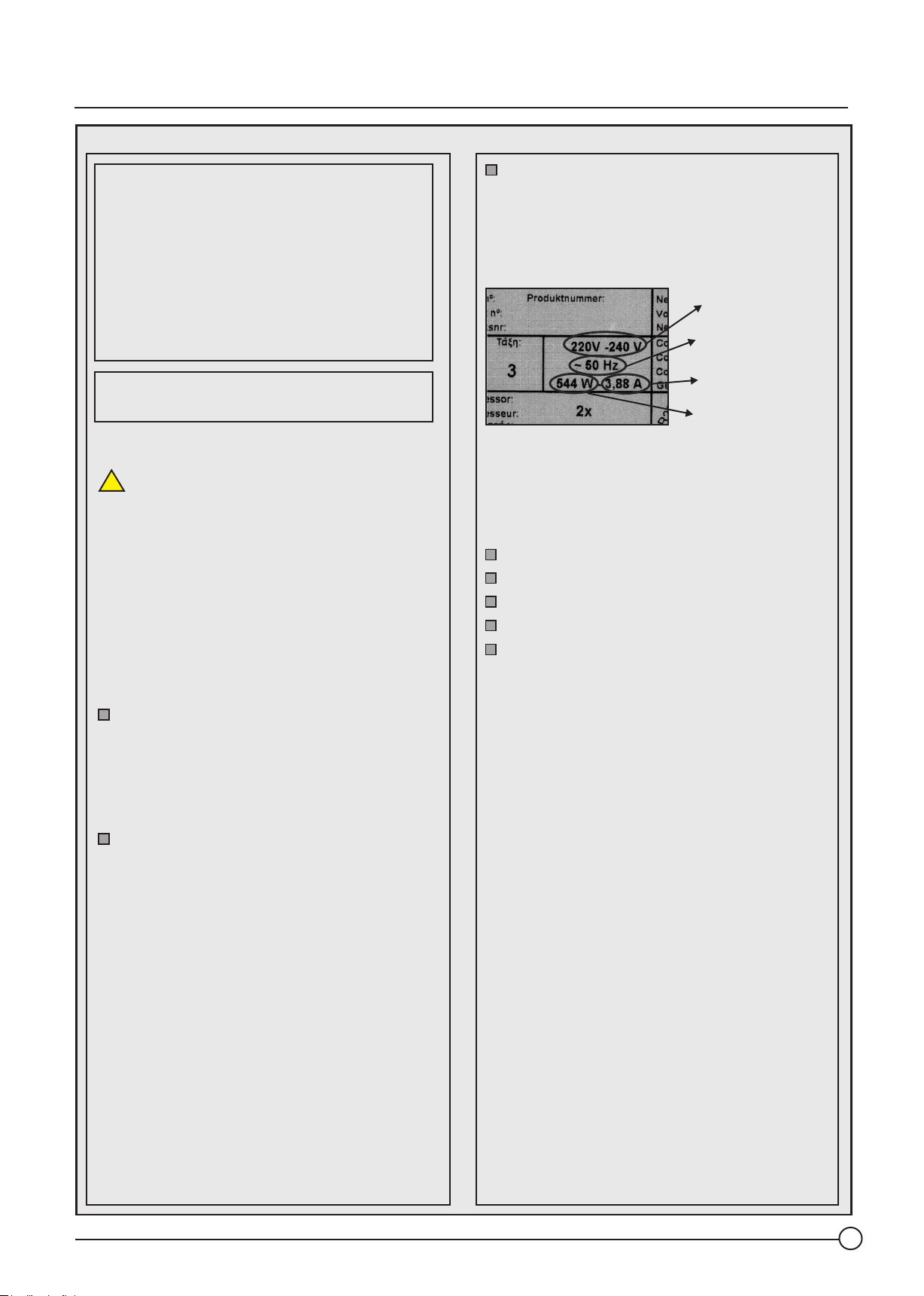
(see example of Fig. 1)
Nominal Voltage
Electrical
Frequency
Nominal Current
Nominal Power
Figure 1
The data plate is posioned at the rear of
the appliance which contains more
important technical data, such as:
Appliance model
Serial number
Climate class
Type of coolant used and quanty
Name and address of the manufacturer
or authorized representave.
When cleaning the floor, be careful not
to splash water on or in the vicinity of the
appliance. Observance of this rule may
avoid the risk of serious damage to the
appliance.
Do not use mechanical devices or
other devices to speed up the defrosting
process. Remove the ice as recommended,
so as to avoid damaging the cooling circuit.
See explanation in
the Maintenance/Cleaning chapter.
VERY IMPORTANT: The plastics
of the appliances must not be cleaned with
cleaning products that contain ammonia or
solvents. Always use neutral soap based
products.
In addion, at the front of the appliance
next to the frame there is a small scker
that indicates the model of the appliance.
V2020_04
2
Page 7
Instructions Manual
General Warnings
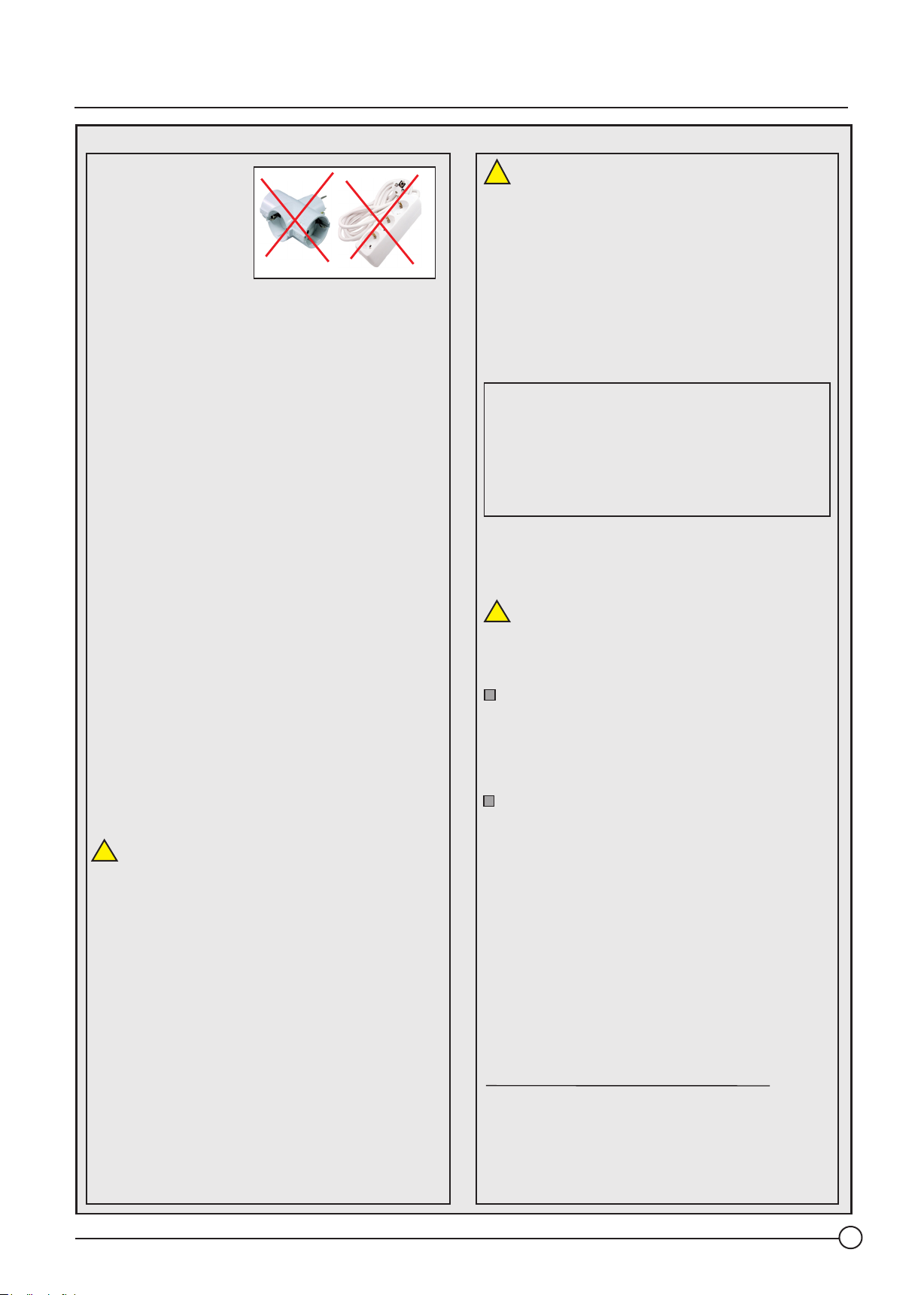
WARNING! Do not
use multiple
portable plugs or
portable power
supplies at the back
of the appliance.
These do not guarantee the required safety
of the appliance (e.g. danger of
overheating).
Do not expose this ATTENTION!
!
appliance to direct sunlight.
According to its climate class, do not install
the appliance in environments where the
temperature/humidity does not correspond
to the class indicated on the data plate. See
point 1.2 on the following page.
Wood Storage/Packaging
NOTE! Your appliance is only disconnected
from the electricity supply when the
connection plug is disconnected from the
wall socket.
Before undertaking any maintenance or
repair work, remove the plug from the
electrical socket.
VERY IMPORTANT: The appliance must be
posioned in such a way as to ensure quick
and easy access to the socket and when the
plug is removed it must be placed in such a
way that the operator can check, from any
of the points to which he/she has access,
that the plug is sll removed.
WARNING! When positioning the
appliance, make sure that the power cord is
not trapped or damaged.
ATTENTION! The electrical safety of this
!
appliance can only be guaranteed when it is
correctly earthed and has its own current
circuit.
VERY IMPORTANT:
Any servicing, including the replacement of
lighting, or replacement of the power cable
must be performed by the after-sales
service in order to prevent danger.
The equipment was inspected at the time
of packaging at the factory. Any claim of
damage must be made to the transport
company. The transport company will
provide all the necessary documents.
Receiving and Inspection of Equipment
(Transport/Packaging)
WARNING!
!
All equipment shall be inspected visually
before and during unloading.
To prevent damage during handling or
transportation, do not remove the
packaging from the equipment until it
reaches the final place of installation.
To maintain the quality assurance of the
products in the packaging, avoid their
exposure to high temperatures and/or
direct sunlight. Refer to item 1.2 on the
next page
Place the pallet on a levelled and firm
surface. Inspect the equipment for visible
VERY IMPORTANT:
The device must always be moved, used
and/or transported in a horizontal
posion.
V2020_04
Manufacturer's name and address:
ARCABOA - Industria de frio, s.a.
R. Do Lordelo
4510 - 591 - Fânzeres.
PORTUGAL
3
Page 8
Instructions Manual
1- INSTRUCTIONS FOR INSTALLATION AND USE:
1.1 - INSTALLATION OF YOUR APPLIANCE
When installing the appliance, the following precautions must
be taken:
The pavement should be completely level, so as to permit
the feet to be laid firmly flat.
A key condition for the proper operation of the appliance
is that it be placed in a well-ventilated room and not exposed
to direct sunlight or any other source of heat. Figure 2
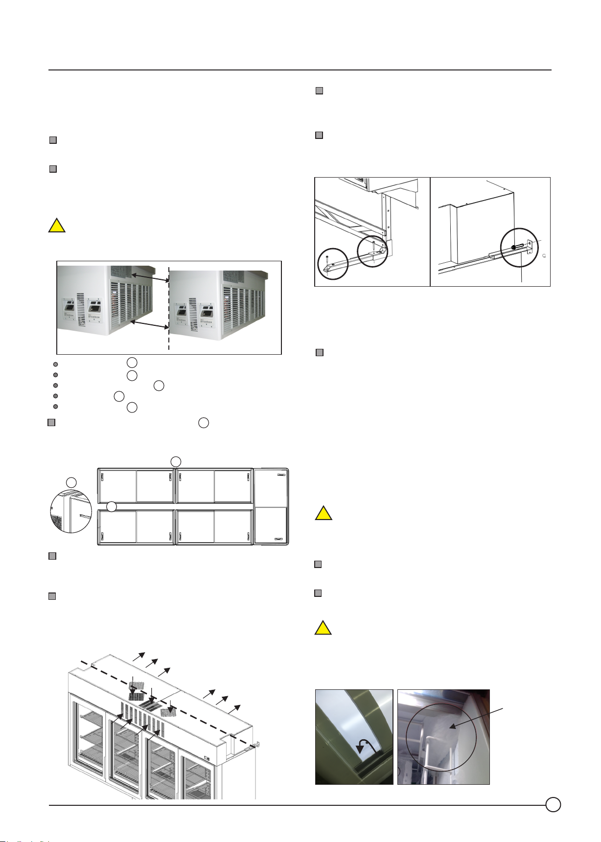
indicates the distance between appliances in a plug-in joint.
ATTENTION! In an individual installation, the distance
!
between the appliances and the nearest walls or furniture/
shelves must be at least 150 mm.
Min. (A) mm
Model CHV/V : = 50 mm
Model SUPER : = 20 mm
Model PANORAMICA: = 20 mm
Model CEP: = 50 mm
Model DUPLA: = 20 mm
The gaps in the corridor where two appliances are
joined cannot be covered up, unless special bore grilles
supplied by the manufacturer are used.
B
A
A
A
A
A
B
A
B
Figure 2
In a PLUG-IN installation of several appliances, always
comply with the configuration indicated by
the manufacturer.
The appliance you have purchased partly owes its good
functioning to the forced ventilation it is equipped with.
However, obstructing the air flow around the rear, side or top
grille (mod. ARV ) depending on the model, may reduce the
normal efficiency of your appliance.
IN
Do not place thick advertising boards on the outer casing.
The boards can only be placed on thin film and so as to never
cover up the air inlets of the appliance.
Avoid air currents and heat radiation in the room where
the appliance is installed. Any heat radiation in the vicinity of
the appliance will lower its energy efficiency and raise
energy costs.
support structure fixing brackets
VERY IMPORTANT!
The support structure of the vertical cabinet (model ARV)
must be attached to the floor and the side fixing brackets
must be attached to the wall.
The appliance that you purchased owes, in part, its
proper functioning to the forced ventilation with which it is
equipped. However, obstruction of air circulation, through
the rear or side grille, depending on the model, can
undermine the normal efficiency of your appliance.
1.2- OPERATING AND STORAGE TEMPERATURE
The ambient room temperature where the appliance is
going to be installed must not exceed 32ºC or drop below
16ºC.
The temperature in the warehouse or during transport
must not exceed 55ºC. Danger of deformation of plastics.
NOTE! To guarantee the temperature at load limit the
!
appliance must be installed in a room according to its range.
This information is indicated in the data plate of the
appliance, example;
CLASS 3L1: Maximum ambient room temperature of
+25ºC / Relave Humidity less/equal to 60%
CLASS 4L1: Maximum ambient room temperature of
+30ºC / Relave Humidity less/equal to 55%
NOTE! If the % relative humidity values are equal to
!
60 +/- 5%, condensation may appear on the glass covers.
In these situations, we recommend leaving the low
consumption LED lighting on at all times or regularly
cleaning the covers with absorbent paper.
V2020_04
OUT
Interior Ice
Formaon
4
Page 9
Instructions Manual
VERY IMPORTANT!
Always remove the condensation water accumulated on
the glass covers. Otherwise the water from condensation
will settle in the plastic profile where the cover fits and ice
will accumulate over time in the front corners of your
2- USE
The appliance which you purchased is designed to store
previously frozen and/or chilled food products depending
on the appliance model that you purchased. The
differences between the models are:
model : Freezing
model + D : Freezing
Automatic Defrosting
model + PN: Freezing
Cooling
model + DE: Freezing
Automatic Defrosting with Water
Evaporation (Diagram fig.4 / fig. 4.1)
2.1 - PLACIE THE PRODUCTS
Before placing frozen food in the appliance, you must:
Clean the interior with a damp cloth to remove any dust
that might exists. Then wipe with a dry cloth.
Connect the appliance to the wall socket.
Place the plug into the socket and wait until the appliance
starts automatically.
Let the appliance operate on empty for about 4 hours.
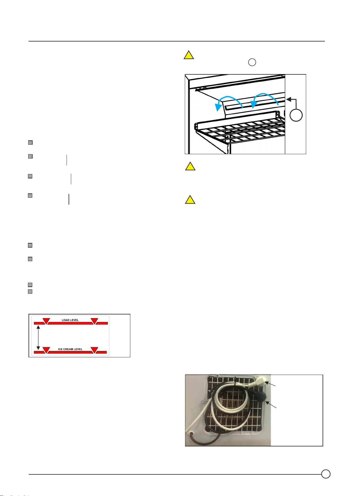
After addressing these three points, place the products
below the load level indicator, engraved on the inner wall of
your appliance.
PLEASE NOTE! In the ARV model never place products
!
on the air ventilation slots represented in the figure
A
below.
A
NOTE! As an exhibition booth, these appliances are
!
not intended for freezing fresh products.
2.2 - ELECTRICAL CONNECTION
ATTENTION! The electrical safety of this appliance can
!
only be guaranteed when it is correctly earthed, and it has
an independent connection circuit and protection according
to the standardisation of each country.
VERY IMPORTANT: This basic safety condition must be
observed and, if there are any doubts, the electrical
installation must be checked by a certified electrician.
The Manufacturer cannot be held liable for malfunction or
damage due to the lack or interruption of the earth
connection.
As mentioned in page 2, the appliance should only be
connected if it complies with all the safety rules.
2.2.1 - CONNECTION OF LED LIGHTING VIA EXTRA CABLE
(OPTIONAL)
+/- 65 mm
Figura 3
VERY IMPORTANT! Above this level (Load Level - Fig. 3), an
acceptable minimum temperature in frozen products is no
longer guaranteed.
V2020_04
The appliance, in its standard version, is equipped with a
green interrupter, to switch on and off the interior lighting
(example in the figure of point 4.3).
As an option, there is the possibility of using the extra
power cable supplied to control the interior lighting, (black
electrical cable with a grey sticker marked - LED LIGHTING -)
bearing in mind the electrical connection and protection
circuit.
CONNECTION PLUG
LED CONNECTION
PLUG (OPCIONAL)
5
Page 10
Instructions Manual
ATTENTION! The extra power cable should be
!
connected to an additional socket, independent from the
socket circuit of the freezer. The protection should be
adjusted to the power of the lighting circuit.
4. CONTROL PANEL - TEMPERATURE SETTING -
The control panel is located in the front part of your
appliance. The appliance can be equipped with a
mechanical thermostat or an electronic controller.
VERY IMPORTANT: Certify that the appliance is not
connected to the lightning circuit.
2.2.2. DATA CABLE
As an option, the appliance can be pre-installed with a
communication card and connector for an RS485
connection outlet through a Belden cable.
This system is only applicable to appliances equipped with
the DANFOSS AK-CC 210 A controller and the DIXELL XR 77
CX model.
3. INSTALLATION AND COMMISSIONING
ATTENTION! Before putting your appliance into
!
operation, read point 2 of the previous page carefully.
Connect the plug to the electrical socket and wait.
The appliances equipped with electronic controller have a
factory -defined time to start.
4.1. APPLIANCES WITH A MECHANICAL THERMOSTAT
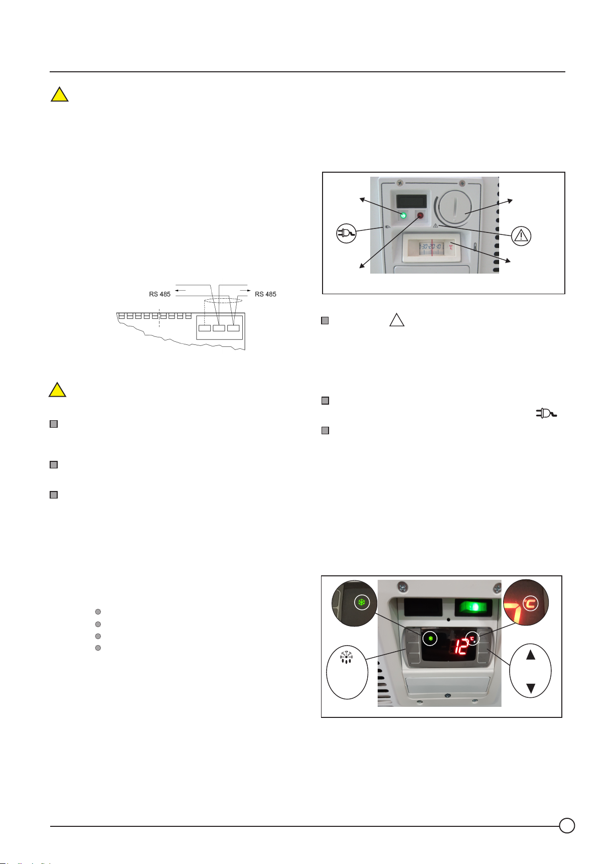
Green
indicator
Red
indicator
Red indicator whose function is simply to inform if the
interior temperature of the freezer rises above dangerous
values for the stored products
NOTE! In the cooling devices (ALFA model), the red indicator
is replaced by an orange indicator. This indicates that the
appliance is cooling.
Green indicator whose whose function is to inform if the
appliance is connected to the mains electricity supply .
Thermometer indicating the temperature in the interior
of the freezer.
!
Thermostat
Analogue
Thermometer
Let the appliance operate for 4 hours, without placing
any frozen food in the freezer.
At the end of 4 hours, place the frozen or chilled goods
(DPN model) in the appliance, always below the load level.
VERY IMPORTANT: Respect the storage temperature
according to the type of product
Examples of storage temperatures according to the range
of the L1 (refrigeration -15/-18) or M1 (cooling +5/-1)
appliance - the type of range is to be confirmed on the data
plate.
Some reference values are shown below:
Frozen: -15 ºC to -18 ºC
Ice-cream: -20 ºC to -22 ºC
Meat: -1ºC +2 ºC
Fruit / Vegetables: +6 ºC to +12 ºC
4.2 APPLIANCES WITH ELECTRONIC TEMPERATURE
CONTROL - DIXELL MODEL
The appliance can be equipped with 2 different DIXELL
controller models. The XR02CX model, used in appliances
without defrosting, while the XR 77 CX model equips the
appliances with automatic defrosting in the D, DPN, D E and
DPN E models.
Its main functions are explained below.
2
1
SET
2
XR02CX
V2020_04
6
Page 11
Instructions Manual
2
2
SET
XR77CX or XRi 77CX
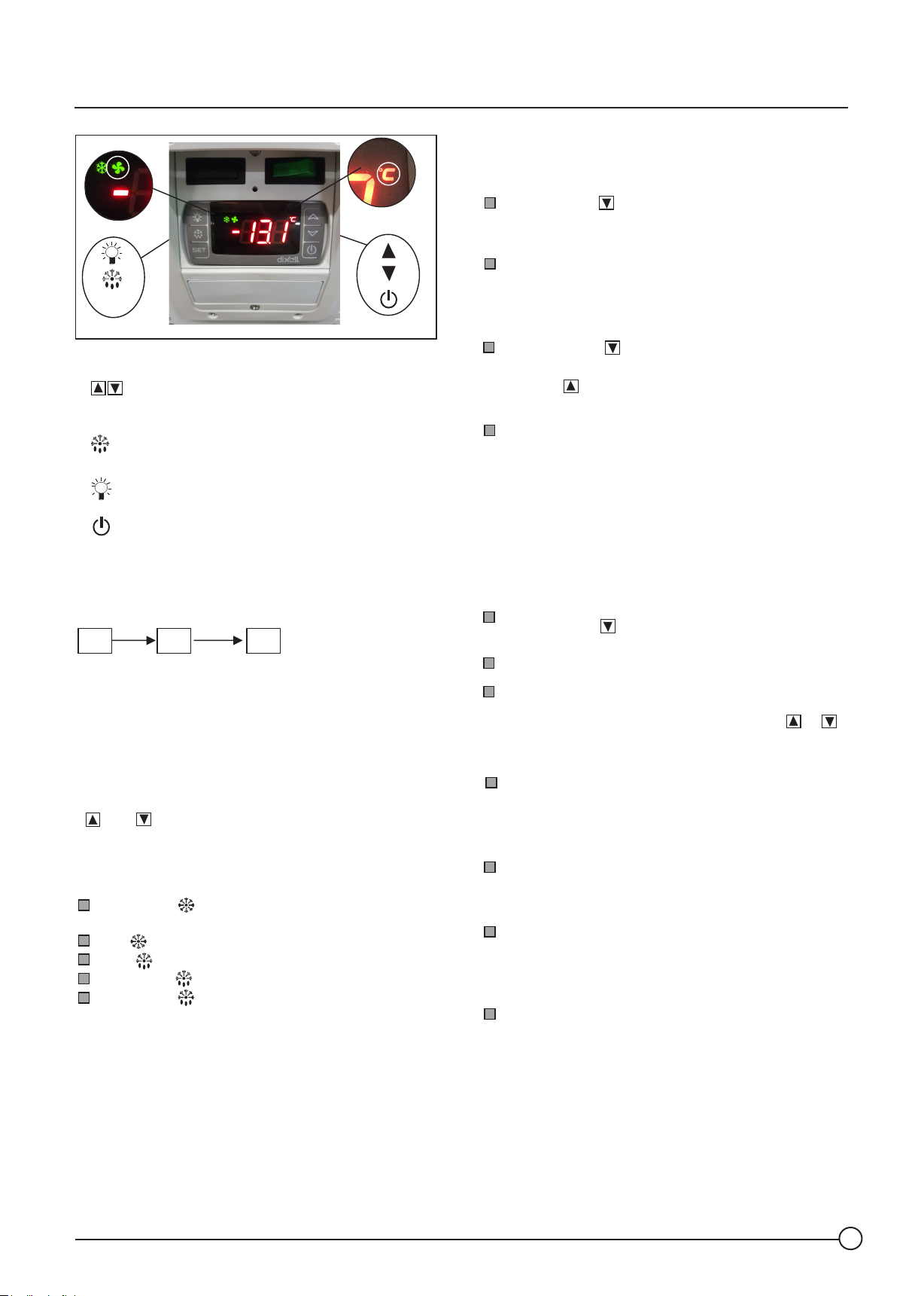
4.2.1 DEFINITION OF THE KEYS
key : Increase/Decrease the Setpoint value.
key : View and change the Setpoint value
SET
key : Initiate manual defrosting cycle - Press for 3
seconds (only for XR77 controller)
4.2.3. CHANGE OF UNIT OF MEASURE
The preset unit of measure of the electronic temperature
controller is ºC. If you wish to change to ºF, proceed as follows:
Press the SET + keys for approximately 3 seconds, until
the «Hy» parameter appears on the XR 02 controller and RTC
on the 77CX model.
Press the same keys simultaneously again for
approximately 8 seconds this time, until the L2 code
appears on the XR02CX model and Pr2 on the XR77CX
model - access to the general menu of the controller
Click on the key until you find the «CF» parameter and
then on SET to enter the parameter.
With the key select ºF (fahrenheit) and click on SET again to
save the change.
Lastly, wait until the controller exits the programming
mode and returns to the temperature value.
key : Turn the interior lighting On and Off.
(ARV 2.5 DE models only).
key : Turn the controller On and Off.
Option not activated. Contact supplier to activate this
option.
IMPORTANT! The appliance is factory-programmed for
automatic lighting. Operating hours according to diagram.
9h 21h 9h
LED on
4.2.2. TEMPERATURE SETTING
To change the operating temperature of your appliance, press
the SET key until the indicator «ºC» (represented in the figure
above with the number 2) begins flashing. At this moment you
can change the average interior temperature of your
appliance by increasing or decreasing the values using the
and keys.
When the new value has been set, click again on the SET key,
the «ºC» led will be set and the new value is memorised.
Information (1)
intermittent green LED: means pre-defined minimum
waiting time for start up of the compressor.
fixed green LED: means appliance is generating cooling.
fixed yellow LED: defrosting.
intermittent yellow LED: in pump down
intermittent yellow LED : Pre-heating the evaporation
recipient.
LED off
4.2.4 REAL TIME CLOCK SETTING
As already previously mentioned, the controller that equips
the appliances, with automatic defrosting (D and DPN) (DE
and DE PN) already contains a preset real time clock (RTC).
(Only applicable to the XR77CX controller). Nonetheless, the
parameters to adjust the clock are indicated below if
necessary:
Press the SET + keys for approximately 3 seconds,
until the «RTC» parameter appears.
Click on SET to enter the real time clock menu.
Then and after the Hur parameter has appeared, click on
SET and define the value of the hour through the or
keys and click again on SET to go on to the adjustment of
the value of the minutes and day of the week.
Lastly, wait until the controller exits the programming
mode and returns to the temperature value.
4.2.5. ALARM INFORMATION
P1 and P2: Error in the temperature probe.
Cause: Malfunction of the probe, probe terminal
disconnected or not properly connected.
HA: Alarm Temperature.
Cause: Loss of refrigeration performance, replacement of
products with a high temperature, change of the SETPOINT
value, prolonged power outage or open lids.
RTC: Real time clock setting.
Cause: Appliance disconnected from the power supply
for more than 6 months. Discharge of the internal storage
battery.
V2020_04
7
Page 12
Instructions Manual
ATTENTION! As previously mentioned, defrosting is
!
factory preset in the XR77CX controller. If the appliance is
not put into operation in a period of less than 6 months,
you may have to set the time once again.
4.2.6. CHANGE TEMPERATURE RANGE OF APPLIANCE
In the DIXELL controller, to change the operating
temperature range (DPN or DE PN models), proceed as
mentioned in the previous section.
4.2.2 - TEMPERATURE SETTING.
The recommended SETPOINT value is 0 ºC
4.3 PANEL WITH ELECTRONIC TEMPERATURE CONTROLLER
- DANFOSS MODEL
The DANFOSS AK-CC 210-A electronic temperature
controller was specifically designed for our appliances.
The controller is also equipped with an automatic
defrosting system, used in the D, DPN, DE and DE PN
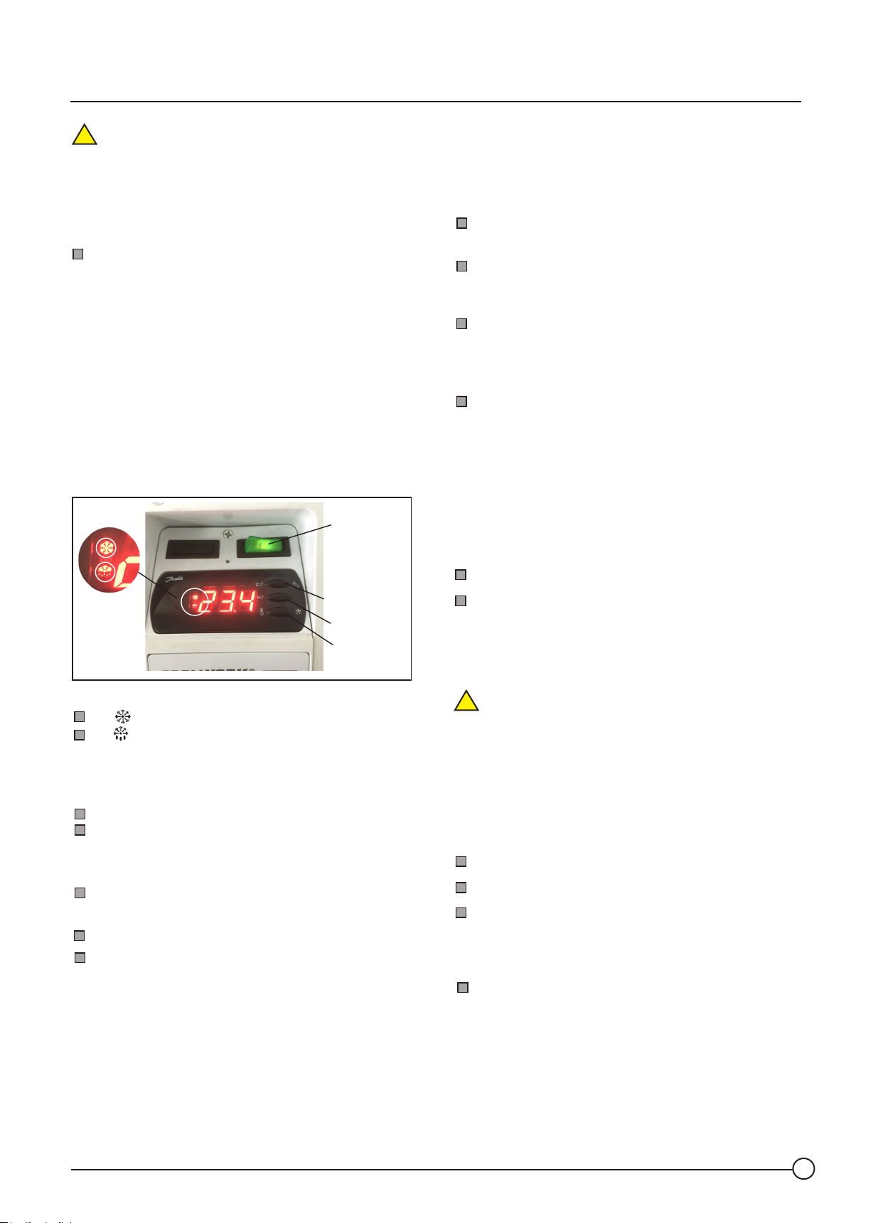
on/off LED
1
switch
2
4.3.3 CHANGE OF TEMPERATURE UNIT
The factory preset unit of measure of the electronic
temperature control is ºC. If you wish to change it to
ºF (fahrenheit), proceed as follows:
Press the upper key for 3 to 4 seconds until the word
- PS - (password) is shown in the display.
Press the upper key until you reach the value of 33 and
click on the central key. At this moment you have entered
the parameters of the controller.
Then click on the lower key until you find the r 05
parameter. Click on the central key and then select, with
the upper key, the ºF (fahrenheit) option and click on the
central key again to save the value.
Wait approximately 1 minute and the controller will exit
the programming mode automatically.
4.3.4. CHANGE TEMPERATURE RANGE OF APPLIANCE
All the DPN and DE PN model appliances have been preset
to work at different temperature ranges. The appliance is
predefined to operate as an ice-cream display freezer.
However, if you wish to use it as a cooler, there are two
options to change the temperature:
First option: similar to what was mentioned in point 4.3.2
upper key
central key
lower key
Information (1) and (2)
led : means appliance is generating cold.
led or -d- : means in defrosting cycle.
4.3.1 DEFINITION OF KEYS
Upper Key:
Increase the Setpoint value
Enter the Programming - Press and maintain for 3
seconds.
Central Key:
View and change the Setpoint value.
Lower Key:
Decrease the Setpoint value
Initiate manual defrosting - Press and maintain for 3
seconds.
4.3.2 CHANGE OF TEMPERATURE VALUES
Second option: change the programming settings.
As set out in point 4.3.3, enter the programming mode,
select the r39 parameter and change from OFF to ON. The
appliance will automatically change the operating status to
values between -1 and +5ºC - M1 Class
NOTE! This function is only available in DPN and DEPN
!
models.
4.3.5 INTERNAL RESET OF THE CONTROLLER / FACTORY
SETTINGS
If you have changed parameter values and need to
reprogramme the factory values, all you need to do is reset
the controller. To that end, proceed as follows:
Disconnect the appliance from the power socket.
Press the upper and lower keys simultaneously.
Switch the appliance on again, maintaining the upper
and lower keys pressed. The display will show the factory
abbreviation «FAC» (internal reset and original factory
values restored).
Lastly, wait until the controller exits the programming
mode and returns to the temperature value.
Click on the central key, to view the SETPOINT value, and
with the upper or lower key, define the temperature value
that you want.
At the end, click on the central key to save the new value.
V2020_04
4.3.6. REAL TIME CLOCK SETTING
As already previously mentioned, the controller that equips
the appliance is equipped with a real time clock.
Nonetheless, the clock (RTC) settings may be adjusted as
indicated below.
8
Page 13
Instructions Manual
If you wish to opt for defrosting at night ATTENTION!
!
time, (point 5.1) the clock must always be reset.
Press the upper key for 3 to 4 seconds until - PS (password) is shown on the display
Press the upper key until you reach the value of 33 and
click on the central key. At this moment you have entered
the parameters of the controller.
With the lower key, run through the various parameters
until you come to the t07 parameter. Click on the central
key to enter the parameter and define the hour.
Similarly, select the t08 parameter to define the minutes.
Example: local time 11:35 AM (t07= 11 and t08 = 35)
Lastly, wait until the controller exits the programming
mode and returns to the temperature value.
4.3.7. ALARM INFORMATION
When an information alarm is triggered on the controller, all
the LEDs of the display flash.
To obtain the error information, click once on the upper key
which will indicate the error code. Examples of the most
common errors are given below:
5. DEFROSTING
The accumulation of ice inside the appliance depends on 4
key factors:
1. Temperature / Relative Air Humidity
(values must not exceed the reference values
( +25ºC / 60 % - 3L1 class appliance)
2. Type of product placed in the interior.
3. Number of times that the lids are opened.
4. Lids not properly closed.
However, and depending on the 4 points mentioned above,
with the aid of a scrapper supplied with the manual, you
can scrape any layers of ice that remain, even in appliances
with automatic defrosting.
ATTENTION! Even in appliances with automatic (DE
!
model) and semi-automatic (D) defrosting, we recommend,
for hygiene reasons, a complete defrosting every six months
in the DE model and every three months in the D model
(see point 6.2)
IMPORTANT! We do not recommend the use of appliances
with defrosting to sell bulk products.
A1: High temperature alarm.
Cause: Loss of refrigeration performance, replacement
of products with a high temperature, change of the
SETPOINT value, prolonged power outage or open lids.
E25 or E26: Malfunction of the temperature probe.
Cause: Malfunction, probe terminal disconnected or not
properly connected.
E6: Clock (RTC) setting
Cause: Appliance disconnected from the power supply
for more than 1 hour. Discharge of the internal storage
battery.
A45: Appliance on STAND-BY
Cause: r12 parameter equal to zero Change to 1 to exit
the STAND-BY mode.
ATTENTION! As a final note, please be aware that the
!
temperature indicated on the display of the electronic
controller of the appliance is not directly related to the
temperature of the products. The temperature probe is
placed at the mid-point, fixed on the front wall.
IMPORTANT: Never change the SETPOINT values, without
consulting the after-sales service.
5.1. CLOCK SCHEDULED DEFROSTING
The controllers have a real time clock, which activates the
defrosting. To set the time of the defrosting period, follow
these steps:
5.1.1 DANFOSS AK-CC 210A CONTROLLER
Press the upper key for 3 to 4 seconds until the word
- PS - (password) is shown on the display.
Press the upper key until code 33 appears and then click
on the central key.
With the lower key, run through the various parameters
until you come to the t01 parameter. Click on the central
key to enter the parameter and with the upper key, define
the time you intend the defrosting to take place. Click on
the central key again to save the value and go on to another
parameter (t11) to adjust the minutes.
VERY IMPORTANT: If you opt to programme defrosting at
night time, you will always have to place the d03 and d18
parameters at zero
V2020_04
9
Page 14
Instructions Manual
5.1.2 DIXELL XR 77 CX CONTROLLER
Press the SET + keys for approximately 3 seconds, until
the «RTC» parameter appears.
Press the same keys again for approximately 10 seconds
until the «Pr2» parameter appears.
Click on the key until you find the parameter that
defines the «Ld1» defrosting time and then press SET to
enter the menu.
With the keys and define the time you wish
defrosting to take place and click on SET to save.
Lastly, wait for the controller to exit the programming
mode automatically.
The preset time defined for defrosting is always night time
and starts at 21:00 (Ld1 = 21.0)
5.2 MANUAL DEFROSTING
In appliances without defrosting, disconnect the appliance
from the power supply and let the appliance defrost
naturally.
Use the sewage drain to facilitate the outflow of water, after
the natural defrosting of the appliance. (see figure bellow)
ATTENTION! Do not use mechanical devices or other
!
means to speed up the defrosting process.
NOTE! In models without defrosting the appliance is not
equipped with wire protections and trays.
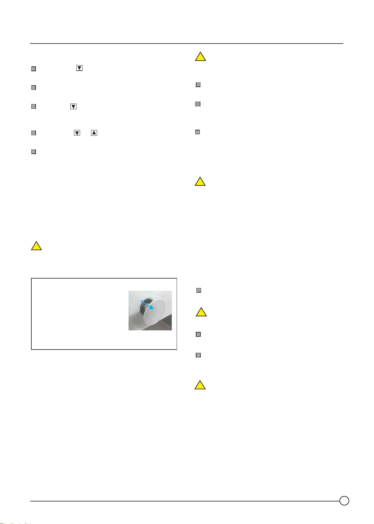
INFORMATION ON THE USE OF THE DRAIN
Use the drain that comes with your
appliance. Pull the lid on the left side
and in the front part of the appliance
outwards, as indicated in the figure.
Place a tray below the drain, to place the water
stemming from the defrosting of the ice.
ATTENTION! The appliances must not be cleaned with
!
cleaning products that contain ammonia or solvents.
Always use neutral soap based products.
Clean the outer casing regularly with a damp cloth.
Never clean it directly or indirectly with water.
When cleaning the floor, be careful not to splash water
on or in the vicinity of the appliance. Observance of this
rule may avoid the risk of serious damage to the appliance.
In the event of a change in the temperature range from
negative to positive values, in the DE PN model (automatic
defrosting), pay attention to the floor, next to the motors.
There may be an overflow of water from the evaporation
tray due to the formation of too much water on the walls of
the appliance. (point 6.2.2)
ATTENTION! The defrosted water, stemming from the
!
exit of the deposit can result in a slipping hazard. Clean the
floor immediately.
6.2 INTERIOR CLEANING
6.2.1 APPLIANCE WITH SEMI-AUTOMATIC DEFROSTING «D» MODEL
The appliance with semi-automatic defrosting is a less
efficient system, in which the water stemming from
defrosting is deposited at the bottom of the appliance.
The appliance should be cleaned every three months.
Prior to cleaning the appliance, proceed as follows:
Remove the lids of the appliance and place them in a
safe location.
ATTENTION! Always use gloves made of cloth so as to
!
avoid touching the inner surface of the glass directly with
your fingers.
Remove all the frozen food and store it in a cold
chamber or in another appliance for preservation.
An accumulation of ice on the walls means loss of efficiency
of the appliance.
Defrost and clean your appliance on a regular basis. Never
allow the layer of ice to exceed a thickness of 15 mm.
6. MAINTENANCE / CLEANING
The SUPERMARKET line appliances, with the exception of
the vertical cabinet (ARV model) do not require
maintenance, only cleaning. You should periodically create
a maintenance routine for the finned condenser on the
EUREKA line appliances and vertical cabinet (point 6.4)
6.1. EXTERIOR CLEANING
VERY IMPORTANT! Whenever you wish to clean the
outer casing of your appliance, never do it directly
with water
V2020_04
To simplify the cleaning and removal of ice from the
walls, always use manual defrosng in the D and DE models.
Acvate the manual defrosng of the appliance.
WARNING! The vertical cabinet, model ARV 2.5 DE, is a
!
ventilated cold appliance. In this case there is no frost build
up, except in the internal evaporator.
Do not use manual defrosting. Simply remove the mains
plug from the socket when you want to clean its interior.
10
Page 15
Instructions Manual
MANUAL DEFROSTING ACTIVATION WITH DANFOSS AK/CC
210 A CONTROLLER
Press the lower key of the controller for 5 seconds.
NOTE! At the end of the previous operation, check if the
display shows the letter -d- at the end of 30 seconds. If this
does not happen, repeat the operation.
MANUAL DEFROSTING ACTIVATION WITH DIXELL XR 77 CX
CONTROLLER
Press the key of the controller for 5 seconds, until the
yellow LED starts to flash, symbol of defrosting.
After defrosting has begun, await approximately 30
minutes. At the end of that time, disconnect the appliance
from the power supply or use the controller to place the
appliance on STAND-BY.
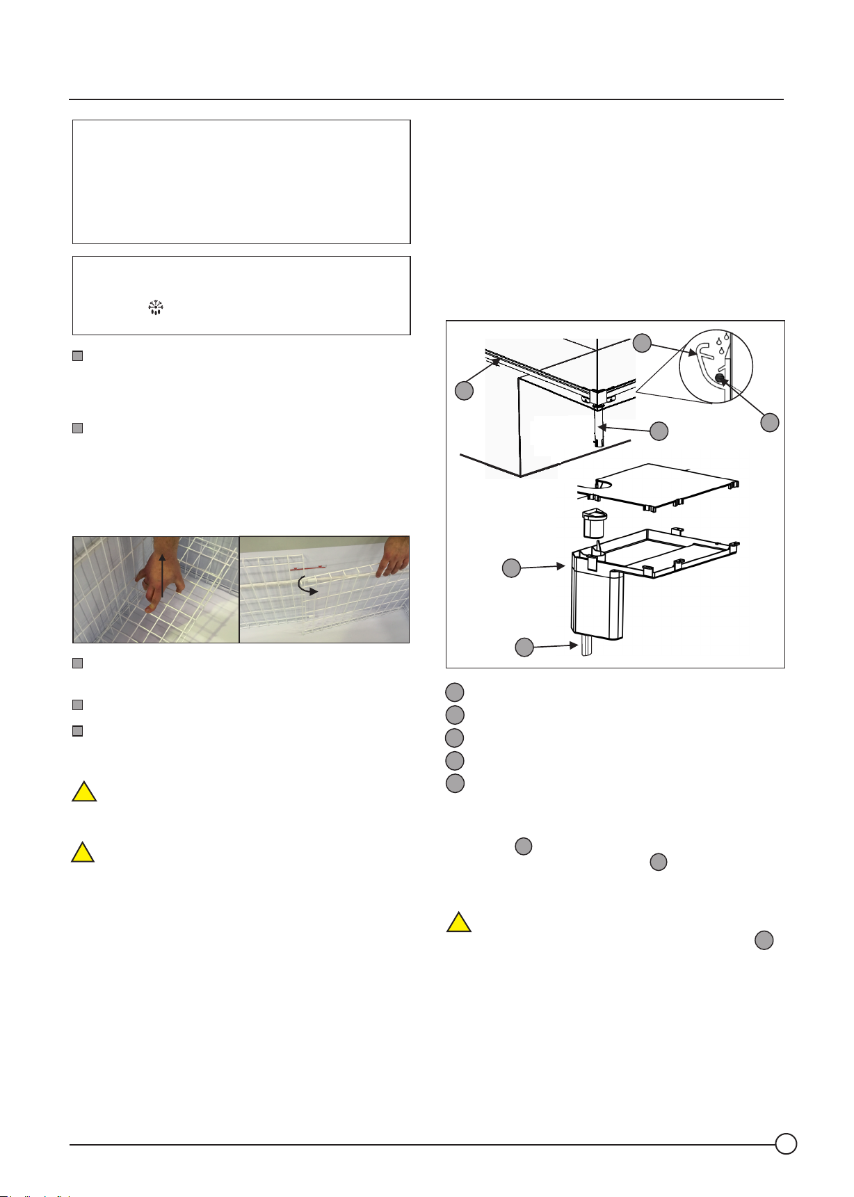
Remove the protection grilles, as shown in the figure
below, dragging with them some of the ice that has formed.
INFORMATION! Only the appliances with automatic
defrosting are equipped with grilles and trays. To facilitate
removal, always remove the trays first and only then the
wall protections.
6.2.2 APPLIANCE WITH AUTOMATIC DEFROSTING - «DE»
MODEL
The appliance with automatic defrosting is equipped with a
water drainage system (figure 4).
This system was designed to collect and dispose of the
water from defrosting.
The system is composed of a chute that collects the drops of
water from defrosting and sends them to the recipient
located above the condenser. The heat of the condenser
evaporates the water over time.
1
1
2
3
Clean the water with an absorbent cloth and remove all
traces of dirt from inside the appliance.
Place the clean grilles once again, and then the glass lids.
Switch on the appliance and let it operate on empty for 3
hours. At the end of this time, place the frozen food back in
the freezer.
ATTENTION! At the end of every cleaning, never forget
!
to place the protection grilles. These guarantee that the
frozen food is kept away from the walls during defrosting.
ATTENTION! As already mentioned at the beginning,
!
do not use mechanical devices or other means to speed up
the defrosting process. Remove the ice as recommended,
so as to avoid damaging the cooling circuit.
4
5
Water drainage chute
1
Drain
2
Electrical Resistance
3
Evaporaon recipient
4
Drop tube
5
VERY IMPORTANT!
The drainage system and drain include an electrical
resistance . Never use pointed or sharp-edged
objects to clean the drainage chute . Use a wet vacuum
cleaner, or clean with an absorbent cloth any waste that has
been deposited.
ATTENTION! During automatic defrosting, if water
!
appears below the appliance, it is because the deposit
has exceeded the maximum limit. You should clean the
surrounding area with a clean cloth.
IMPORTANT! The water from defrosting, which comes
from the deposit exit can cause a slipping hazard - clean
the floor immediately.
3
1
Figure 4
4
V2020_04
11
Page 16
Instructions Manual
ATTENTION! Do not wash the inside of the freezer
!
with plenty of water. Risk of entry of excess water into
the defrosting deposit . Always use a damp cloth.
The drop tube is provided with a flexible tube to
channel the water from defrosng.
NOTE! As an opon, you can use a simple tray on the floor,
below the flexible tube, or prolong that same tube towards
a wastewater line.
According to our studies, based on the climate class of the
«3L1» appliance, the possibility of the deposit exceeding
the maximum limit is very low. The water will evaporate
over me.
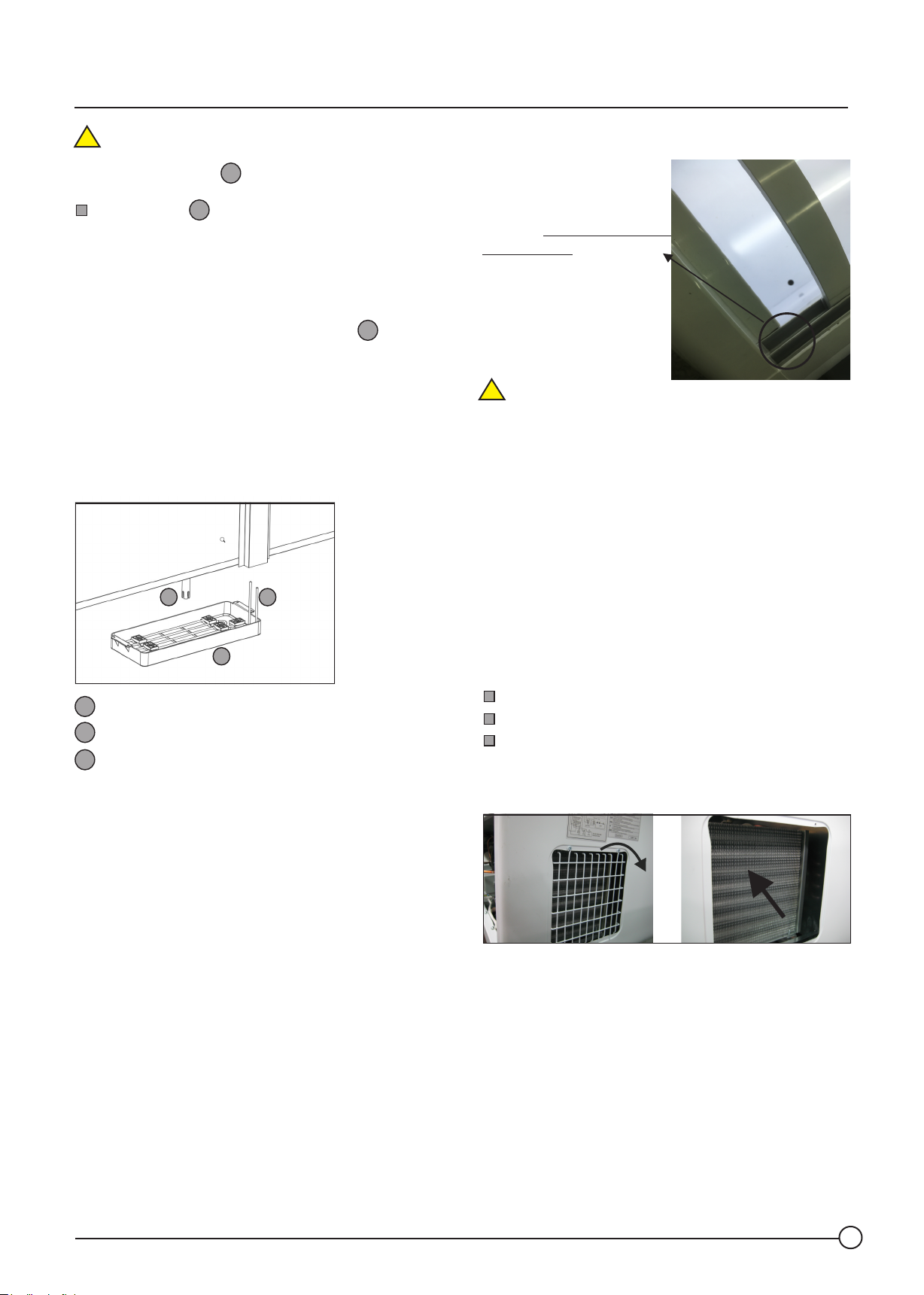
6.2.2.1 VERTICAL CABINET (mod. ARV 2.5DE)
The same concept as the previous system 6.2.2, however
the water tank is placed at the back of the appliance.
The water from defrosting evaporates due to the high
pressure heat generated by the compressor.
2
Evaporaon recipient
1
Drain
2
High temperature tube for water
3
evaporaon.
VERY IMPORTANT:
A complete defrosng of the appliance, for hygiene
reasons, is recommended 3 or 4 mes a year to eliminate
accumulated ice residues and dirt.
4
5
4
3
1
Figure 4.1
6.3. CLEANING OF THE PLASTIC LID FRAMES
The glass lids that equip your
appliance slide over a plastic
frame.
Clean the plastic profile where
the lid is fitted on a periodic
basis (as needed).
Use a slim nozzle of a
vacuum cleaner, a brush or
compressed air to remove
accumulated dirt.
ATTENTION! The plasc frame where the lids are fied
!
has a special lubricant to guarantee good slippage. Over
me, you may have to lubricate the chute. If necessary,
contact the aer-sales service.
6.4. CLEANING OF THE CONDENSER
As already mentioned in point 6 of the previous page, the
majority of our appliances is equipped with condensers
which do not require maintenance.
However, in Horeca models, ARV model the entire range is
equipped with a finning condenser that requires
maintenance.
IMPORTANT: Clean the strips of the condenser with the
frequency that you must establish, which depends on the
degree of cleanliness of the location where you install your
Remove the 2 screws that secure the rear grille.
Remove the grille.
Use the nozzle of the vacuum cleaner
compressed air at low pressure or to clean a hard non-
metal brush removing all dirt a dust between the
compresor fins.
This rule is applicable to our enre range of appliances,
with the excepon of the «DE» (Automac Defrosng)
model which depends on use, whereby once or twice a
year is sufficient.
ARV model
As ARV model works with a ventelitation system not static
as all other our products it is not necessary any special
concern about inside ice clean.
V2020_04
VERY IMPORTANT: On the ARV 2.5DE model,
we recomm end that the fins of the m icroch annel
condenser are cleaned every 30 days.
The procedure is very simple. It is the same as that of the
horeca model, previously mentioned, although in this case
the condenser is accessed from the top of the appliance.
12
Page 17
Instructions Manual
IMPORTANT!
Use protective gloves against cuts from sheets.
6.5. CLEANING OF GLASS
6.5.1. EXTERIOR CLEANING OF GLASS
The glass can be cleaned at any time, even while the
appliance is in operation. To clean the glass, it is not
necessary to remove the lid.
Clean the glass with a normal window cleaning
detergent. The ideal would be for it to be neutral.
6.5.2. INTERIOR CLEANING OF GLASS
6.6.2. INTERIOR CLEANING OF THE GLASS
When cleaning the inside part of the glass, several
precautions have to be taken.
Remove the lids of the appliance with cotton gloves.
Leave at ambient room temperature for 20 minutes.
Clean with a soft cotton cloth, lightly dampened with
pure clean and PH neutral water.
ATTENTION! During the cleaning of the windows,
!
avoid contact with the plastics and rubbers of the
appliance. Window cleaning products usually contain
solvents that can damage lid seal surfaces and their
functionality.
In the event of contact, clean with a damp cloth
immediately and then dry the surface very well with a dry
cloth.
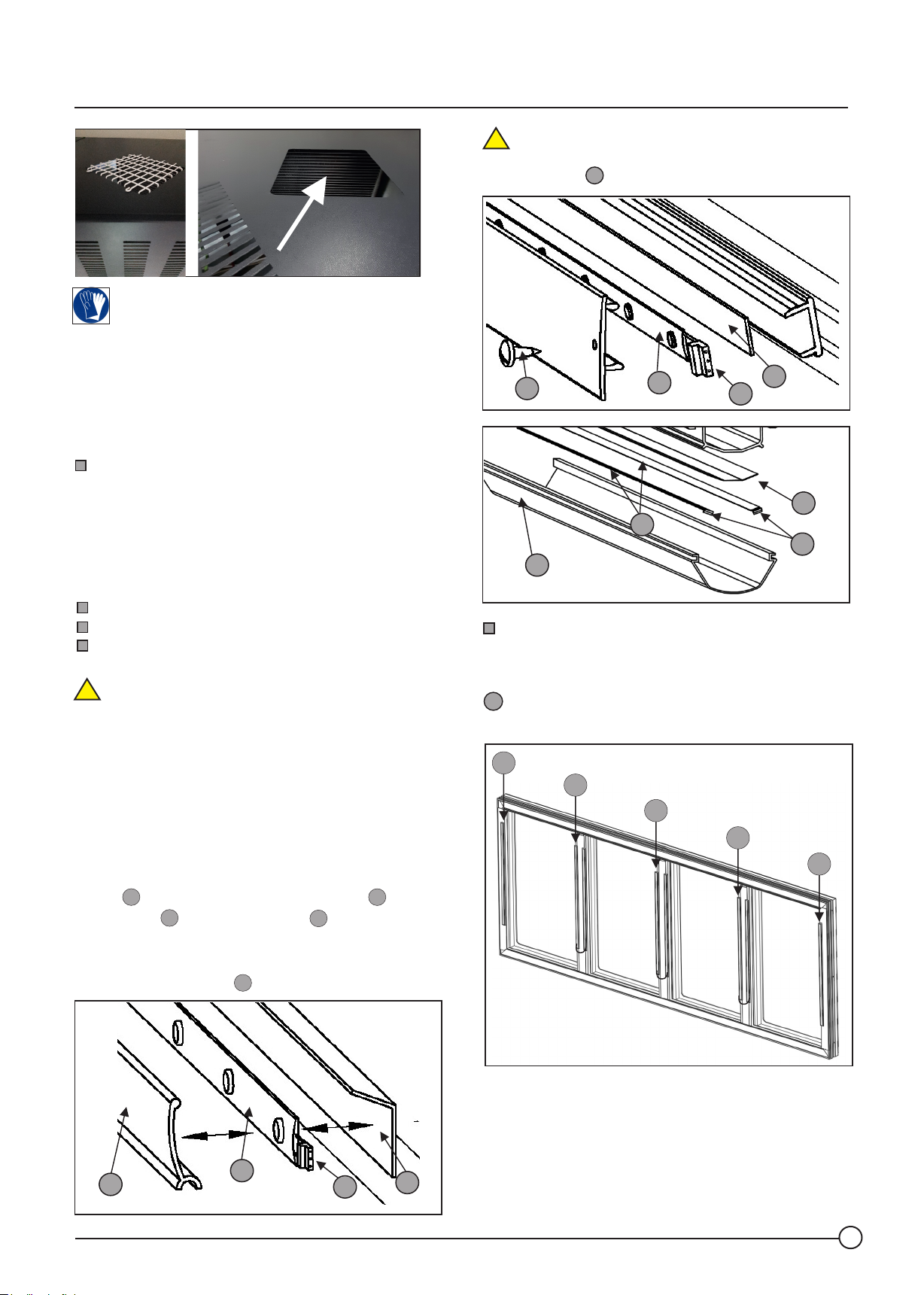
6.6 REPLACEMENT OF LED LIGHTING
If you want to replace the LED lighting, remove the acrylic
profile A that protects access to the LED strip B . Unplug
the connector © and remove the strip B . To install a new
LED strip, peel off the film that protects the adhesive
backing, plug in the connector and attach the strip from
that point along the plate D .
A
C
B
B
D
NOTE! On the SUPER, DUPLA or PANORAMICA TOPO
!
models, to remove the acrylic pofile, first remove the
fastening screws E .
E
E
SUPER TOPO
B
D
C
DUPLA 2.2
e CEP
D
B
C
A
The replacement of the LED in the vertical cabinet,
model ARV, is done in a different way than the previously
mentioned models and it is a little more complex.
In this specific case, the appliance is not supplied with the
. connector. The technicians of the after-sales service
C
will have to replace the lighting.
I5
I4
I3
I2
I1
A
V2020_04
SUPER e
PANORAMICA
VERY IMPORTANT!
Pay attention to the polarity when connecting the new LED or
LE D tr a n sfor m er. A LWAYS K EE P TH E SA M E W I RE
CONNECTION ORDER.
B
C
D
13
Page 18
Instructions Manual
6.7 REPLACING THE LED TRANSFORMER
All appliances with LED lighting have an upstream
110 /240 V - 12V transformer.
VERY IMPORTANT!
The appliances follow very strict normative criteria
When replacing the transformer, as well as any other
electrical component, always use the item recommended by
the manufacturer.
Changing to a different electrical component may jeopardise
the safety and compatibility tests the device has undergone.
7. PACKAGING OF THE PRODUCT / ACCESSORIES
7.1 INTERIOR
7.1.1 APPLIANCES WITHOUT DEFROSTING
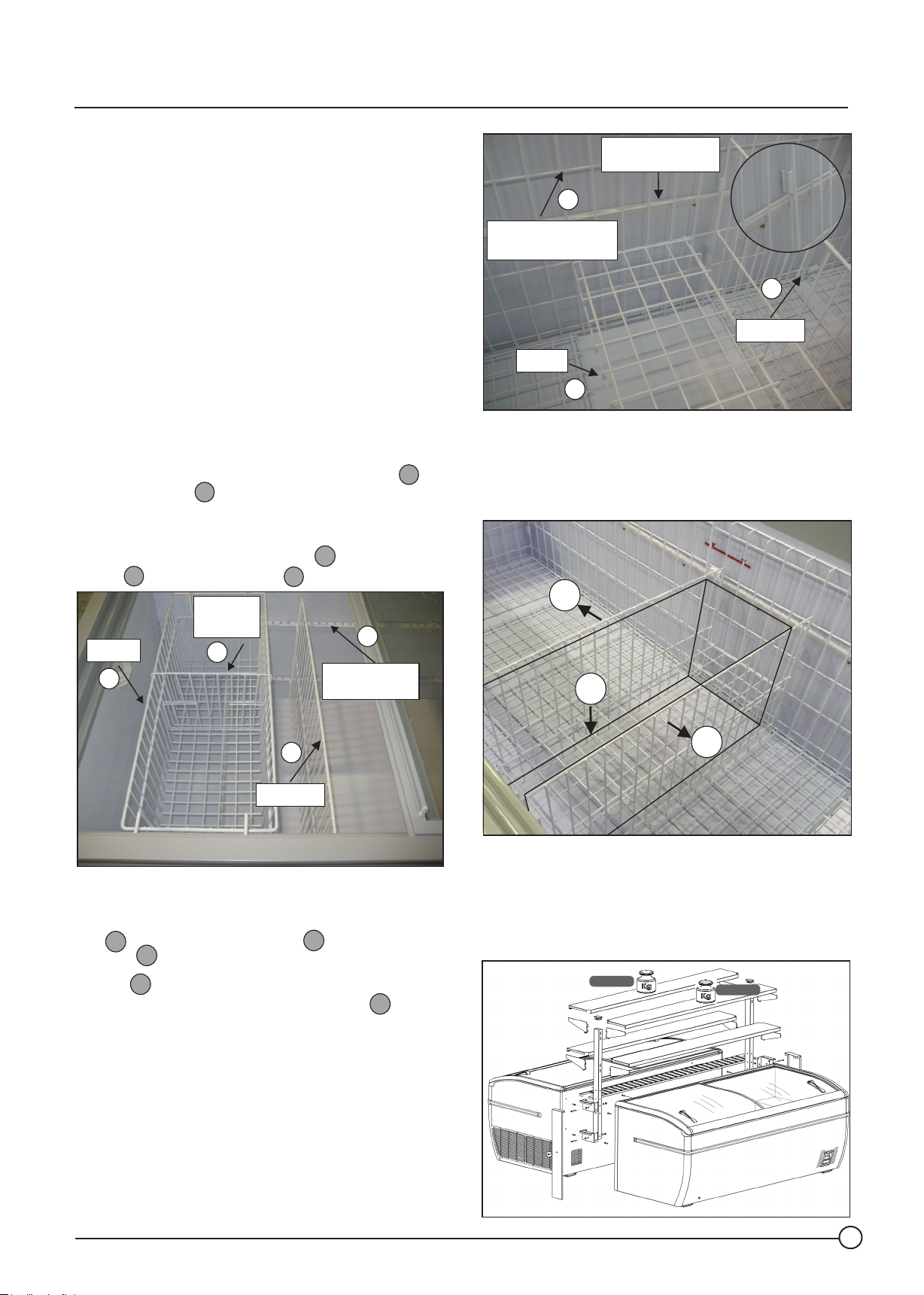
The product can be packaged in different ways. The walls of
your appliance are equipped with perforated guides for
fitting of partitions .
You are thus able to partition your products according to
your needs.
In addition to the separation partitions , there are also
baskets , and basket partitions .
1
Basket
1
3
4
2
Partition
Basket
2
Support grille
of partition
4
3
Water drainage
chute
6
Defrosting
protection grille
4
Partition
Tray
5
It also permits, in each area between trays, represented
below, the placing of parons and building different
compartments for the displayed product.
Do not forget that you are also able to raise the tray to the
height that you wish.
4
5
4
Partition
7.1.2 APPLIANCES WITH DEFROSTING
The appliances equipped with defrosting are supplied with
tray defrosting protection grilles and transversal
5
partitions .
The tray can be applied at different heights from the
surface, fixed to the defrosting protection grilles .
4
5
6
6
4
7.2. EXTERIOR
In the PLUG-IN system, there is the possibility of supplying
(optional) extra shelves, for external display of other
products.
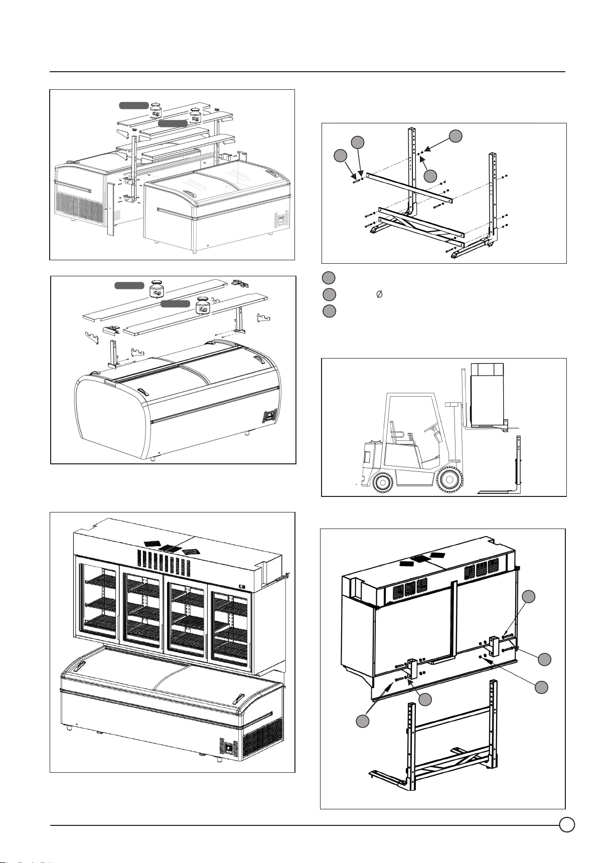
The figure below provides an example of the assembly of
shelves.
MAX. 25 Kg
MAX. 25 Kg
V2020_04
mod.PANORAMICA
14
Page 19
Instructions Manual
MAX. 25 Kg
MAX. 25 Kg
MAX. 25 Kg
MAX. 25 Kg
mod.SUPER
7.3 ARV 2.5 VERTICAL CABINET FIXING BRACKET
7.3.1 ATTACHMENT STRUCTURE
B
C
A
B
M12 x 110 mm Screws
A
Washer 12
B
Nuts M12
C
7.3.2- TRANSPORT AND RAISING THE APPLIANCE INTO
POSITION
mod.DUPLA
For information on the installation and supply of this
material, contact the after-sales service.
ARV + SUPER
!
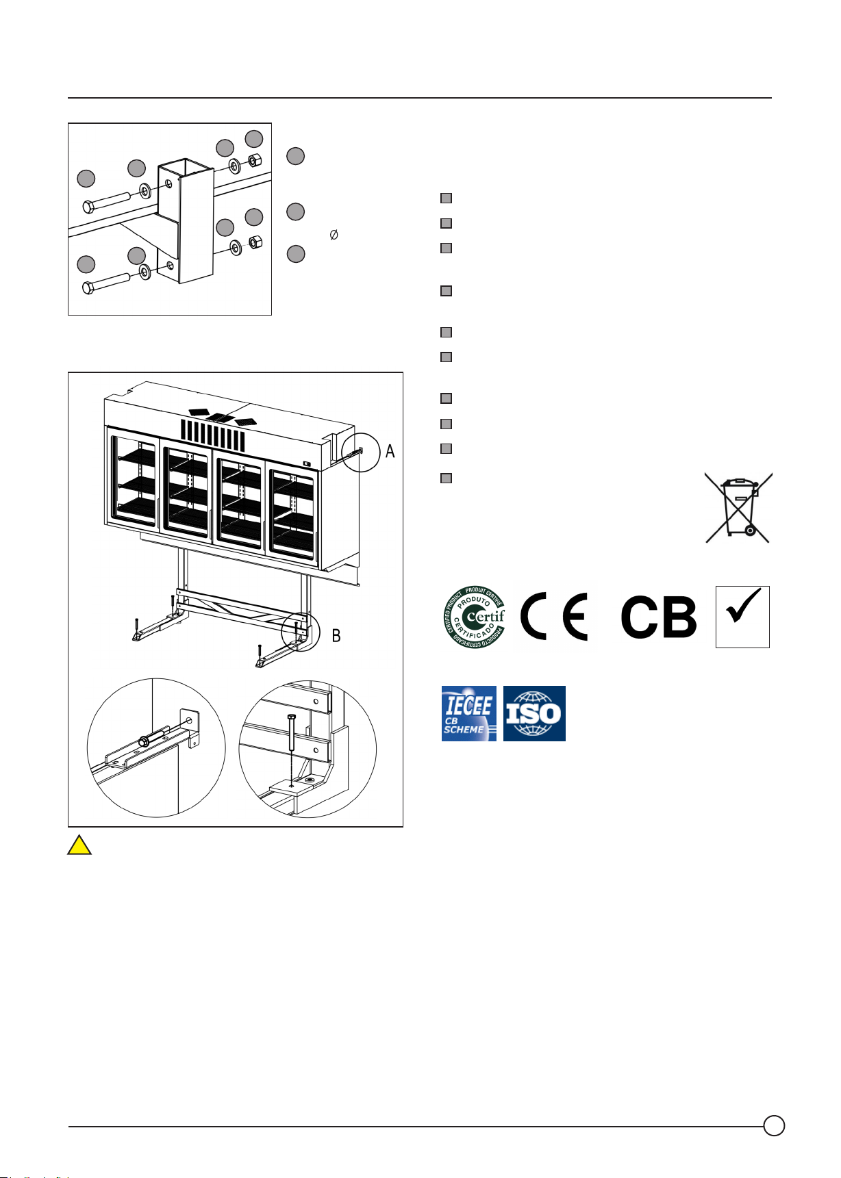
7.3.3- ATTACHMENT OF THE APPLIANCE'S SUPPORT
E
D
F
E
D
V2020_04
15
Page 20
Instructions Manual
F
E
D
D
7.3.4- ATTACHMENT OF THE STRUCTURE TO THE WALL
E
F
E
E
D
Screws
M16 x 110 mm
E
Washer 16
F
Nuts
Hex M16
8. REGULATION / CERTIFICATION
The appliance you have purchased complies with the
following directives/standards
Low Voltage: 2014/35/UE
Electromagnetic compatibility: 2014/30/UE
Specific requirements for commercial refrigeration
appliances: EN/IEC 60335-2-89
Domestic and similar electrical appliances:
EN/IEC 60335-2-24
Electrical Safety: EN/IEC 60335-1
Electromagnetic Compatibility - Requirements for
domestic appliances: EN 55014 / EN 61000 / CISPR 14-1
Definitions and Test Criteria: ISO 23953-1
Restriction on the use of hazardous substances RoHs
Waste of electric and electronic equipment WEEE
In this regard, follow the regulations of
your country with regard to the elimination of
the appliance.
NOTE! This appliance must not be disposed of
with your household waste.
note A note B
VERY IMPORTANT:
!
The support structure of the vertical cabinet (model ARV)
must be attached to the floor and the side fixing brackets
must be attached to the wall.
RoHS
2002/95/CE
V2020_04
16
 Loading...