

Page 1
ASSEMBLY INSTRUCTIONS
TM
F5000
F6000
PRE-ASSEMBLY
Before you begin: These instructions will guide you in properly assembling the unit. Please review all the steps before beginning assembly.
Carefully adhere to the Assembly Instructions and Owner’s Manual to help ensure user safety and product integrity.
1. It is your responsibility to familiarize yourself with the proper use of the equipment and the inherent risks of inversion, such as falling on your
head or neck, pinching, entrapment or equipment failure.
2. This product is not designed for persons over 6’6” (198 cm) or 300 lbs (136 kg). Structural failure could occur or head/neck may impact floor
during inversion. Serious injury or death could result.
3. DO NOT use the equipment without a licensed physician’s approval and a review of the medical contraindications, as noted in the Owner’s Manual.
4. Failure to assemble and/or use the equipment as directed may void the manufacturer’s warranty on this product and could result in injury or death.
5. DO NOT use the inversion table until you have thoroughly and carefully read the Owner’s Manual, viewed the Instructional Video, reviewed all
other accompanying documents, and inspected the equipment.
6. The steps in the video directly coincide with the steps detailed in these Assembly Instructions.
7. Choose a level surface for assembling and operating the table.
8. Follow each step in sequence. Do not skip ahead.
9. Make sure that all fasteners are secure.
10. PRIOR TO USE, test and inspect the table. Make sure the table rotates smoothly to inverted position and back.
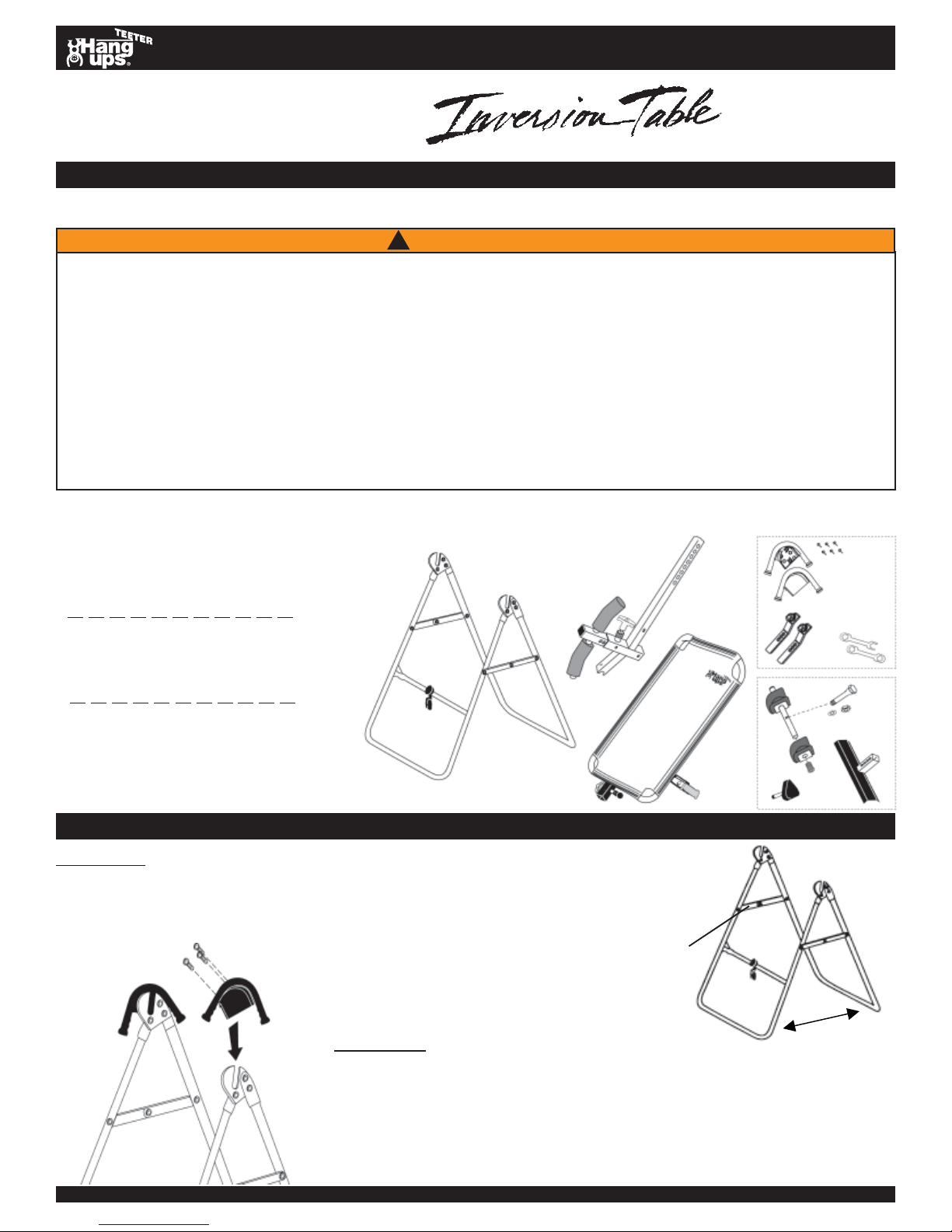
Carefully remove the individual parts from the carton. You should have all of the items listed below. If any items are missing or damaged, contact
your retailer or customer service directly (See Pg. 4).
ITEMS FOR ASSEMBL Y ITEM #’s
A-frame base F51002
Main shaft w/ front ankle clamp F51039
Table frame with mat F51021
Hand grips (2) and F51069
1/2”
(13mm) hex bolts (6) H11202
Two (2) roller hinges F51064
Two (2) wrenches F51088
Rear bar with ankle clamps F51052
2”
(51mm) Hex Bolt / Nut / Washer F51087
Black Rubber Plug F51056
Triangle-head knob F51063
Foot platform F51060
F61021 (F6000)
(F5000)
&
TM
U.S. and foreign patents apply. Other foreign p atents pending.
!
W ARNING
F51002
F51021 (F5000)
F61021 (F6000)
F51039
F51056
F51069
F51064
F51052
F51063
H11202
Bolts may be
packaged
separately or
assembled in
hand grips.
F51088
F51087
F51060
ASSEMBLY
STEP ONE
Assemble the A-frame Base (F51002)
• Open the A-frame and make sure that the spreader arms are locked flat.
(See Figure 1)
NOTE: Bolts may be
(L)
packaged separately
or assembled in
hand grips.
Figure 2
(R)
Figure 1
Spreader Arms
STEP TWO
front rear
Install Hand Grips (F51069) on A-frame Base (F51002)
• Place one of each hand grip (left / right) over the outside edge of the corresponding hinge plate. (See Figure 2)
• Insert three 1/2” (13 mm) hex bolts (H1 1202) through the hinge plate into each
hand grip. Use the wrenches provided to tighten the bolts, being careful not to
over tighten.
DO NOT DISCARD - KEEP FOR FUTURE REFERENCE.
Page 2
ASSEMBLY
STEP THREE
F5000 F6000
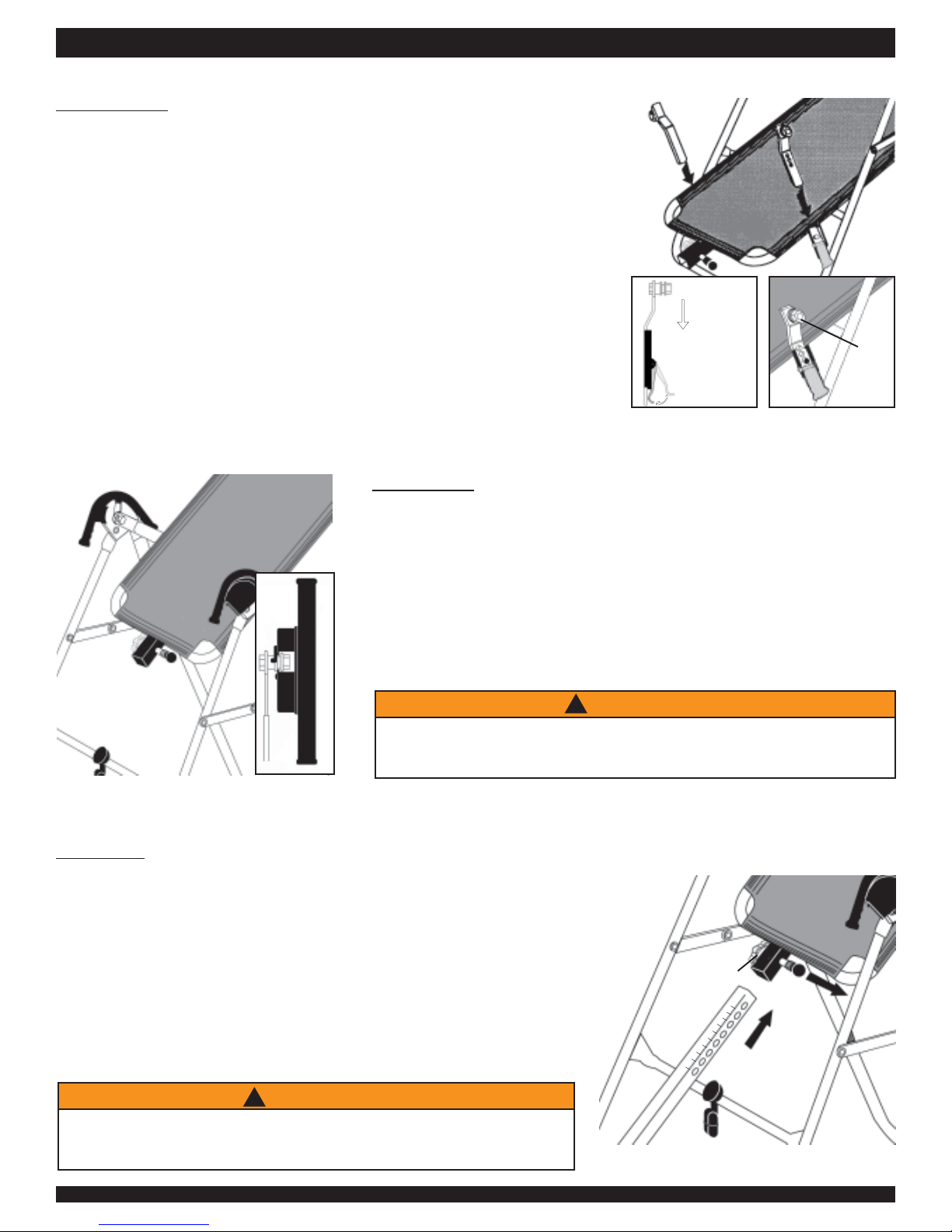
Install Roller Hinges (F51064) to T able Frame (F51021 or F61021)
• For ease of assembly, rest the t able frame against the crossbar at the
front of the A-frame.
• Open the cam locks on each side of the table frame.
• With the grooved pivot pins facing out, insert the roller hinges into the
brackets on each side of the table frame. (See Figure 3) The roller hinges
will slide between the cam locks and the brackets. (See Figure 3A)
• Make sure that the roller hinges are in the same hole setting on both
sides.
• Push down on the cam lock to secure the hinge. Figure 3B shows the
roller hinge engaged correctly (in Setting C).
Refer to the Owner’s Manual for an explanation of the hole settings.
We suggest using Setting C to start.
Figure 4
STEP FOUR
Attach the T able Frame (F51021 or F61021) to the A-frame (F51002)
• Holding each side near the roller hinges, pick up the table frame and stand at
the front of the A-frame. Lower each pivot pin into the A-frame hinge plates at
the same time. (See Figure 4) Figure 4A shows the correct placement of the
pivot pin into the hinge plate.
• Make sure that both pivot pins are seated at the base of the slot in the
hinge plate.
• Check to make sure that the self-locking hooks have closed over both
pivot pins and that the table rotates smoothly .
Figure 3
Figure 3A
F5000 F6000
Hinge
In Setting C
into
bracket
pivot
pin
Close
cam lock
Figure 3B
Failure of the self-locking hooks to close over both pivot pins
is indication of improper assembly and if not corrected,
could result in serious injury or death.
Figure 4A
STEP FIVE
F5000 F6000
Insert the Main Shaft (F51039) into the Table Frame (F51021 or F61021)
• Loosen the de-rattler knob on the main shaft housing.
• With the height adjustment settings on the main shaft facing up, slide the
end of the main shaft into the blue bushing in the main shaft housing. (See
Figure 5)
• Pull out the height selector locking pin to allow the main shaft to slide in
further. For the purpose of easy assembly, slide the main shaft in all the
way and release the pin in the storage setting. (Refer to the Owner’s
Manual for proper height adjustment before use).
• Tighten the de-rattler knob.
!
WARNING
!
Read the Owner’s Manual for information on
selecting the correct user height setting.
Improper settings could result in serious injury or death.
!
WARNING
Figure 5
de-rattler
knob
Assembly Instructions #LF5100 Pg. 2
Page 3
ASSEMBLY
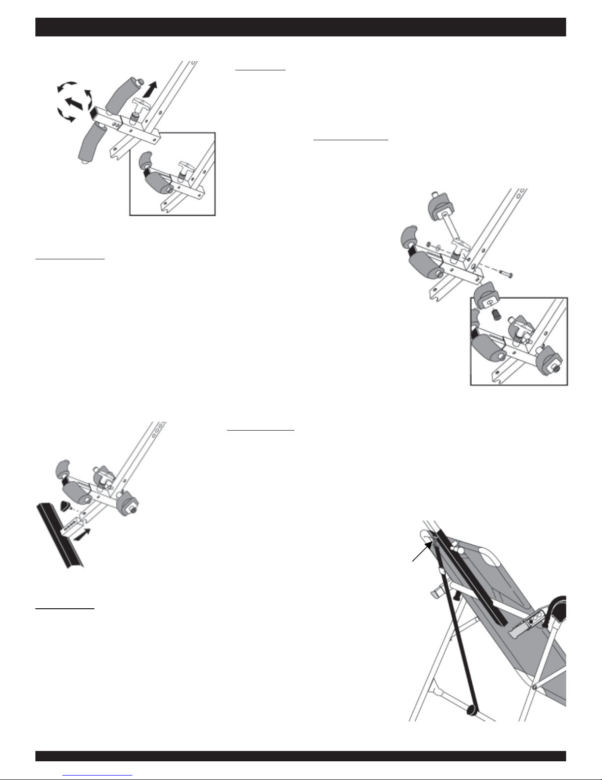
Figure 6
Figure 6A
STEP SIX
Rotate the Front Ankle Clamps on the Main Shaft (F51039)
• Pull up on the locking pin for the ankle clamps. (See Figure 6)
• Pull out the spring loaded front ankle clamps until the square tubing is
disengaged from the main shaft. Do not overstretch the spring.
• Rotate clamps
Figure 6A) Re-engage the square tubing into the main shaft.
counterclockwise so that the pin holes face up. (See
STEP SEVEN
Assemble Rear Bar with Ankle Clamps (F51052)
• With the rounded corners of the rear foam ankle piece facing down, insert
the rear bar with one ankle clamp into the large hole at the bottom of the
main shaft. (See Figure 7)
• Align the hole in the rear bar with the hole on the main shaft and insert
the Hex bolt (F51087) into the holes from the rear. Install the washer and
nut; tighten with the wrenches provided.
• Slip the other foam ankle clamp with silver backing (rounded corners
down) onto the rear bar and push the black rubber plug (F51056) into the
bar. See Figure 7A for correct assembly.
Figure 7
Figure 7A
STEP EIGHT
Assemble Foot Platform (F51060)
Figure 8
• Slide the foot platform into the bottom of the main shaft and adjust to
desired height. (See Figure 8) Refer to the Owner’s Manual for proper user
settings before use.
• Insert the Triangle-head knob (F51063) through the predrilled holes and
tighten.
STEP NINE
Attach the Tether Strap to Limit the Degree of Rotation
• Unfold the tether strap and snap it into the U-bar on the underside of the
table frame. (See Figure 9)
• The tether strap is adjustable to stop the inversion table at any desired
angle.
Figure 9
Hook tether
strap here.
Assembly Instructions #LF5100 Pg. 3
Page 4
STEP TEN
T esting the Assembly
PRIOR TO USE:
• T est the t able by hand for smooth and steady rotation.
• Ensure all fasteners are secure.
You have completed the assembly of your Teeter Hang Ups® Inversion Table.
• Read your Owner’s Manual thoroughly before using the inversion table. Improper
settings could result in serious injury or death.
• For your reference, the table’s serial number can be found at the base of the table
frame on the back.
• Please complete and mail your warranty card, or submit it on-line at
www.teeterhangups.com.
POST ASSEMBLY ADJUSTMENTS
MAINTENANCE
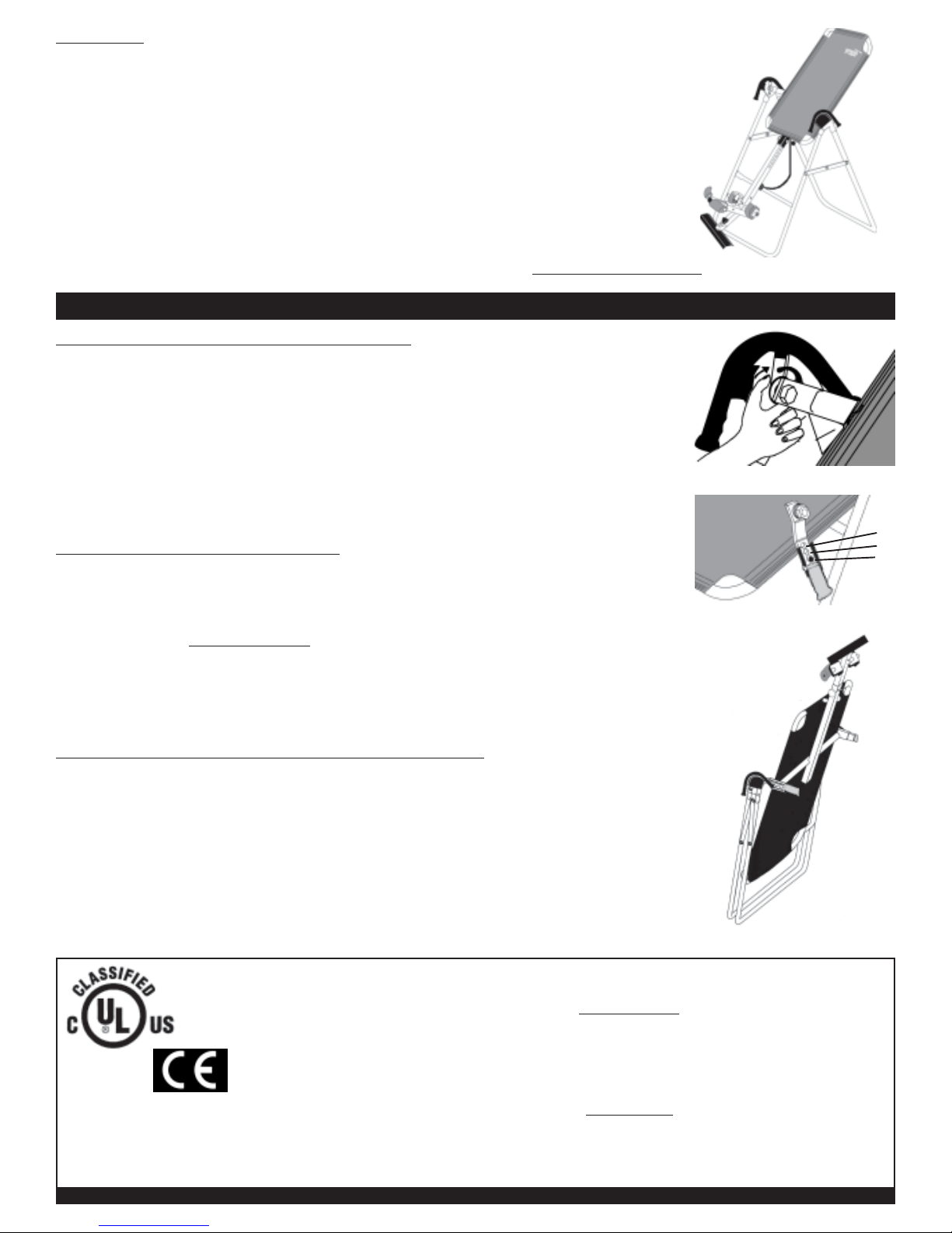
CHANGING THE ROLLER HINGE SETTING
• Stand with your legs on either side of the main shaf t.
• Reach under each roller hinge with your index fingers. Use your thumbs to release the
locks over the roller hinges. (See Figure 10)
• Lift both sides of the table out of the A-frame at the same time. Y ou may rest the t able
on the crossbar of the A-frame.
• Unlock the cam locks for each roller hinge. Change the roller hinges to the desired
setting (A, B, or C, from most aggressive to least aggressive). (See Figure 1 1)
• Relock the cam locks. Replace the roller hinges into the hinge plates of the A-frame.
STORING THE INVERSION TABLE
• Loosen the de-rattler knob.
• Pull the height selector locking pin and slide the main shaft in all the way to the
ankle clamp assembly . Engage the pin in the storage setting.
• Rotate the table opposite from use until the table has turned 180 degrees and rests
against the cross bar on the A-frame.
• The legs of the A-frame base may then be folded together for comp act storage.
(See Figure 12). WARNING: This operation may pinch fingers if not done
slowly and carefully.
TABLE MAT: REMOVING / CLEANING / TIGHTENING
• Y ou may find it easier to remove the nylon mat while the table is in its storage position.
• Pull up on the plastic tension clips to loosen the adjustment straps.
• Release one corner at a time, then slide the mat off the frame.
• The mat should be washed in cold on gentle cycle. Replace the mat on the table
frame while still wet.
• If you feel the nylon mat needs to be tightened, pull the adjustment straps on the
back of the mat.
STORAGE
Shows pin in
Setting C
Figure 10
A
B
C
Figure 11
Figure 12
For additional languages in Spanish, French, Dutch, German, Italian or Portuguese, please contact customer service.
Classified as Medical
Equipment, part I in accordance
with UL 2601-1 and CAN/CSA
C22.2; General Requirements
for Safety in accordance with
Underwriters Laboratories, Inc.
* any modification to this device
will void the UL Classification
U.S. and foreign patents apply. Other foreign patents pending.
Teeter Hang Ups® is a registered trademark of STL International, Inc.
and Inversion International, Ltd.
Specifications subject to change without notice.
© COPYRIGHT 2003, STL International, Inc.
International Law Prohibits Any Copying, 11/03-7
Assembly Instructions #LF5100 Pg. 4
For information about the Teeter Hang Ups® 5-year warranty, or if you have any problems
assembling the equipment or questions about its use, please contact Customer Service at the
appropriate location below:
USA & Canada:
STL International, Inc.
9902 162nd St. Ct. E., Puyallup, W A 98375
Toll Free (Phone) 800-847-0143 (Fax) 800-847-0188
Local (Phone) 253-840-5252 (Fax) 253-840-5757
(email) [email protected] (web) www.TeeterHangUps.com
International:
Inversion International, Ltd.
PO Box: AP 59245, New Providence Island, Bahamas
(Phone) +1-242-362-1001 (Fax) +1-242-362-1002
(email) [email protected] (web) www.InversionInternational.com
 Loading...