

Page 1

EP-950
Inversion Table
Assembly Instructions
TM
Page 2
PRE-ASSEMBLY
Before you begin: Review all steps before beginning assembly and read
all precautions before using the inversion table. Carefully adhere to the
Assembly Instructions and Owner’s Manual to help ensure user safety
and product integrity.
WARNING
!
1. It is your responsibility to familiarize yourself with the
proper use of the equipment and the inherent risks of
inversion, such as falling on your head or neck, pinching,
entrapment or equipment failure.
2. This product is not designed for persons over 6’6” (198
cm) or over 300 lbs (136 kg). Structural failure could occur
or head/neck may impact fl oor during inversion. Serious
injury or death could result.
3.
DO NOT use the equipment without a licensed physician’s
approval and a review of the medical contraindications, as
noted in the Owner’s Manual.
4. Failure to assemble and/or use the equipment as directed
may void the manufacturer’s warranty on this product and
could result in injury or death.
5.
DO NOT use the inversion table until you have thoroughly
and carefully read the Owner’s Manual, viewed the
DVD, reviewed all other accompanying documents, and
inspected the equipment.
6. Choose a level surface for assembling and operating the
table.
7. Follow each step in sequence. Do not skip ahead.
8. Make sure that all fasteners are secure.
9.
ALWAYS test and inspect the table. Make sure the table
rotates smoothly to inverted position and back.
10. Replace defective components immediately and/or keep
the equipment out of use until repair.
Page 3
PRE-ASSEMBLY
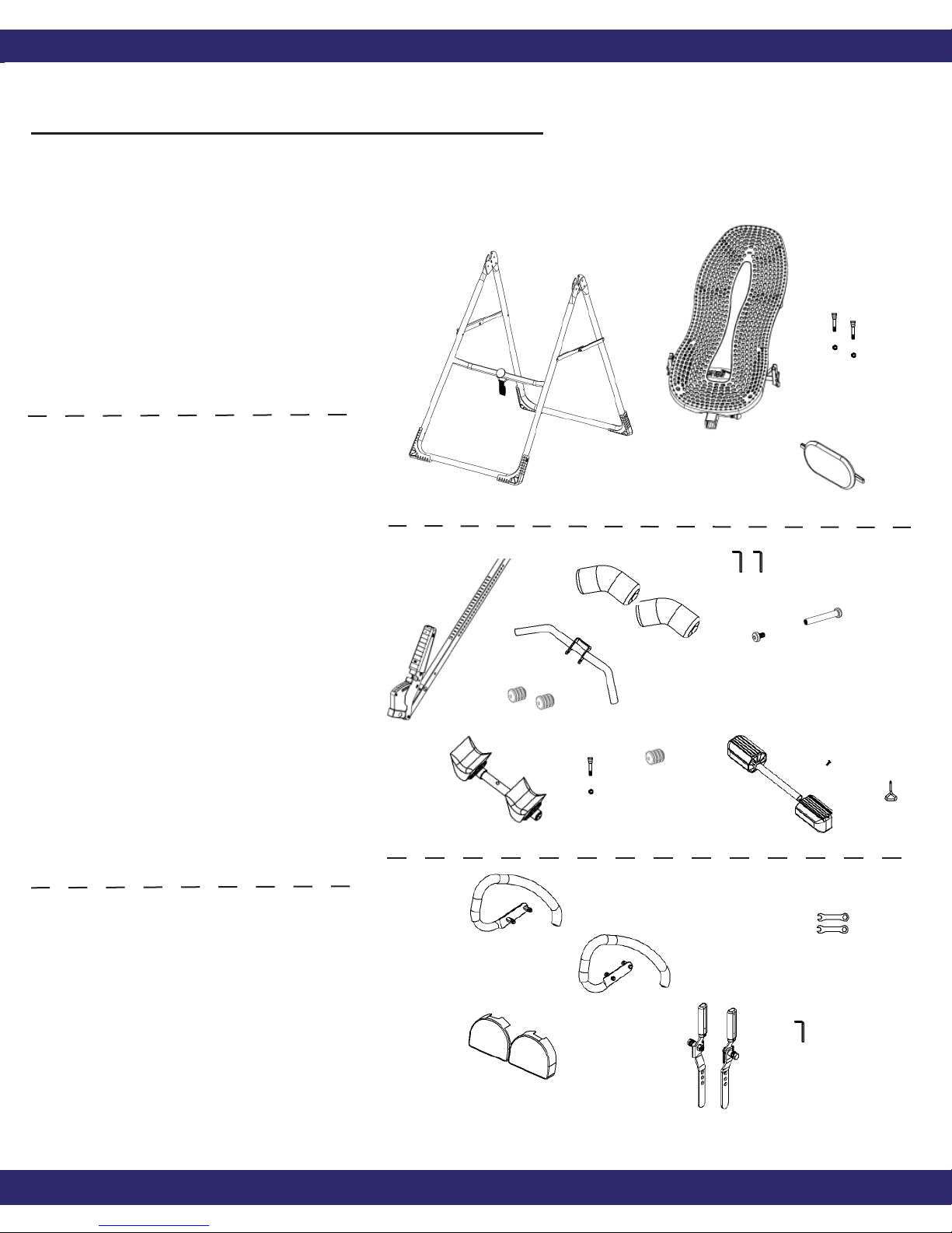
ITEMS FOR ASSEMBLY
Carefully remove the individual parts from the carton. You should have all
of the items listed below. If any items are missing or damaged, contact
Customer Service at 1-800-847-0143.
Items for Assembly Item Numbers
A-frame Base (EP-1100)
EZ-Angle Tether (F5-1008)
Table Bed Assembly (EP-1140)
Bolts and Nuts (EP-1149)
Head Pillow (EP-1105)
(F5-1008)
(EP-1149)
Main Shaft with
Ankle Lock System (IA-1107)
Front Ankle Assembly
Ankle Bar (F5-1047)
Rubber Plugs (2) (F5-1056)
Foam Rollers (2) (F5-1051)
Bolt Sleeve (IA-1110)
Sleeve Screw (IA-1112)
Rear Bar Assembly
Rear Bar w/
Heel Cups (IA-1113)
Bolt/Nut (IA-1116)
Rubber Plug (F5-1056)
Foot Platform
(IA-1107)
Assembly
Foot Bar (IA-1119)
Foot Pieces (2) (IA-1118)
Screw (IA-1123)
Screwdriver (F5-1130)
Over EZ Handles
(EP-1100)
(IA-1113)
(F5-1047)
(F5-1056)
(IA-1116)
(GL-9518)
(GL-9522)
(GL-9523)
(EP-1140)
(F5-1051)
(F5-1056)
(IA-1149)
(IA-1112)
(IA-1119)
(IA-1118)
(EP-1105)
(IA-1110)
(IA-1123)
(F5-1130)
Left Handle (GL-9518)
(F5-1088)
Right Handle (GL-9522)
Threaded Bolts (4) (GL-9523)
Shrouds (GL-9524)
1/4” Bolts (4) (GL-9525)
Roller Hinges (2) (TR-1001)
Wrenches (2) (F5-1088)
(GL-9524)
(GL-9525)
Bolts will
come preassembled
in handles
and
shrouds.
(EP-1150)
(TR-1001)
Allen Wrench (EP-1150)
Teeter Hang Ups EP-950
2
Page 4
ASSEMBLY
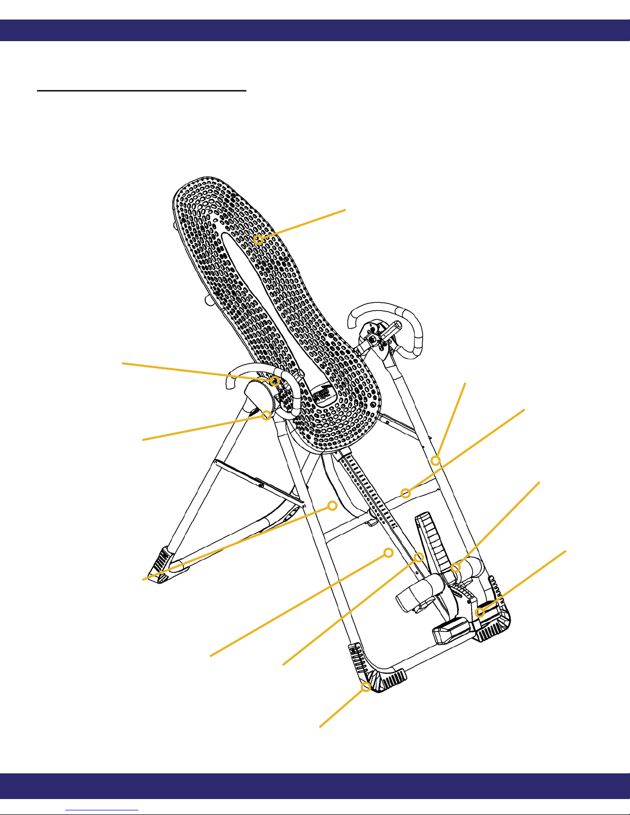
Before Beginning
Before reading further, study the drawing below to familiarize yourself
with the important components of your new Teeter Hang Ups
inversion table.
Table Bed
Traction Handles
Over EZ-Handles
EZ-Angle
Tether Strap
A-frame
Crossbar
Rear and
Front Ankle
Clamps
Adjustable
Foot Platform
Main Shaft
Ankle Lock
System
Stability Feet
Teeter Hang Ups EP-950
3
Page 5
ASSEMBLY
Step One
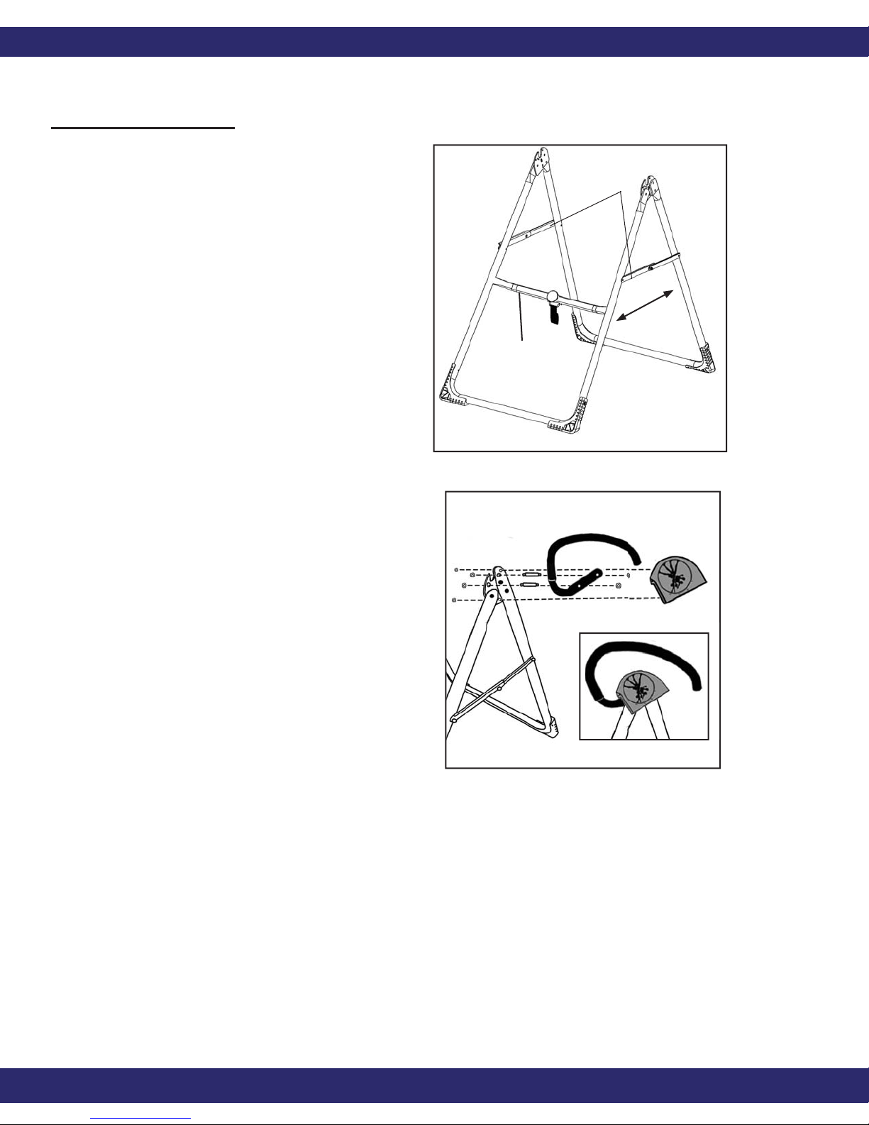
Assemble the A-frame Base
(EP-1100) and Install the
Handles (GL-9518, GL-9522)
and Shrouds (GL-9524)
• Open the A-frame and make sure
the spreader arms are locked.
Rest the A-frame on the fl oor
(Figure 1). The Crossbar is at the
front.
• Insert two double threaded bolts
(GL-9523) through the base of
the Left Handle (marked with
an “L”) and hand tighten on the
outside with the nuts provided.
(See Figure 2) Line up and insert
the opposite end of the bolts
Right
Crossbar
NOTE: Nuts and bolts may
be packaged separately or
assembled in
handles and shrouds.
spreader arms
front
Figure 1
Left
back
Figure 2
through the corresponding 1/3”
holes on the outside of the hinge
plate. Loosely tighten with nuts,
then use the wrenches provided
to tighten both sets of nuts,
being careful not to over tighten.
Repeat with the Right Handle.
• Place each shroud over the
outside edge of the corresponding
handle. Line up and insert the
shroud bolts (GL-9525) through
the smaller 1/4” holes in the
hinge plate (See Figure 2). Use
the wrenches provided to tighten
the nuts, being careful not to over
tighten.
(L)
Figure 2A
Teeter Hang Ups EP-950
4
Page 6
ASSEMBLY
Upper Support Arms
Step Two
Attach the Upper Support
Arms to the Table Bed
(EP-1141)
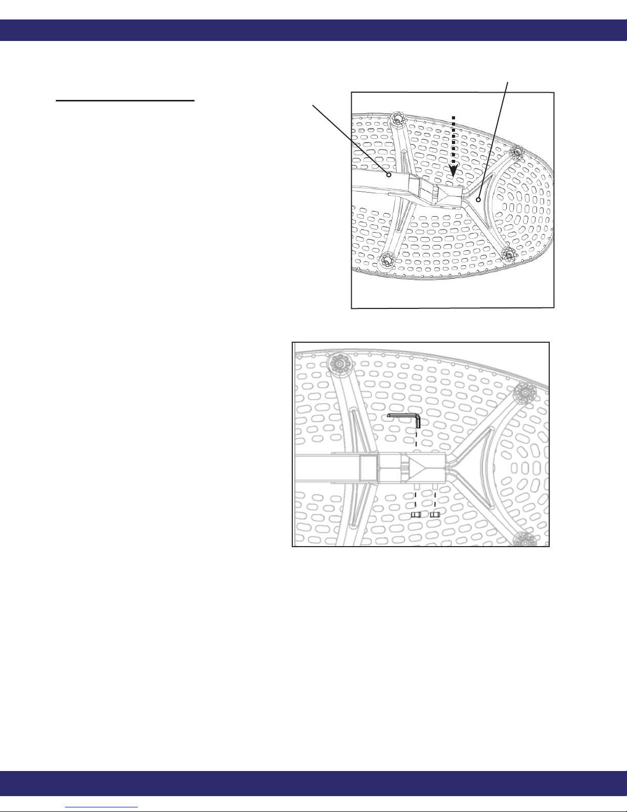
• Before following this step, make
sure you have read the orange
insert that came attached to the
Table Bed.
• Place the Table Bed face down
on the fl oor and push down on
the Support Beam, so the two
holes align evenly with holes
at the base of Upper Support
Arms (Figure 3). You may have
to exert extra pressure to ensure
Support Beam
Figure 3
the Support Beam slides over the
rubber spacers.
• Insert the two bolts (EP-1149)
through the rubber spacers and
into the open holes.
• Fasten each bolt with a nut.
• Use the Allen Wrench to steady
(EP-1150) the bolts, tighten the
nut onto the bolt with the larger
wrench (F5-1088) (Figure 4).
Repeat with the second bolt.
Figure 4
Teeter Hang Ups EP-950
5
Page 7
ASSEMBLY
Step Three
Install the Roller Hinges
(TR-1001) onto the Table Bed
(EP-1140)
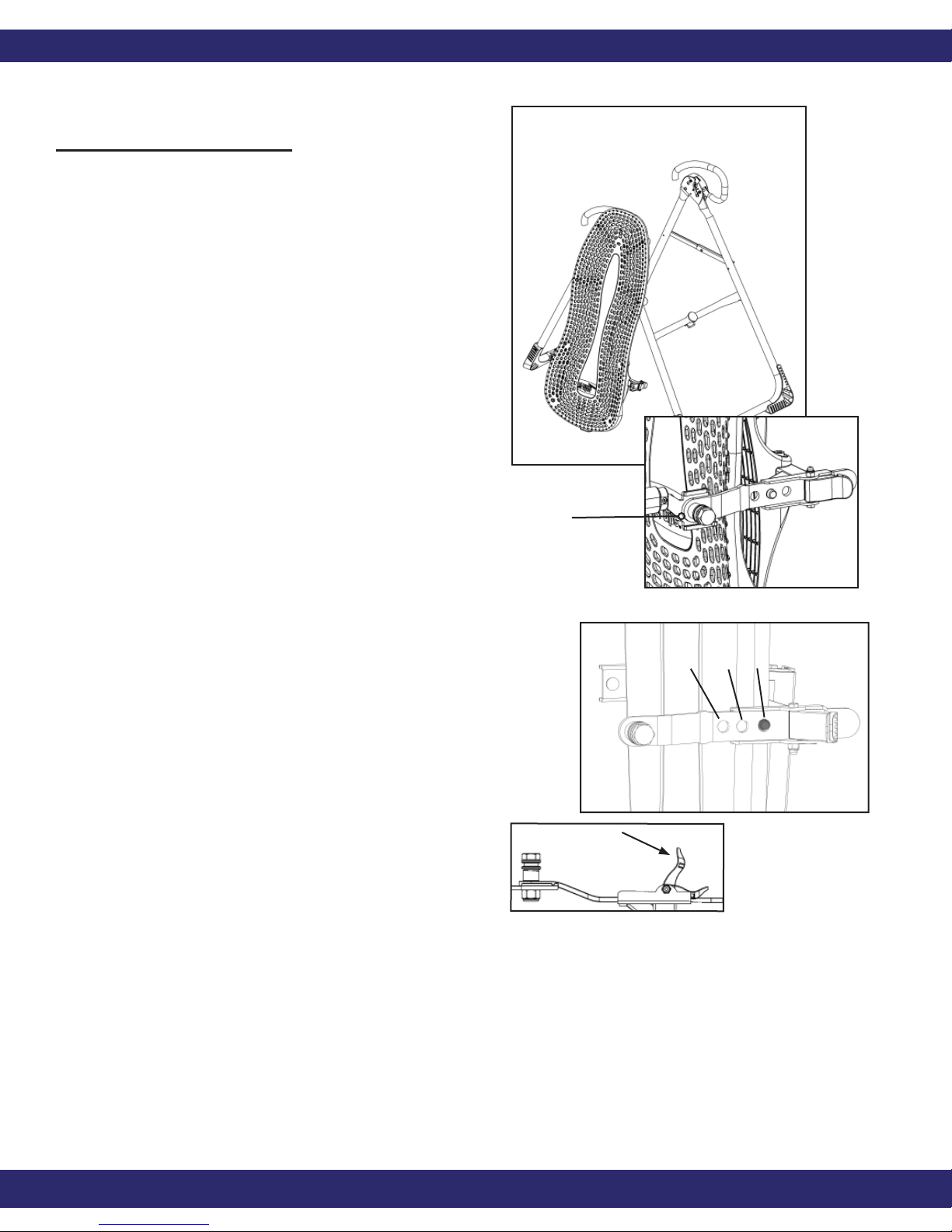
• For ease-of-assembly, rest the
Table Bed against the side of the
A-frame (Figure 5).
• Open the Cam Locks on each side
of the Table Bed (Figure 5A).
• With the Pivot Pins facing
outward, insert the Roller Hinges
into the brackets on each side of
the Table Bed. The Roller Hinges
must slide between the Cam
Locks and the brackets.
Figure 5
Pivot Pin
• Make sure the Roller Hinges are
in the same hole setting on both
sides. Figure 6 shows the Roller
Hinges engaged correctly in
setting C.
• Push down on the Cam Locks
(Figure 6A) to secure the hinges.
NOTE: Refer to the Owner’s
Manual for an explanation of the
hole settings. If you are unsure,
use setting C to start.
Figure 5A
A B C
Figure 6
Figure 6A
Teeter Hang Ups EP-950
6
Page 8
ASSEMBLY
Step Four
Attach the Table Bed
(EP-1140) to the
A-frame (EP-1100)
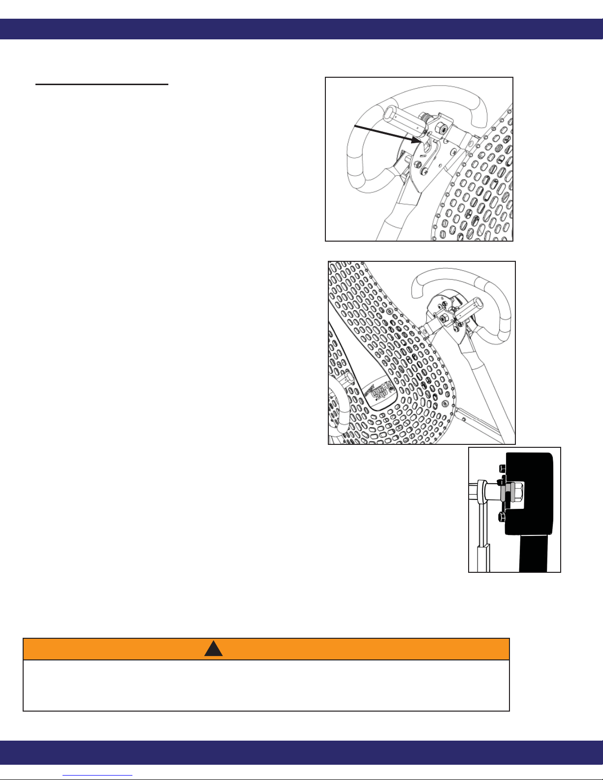
• Holding each side near the
Roller Hinges, pick up the
Table Bed and stand at the
front of the A-frame where
the Crossbar is located. Lower
each Pivot Pin into the A-frame
hinge plates one at a time
(Figure 7). You may need to
push outward on the A-frame
in order to slide the second
Figure 7
Pivot Pin into the hinge. Figure
9 shows the correct placement
of the Pivot Pin into the hinge
plate.
• Make sure that both Pivot Pins
are seated at the base of the
slot in the hinge plate. Check
to make sure that the selflocking hooks have closed over
both Pivot Pins (Figure 9), and
the table rotates smoothly.
Figure 8
Figure 9
WARNING
!
Failure of the self-locking hooks to close over both Pivot Pins is indication of
improper assembly and if not corrected, could result in serious injury or death!
Teeter Hang Ups EP-950
7
Page 9
ASSEMBLY
Step Five
Insert the Main Shaft (IA-1107) into
the Table Bed (EP-1140)
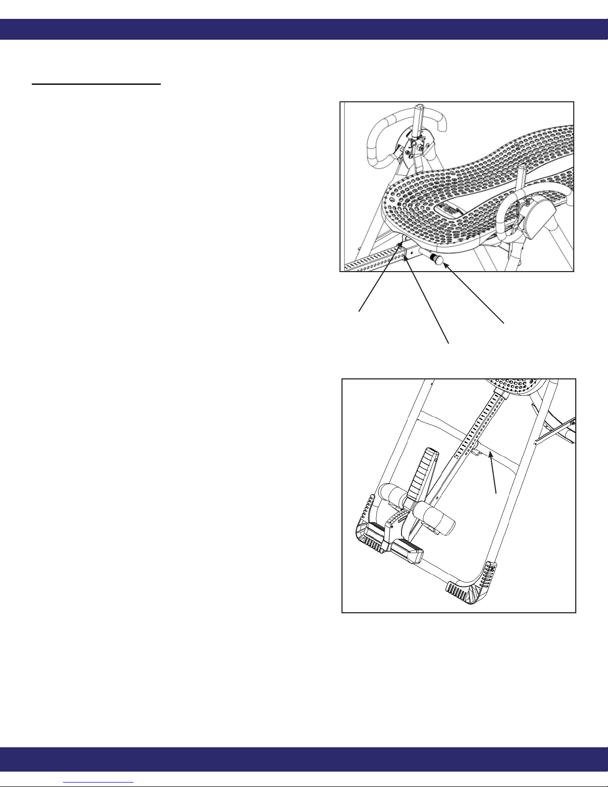
• Loosen the De-rattler knob on the Main
Shaft Housing.
• With the height adjustment settings on
the Main Shaft facing up, slide the end
of the Main Shaft into the Main Shaft
Housing on the Table Bed.
• Pull out the height-selector locking pin
to allow the Main Shaft to slide in
farther (Figure 10). For the purpose of
easy assembly, slide in the Main Shaft
and release the pin in the last height
setting (Refer to the Owner’s Manual
for proper height adjustment before
use).
NOTE: The De-rattler knob is an
optional accessory that helps prevent
a slight shift in the table when you
invert. The security of the product is
not compromised if you choose not to
tighten the knob.
• The Main Shaft must rest against the
Crossbar of the A-frame
(Figure 11). The Crossbar prevents
the table from rotating forward when
the user steps on the Foot Platform.
De-rattler Knob
Main Shaft
Housing
Crossbar
Figure 10
Height-Selector
Locking Pin
If the Main Shaft does not rest on the
Crossbar as shown in Figure 11 then
the Table Bed has been assembled
backwards onto the A-frame and this
must be corrected before use.
Teeter Hang Ups EP-950
Figure 11
8
Page 10
ASSEMBLY
Step Six
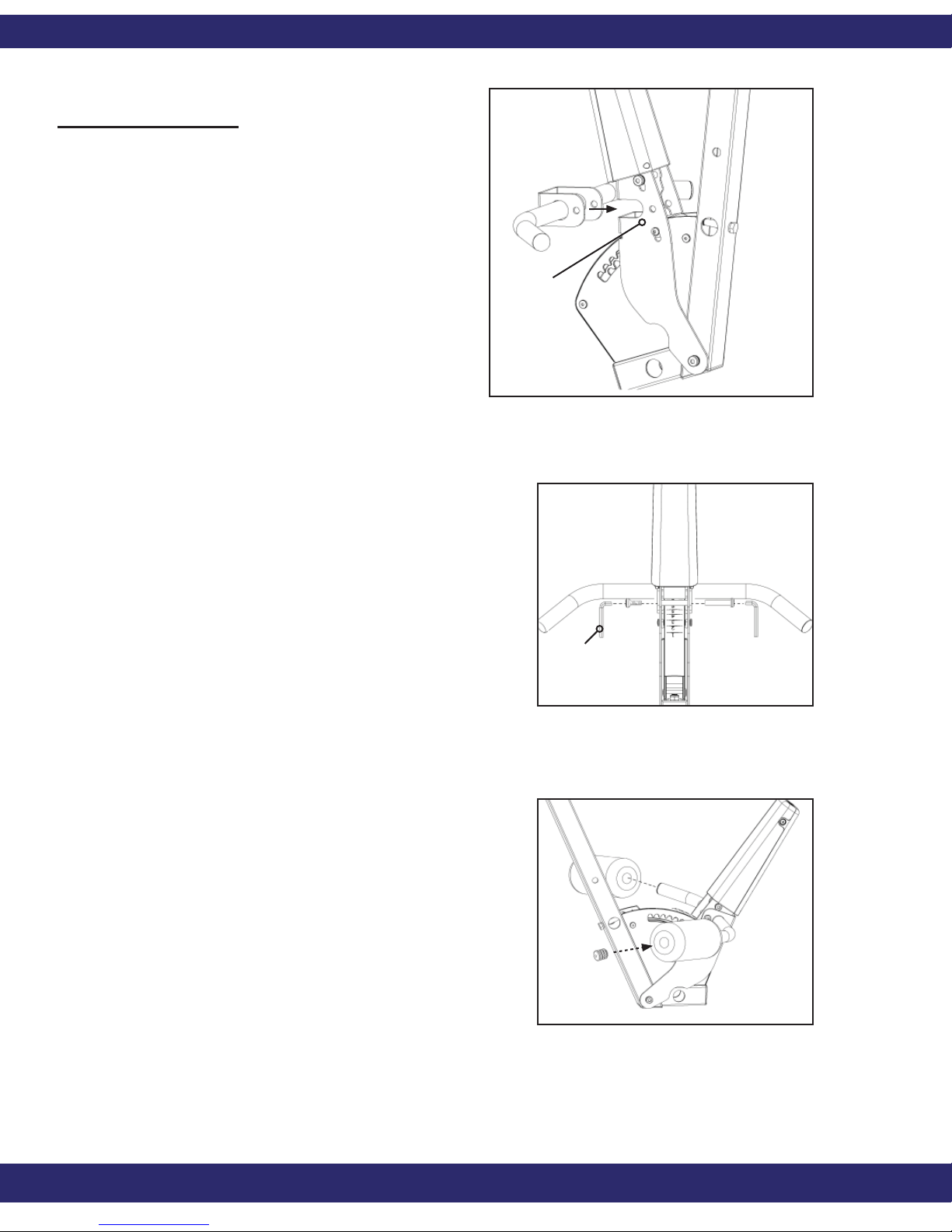
Install the Front Ankle Assembly
• Gather the Ankle Bar (F5-1047),
Black Plugs (F5-1056), Foam
Rollers (F5-1051), Bolt Sleeve
(IA-1110), and Sleeve Screw (IA-
1112).
• Stand in front of the Main Shaft
and slide the Ankle Bar over the
ratchet housing into the slot
(Figure 12).
• Align the bolt holes. Insert the
Bolt Sleeve through the holes
and secure with the Sleeve
Screw (Figure 13).Position one
Allen Wrench on the Sleeve
Screw and one on the Bolt
Sleeve to tighten.
Ratchet Housing
Figure 12
• Slide the Foam Rollers over each
side of the Ankle Bar (Figure 14).
• Insert the Black Plugs into both
ends of the Ankle Bar (Figure
14).
Allen Wrench
Figure 13
Figure 14
Teeter Hang Ups EP-950
9
Page 11
ASSEMBLY
Step Seven
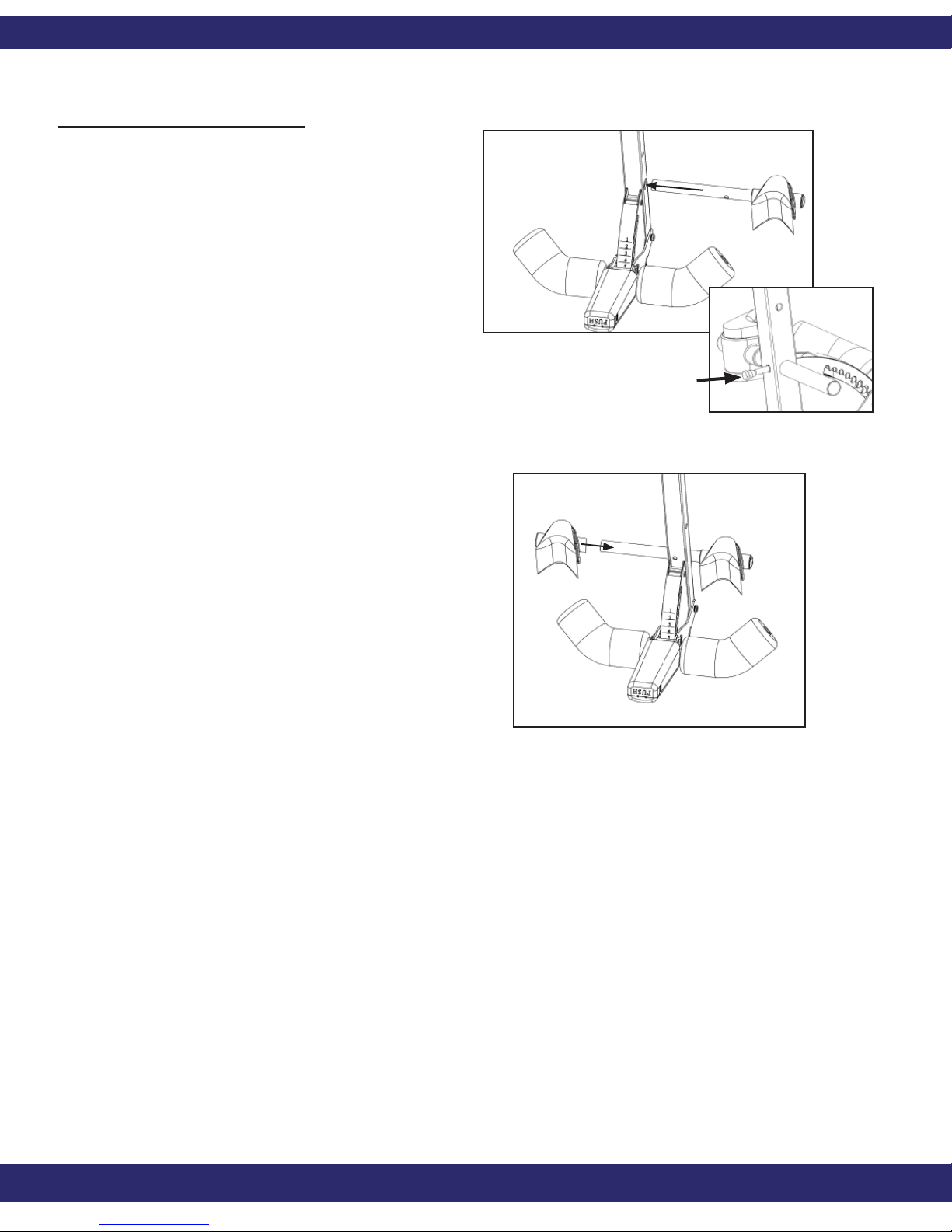
Install the Rear Bar Assembly
• With the rounded corners
of the rear foam Heel Cup
facing down, insert the Rear
Bar with one Heel Cup (IA-
1113) into the large hole
at the bottom of the Main
Shaft (Figure 15).
• Insert the Bolt (IA-1116) to
secure the Rear Bar to the
Main Shaft, and attach the
nut with the wrenches (F5-
1088) provided (Figure 16).
Figure 15
Figure 16
• Slip the other Heel Cup
(rounded corners down) onto
the Rear Bar and push the
Rubber Plug (F5-1056) into
the Rear Bar (Figure 17).
Figure 17
Teeter Hang Ups EP-950
10
Page 12
ASSEMBLY
Step Eight
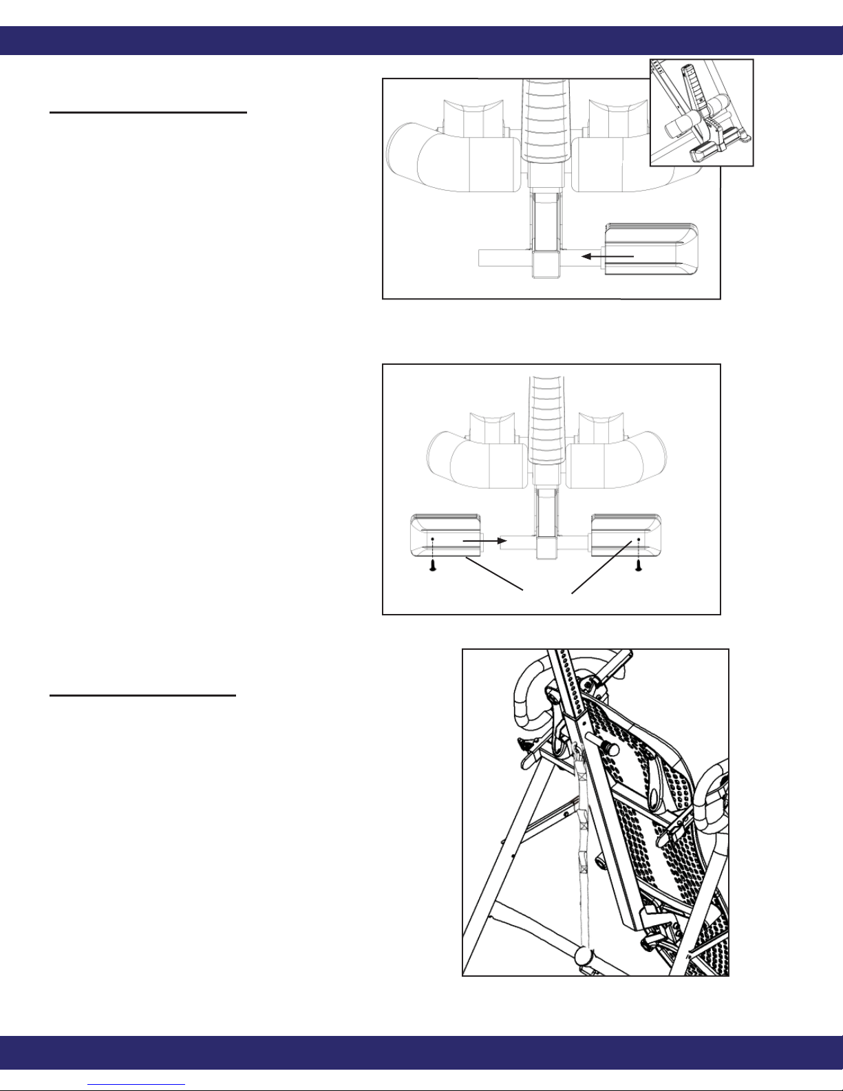
Install the Foot Platform
Assembly
• Slide the Foot Bar (IA-1119)
with one Foot Piece (IA-
1118) in the hole below the
ratchet (Figure 18).
• Slide the Foot Piece onto the
Bar (Figure 19).
• Insert the screws (IA-1123)
onto the Foot Platform and
tighten with the screw driver
(F5-1130) (Figure 19).
Figure 18
Note: The Foot Pieces are
designed with a High and
Low setting. Position in the
Low setting (screws facing
up) for ease of assembly.
Refer to Owner’s Manual for
a description of the settings.
Step Nine
Attach the EZ-Angle Tether Strap
(F5-1008) to Limit the Degree of
Rotation
• Hook the clip at the end of the tether
strap to the loop at the base of the
table bed (Figure 20) to limit your
Low Setting
Figure 19
degree of rotation.
• See the Owner’s Manual insert for
further instructions on adjusting the
strap.
Teeter Hang Ups EP-950
Figure 20
11
Page 13
ASSEMBLY
ADJUSTMENTS / MAINTENANCE / STORAGE
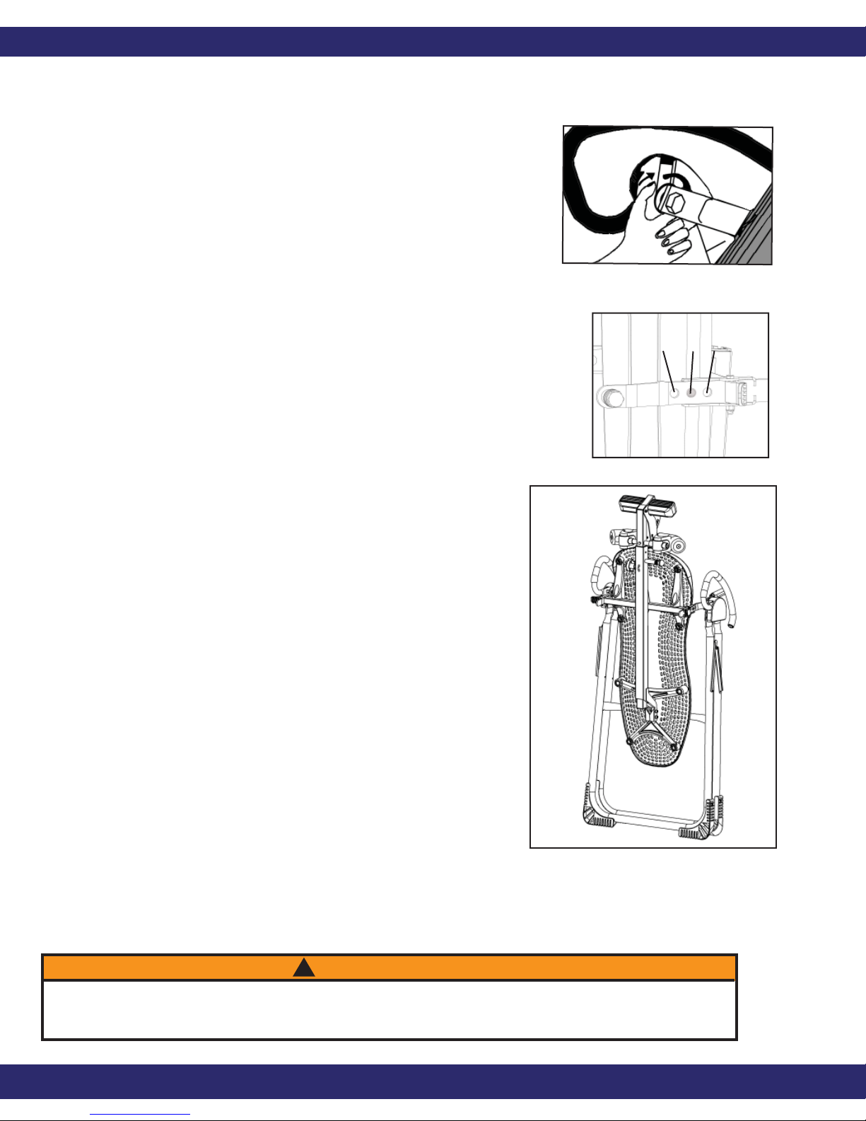
CHANGING THE ROLLER HINGE SETTING
Stand with your legs on either side of the Main
•
Shaft.
• Reach under each Roller Hinge with your index
fi ngers. Use your thumbs to release the locks over
the Roller Hinges (See Figure 21).
• Lift both sides of the table out of the A-frame at
the same time. You may rest the table on the
Crossbar of the A-frame.
• Unlock the Cam Locks for each Roller Hinge.
Change the Roller Hinges to the desired setting (A,
B or C) (Figure 22).
Figure 21
A B C
• Re-lock the Cam Locks. Replace the Roller Hinges
into the hinge plates of the A-frame.
MAINTENANCE
To clean the Table Bed, wipe down with a damp
•
cloth. Do not use abrasive cleaners.
STORING THE INVERSION TABLE
• Loosen the De-rattler knob.
• Pull the height-selector locking pin and slide the
Main Shaft in all the way to the fi nal hole setting.
Engage the pin in the storage setting.
• Rotate the table opposite from use until the table
has turned 180 degrees and rests against the
Crossbar on the A-frame.
• Pull up on the spreader arms to fold the
A-frame (Figure 23). WARNING: This operation
Figure 22
Figure 23
may pinch fi ngers if not done slowly and carefully.
WARNING
!
Read the Owner’s Manual thoroughly before using your Teeter Hang Ups
Inversion Table. Improper settings could result in serious injury or death!
Teeter Hang Ups EP-950
12
Page 14

Classifi ed as Medical Equipment, Part I in accordance with
UL 60601-1 and CAN/CSA C22.2; General Requirements for Safety in
accordance with Underwriters Laboratories, Inc.
Any Modifi cation to this device will void the UL Classifi cation.
If you have any problems assembling the equipment,
or questions about its use, please contact customer service at:
USA:
Teeter
9902 162nd St. Ct. E., Puyallup, WA 98375
Toll Free (Phone) 800-847-0143 (Fax) 800-847-0188
Local (Phone) 253-840-5252 (Fax) 253-840-5757
[email protected]
www.teeter-inversion.com
International:
Inversion International, Ltd.
PO Box: AP 59245
New Providence Island, Bahamas
(Phone) +1-242-362-1001 (Fax) +1-242-362-1002
[email protected]
www.InversionInternational.com
U.S. patents apply.
Teeter Hang Ups is a registered trademark of Teeter
Specifi cations subject to change without notice.
© COPYRIGHT 2008, Teeter
International Law Prohibits Any Copying, EP-2021; 0108-0
 Loading...