

Teeter Hang Ups DEX II Assembly And User's Manual

ASSEMBLY INSTRUCTIONS
USER MANUAL
DO NOT DISCARD - KEEP FOR FUTURE REFERENCE
ASSEMBLY INSTRUCTIONS
PRE-ASSEMBLY
Before you begin: These instructions will guide you in properly assembling the DEX IITM. Please review all the steps
before beginning assembly. Carefully adhere to the Assembly Instructions and User Manual to help ensure user security
and product integrity .
!
WARNING
1. It is your responsibility to familiarize yourself with the proper use of the equipment and the inherent risks of inversion, such as
falling on your head or neck, pinching, entrapment or equipment failure.
2. This product is NOT designed for persons over 6’6” (198 cm) or 300 lbs (136 kg). Structural failure could occur or head/neck
may impact floor during inversion. Serious injury or death could result.
3. DO NOT use the equipment without a licensed physician’s approval and a review of the medical contraindications, as noted in
the User Manual.
4. Failure to assemble and/or use the equipment as directed may void the manufacturer’s warranty on this product and could
result in injury or death.
5. DO NOT use the DEX II
documents, and inspected the equipment.
6. Choose a level surface for assembling and operating the DEX IITM.
7. Follow each step in sequence. Do not skip ahead.
8. Make sure that all fasteners are secure.
9. PRIOR TO USE, test and inspect the equipment. Make sure the Lap Pad rotates smoothly.
10. Replace defective components immediately and/or keep the equipment out of use until repair.
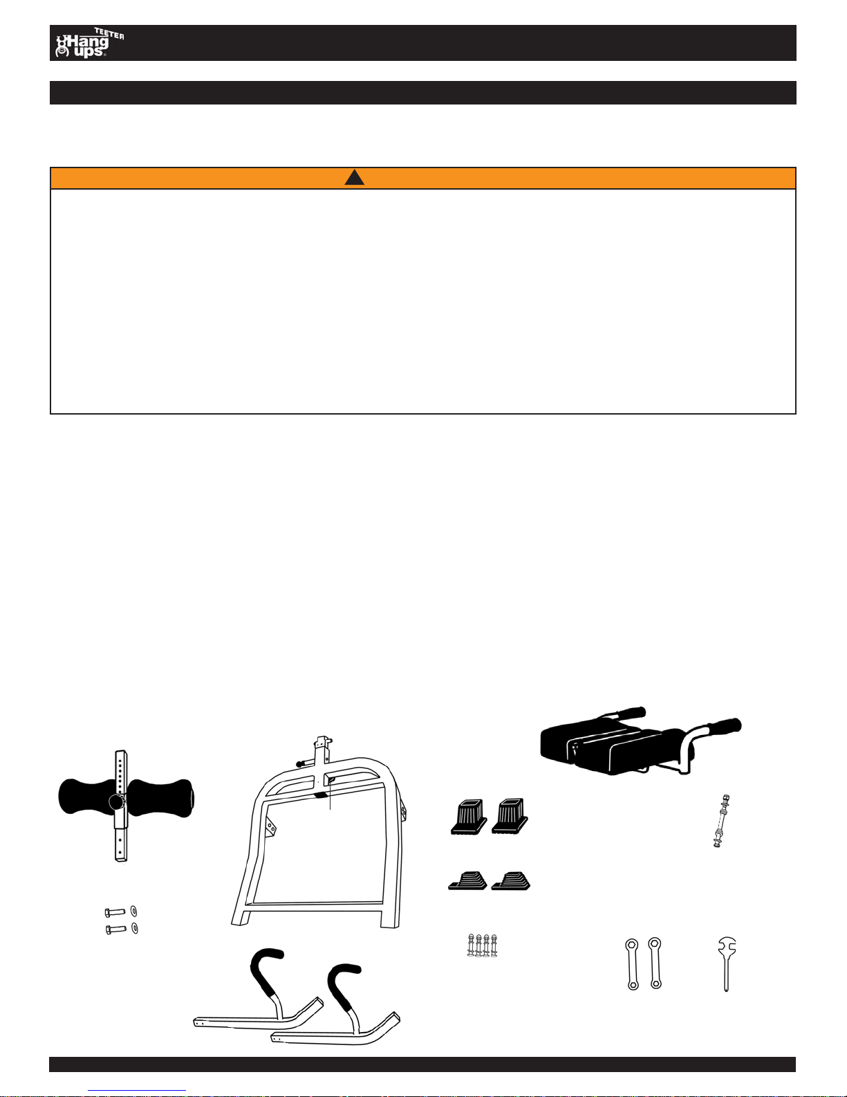
Carefully remove the individual parts from the carton. Y ou should have all of the items listed below . If any items are missing
or damaged, contact your retailer or customer service directly (See Pg. 4 of the User Manual).
TM
until you have thoroughly and carefully read the User Manual, reviewed all other accompanying
ITEMS FOR ASSEMBL Y ITEM #’s
Leg Support Assembly H1-2000
Leg Support Frame H1-2001
Leg Width Adjustment Knob H1-2016
Two (2) Rollers H1-2002
Two (2) Roller Caps H1-2003
Leg Support Shaft H1-2004
Two (2) Flat Washers (M8) H1-1414
Two (2) Hex Bolts (M8 x 25mm) H1-1415
Base Assembly H1-3008
Base Frame H1-2009
Height Adjustment Knob H1-2018
Two (2) Legs H1-2010
Two (2) Base Feet D1-1012
Two (2) Leg Feet D1-1013
Four (4) Threaded Bolts (3/8-16) H1-2011
Four (4) Bolt Caps (3/8-16) H1-2012
Four (4) Flat Washers (3/8) H1-2013
Four (4) Lock Washers (3/8) H1-1301
Lap Pad Assembly H1-2005
Lap Pad Frame H1-2006
Lap Pad D1-1005
Four (4) Screws H1-2007
Hex Bolt (3/8-16) H1-1412
Hex Nut (3/8-16) H1-1304
Two (2) Flat Washers (3/8) H1-1302
Two (2) Spacers H1-2017
Hardware
Two (2) Wrenches (13/14mm) H1-2014
Screwdriver H1-2015
H1-2005
H1-2000
H1-2009
H1-1414, H1-1415
(may come pre-assembled to
the Leg Support Shaft)
DEX IITM Assembly Instructions LD-2000 Pg. 1
H1-2018
H1-2010
D1-1012
H1-1412, H1-1304,
H1-1302, H1-2017
D1-1013
H1-2011, H1-2012,
H1-2013, H1-1301
some parts shown may not be in proportion to other parts
(may come pre-assembled to
the Lap Pad Assembly)
H1-2014
H1-2015
ASSEMBLY
ASSEMBLY INSTRUCTIONS
STEP ONE
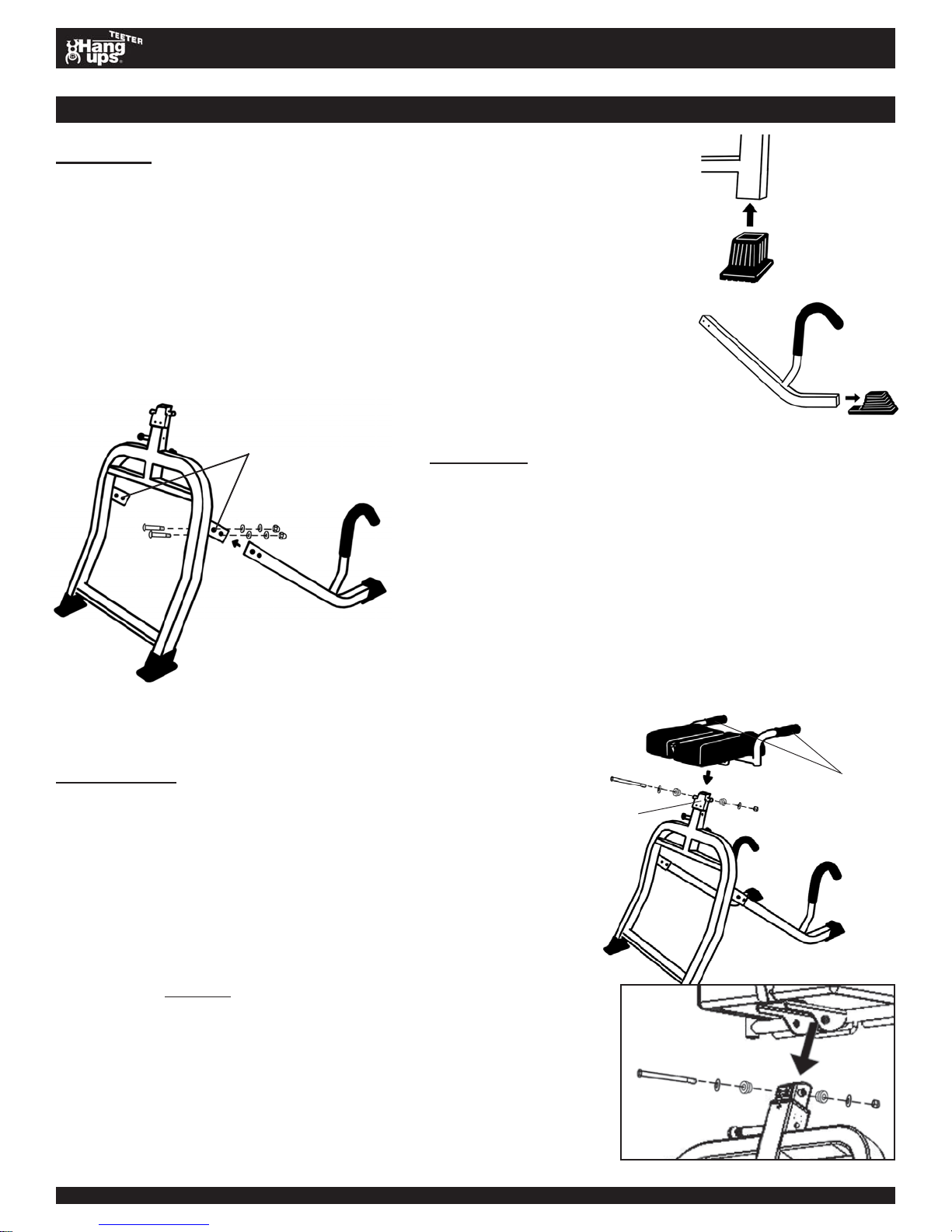
Assemble the Feet (D1-1012, D1-1013) onto the Base Frame (H1-2009)
and the Legs (H1-2010)
• Slide the Base Frame Feet (D1-1012) on to the Base Frame. (See
Figure 1A)
• Slide the Leg Feet onto the end of the Legs with the cane handle.
(See Figure 1B)
• Push firmly on all four feet to ensure they are fully mounted.
Figure 2
Leg Housings
STEP TWO
Attach the Legs (H1-2010) to the Base Frame (H1-2009)
• With the cane handles facing upward, insert the Legs into
the Leg Housings of the Base Frame until the two holes in
the Leg Housing align with the holes at the top of each
Leg. (See Figure 2)
• Insert a Threaded Bolt (H1-2011) from the inside of the
Leg Housing through the holes on each column. Finish
on the outside of the Base Frame using the Flat Washer
(H1-2013), Lock Washer (H1-1301) and Bolt Cap
(H1-2012) and tighten with Wrenches (H1-2014).
Figure 1A
Figure 1B
STEP THREE
Secure the Lap Pad Assembly (H1-2005) to the Chrome Shaft of
the Base Frame Assembly
• Remove the Hex Nut (H1-1304), Flat Washers (H1-1302) and
Spacers (H1-2017) from the Hex Bolt (H1-1412). Keep this
hardware nearby .
• With the Traction Handles facing the rear of the Base Frame
Assembly , place the Lap Pad Assembly over the Chrome Shaft in
the Base Frame and align the holes. (See Figure 3)
• Thread the Hex Bolt through a Flat Washer and S pacer . Make
sure the small end of the Spacer faces away from the head end
of the Hex Bolt.
• Insert the Hex Bolt with Flat Washer and S pacer through the
holes, securing the Lap Pad Assembly to the Chrome Shaft.
Thread the remaining Spacer with the small end facing the
Chrome Shaft and tighten with the Flat Washer and Hex Nut.
(See Figure 3A for close-up view)
• Make sure the fasteners are securely tightened and the Lap Pad
rotates smoothly .
DEX IITM Assembly Instructions LD-2000 Pg. 2
Figure 3
Chrome
Shaft
(Front)
(Rear)
Traction
Handles
Figure 3A
 Loading...